Abstract
This article describes the development of a high power density Direct Formate Fuel Cell (DFFC) fed with potassium formate (KCOOH). The membrane electrode assembly (MEA) contains no platinum metal. The cathode catalyst is FeCo/C combined with a commercial anion exchange membrane (AEM). To enhance the power output and energy efficiency we have employed a nanostructured Pd/C-CeO2 anode catalyst. The activity for the formate oxidation reaction (FOR) is enhanced when compared to a Pd/C catalyst with the same Pd loading. Fuel cell tests at 60 °C show a peak power density of almost 250 mW cm−2. The discharge energy (14 kJ), faradic efficiency (89%) and energy efficiency (46%) were determined for a single fuel charge (30 mL of 4 M KCOOH and 4 M KOH). Energy analysis demonstrates that removal of the expensive KOH electrolyte is essential for the future development of these devices. To compensate we apply for the first time a polymeric ionomer in the catalyst layer of the anode electrode. A homopolymer is synthesized by the radical polymerization of vinyl benzene chloride followed by amination with 1,4-diazabicyclo[2.2.2]octane (DABCO). The energy delivered, energy efficiency and fuel consumption efficiency of DFFCs fed with 4 M KCOOH are doubled with the use of the ionomer.
Keywords:
direct alcohol fuel cells; formate; alkaline membrane; palladium; ceria; ionomer; energy efficiency 1. Introduction
Direct Formate Fuel Cells (DFFCs) are attractive power sources because as a fuel formate salts have specific advantages compared to alcohols like methanol and ethanol [1]. Formate salts can be easily stored, transported, and handled in their solid state and can be combined with water to form a liquid fuel solution [2]. Worldwide production of its precursor formic acid is around 7.2 × 10⁵ t·y−1. Although industrial production involves fossil fuel derived precursors, formic acid can be obtained by renewable means such as the electrochemical reduction or catalytic hydrogenation of CO2 (the energy or hydrogen used in such processes must be derived from renewable energy sources) [3,4,5,6,7]. DFFCs operate under alkaline conditions, which is advantageous as both the formate oxidation reaction (FOR) and the oxygen reduction reaction (ORR) have high kinetics. Under basic conditions non-platinum catalysts can be used in the electrodes [8]. At high pH, the FOR does not pass through poisoning intermediates such as CO that can quickly passivate catalyst metal surfaces. A fuel cell running on formate and air at the cathode has a theoretical cell potential as high as 1.45 V (Equations (1)–(3)) which means DFFCs can produce high power densities:
Recent examples of platinum-free DFFCs equipped with a combination of anion exchange membranes (AEMs) and air or oxygen fed cathodes show the potential for high power devices with peak power densities in the range of 250–300 mW cm−2 (Tcell = 60 °C) [9,10,11,12,13,14]. We have recently reported a study of the energy efficiency of Pt-free DFFCs (Pd/C anode, FeCo/C cathode and AEM). The highest energy efficiency (42%) is obtained using high energy density fuel (4 M KCOOH and 4 M KOH) with a maximum operating temperature of 60 °C [15].
Another important aspect is that formate oxidation has fast kinetics, even when the OH− electrolyte (KOH or NaOH) is not present in the fuel solution, meaning that the fuel cell can also operate at intermediate pH values [9,16,17]. Haan et al. demonstrated that the FOR is not dependent on pH between 9 and 14, which permits the use of formate fuel without added hydroxide [18]. Alkaline direct alcohol fuel cells (DAFCs) that operate with an electrolyte consume at least one mole of base for every oxidized fuel molecule. A high pH (13–14) is also required to guarantee sufficient alcohol oxidation kinetics [19]. In general, these constraints make the fuel energy efficiencies of alkaline DAFCs very low (less than 7%) [20]. To this, we must also consider the energy cost of the base consumed in the fuel cell reaction which results in a negative energy yield for alkaline DAFCs [21]. Hence, removal of the costly electrolyte (e.g., KOH) is essential for a practical application of these devices as power sources. This is possible with formate as fuel. Haan and coworkers achieved 105 mW cm−2 peak power density with a 1 M aqueous HCOOK fuel solution [18]. Zhao et al. reached a peak power density of 130 mW cm−2 with 5 M HCOOK [14]. Instantaneous power density output (obtained from fuel cell polarization curves) is valuable in understanding the activity of the fuel cell system at its beginning of life. However, it must also be demonstrated that a DFFC operating with no added electrolyte can also produce sufficient discharge energy, fuel energy efficiency and fuel conversion efficiency on every single fuel loading. Without added electrolyte, the ionic conductivity of the membrane electrode assembly (MEA) is reduced significantly, leading to large ohmic losses. Improving the ionic conductivity within the catalyst layer is a key factor in overcoming the loss of ionic conductivity that is usually guaranteed by the liquid electrolyte. A number of research groups have developed anion exchange ionomers for inclusion in the catalyst layer of anion exchange MEAs. As far as we know these materials have been exclusively developed for H2/air or H2/O2 AEM-FCs [22,23].
Improved anodic catalyst materials are also required to increase the energy output and efficiency of DFFCs [24]. The activity and efficiency of Pd based nanoparticle anode catalysts for alkaline DAFCs have been shown to improve with the addition of certain metal oxides to the conductive carbon support [20,24,25]. The most successful demonstration of this phenomenon has been the addition of CeO2 to Vulcan XC-72 carbon [20]. This mixed support with deposited Pd nanoparticles showed enhanced activity for ethanol electrooxidation in DAFCs. The ceria contributes to the decrease of the onset potential of ethanol oxidation. It was proposed that CeO2 promotes the formation at low potentials of species adsorbed on Pd, (e.g., Pd(I)-OHads), that are involved in ethanol oxidation. The energy efficiency of the DAFC with Pd/C-CeO2 was shown to be double that of the same fuel cell with a Pd/C anode catalyst [20].
Here we report for the first time the use of a Pd/C-CeO2 anode catalyst for the FOR in DFFCs. We demonstrate that this catalyst has enhanced activity and fuel energy efficiency. In this paper, we also address the issue of removal of the liquid KOH electrolyte from the fuel solution. We include an energy analysis that shows that any added KOH electrolyte in the fuel solution results in a negative net energy delivery from the fuel cell. For the first time a polymeric ionomer is applied to improve the efficiency of DFFCs. Hence we report the synthesis and characterization of a polymeric ionomer based upon a styrenic 1,4-diazabicyclo[2.2.2]octane (DABCO) salt repeating unit. The application of this ionomer in the anode catalyst layer leads to a doubling of the DFFC energy efficiency with 4 M HCOOK as fuel (Tcell = 60 °C). The faradaic efficiency (fuel conversion) matches that of a cell fed with 4 M KOH electrolyte. The results of this study help to push the development of DFFCs closer to practical application.
2. Results and Discussion
2.1. Pd/C-CeO2 Catalyst FOR Activity
Two anode FOR catalysts are compared (Pd/C and Pd/C-CeO2) each with 10 wt % loading of Pd nanoparticles (NPs). Each was prepared as described in our previous publication [26]. In particular, Pd/C-CeO2 was prepared by the reduction and deposition of Pd onto a mixed conductive support (50 wt % carbon and 50 wt % CeO2 (C-CeO2)). A cyclic voltammetry (CV) investigation of Pd/C-CeO2 was undertaken in N2-saturated 2 M aqueous KOH solution at room temperature (Figure 1A). The CV curve shows features characteristic for both Pd and CeO2 centered transitions assigned by comparison to literature data as follows. On the forward anodic scan (0 to 1.4 V), there are three transitions. There is a broad peak centered at 0.4 V due to the oxidative desorption of hydrogen (A1). The peak at 0.6 V (A2) is ascribed to the formation of palladium hydroxides. At higher potentials (0.9−1.4 V), the formation of palladium oxides takes place. On the reverse cathodic scan (1.4 to 0 V), the peak at 0.7 V (C1) is assigned to the reduction of Pd oxides, whereas the broad cathodic transition at potentials between 0.4 to 0.2 V (C2) is attributed to hydrogen adsorption.
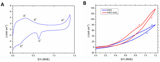
Figure 1.
(A) Typical CV of Pd/C-CeO2 in N2 saturated 2 M KOH (scan rate: 10 mV·s−1) and (B) Comparison of CVs obtained at room temperature of Pd/C-CeO2 and Pd/C in N2 saturated 2 M HCOOK + 0.5 M KOH (scan rate: 10 mV·s−1).
The electrochemical activity of Pd/C-CeO2 and Pd/C toward the oxidation of formate was investigated with an aqueous solution of 2 M HCOOK and added KOH electrolyte (0.5 M) (Figure 1B). The onset potential for both catalysts is around 0.2 V (RHE). The oxidizing current density increases linearly over the complete potential range (0 to 1.4 V). With the same Pd loading the C-CeO2 supported catalyst reaches 140 mA·cm−2 at 1.4 V compared to 80 for the Pd/C catalyst. On the forward scan Pd/C-CeO2 maintains a higher current density for all potentials above 0.4 V. The enhanced activity for the FOR with Pd/C-CeO2 with respect to Pd/C is due to the oxophilic nature of the CeO2 in the mixed C-CeO2 support and the three-phase (C, CeO2 and Pd) nanostructure. The CeO2 promotes the transfer of OH− to the Pd surface thus forming Pd-OHad species at low overpotentials that are involved in the FOR [20]. The surface nanostructure of this catalyst has been thoroughly characterized in our recent publications [25,26]. A combination of techniques including morphological studies i.e., HR-TEM, Z-contrast STEM, EDX mapping and XAS spectroscopy (XAFS, XANES, XRD) demonstrate that the unique nanostructure involves small Pd NPs (2–3 nm) that are deposited preferentially on the CeO2 portions of the support leaving the carbon part of the support free of Pd [26]. Such a structure enhances the Pd-CeO2 interactions and consequently the FOR activity. Indeed this effect results in the enhancement in activity and energy efficiency when applied in DFFCs as described in the next section.
2.2. DFFC Performance
Anode electrodes were prepared by coating a nickel foam support with a homogeneous mixture of PTFE and Pd/C-CeO2 (Pd loading of 2 mg·cm−2). The membrane electrode assembly (MEA) for cell testing was formed by pressing this anode electrode within the cell hardware together with an anion exchange membrane (A201, Tokuyama Corp., Tokyo, Japan) and a FeCo/C on carbon cloth cathode. The 4 M HCOOK fuel solution (30 mL) containing various concentrations of KOH (0, 1, 2 and 4 M) was recycled through the anode compartment while humidified O2 was flowed across the cathode. Cell potential scans and constant current experiments were carried out at a cell temperature of 60 °C. Cell voltage and power density curves are shown in Figure 2 and important fuel cell data is listed in Table 1.
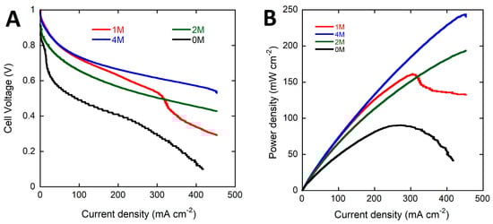
Figure 2.
Potential (A) and power density (B) (vs. current density) curves for the DFFC containing the Pd/C-CeO2 anode, FeCo/C cathode, A201 AEM and fueled with 4 M HCOOK and various concentrations of KOH electrolyte (0, 1, 2 and 4 M) (Tcell 60 °C and Vscan 10 mV·s−1).

Table 1.
Fuel cell data for DFFCs with single fuel load (MEA; Pd/C-CeO2 anode, FeCo/C cathode, AEM A-201 (Tcell 60 °C)).
The performance of the DFFC is highly dependent upon the KOH electrolyte concentration. As can be seen in Table 1 the peak power density decreases from 243 to 206 and to 159 (mW·cm−2) as the KOH concentration drops from 4 to 2 and 1 M. Mass transport limited cell performance is observed in the 4/1 fuel solution at higher current densities due to excessive consumption of KOH near the electrode surface. The voltage curve obtained with no added KOH shows a significant drop in the cell potential at low current densities caused by poor FOR activity of the anode catalyst at the mildly alkaline conditions of the 4 M HCOOK solution. A peak power density of 89 mW·cm−2 is obtained with no KOH, 40% of that obtained with an equivalent molar amount of KOH in the electrolyte (4 M).
The energy delivery of the DFFC with single fuel batches (30 cc) was studied by performing constant current density experiments (50 mA·cm−2) while monitoring the cell potential. Each experiment was stopped when the cell potential reached 0 V. Three consecutive experiments were carried out for each fuel composition replacing the spent solution each time with fresh fuel. The values of discharge energy (kJ), faradic efficiency (%) and energy efficiency (%) were calculated as shown in the supporting information (SI). The data shown in Table 1 are the average of three experiments. Typical cell voltage vs. time curves are shown in Figure 3. The best power delivery is obtained with the 4 M HCOOK, 4 M KOH fuel. The values of discharge energy (14 kJ), faradic efficiency (89%) and energy efficiency EE (46%) calculated as the average of three consecutive 30 cc fuel batches are better than the values obtained under identical conditions with a Pd/C catalyst at the anode (12.5 kJ, 88% and 42% respectively) in our recent study [15]. Such high values are obtained with the aid of the KOH electrolyte present in the fuel solution. The DFFC running with 4 M HCOOK (no KOH) performs poorly (2 kJ, 51% and 7% respectively). When KOH is present in the fuel solution one mole is consumed with every oxidized formate molecule (Equation (3)). We can estimate the additional cost in energy terms of the base consumed in the reaction (6.2 kJ/g is the net energy cost of electrolytic KOH production) [27] and calculate whether the addition of KOH to the fuel solution is energetically convenient (Table 2). The data shows clearly that the use of added KOH electrolyte results in a net negative energy balance. The energy obtained from the cell is less than that used in the production of the OH− consumed in the fuel cell reaction. Only a formate fuel solution without KOH results in a positive energy gain. When no base is present in the fuel solution the product of oxidation CO2 is released as gas (Equation (4)) [9,10,18,28].
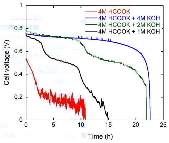
Figure 3.
Galvanostatic curves at 50 mA·cm−2 at 60 °C for the DFFC containing the Pd/C-CeO2 anode, FeCo/C cathode, and fueled with 4 M HCOOK and various concentrations of KOH electrolyte.
Table 2.
Energy analysis for DFFCs (MEA; Pd/C-CeO2 anode, FeCo/C cathode, AEM A-201 (Tcell 60 °C). * MEA with ionomer.
2.3. Ionomer Synthesis and Performance
Without the presence of KOH electrolyte, the energy delivered by the DFFC from the fuel supplied is low (Table 1). Around 50% of the fuel is consumed and 7% of the chemical energy in the fuel is converted into electrical energy. The strategy we have employed to improve the performance of DFFCs operating without added electrolyte is to improve the ionic conductivity within the catalyst layer by the addition of an anion exchange ionomer to the PTFE bound electrode. For effective dispersion, such a material requires that the positively charged polymer is soluble in organic media to allow mixing within the catalyst ink. This must be also combined with other optimized properties of hydrophobicity and high functional group concentration (IEC) [29]. The material chosen is a homopolymer obtained by a two-step synthesis based upon (1) free-radical polymerization of 4-vinyl benzene chloride (VBC) followed by (2) amination with DABCO [30]. The polymer was obtained as follows. After purification of the monomer by standard techniques, radical polymerization was used to form poly(vinylbenzyl chloride) (pVBC). This precursor material was characterized by 1H NMR spectroscopy, GPC, FTIR, DSC and TGA (See Supplementary Materials).
The homopolymer pVBC was treated with a large excess of DABCO. The complete transformation of the CH2Cl groups to quaternary ammonium salts is shown by the FTIR spectra as bands representative of the CH2Cl group (1265 and 700 cm−1) are replaced by those representative of quaternary ammonium groups (1320–1465 and 1057 cm−1) (Figure 4) [31]. A large molar excess of DABCO was used to avoid the possibility of cross-linking between pVBC chains through the quaternization of both DABCO tertiary amine groups. Nevertheless, if a certain crosslink among PVBC macromolecules occurs, it would be beneficial for the structural stabilization of the MEA. It has also been demonstrated that moderate amounts of crosslinking promoted by DABCO are able to decrease the water uptake, while not reducing ionic conductivity [30,32]. Fundamental properties; water uptake, ion-exchange capacity and ionic conductivity were not measured due to the poor mechanical properties after film casting. A very high water uptake (confirming that negligible crosslinking occurred) made the polymer film unstable in water. Cast films quickly broke up on contact with water forming a suspension. Nevertheless, this pVBC-DABCO polymer was effectively used to prepare a stable MEA.
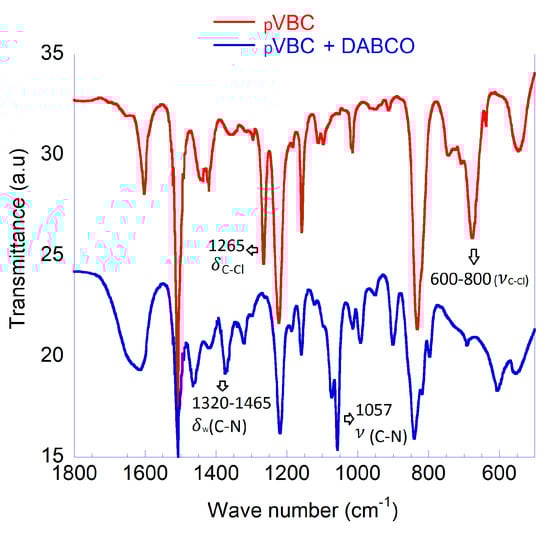
Figure 4.
Characterization of pVBC and pVBC-DABCO; FTIR spectroscopy.
2.4. Ionomer Performance in DFFCs
The pVBC-DABCO polymer was dissolved in methanol to form a 4 wt % ionomer solution. This solution was used to add the required amount of polymer to the anode catalyst ink before application to the nickel foam support. The content of the dry anode electrode was as follows; 20, 2 and 1 (mg·cm−2) for the Pd/C-CeO2, PTFE and pVBC-DABCO respectively. This anode electrode containing the pVBC-DABCO ionomer was tested in DFFCs at 60 °C fed with 4 M HCOOK. The performance in power curves and galvanostatic tests is shown in Figure 5. The presence of the ionomer in the anode catalyst layer results in a net improvement in both the peak power density as well as the energy delivered from a single fuel load during batch testing. The values are listed in Table 1. Most notably, the faradaic efficiency or fuel consumption is doubled with respect to the MEA without ionomer and more importantly is the same as a fuel solution with 4 M KOH. Hence, added KOH is not necessary to reach 90% fuel consumption. The cell operates with an energy efficiency of 12% almost twice that of the MEA with no ionomer. This to the best of our knowledge is the best EE yet reported for DFFCs operating without added electrolyte. By comparison, the best efficiency reported for a direct ethanol fuel cell operating with added KOH (2 M ethanol and 2 M KOH) is around 7% [20].
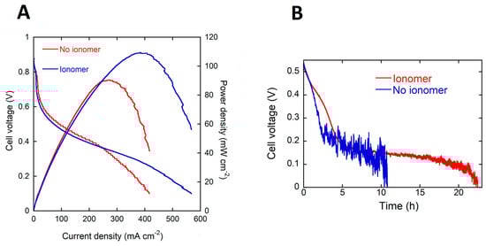
Figure 5.
(A) Potential and power density (vs. current density) curves for the DFFC containing the Pd/C-CeO2 anode, FeCo/C cathode, A201 AEM and fueled with 4 M HCOOK (B) energy delivery from 4 M HCOOK fuel with and without ionomer in the catalyst layer.
To make DFFC devices running on fuel without KOH practical will require an improvement in the energy produced from a single fuel batch. In practice this means increasing the cell working potential above 600 mV while running. To do this will require increasing the activity of the anode and cathode catalysts working at near neutral pH. Improvement in the ionomer performance and optimization of the electrode structure will also improve the performance.
3. Conclusions
In summary, we have improved the energy delivery of alkaline DAFCs fed with formate as fuel by developing two of the critical materials used in the formation of the MEA. Firstly, the anode catalyst, which is fundamental to performance as the kinetics of anodic oxidation of liquid-fuels such as alcohols are notoriously sluggish. Palladium NPs deposited onto a mixed conductive support of carbon and CeO2 exhibit enhanced kinetics for the FOR due to the activated oxygen transfer from ceria to Pd that favors the formation of active Pd-OHads species at low overpotentials. When fed with 4 M formate and 4 M KOH, the peak power density (253 mW·cm−2), discharge energy (14 kJ), faradic efficiency (89%) and energy efficiency (46%) are the best yet reported for DFFCs. Importantly, we have removed the expensive KOH electrolyte from the fuel and shown that the performance can be enhanced by the addition of a polymeric ionomer to the anode catalyst layer. The fuel conversion efficiency with this new MEA is equivalent to a DFFC with KOH in the fuel solution. The energy discharged and the energy efficiency doubled compared to the MEA without the added ionomer. The energy efficiency of the cell with ionomer and no KOH was 12%. This level is still too low for practical use as a power source. The challenge for researchers is to optimize the components of the MEA (catalysts and ionomers/membranes) in order to match the fuel efficiency of DFFCs fed with KOH in the fuel. This is the object of current research in our laboratories.
4. Materials and Methods
4.1. Chemicals
Carbon black (Vulcan XC-72 pellets) was obtained from Cabot Corp. (Boston, MA, USA). The FeCo/C (3 wt % FeCo) cathode electrocatalyst was synthesized by a method reported elsewhere [33,34]. All metal salts and reagents were purchased from Merck (Darmstadt, Germany) and used as received. All the solutions were freshly prepared with doubly distilled deionized water. The anion exchange solid polymer membrane used in the DAFCs was A-201 obtained from Tokuyama Corporation which has the following characteristics; thickness (in dry form) 28 μm, ion exchange capacity 1.8 mmol g−1, water uptake ca. 30% and ion conductivity 12 ms·cm−1 (HCO3− form).
4.2. Synthesis of Pd/C (10 wt %)
Vulcan XC-72 (6.0 g) was suspended in 250 mL of ethylene glycol and sonicated for 20 min in a 500 mL three-neck round-bottomed flask. Then a solution of 1.0 g of PdCl2 in a mixture of H2O (50 mL), ethylene glycol (50 mL) and 6 mL HCl (37%) was added dropwise under stirring in a N2 stream. After adequate stirring, an alkaline solution of NaOH (5 g) in H2O (10 mL) and ethylene glycol (35 mL) was introduced in the reactor which then was heated at 125 °C for 3 h again under a N2 atmosphere. Then the mixture was cooled to room temperature. The solid product was filtered off and washed with H2O to neutral pH. The final product was dried in vacuum oven at 40 °C. (Yield: 6.53 g).
4.3. Synthesis of C-CeO2 Support (50:50)
Vulcan XC-72 (4 g) was added to a solution of Ce(NO3)3·6H2O (10.1 g) in H2O (250 mL). The mixture was kept under stirring for 60 min and sonicated for 30 min. After adjusting the pH to 12 with KOH, the resulting suspension was stirred for 2 h. The product was separated by filtration and washed with H2O until neutral pH was obtained. The product was dried at 65 °C, and then heated under air in a tube furnace at 250 °C for 2 h. Cooling to room temperature was undertaken under a flow of N2. The yield of C-CeO2 was 7.15 g.
4.4. Synthesis of Pd/C-CeO2 (10 wt % Pd)
C-CeO2 (4 g) was suspended in water (500 mL), stirred vigorously for 30 min and sonicated for 20 min. To this mixture, a solution of K2PdCl4 (1.38 g) in water (60 mL) was slowly added (1 mL·min−1) under vigorous stirring, followed by addition of an aqueous solution of 2.5 M KOH (8.4 mL). Ethanol (50 mL) was added and the resulting mixture was heated at 80 °C for 60 min. The desired product Pd/C-CeO2 was collected by filtration, washed several times with distilled water to neutrality and finally dried at 65 °C until constant weigh was reached. The yield of Pd/C-CeO2 was 4.45 g.
4.5. Electrochemical and Physical Characterization
Cyclic Voltammetry (CV) measurements were performed with a Princeton 2273A potentiostat/galvanostat (Princeton Applied Research, Oak Ridge, TN, USA), using a three-electrode arrangement with an Ag/AgCl reference electrode and a platinum foil (25mm × 25mm × 0.1mm) as counter electrode. No IR drop compensation was applied to any of the performed experiments. The potential scale of the CV curves was then converted to the reversible hydrogen electrode (RHE) scale.
Infrared spectra were performed with a Spectrum One Fourier transform spectrometer (Perkin–Elmer™, Shelton, CT, USA), on neat and functionalized LDPE films. Attenuated Total Reflectance Fourier Transform Infrared (ATR/FTIR) spectra were recorded on polymer films with the help of a Perkin–Elmer Spectrum One spectrometer fitted with a Universal ATR (UATR, DiComp™ crystal, Perkin–Elmer™, Shelton, CT, USA) accessory.
Differential scanning calorimetry (DSC) analyses were performed under nitrogen flux (80 mL/min) with a Perkin-Elmer DSC4000 (Shelton, CT, USA) equipped with intracooler and interfaced with Pyris software (version 9.0.2). The range of temperatures investigated was 40–180 °C. Thermal scans were carried out on 5–10 mg samples in aluminum pans under nitrogen atmosphere. The instrument was calibrated by the standards In (Tm = 156.6 °C, ΔHm = 28.5 J/g) and Pb (Tm = 327.5 °C, ΔHm = 23.03 J/g).
Thermogravimetric analysis (TGA) was carried out by an Exstar 7200 system (Hitachi, Tokyo, Japan). Samples were heated from 25 °C to 700 °C at 10 °C/min under a 200 mL/min of nitrogen flow.
Gel Permeation Chromatography (GPC) was used to determine molecular weights and molecular weight dispersion (Mw/Mn) of polymer samples with respect to polystyrene standards. GPC measurements were performed in CHCl3 as solvent on a four-channel pump PU-2089 Plus chromatograph (Jasco, Easton, MD, USA) equipped with a Jasco RI 2031 Plus refractometer and a multichannel Jasco UV-2077 Plus UV-Vis detector set at 252 and 360 nm. The flow rate was 1 mL min−1 at a temperature of 30 °C held through a Jasco CO 2063 Plus Column Thermostat. A series composed by two PLgel™ MIXED D columns and a PLgel™ precolumn (Polymer Laboratories, Church Stretton, UK) packed with polystyrene-divinylbenzene was used to perform the analysis (linearity range 100 Da–400 kDa).
4.6. Polymer Synthesis
4-Vinylbenzyl chloride (VBC) (4-(chloromethyl) styrene, Aldrich, 90%) was purified by washing it twice with a 25% (v/v) aqueous sodium hydroxide solution, and then thoroughly with distilled water until neutral pH. Finally, the monomer was distilled at reduced pressure and stored under nitrogen over molecular sieves at −20 °C. α,α′-Azobisisobutyronitrile (AIBN, Carlo Erba, Milano, Italy) was purified by recrystallization from acetone. 1,4-Diazabicyclo[2.2.2]octane (DABCO) (Sigma-Aldrich, ≥99%) was used as received.
4.6.1. Preparation of pVBC
Poly(vinylbenzyl chloride) (pVBC) was prepared by radical bulk polymerization of VBC (2.5 mL) in the presence of 1% by mol of AIBN (29 mg). The solution was stirred at 70 °C for two hours under nitrogen atmosphere. The crude product was then purified by a double dissolution in chloroform and precipitation in methanol and recovered after drying at reduced pressure. The yield of polymer was 52%.
4.6.2. Preparation of pVBC-DABCO
The purified pVBC (0.5 g) was dissolved in 200 mL of methanol in the presence of a large molar excess of DABCO (5 g, 45 mmol) and the solution was stirred at 60 °C for 48 h during which the solution became turbid. The reaction mixture was concentrated by evaporating the methanol to obtain a white solid. The unreacted DABCO present was removed by washing thoroughly with THF. The solid thus obtained was dried in a desiccator for 48 h until constant weight. 0.8 g of a white solid was recovered.
4.7. Fuel Cell MEAs
The anode electrodes were prepared as follows, a dense catalyst paste was prepared by mixing the catalyst Pd/C-CeO2 (100 mg) with an aqueous dispersion of PTFE (100 mg of a 10 wt % PTFE dispersion in H2O) and pVBC-DABCO solution (125 mg of a 4 wt % solution in methanol), distilled water (200 mg) and 1-propanol. The catalyst paste was applied uniformly to a porous nickel foam support (110 PPI HZTYKJ), dimensions 5 cm2, from Heze Tianyu Technology Development Co., Ltd. (Shandong, China). The thus prepared anode had a dry catalyst loading of 20 mg cm−2 and a Pd loading of 2 mg·cm−2.
The cathode electrode for all fuel cell tests was prepared using a FeCo/C cathode catalyst. A catalyst ink was prepared by mixing the required amount of FeCo/C with an aqueous dispersion of PTFE (100 mg of a 10 wt % PTFE dispersion in H2O) (final loading of 10 wt % PTFE), distilled water and ethanol. A stable ink was obtained after thorough mixing and sonication. The ink was applied to a carbon cloth substrate coated with a hydrophobic microporous carbon layer (MPL) (W1S1005, CeTech Co. Ltd., Taichung, Taiwan) by brush coating until the desired catalyst loading of ca. 2 mg·cm−2 was obtained. Both the cathode and anode electrodes after drying were further wet proofed by heating to 340 °C for 20 min under a flow of pure N2.
4.8. Fuel Cell Tests
The active fuel cell system suitable for corrosive liquid fuel solutions was obtained from Scribner-Associates (Southern Pines, NC, USA) with a 25 cm2 fuel cell fixture and an effective electrode area of 5 cm2. The MEAs were fabricated by mechanically pressing anode, Tokuyama A201 anion exchange membrane and cathode (FeCo/C on carbon cloth) within the fuel cell hardware. The fuel solution was delivered to the anode at 1 mL·min−1 by a micro-pump, while the oxygen flow at the cathode was regulated at 0.1 L·min−1. The temperature of the cell and of the oxygen gas temperature and humidification were regulated using a Scribner 850e fuel cell test station. The entry temperature of the fuel and cell temperature were set at 60 °C. The fuel cell performance was monitored with an ARBIN BT-2000 5A 4 channels instrument (Arbin Instruments, College Station, TX, USA). Fuel cell polarization curves were obtained at 10 mV·s−1 scan rate from OCV to 0.1 V. Galvanostatic experiments were undertaken at a constant current density of 50 mA·cm−2. The cell potential was monitored and the tests were stopped when the potential reached 0 V.
Supplementary Materials
The following are available online at http://www.mdpi.com/1996-1073/11/2/369/s1, Section S1: Description of energy calculations, Figure S1: pVBC-DABCO polymeric structure, Figure S2: 1H NMR spectrum of pVBC, Figure S3: TGA analysis, Figure S4: DSC analysis, Table S1: Polymer properties.
Acknowledgments
Ente Cassa di Risparmio di Firenze (project EnergyLab). We also thank Roberto Spiniello for performing the TGA/DSC analysis.
Author Contributions
H.A.M. and F.V. conceived and designed the experiments and wrote the paper; J.R. synthesized catalysts and preformed the fuel cell tests; M.B. and M.V.P. performed the electrochemical testing; A.M. performed the NMR and FTIR analysis; A.P. designed and synthesized the polymer; E.P. analyzed the TGA and DSC data. C.B designed and constructed the electrochemical test cell.
Conflicts of Interest
The authors declare no conflict of interest.
References
- An, L.; Chen, R. Direct formate fuel cells: A review. J. Power Sources 2016, 320, 127–139. [Google Scholar] [CrossRef]
- Vo, T.; Purohit, K.; Nguyen, C.; Biggs, B.; Mayoral, S.; Haan, J.L. Formate: An Energy Storage and Transport Bridge between Carbon Dioxide and a Formate Fuel Cell in a Single Device. ChemSusChem 2015, 8, 3853–3858. [Google Scholar] [CrossRef] [PubMed]
- Jones, J.P.; Prakash, G.K.S.; Olah, G.A. Electrochemical CO2 Reduction: Recent Advances and Current Trends. Isr. J. Chem. 2014, 54, 1451–1466. [Google Scholar] [CrossRef]
- Spinner, N.S.; Vega, J.A.; Mustain, W.E. Recent progress in the electrochemical conversion and utilization of CO2. Catal. Sci. Technol. 2012, 2, 19–28. [Google Scholar] [CrossRef]
- Qiao, J.L.; Liu, Y.Y.; Hong, F.; Zhang, J.J. A review of catalysts for the electroreduction of carbon dioxide to produce low-carbon fuels. Chem. Soc. Rev. 2014, 43, 631–675. [Google Scholar] [CrossRef] [PubMed]
- Gunasekar, G.H.; Park, K.; Jung, K.D.; Yoon, S. Recent developments in the catalytic hydrogenation of CO2 to formic acid/formate using heterogeneous catalysts. Inorg. Chem. Front. 2016, 3, 882–895. [Google Scholar] [CrossRef]
- Xu, Z.; McNamara, N.D.; Neumann, G.T.; Schneider, W.F.; Hicks, J.C. Catalytic Hydrogenation of CO2 to Formic Acid with Silica-Tethered Iridium Catalysts. ChemCatChem 2013, 5, 1769–1771. [Google Scholar] [CrossRef]
- Yang, Z.Y.; Wang, Y.E.; Dong, T.; Yuan, X.F.; Lv, L.L.; Wei, X.B.; Wang, J. Formate: A Possible Replacement for Formic Acid in Fuel Cells. Aust. J. Chem. 2017, 70, 757–763. [Google Scholar] [CrossRef]
- Li, Y.S.; Sun, X.D.; Feng, Y. Hydroxide Self-Feeding High-Temperature Alkaline Direct Formate Fuel Cells. ChemSusChem 2017, 10, 2135–2139. [Google Scholar] [CrossRef] [PubMed]
- Li, Y.S.; Feng, Y.; Sun, X.D.; He, Y.L. A Sodium-Ion-Conducting Direct Formate Fuel Cell: Generating Electricity and Producing Base. Angew. Chem. Int. Ed. 2017, 56, 5734–5737. [Google Scholar] [CrossRef] [PubMed]
- Da Silva, S.G.; Silva, J.C.M.; Buzzo, G.S.; Neto, A.O.; Assumpcao, M.H.M.T. Use of PtAu/C electrocatalysts toward formate oxidation: Electrochemical and fuel cell considerations. Mater. Renew. Sustain. 2016, 5, 15. [Google Scholar] [CrossRef]
- Nguyen, T.Q.; Minami, D.; Hua, C.; Miller, A.; Tran, K.; Haan, J.L. Ambient Temperature Operation of a Platinum-Free Direct Formate Fuel Cell. J. Fuel Cell Sci. Technol. 2015, 12, 014501. [Google Scholar] [CrossRef]
- Da Silva, S.G.; Silva, J.C.M.; Buzzo, G.S.; Spinace, E.V.; Neto, A.O.; Assumpcao, M.H.M.T. PdAu/C Electrocatalysts as Anodes for Direct Formate Fuel Cell. Electrocatalysis 2015, 6, 442–446. [Google Scholar] [CrossRef]
- Zeng, L.; Tang, Z.K.; Zhao, T.S. A high-performance alkaline exchange membrane direct formate fuel cell. Appl. Energy 2014, 115, 405–410. [Google Scholar] [CrossRef]
- Wang, L.Q.; Bellini, M.; Filippi, J.; Folliero, M.; Lavacchi, A.; Innocenti, M.; Marchionni, A.; Miller, H.A.; Vizza, F. Energy efficiency of platinum-free alkaline direct formate fuel cells. Appl. Energy 2016, 175, 479–487. [Google Scholar] [CrossRef]
- Yan, B.; Concannon, N.M.; Milshtein, J.D.; Brushett, F.R.; Surendranath, Y. A Membrane-Free Neutral pH Formate Fuel Cell Enabled by a Selective Nickel Sulfide Oxygen Reduction Catalyst. Angew. Chem. Int. Ed. 2017, 56, 7496–7499. [Google Scholar] [CrossRef] [PubMed]
- Li, Y.S. A liquid-electrolyte-free anion-exchange membrane direct formate-peroxide fuel cell. Int. J. Hydrog. Energy 2016, 41, 3600–3604. [Google Scholar] [CrossRef]
- Nguyen, T.Q.; Bartrom, A.M.; Tran, K.; Haan, J.L. Operation of the Alkaline Direct Formate Fuel Cell in the Absence of Added Hydroxide. Fuel Cells 2013, 13, 922–926. [Google Scholar] [CrossRef]
- Wang, L.Q.; Lavacchi, A.; Bevilacqua, M.; Bellini, M.; Fornasiero, P.; Filippi, J.; Innocenti, M.; Marchionni, A.; Miller, H.A.; Vizza, F. Energy Efficiency of Alkaline Direct Ethanol Fuel Cells Employing Nanostructured Palladium Electrocatalysts. ChemCatChem 2015, 7, 2214–2221. [Google Scholar] [CrossRef]
- Bambagioni, V.; Bianchini, C.; Chen, Y.X.; Filippi, J.; Fornasiero, P.; Innocenti, M.; Lavacchi, A.; Marchionni, A.; Oberhauser, W.; Vizza, F. Energy Efficiency Enhancement of Ethanol Electrooxidation on Pd-CeO2/C in Passive and Active Polymer Electrolyte-Membrane Fuel Cells. ChemSusChem 2012, 5, 1266–1273. [Google Scholar] [CrossRef] [PubMed]
- Chen, Y.X.; Lavacchi, A.; Miller, H.A.; Bevilacqua, M.; Filippi, J.; Innocenti, M.; Marchionni, A.; Oberhauser, W.; Wang, L.; Vizza, F. Nanotechnology makes biomass electrolysis more energy efficient than water electrolysis. Nat. Commun. 2014, 5, 4036. [Google Scholar] [CrossRef] [PubMed]
- Varcoe, J.R.; Atanassov, P.; Dekel, D.R.; Herring, A.M.; Hickner, M.A.; Kohl, P.A.; Kucernak, A.R.; Mustain, W.E.; Nijmeijer, K.; Scott, K.; et al. Anion-exchange membranes in electrochemical energy systems. Energy Environ. Sci. 2014, 7, 3135–3191. [Google Scholar] [CrossRef]
- Piana, M.; Boccia, M.; Filpi, A.; Flammia, E.; Miller, H.A.; Orsini, M.; Salusti, F.; Santiccioli, S.; Ciardelli, F.; Pucci, A. H-2/air alkaline membrane fuel cell performance and durability, using novel ionomer and non-platinum group metal cathode catalyst. J. Power Sources 2010, 195, 5875–5881. [Google Scholar] [CrossRef]
- MIller, H.A.; Vizza, F.; Lavacchi, A. Direct Alcohol Fuel Cells: Nanostructured Materials for the Electrooxidation of Alcohols in Alkaline Media. In Nanomaterials for Fuel Cell Catalysts; Ozoemena, K.I., Chen, S., Eds.; Springer: Basel, Switzerland, 2016; pp. 447–516. [Google Scholar]
- Miller, H.A.; Vizza, F.; Marelli, M.; Zadick, A.; Dubau, L.; Chatenet, M.; Geiger, S.; Cherevko, S.; Doan, H.; Pavlicek, R.K.; et al. Highly active nanostructured palladium-ceria electrocatalysts for the hydrogen oxidation reaction in alkaline medium. Nano Energy 2017, 33, 293–305. [Google Scholar] [CrossRef]
- Miller, H.A.; Lavacchi, A.; Vizza, F.; Marelli, M.; Di Benedetto, F.; Acapito, F.D.I.; Paska, Y.; Page, M.; Dekel, D.R. A Pd/C-CeO2 Anode Catalyst for High-Performance Platinum-Free Anion Exchange Membrane Fuel Cells. Angew. Chem. Int. Ed. 2016, 55, 6004–6007. [Google Scholar] [CrossRef] [PubMed]
- Jungbluth, N.; Chudacoff, M.; Dauriat, A.; Dinkell, F.; Doka, G.; Emmenegger, M.C.F.; Gnansounou, E.; Kljun, N.; Schleiss, K.; Spielmann, M.; et al. Life Cycle Inventories of Bioenergy. Ecoinvent Report No. 17; Swiss Centre for Life Cycle Inventories: Dübendorf, Switzerland, 2007. [Google Scholar]
- Jiang, J.H.; Wieckowski, A. Prospective direct formate fuel cell. Electrochem. Commun. 2012, 18, 41–43. [Google Scholar] [CrossRef]
- Faraj, M.; Boccia, M.; Miller, H.; Martini, F.; Borsacchi, S.; Geppi, M.; Pucci, A. New LDPE based anion-exchange membranes for alkaline solid polymeric electrolyte water electrolysis. Int. J. Hydrogen Energy 2012, 37, 14992–15002. [Google Scholar] [CrossRef]
- Faraj, M.; Elia, E.; Boccia, M.; Filpi, A.; Pucci, A.; Ciardelli, F. New Anion Conducting Membranes Based on Functionalized Styrene-Butadiene-Styrene Triblock Copolymer for Fuel Cells Applications. J. Polym. Sci. Polym. Chem. 2011, 49, 3437–3447. [Google Scholar] [CrossRef]
- Vengatesan, S.; Santhi, S.; Sozhan, G.; Ravichandran, S.; Davidson, D.J.; Vasudevan, S. Novel cross-linked anion exchange membrane based on hexaminium functionalized poly(vinylbenzyl chloride). RSC Adv. 2015, 5, 27365–27371. [Google Scholar] [CrossRef]
- Filpi, A.; Boccia, M.; Pucci, A.; Ciardelli, F. Modulation of the electrochemical properties of SBS-based anionic membranes by the amine molecular structure. E-Polymers 2013, 13. [Google Scholar] [CrossRef]
- Bambagioni, V.; Bianchini, C.; Filippi, J.; Lavacchi, A.; Oberhauser, W.; Marchionni, A.; Moneti, S.; Vizza, F.; Psaro, R.; Dal Santo, V.; et al. Single-site and nanosized Fe-Co electrocatalysts for oxygen reduction: Synthesis, characterization and catalytic performance. J. Power Sources 2011, 196, 2519–2529. [Google Scholar] [CrossRef]
- Miller, H.A.; Bevilacqua, M.; Filippi, J.; Lavacchi, A.; Marchionni, A.; Marelli, M.; Moneti, S.; Oberhauser, W.; Vesselli, E.; Innocenti, M.; et al. Nanostructured Fe-Ag electrocatalysts for the oxygen reduction reaction in alkaline media. J. Mater. Chem. A 2013, 1, 13337–13347. [Google Scholar] [CrossRef]


© 2018 by the authors. Licensee MDPI, Basel, Switzerland. This article is an open access article distributed under the terms and conditions of the Creative Commons Attribution (CC BY) license (http://creativecommons.org/licenses/by/4.0/).