Review

A Comprehensive Review of Winding Short Circuit Fault and Irreversible Demagnetization Fault Detection in PM Type Machines

Department of Electrical Engineering, Incheon National University, 119 Academy-ro, Yeonsu-gu, Incheon 22012, Korea
*
Author to whom correspondence should be addressed.
Energies 2018, 11(12), 3309; https://doi.org/10.3390/en11123309
Submission received: 30 October 2018 / Revised: 24 November 2018 / Accepted: 25 November 2018 / Published: 27 November 2018
(This article belongs to the Special Issue Analysis for Electrical Machines Monitoring)

Abstract

:
Contemporary research has shown impetus in the diagnostics of permanent magnet (PM) type machines. The manufacturers are now more interested in building diagnostics features in the control algorithms of machines to make them more salable and reliable. A compact structure, exclusive high-power density, high torque density, and efficiency make the PM machine an attractive option to use in industrial applications. The impact of a harsh operational environment most often leads to faults in PM machines. The diagnosis and nipping of such faults at an early stage have appeared as the prime concern of manufacturers and end users. This paper reviews the recent advances in fault diagnosis techniques of the two most frequently occurring faults, namely inter-turn short fault (ITSF) and irreversible demagnetization fault (IDF). ITSF is associated with a short circuit in stator winding turns in the same phase of the machine, while IDF is associated with the weakening strength of the PM in the rotor. A detailed literature review of different categories of fault indexes and their strengths and weaknesses is presented. The research trends in the fault diagnosis and the shortcomings of available literature are discussed. Moreover, potential research directions and techniques applicable for possible solutions are also extensively suggested.

1. Introduction

Over the past couple of decades, concerns about the safety and reliability of applications like home appliances, electric vehicles (EVs), and aircraft have increased a lot. Electric motors are commonly used as the major motive power source for mechanical moment and therefore consume a major portion of energy. Mostly, the electrical machine driving system operates in laborious and harsh environments and is therefore sensitive to the influence of different types of faults. These faults in the motor drive system are commonly caused by contamination, humidity, mechanical tensions caused by overloading, high temperature, vibration, and the partial discharge of high-frequency inverter voltages [1]. The detection and identification of a fault at its earliest stage is a critical step in applications where safety is the primary concern of the system. Modern industries have already adopted intelligent technology, which leads to automatic and more precise electrical machines and intelligent control drives. Therefore, early automatic detection, identification, and tolerant/isolation of these faults are possible [2,3].
Due to the ongoing trends towards electric scooters, hybrid electric vehicles (HEVs), EVs, and electric train development, the market is dominated by permanent magnet synchronous machines (PMSMs) for traction motor applications. The permanent magnet (PM) in electrical motors provides several advantages, such as a high torque and power density, simple and compact rotor structure, more precise control, lower losses, better dynamic performance, easy maintenance, and relatively high power factor in the constant-torque region [4]. Despite the aforementioned advantages, the development of PMSMs faces some hurdles, for instance, sensitivity to the operating temperature, possible PM demagnetization, a higher price due to the use of expensive PMs, and necessary positon-sensors for their control [5]. Moreover, uncontrolled PM excitation in PM type machines raises some reliability-related concerns. Furthermore, to maintain a high torque/power density, the PMSMs have to operate in higher mechanical, electrical, and thermal stressful environments, which raises the risk of winding insulation failures. Several attempts have been made to address these issues; for example, to eliminate the position sensors, several sensorless control techniques have been proposed which can help in reducing the system volume and enhancing the reliability of the motor control drive system [6]. In addition, in the motor design process, preventive measures are taken to avert PM demagnetization. These consist of the multiclass design of rotor poles [7], increasing the thickness of PM [8], and using supporter cylinders [9] to reduce the rotor eddy currents and temperature. The winding failure can be reduced by decreasing the current density or introducing a cooling system to the machine [10]. Despite addressing the aforementioned issues, these protective approaches increase the final cost, complexity, and dynamic response/performance of the system. However, in industry economic aspects, a good dynamic performance and structure simplicity are more crucial points to focus on during system design. Therefore, the standard optimal procedure is being followed to design the PM machines and as a result, the machines are on the verge of demagnetization and winding failure [11]. Hence, these faults are inevitable and considering the safety-critical applications of PM machines, such as those in transportation and medical equipment, the early detection of a fault is vital, and reliability is the primary concern in the operation of these motors. Therefore, rather than modifying the machine standard design, the diagnostic technique can be embedded in the control drive and monitor the health of the machine to detect and report these faults before they cause damage or create a safety risk. Diagnosis of inter-turn short circuit fault (ITSF) and irreversible demagnetization fault (IDF) in PM machines is gaining more attention as the thermal stress of the windings and pulse width modulation (PWM) inverter switching frequency keep increasing [12]. These two faults are the most catastrophic and frequently occurring faults and can easily account for a safety risk or repair cost of millions of dollars.
A substantial amount of research has been conducted for the early diagnosis and separation of the aforementioned faults. In [13,14] and [15,16], the techniques for ITSF and IDF detection are reviewed for PMSM. However, the combined study and the comparison in terms of the diagnosis techniques of these two faults is yet to be conducted. Some of the indicators caused by these two types of faults are similar or the indicator used for fault detection might be caused by some other type of fault, such as a static or dynamic eccentricity fault or bearing fault. In addition, in the case of a hybrid fault (both faults at a time) or fluctuating load and speed, the conventional fault indicators change. Therefore, after detection, distinguishing the fault type and reliability of the algorithm at every operating condition is also of extreme importance. This paper reviewed the current trends of the detection and identification of these two types of faults. Most of the recent trends for the diagnosis of ITSF and IDF are analyzed in detail. The strengths and weaknesses of each technique are pointed out. Finally, suggestions and future research directions are suggested.
This paper is organized as follows. In Section 2, the modeling and characteristics of ITSF and IDF are discussed. Section 3 summarizes the detailed literature review of the proposed techniques for ITSF and IDF diagnosis. A detailed summary of the comparison and discussion is presented in Section 4 and finally, Section 5 presents the future direction followed by the conclusion.

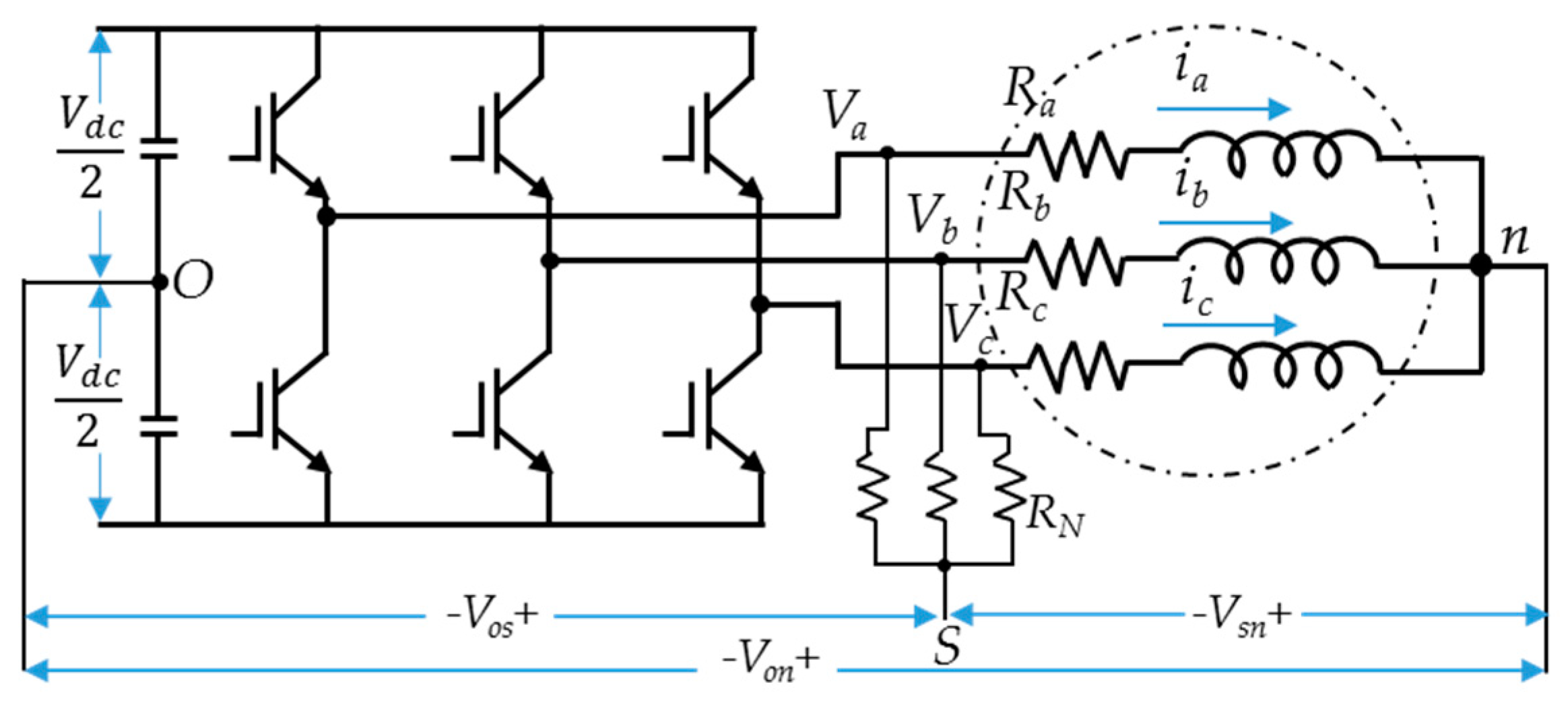
2. Modeling and Characteristics of ITSF and IDF in PMSM

Numerous modeling techniques are used to study the PMSM under ITSF and IDF. Each technique tries to simplify the analysis by making some assumptions. This section briefly explains the most common and recent fault models used in the analysis of fault diagnosis. The merits and demerits of each model and the characteristic of PMSM under ITSF and IDF are also explained briefly.

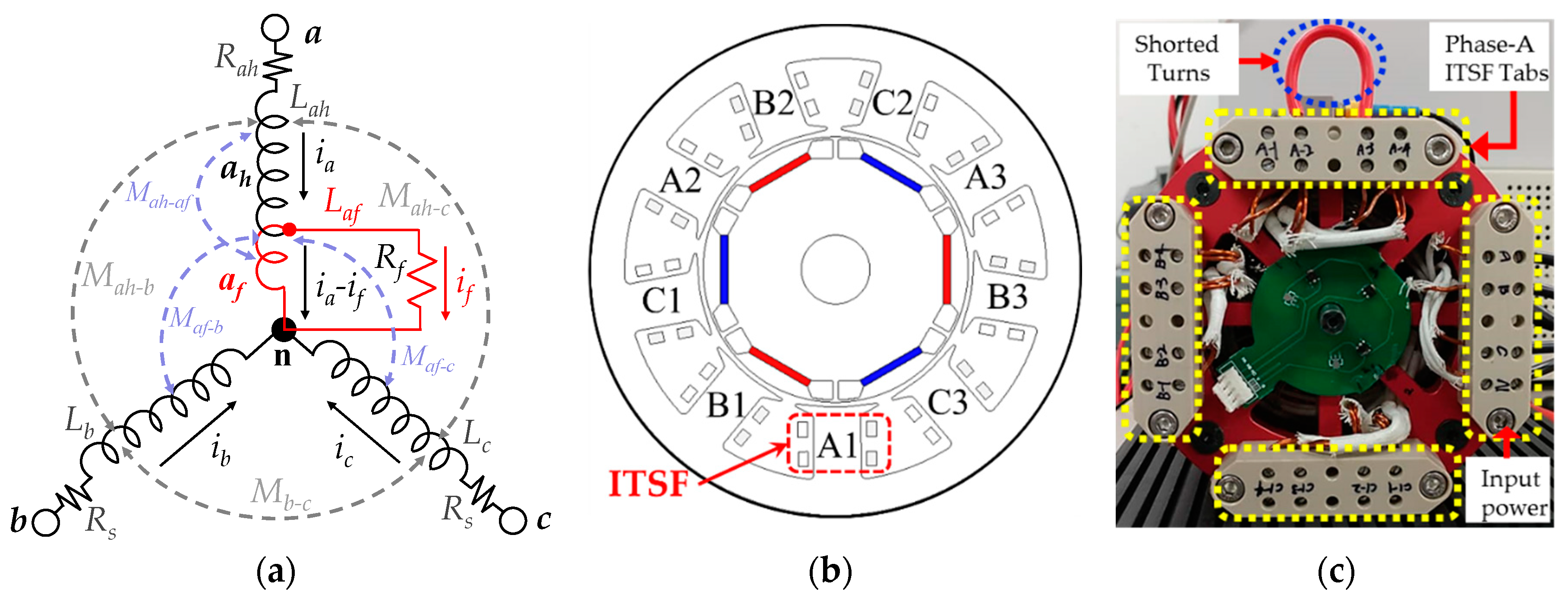
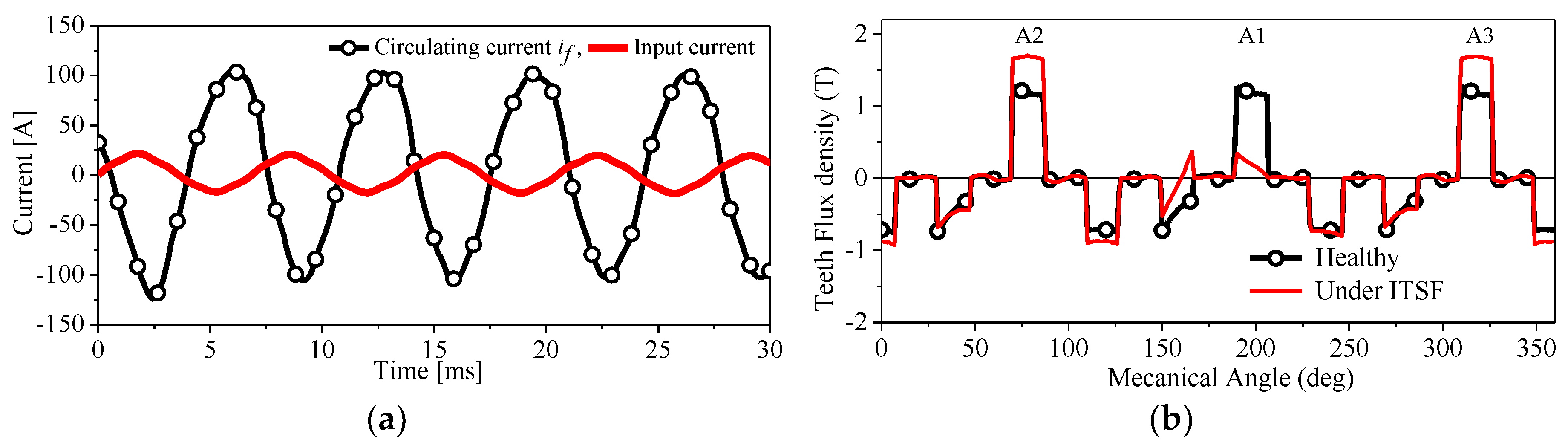
2.1. Inter-Turn-Short Fault (ITSF)

The winding insulation failure due to a short-circuit in the same phase of the machine is known as ITSF and it is one of the most frequently occurring electrical faults in the PMSM. The shorted-turns have serious implications on the motor operation and performance. Modeling and parameter identification of PMSM under ITSF is the first major step in the machine health monitoring and fault diagnosis process. Finite-Element method (FEM) based modeling is the most accurate technique to realize the shorted turns and the inverse magnetic field induced by a short-circuit fault current [17,18]. Several techniques regarding ITSF modeling and analysis have been proposed [19,20,21,22,23]. However, its simulation time is longer due to the high computational burden of FEM. Moreover, the reduced-order FEM-based machine models, such as linear PMSM, equivalent circuit, and field reconstruction method [19,20,21] based models are extremely effective to analyze the ITSF response and require relatively less time. However, all these methods require accurate implementation. Analytical models such as winding functions theory-based models, magnetic reluctance network-based models, and models based on an equivalent circuit in a stationary and rotating reference frame [22,23,24] are some of the fastest methods, which are extremely feasible to develop a generalized fault compared to considering a specific design for each individual analysis.
Equivalent circuit-based fault models are more appropriate to study the machine dynamic response under ITSF. Relaying on some assumptions, several authors have proposed different mathematical models considering various operating conditions and different fault setups [19,22,23,25,26,27,28]. In these methods, the motor parameters are measured analytically or by using the FEM-based simulation. Figure 1a shows the simple equivalent circuit of an IPMSM with ITSF in Phase-A. Here, ah represents the healthy winding turns; af represents the shorted winding turns; and Rf, and if represent the shorted turns resistance and the fault current, respectively. The values of Rf and if vary with the number of shorted turns. The mathematical model of PMSM under the ITSF condition is given in Equation (1) [22]. As can be seen, the shorted windings turn acts as an extra circuit loop coupled to flux linkages of its surrounding windings and represented as an additional phase in Equation (1). This additional faulty phase generates a reverse magnetic field and has induced back electromotive force (BEMF) eaf, self-inductance Laf, and mutual inductances with phase-B and phase-C Mah-af, Mb-af, and Mc-af. Figure 1b shows the FEM model of the motor with the shorted turns in the A1 tooth of phase-A and Figure 1c shows the case-study IPMSM. The winding tabs for shorting have a different number of turns. Due to short turns, a high current called circulating/fault current passes through the af. Figure 2a compares the input phase current and the fault current for the PMSM at full load and speed with three out of 72 turns shorted, and the fault current and input phase current are opposite in phase; thus, it generates reverse magnetic flux in the faulty slot, which opposes the main flux. Under ITSF, the healthy turns in the faulty tooth decrease, so the magnetic flux density also decreases while the magnetic flux density of healthy teeth in the same phase increases compared to a healthy condition. As can be seen in Figure 2b, the magnetic flux density of the faulty tooth (A1) has decreased, while the magnetic flux density of healthy teeth (A2 and A3) increased more than the healthy machine and saturated the slot.
[ v a h v a f v b v c ] = [ R a h 0 0 0 0 R a f 0 0 0 0 R s 0 0 0 0 R s ] [ i a i a i f i b i c ] + [ e a h e a f e b e c ] + [ L a h M a h a f M a h b M a h c M a h a f L a f M a f b M a f c M a h b M a f b L b M b c M a h c M a f c M b c L c ] × d d t [ i a i a i f i b i c ]

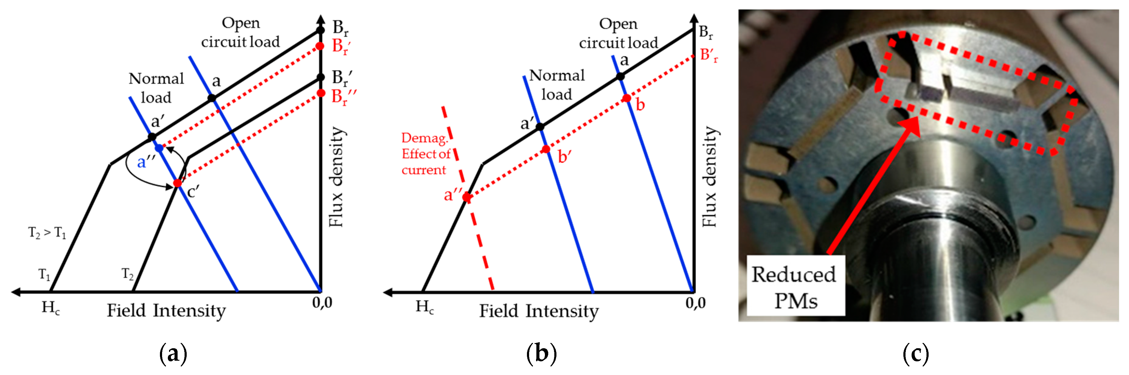
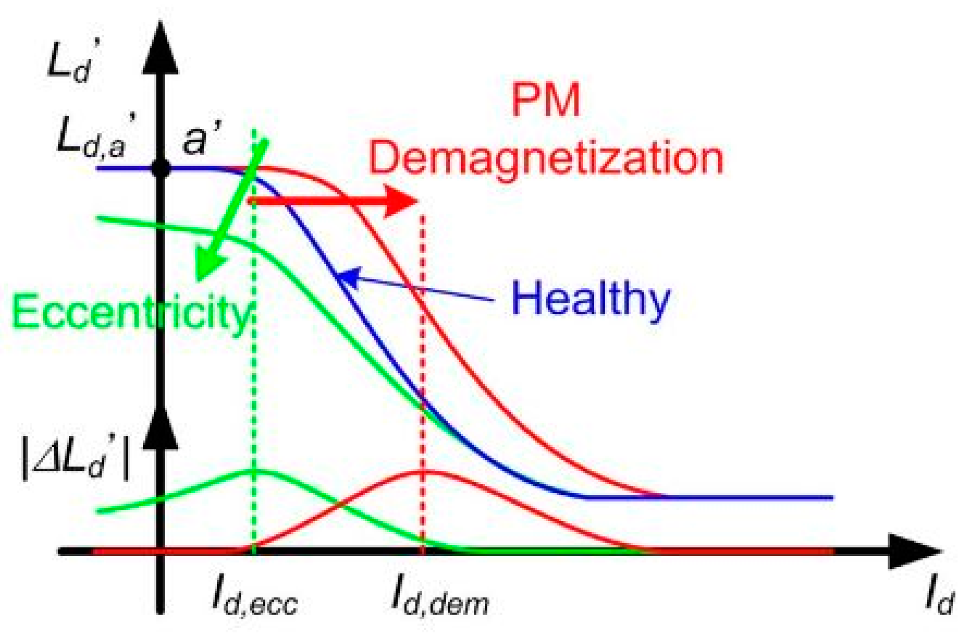
2.2. Irreversible Demagnetization Fault

Permanent magnets are generally made of a hard magnetic material, i.e., they have high coercivity and high remanence. The coercivity is a measure of how high an external magnetic field is needed to reduce the magnetic flux density inside the material to zero. However, this value does not necessarily mean that the magnetization of the material is reduced to zero. A good magnet grade will not lose any magnetization when the magnetic flux density is reduced to zero. The necessary field strength to reduce the magnetization to zero is denoted by Hic and called the intrinsic coercivity [29,30].
The properties of magnetic material change with temperature. The characteristic of PM material can be determined using its magnetization curve or the so-called B-H curve. Demagnetization is the most important characteristic in the B-H plane and it tells us how the magnetic field density changes with the demagnetization field. NdFeB and SmCo are nowadays the most popular magnets, and their demagnetization curve remains linear till knee point and soon after the knee point, it drops sharply. In the PMSMs, the intersection of the magnetization curve and the load line gives us the operating point. In the linear region, the B-H curve can slightly move up and down and this phenomenon is called “reversible demagnetization”. However, if the operating point goes beyond the linear region and crosses the knee point, then it never recovers to its original magnetizing curve and hence the residual flux density of the PM decreases. This phenomenon is called “irreversible demagnetization (IDF)”.
In Figure 3a at normal load, the machine’s operating point is a’, and it moves below the knee-point (a’’) of the curve due to the large stator current that generates the demagnetizing magnetomotive force (MMF). When the operating point reaches a’’, rather than following the original track, it follows the dotted line a’’-b’-b-Br (relative recoil permeability line) in Figure 1a, and the machine recovers to a new operating point b’ in normal conditions [31]. In [17], it has been shown that the ITSF and open phase/switch fault significantly increase the demagnetizing MMF and lead to IDF. Furthermore, the operating point can also move below the knee point during normal operation due to the increase in temperature. The residual flux density Br normally decreases when the temperature increases and the coercivity Hc increases for the ceramic PM and decreases for NdFeB and SmCo PMs. Figure 3b shows the shift in demagnetization curve for NdFeB at an increased temperature. At a higher temperature (T2), the operating point falls from a’ to c’ with a decreased flux density Br’’ under a normal load. If the temperature decreases from T2 to T1, the operating point will shift to a’’ and the curve will follow the dashed line (a’’-Br) rather than the original demagnetizing curve and hence will result in IDF [31]. Figure 3c shows the rotor of the case-study IPMSM with reduced sized magnets. The different sizes of magnets can be replaced in the rotor to realize the different severities of IDF.
Demagnetization usually occurs due to a high operating temperature, severe flux-weakening, a reverse magnetic field due to ITSF, some physical damage, an open circuit fault, and aging. IDF intensively affects the performance of a machine. It can considerably decrease the back electromotive force (BEMF) of the motor. Furthermore, IDF not only disturbs the symmetry of the air-gap flux density, stator phase current and voltage, and the generated electromagnetic torque, but also increases the acoustic noise and vibrations in the machine. In addition, the motor draws a higher current for the constant load and speed compared to a healthy machine, which further raises the temperature of the stator winding, and as a result, more flux drops under IDF in the PMSM.
Modeling of a fault is the first major step in machine health monitoring. FEM-based numerical simulation is very accurate in IDF analysis; it takes in to account the geometry of the magnetic circuit, the stator winding distribution, and the nonlinear behavior of the core. Although FEM is the most accurate among the existing modeling methods, it is computationally complex and might not be suitable for real-time analysis in many applications. Since the analytical methods based on electrical machine theory use several assumptions and need fewer elements, these methods are relatively fast. However, assumptions like neglecting core saturation, the skin effect, and the slotting effect compromise the accuracy level [32]. To overcome the shortcomings of these two methods, FEM-assisted and hybrid techniques are introduced. These methods include the field reconstruction method (FRM), lumped parameter models such as the dq-axis of the machine with detailed parameters obtained by FEM, the FEM-based phase variable model, and reluctance networks-based models. All these techniques have a reasonable simulation time with a sufficient accuracy and are possible to apply to real-time commercial applications.
FRM and reluctance network-based techniques model and analyze the single slot of the machine and therefore, takes less time compared to FEM. However, compared to other data-based methods, these techniques are still computationally complex [28]. In [33], a novel method for the surface type PM machine with a skewed rotor based on 2D-FEM is presented. Normally, for skewed rotor PM machines, 3D-FEM is used, which is extremely complex and time-consuming. The effect of IDF on a PM synchronous generator with series and parallel windings is presented in [34]. No fractional harmonic components are observed in series winding, while in the case of parallel winding, the fractional harmonics are evident.
Various types of equivalent circuit-based models are proposed in [35,36,37]. A reluctance network-based model for the PM machine is presented in [35]. In this model, all the major nonlinearities, such as the slotting effect, core saturation, and partial demagnetization, are taken into account. An analytical model using a direct solution of Maxwell equations-based method is proposed in [38]. In this method, PM is divided into different sections and the air-gap potential equation for each section is solved individually and at the end, and the summation of all sections is obtained to calculate the potential for the whole magnet. In order to consider the partial demagnetization in this method, some parts of PM are replaced by air. A system identification technique based on symbolic data for PMSM is proposed in [39]. The time series data of the motor, such as stator voltages and currents, obtained from priori tests, are used to train the algorithm for fault modeling. In [40], the dq-axis dynamic model of PMSM assisted by estimated parameters using FEM is presented. In short, different kinds of simplified models of the machine with various kinds of assumptions are possible.

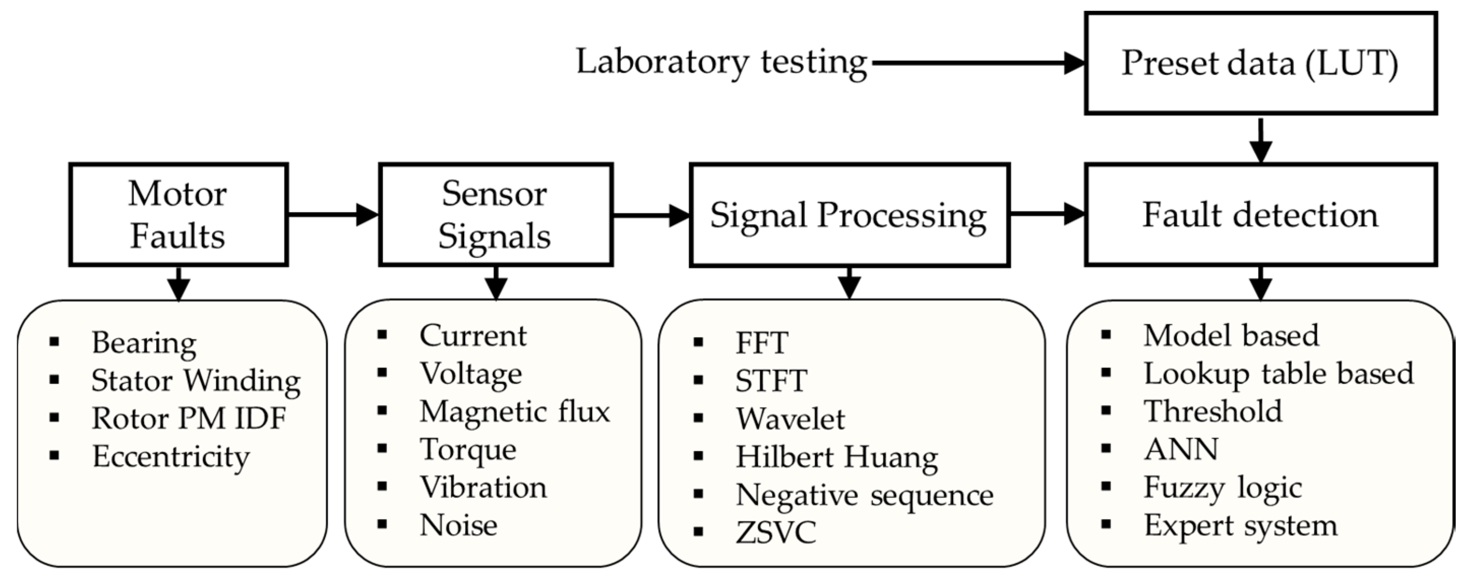
3. Fault Detection and Identification in PMSM

Machine health monitoring and fault diagnosis have a long history. With the dramatic increase in the utilization of PM type machines in various applications, fault diagnosis has gained more attention. Generally, various inputs, outputs, and other types of signals in machines and/or control drive are used as sensors to monitor and diagnose the faults. Such signals are analyzed using different signal processing approaches and extract specific information (fault signatures) that can be used to detect and identify the faults in the machine. In most of the fault diagnosis processes, initially, the data of the healthy machine is obtained and stored in a lookup table (LUT) or based on the healthy machine data, some threshold is defined for certain parameters and during the operation, the parameter is monitored and if there is some variation, the fault alarm is raised. Figure 4 summarizes different types of faults, sensor signals, signal processing techniques, and fault detection methods. It is desirable that the algorithm used for fault diagnosis should be simple, robust, accurate, and cost-effective. In addition, it should be capable of calculating the fault severity and identifying the fault location with a low computational burden. Condition monitoring of PMSMs is necessary for guaranteeing a high efficiency and reliability of the machine. In this section, the recent trends of the fault detection and identification of ITSF and the IDF are explained and compared in detail.

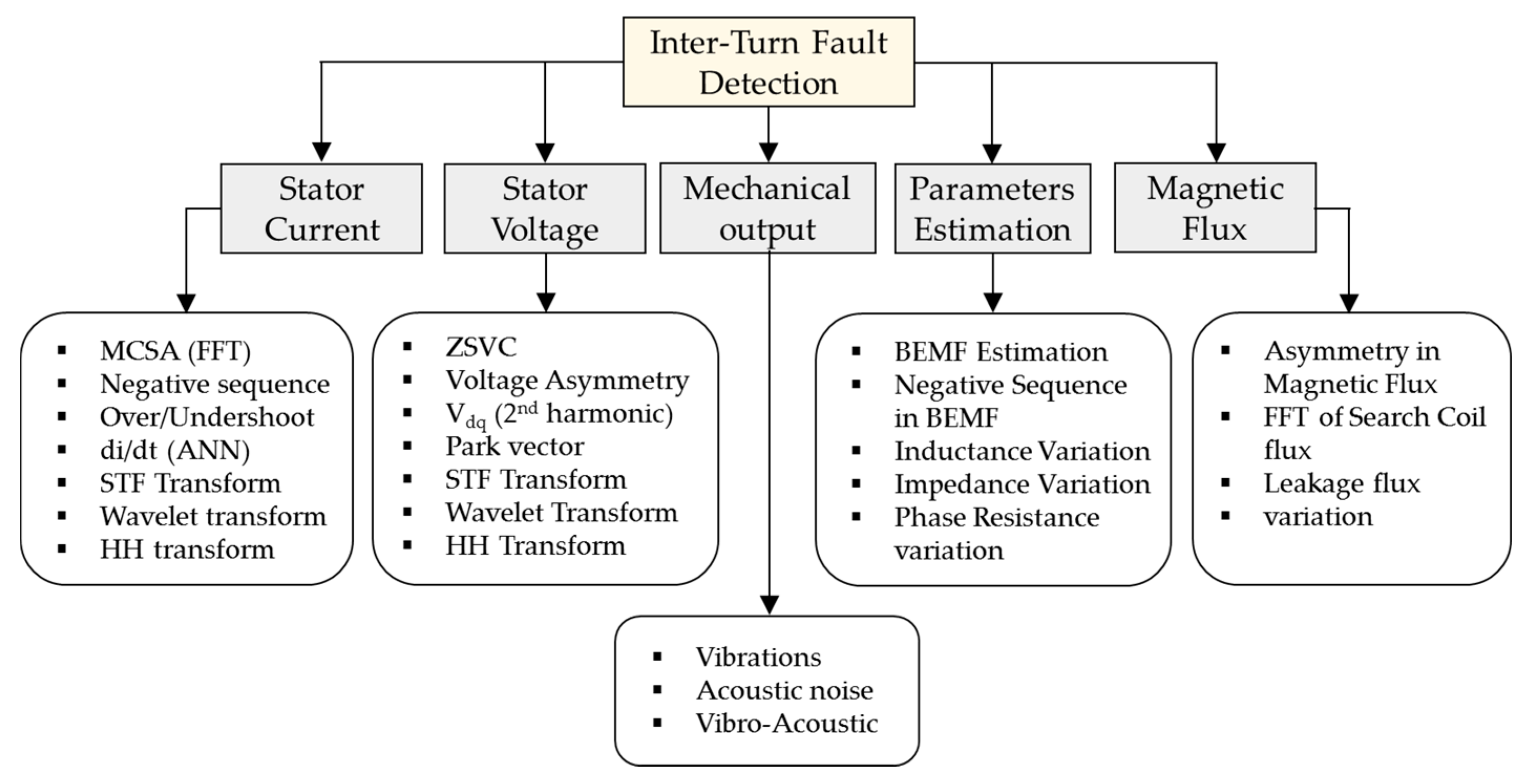
3.1. Detection Techniques of Inter-Turn-Short Fault

Various approaches and fault indicators are proposed for fault diagnosis in the motor drive system [23,24,25,26,27,28,29,30,31,32,33,34,35,36,37,38,39,40,41,42,43,44,45,46,47,48,49,50,51,52,53,54,55,56,57,58,59,60,61,62,63,64,65,66,67,68,69,70,71,72,73,74,75,76,77,78,79,80,81,82,83,84,85,86,87,88,89,90,91,92,93,94,95,96,97,98,99,100,101,102,103,104,105,106,107,108,109,110,111,112,113,114,115]. In these approaches, reference and actual values of different motor/drive parameters, instantaneous power, torque ripple, induced voltage, estimated electric parameters, vibration, and the acoustic noise spectrum, are used as fault indexes. Furthermore, several researchers have tried to combine different fault indexes to further increase the accuracy. In addition to fault detection and identification, the assessment of fault severity is the next crucial step in the machine health analysis. The change in amplitudes of various machine variables/fault indexes under any fault condition can be utilized to obtain the fault severity using advanced processing techniques. The fault severity analysis has not been studied in detailed and there is good potential for research on this topic. A detailed literature review on the ITSF detection methods is presented in this subsection. The detection methods are categorized into five groups based on the fault indexes shown in Figure 5.

3.1.1. Stator Current Analysis Based Detection Techniques

Machine current signature analysis (MCSA) has gained much popularity in the fault diagnosis field and is widely used by several researchers to monitor the motor condition during operation. The impacts of ITSF on stator-current-sequences components are investigated in various studies, such as [23,41,42]. These components are used to detect the ITSF by using different fault patterns in transient and steady state conditions. In MCSA analysis, numerous signal processing techniques, for instance, Hilber-Huang (HHT) [43], wavelet transform (WT) [44], and most commonly, fast Fourier transform (FFT) [45], are used to study the impact of the ITSF on the motor phase currents. Nowadays, FFT has become a commercial tool for fault detection in electrical motors, especially in a stationary operating condition. The main limitation of FFT is its restriction towards the applications in a non-stationary condition, i.e., time invariant signals. In [46], an algorithm is proposed to extract the faulty features out of the stator current waveform under a transient condition. In this method, the stator current waveform is divided into two parts as the first harmonic or fundamental component and the remaining harmonics caused by the fault and other disturbance. Unique features are extracted from these two parts of stator components and used for the detection of different types of faults. In [47], the effect of ITSF on the stator current and the developed torque is discussed. The harmonics pattern in the stator current due to ITSF is presented in the following form:
f I T S F = ( n ± 2 k + 1 p ) f s
where n = 1, 3, 5…, k is an integer and p is the rotor pole pair. In addition, the WT is used to analyze the characteristic of stator current under ITSF. Zhang et al. investigated stator current harmonics under ITSF and showed that the ninth harmonic which appears in the spectrum due to ITSF does not vary with the increase in load under a short circuit in winding turns, while it increases with the propagation of a fault [48]. Therefore, this harmonic can be used for the detection of ITSF. Seung-Tae et al. and Urresty et al. tracked the third harmonic in the stator current and the variation in the amplitude of the third harmonic is used as the indicator for fault detection [49,50]. It has been concluded that ITSF causes the third harmonic in the stator current and its amplitude increases with the severity of the fault. Due to the induction of PMs, the amplitude of the third harmonic depends on the speed of the motor. However, the fundamental component has no such dependency on the speed of the machine. Consequently, the ratio of fundamental and the third harmonic under ITSF on a given load keep changing with the speed of the machine. This phenomenon reduces the sensitivity of this technique. In [41] and [51], the second order harmonic in the q-axis current of a PMSM in the DQ-axis frame is used as ITSF and an inverter open switch fault as the fault index; because PMSMs with a vector control inverter are synchronous with a DQ-axis frame and are normally used to control a PMSM, the second order harmonic in the q-axis current can be easily monitored in this way. Other simple frequency analysis-based detection techniques, such as that presented by Stavrou et al. [52], and Ebrahimi et al.’s high-frequency harmonic (HF) comparison, have been used by [53]. Although MCSA- and HF-based detection techniques are non-invasive, relatively simple, and can be easily applied to the motor; however, these methods need an accurate predefined fault threshold level under all operating conditions, which can only be obtained if all the relevant data with the machine is available. To date, in MCSA, no fault model with a satisfying accuracy level has been proposed for PMSM; if an accurate fault threshold is defined, then the aforementioned methods will be extremely useful.
Moreover, the overshoot and undershoot in stator current are used for fault diagnosis in [54] and [55]. In the case of ITSF, the stator phase currents and the current demanded by the inverter drive system are different due to overshoots and undershoots in speed and current regulators. This transient phenomenon has been suggested as the indicator of ITSF detection. This technique has been tested by a six-pole PM motor with fault-tolerant isolated phases. The aforementioned method can be extended to three phase PMSM and motors having bigger mutual inductances. This method can be easily implemented and does not require any extra hardware, but the inverter nonlinearities and the speed and current regulators may affect its accuracy. In addition, the impact of core saturation, and fluctuating load and speed has not been considered.
Normally, the amplitudes of the stator phase currents are equal in the normal operation of the machine. In the case of ITSF, the amplitude of the faulty phase increases, which disturbs the balance of three-phase stator currents and this produce negative-sequence components in the current. Several techniques have compared the negative-sequence components with a preset threshold value to detect the ITSF. Arkan et al. [56] and Briz et al. [57] used negative-sequence impedance and currents through high-frequency injection. The amplitude of the negative-sequence current varies with the severity of the ITSF. This variation can be used as the indicator of the ITSF [58]. Despite its merit, this technique is highly sensitive to the variations in speed and load and also the faulty phase and the location of the fault cannot be identified. In addition, the capability of this technique in the fault separation of ITSF from other types of electrical faults, such as demagnetization and an eccentricity fault, and the robustness towards speed and load variations, should be examined.
In order to consider the time-varying signature of ITSF in a nonstationary and dynamic condition, the frequency-time analysis is proposed for the diagnosis of ITSF. In this method, the stator current signal is decomposed into a frequency-time slot and generates signatures of the fault using different transformation approaches. Short-time Fourier transform (STFT), WT, Hilbert Huang transform (HT), Gabor spectrogram, and Cohen-class quadratic distributions are the most commonly used methods for faulty machine analysis in industry applications in nonstationary conditions. STFT is a powerful tool, which is used to determine the sinusoidal frequency and phase components of a local selection of a signal as it changes with time. For extracting the fault harmonic components caused by ITSF, STFT is applied in [59]. It is observed that STFT is computationally more complex and lacks flexibility due to the fixed window-function, which is normally chosen before the operation. The fixed window-function cannot handle all kinds of variations in speed and load during operation. To overcome these issues, a different type of time-frequency distribution method WT can be applied, which has the ability to divide a wide band and non-stationary signals into a steady state time-frequency domain and time domain [59,60,61]. This means that the low-frequency components concentrate over a long range of time and HF components over a short range of time [44]. It is noted that choosing the proper wavelet-function is a crucial step in the analysis. Additionally, the WT-based methods cannot accept the transients of the machine. Therefore, for improvement, the adaptive WT-based approaches can be an attractive topic for further research [62,63,64]. HHT is another approach for frequency-time analysis used for extraction of the stator current in an ITSF condition [65]. This transformation method was proposed by Huang and it successfully overcomes many limitations of WT [66] and has been applied to analyze signals in the transient state [67,68]. Despite its edge over WT, the time-frequency patterns collected by HHT are less clear compared to WT. Moreover, HHT can only be used for extracting narrowband signals. In [69,70], an artificial intelligence-based diagnosis technique is proposed. In this method, the zero-current component and zero sequence component are obtained by summing the instantaneous phase currents and the neural network is trained with an Extended Kalman filter using fault data from both the simulation and experiments. The performance of the simulation and experimental data is compared to see the performance of the algorithm.
In the case of ITSF, the stator phase current increases, especially in the faulty phase, and this sudden boost in current can be used as a fault index. The stator current also increases with the increment in load, which decreases the speed, but the control drive adjusts the speed by increasing the current. However, the rate of increase in current (di/dt) due to the increase in load is smaller than that of the ITSF at the same operating conditions. An artificial neural network (ANN) can be used to determine the threshold of the magnitude and di/dt of the supply current for ITSF detection [71]. ANN can be trained to cover the different operating conditions of each specific machine and is able to update and reconfigure the detection algorithm quickly online during the operation. The selection of the optimized activation function is an integral part of this approach because of its effect on the training speeds and accuracy. Selection of the activation function versus the algorithm training speed can be investigated in the future. Unlike the other methods, there is no negative effect of core saturation on this index; however, the fault location identification is one of the limitations of the aforementioned method which needs to be investigated.

3.1.2. Voltage-based Detection Techniques

Several voltage-based techniques for the detection of ITSF have been proposed. Most of the voltage signature analysis-based fault detection approach depends on the different low and high order harmonics monitoring in stator current and voltage. However, the amplitude of these harmonics might be influenced by various factors, such as current feedback loops of the controller drive, variable load, and speed. The zero-sequence-voltage components (ZSVCs) may be used to detect the ITSF [72,73,74]. The ZSVC-based method seems attractive because it is free from the effect of the machine drive. Nevertheless, access to the neutral point of the motor winding is required. The ZSVC-based diagnostic approach is an attractive solution for fault tolerant schemes. Fault tolerant inverters normally utilize an additional fourth inverter leg, which is normally linked to the neutral point of the motor under a fault condition [75]. In [76], ZSVC has been examined in both transient and steady-state conditions using FFT and HHT, and it has been concluded that its first harmonic can be used as the ITSF indicator in a star-connected PMSM. To track this harmonic under variable speed and load over the entire operation region of the motor, Vold-Kalman filtering order tracking (VKF-OT) is applied [76]. The first (V0,1) harmonic tracked using VKF-OT may be approximated as
V 0 , 1 k 1 ω sin ( θ 2 π 3 ) + k 2 ω 2 cos ( θ 2 π 3 ) + k 3 d ω d t sin ( θ 2 π 3 )
where ω is the rotating speed of the motor. It has been observed that there is a linear relationship between the amplitude of the first harmonic and motor speed. Therefore, in [74], this has been utilized to estimate the severity of ITSF using HHT. Ying Fan et al. analyzed ITSF in the multi-phase machine using ZSVC in [77] and the severity of ITSF was estimated by the amplitude of the zero-sequence current component (ZSCC). An online ITSF diagnosis method for both delta and star connected motors is presented in [78]. Mathematical expressions for ZSVC and ZSCC are derived and based on the calculated fault current. A fault index is introduced and as per claim of the author, this technique is not only able to detect the ITSF, but also to identify the severity of the fault and the faulty phase. Under ITSF, the most visible change in machine variables is the imbalance in the stator voltage and current. Therefore, a neutral-point voltage-based diagnosis technique is applied to different severities of ITSF in the motor [79]. This technique can be used to determine stator voltage phase imbalance caused by different types of short and open winding faults, yet the type of fault cannot be determined.
In a motor control drive system such as vector control and direct torque control, the variation in reference phase voltages in the stationary reference frame (Va*, Vb*, and Vc*) and rotating reference frame (Vd*, Vq*, and V0*) can also be used as a fault index. ITSF causes an imbalance in these reference phase voltages and the asymmetry generated by the fault can be monitored using current controllers. This asymmetry can be used as a fault index [51,80]. T. Noileau et al. analyzed the dq-axis reference voltage (Vd* and Vq*) and concluded that the amplitude of second harmonics in the Vdq* increases with the severity of ITSF. Therefore, this can be used as an indicator of ITSF by setting a threshold [81]. Likewise, continuous WT (CWT) is used to analyzed Vq* for the detection and localization of ITSF in a BLDC (brushless direct current) motor [82]. M. Khov et al. proposed a new online ITSF diagnosis method for the non-sinusoidal BEMF of a PM machine. In this method, a new set of parameters are estimated using a recursive least square method and then calculate the structure distance between the faulty model and extended park model [83,84]. Finally, in [85], a cerebellar model arithmetic controller is used for the fault diagnosis of a large-scale PM wind generator. Voltage signal-based detection techniques are similar to current signal analysis, except the signal sensing, filtering, and isolation methods. The fault signals are very low compared to output voltage signals, so it is extremely challenging to determine them perfectly on conventional analog to digital converters due to the noise factor.

3.1.3. Parameter Estimation Based Detection Techniques

The parameters of the PM motors, such as self and mutual inductance induced BEMF, and rotor saliency, are extremely sensitive to different unwanted variations caused by various types of faults. These parameters are observed during operation to diagnose the occurrence and severity of the fault [86]. Mostly, in these techniques, the threshold values for the parameter to be monitored are initially defined through FEM simulations or by experiments. A physics-based BEMF estimation method is applied to diagnose the ITSF in PMSM in [28]. In this approach, an open loop BEMF estimator is used to extract the difference between the estimated and reference BEMF and this difference is used as a fault indicator. A current mode tracking method considering the thermal effect of the stator current is used to design an induced EMF estimator. The thermal effect helps in the prediction of the winding resistances at different operating points and severities of ITSF. In other words, the linear average value of the BEMF differences normalized with the rotating velocity is proposed as the fault indicator and can be formulated as
I T S F i n d e x = 0 t ( u d i f f ( τ t 0 ) / ( t 0 ω m ) ) d τ
u d i f f = E M F r e f . E M F e s t .
The authors claimed that their proposed technique can estimate the severity and the identification of faulty phase instantaneously and has no limitations. However, there is one disadvantage of this index, which is that the estimated BEMF can be affected by several factors, such as dead time between the upper and lower switch of the inverter leg, inverter switching frequency, the voltage drops in the semiconductor switch, and the offset of the current transducer, which might compromise the accuracy. In [87], a diagnostic strategy for an EV drive system is formed by integrating online and offline ITSF detection techniques. In an online detection method, an iterative observer is used to estimate the negative sequence of BEMF, which can be implemented on hardware in different applications. Normally, the online fault detection method has a poorer performance at low speed, which can be balanced by using the integrated offline technique that in turn can help in improving the performance in the low-speed region.
ITSF directly affects the magnetic flux distribution due to the generation of the inverse magnetic field in the shorted turns of the faulty phase. Therefore, a huge change in an electrical parameter such as the self-inductance and mutual inductance occurs. Gu used winding function theory in [88] to analyze the variations in self- and mutual inductances of a BLDC machine due to ITSF. In [89], the difference in the increased inductance curve between a healthy and faulty motor is used for ITSF diagnosis considering the saturation effect of the core. This method detects the type and severity of fault based on the variation in inductance curve. Different types of PMSMs are analyzed and a K-Nearest Neighbor (KNN) scheme is used to categorize the data obtained from simulation and experimental tests to distinguish between ITSF and an eccentricity fault, as well as to estimate the severity of each fault. In [90], a Volterra Kernel Identification-based technique is applied to diagnose the ITSF in a PM generator. In this method, the stator branch voltage and stator unbalanced current are analyzed to diagnose ITSF. Kim et al. compared the ITSF characteristics of interior type PM (IPM) and surface type PM (SPM) BLDC motors using winding function theory in [91]. A fault impedance-based modeling for magnetic characteristic analysis is proposed for IPM type BLDC in [92]. The input phase current, circulating/fault current, BEMF, torque density, magnetic flux distribution, and performance of the machine are analyzed based on the proposed model and the input impedance is used as the indicator of ITSF [93]. Stator winding impedance variation in PMSM under ITSF and eccentricity fault is analyzed in [94]. The phase impedances are monitored at a standstill condition before or after the operation. It has observed that the effects of ITSF and eccentricity on impedance variations have different patterns and these patterns are used for the separation of both types of faults. A theoretical approach is used to make a dynamic model of PMSM under ITSF in [95], and [96] used a permeance network to study the ITSF. In these two approaches, the author attempted to estimate the machine parameters under a fault condition to avoid the computationally complex FEM. Furthermore, these approaches can be used for various ITSF locations in the slot considering leakage flux and winding distribution. Likewise, Vaseghi in [58] and [97] analyzed an SPM motor under ITSF to estimate phase resistance and inductance; a phase variable-based model using FEM for a PM machine is suggested for the estimation of the motor parameters with respect to the ITSF location and severity [98]. The parameter estimation-based detection technique has also been used for a multi-phase PMSM in [99].
High-frequency (HF) signal injection-based algorithms for the detection of ITSF are proposed in [100] and [101]. In these techniques, an HF voltage signal in orthogonal space is superimposed on the reference voltage and the variation in the incremental inductance of the machine is monitored. The variation in the motor saliency component is identified from the measured stator current and this estimated saliency is used as the fault index for ITSF. Likewise in [102], a pulsating-type voltage signal is superimposed on the d-axis of an IPM machine. In this method, a pulse voltage is injected on the d-axis and the induced current ripple is used to monitor the change in d-axis inductance under ITSF. This method is not affected by saliency harmonics and is valid under both normal operation and standstill conditions. A similar approach using indirect flux estimation and online reactance measurement for PMSM can be found in [103]. Furthermore, [104] used two open-loop observers and Particle Swarm Optimization (PSO) to estimate the q-axis inductance and current of faulty phase. A feedforward neural network-based method is applied to diagnose a fault in the low power hub motor in [105]. The aforementioned diagnosis trends show that under ITSF, the electrical parameters such as BEMF, resistance, and inductance variation, provide signatures of the fault presence in the system. The main edge of the parameter variation-based diagnosis method is its easy implementation and there is mostly no need for extra hardware. With a similar hurdle like the MCSA approach, the discernment of ITSF and other types of fault is possible due to similar fault indicators. For example, in an IDF condition, we get similar indicators on the BEMF for both ITSF and IDF. Thus, further analysis is required to discover the forthcoming fault indicators.

3.1.4. Search Coil Based Detection Techniques

Search coil and flux sensor-based diagnosis is a very reliable method for the detection of ITSF. By monitoring the magnetic flux, the detection and location of ITSF can be easily identified. Dealing with winding configuration dependency and fault type discernment is also relatively easier using a search coil. However, this method needs hardware-based modification in the machine, and it needs to install additional coils, which increase the difficulty of motor design. In radial flux machines, ITSF causes asymmetry in magnetic flux distribution and leakage in axial flux. In order to measure the variation in this leakage flux, four search coils are employed [106]. Generally, there is an ample amount of axial leakage flux so that the search coils are mounted externally to the motor frame. By analysis, the following pattern of harmonics has been introduced for the detection of ITSF:
f B , a x i a l = f s ( k ± n p )
where B represents the special harmonics. As the ITSF disrupts the symmetry of the flux, in the end, the winding region (due to a reverse magnetic field caused by shorted turns), the location of ITSF is found out through measuring the localized magnetic field at the end winding region. A search coil is not expensive and can be easily applied to different types of motors. Furthermore, for measurement of the proposed harmonics, a simple electronic circuit can be used. However, this method cannot be used in nonstationary speeds and load conditions. In [107], a search coil-based ITSF detection algorithm is proposed for BLDC machines. In this method, an additional detection coil is wound on motor teeth and the terminal voltage across that coil is monitored. Chai et al. presented a comparison of ITSF for two-phase and three-phase machines using a search coil in [108]. In [109], various faults using a search coil are analyzed, including ITSF. Optimizing the location of the search coil, its number, and the adequate parameters for investigation for the severity of the fault can be a future research topic.

3.1.5. Vibration and Acoustic Noise-Based Detection Techniques

Vibration analysis is the better choice for mechanical failures and can be used for electrical failures as well due to additional fault-related torque ripples [110]. However, it is very sensitive to external vibrations and environmental disturbance, which can considerably alter the accuracy of the fault diagnosis process [111]. Both mechanical power output and vibration-related diagnosis techniques need additional sensors, which further increases the fault diagnosis implementation cost. As discussed in the earlier subsection, ITSF disturbs the symmetry of the machine due to reverse magnetic flux, which results in vibrations and acoustic noise. If the severity of the ITSF is high, then this noise can be audible. Some studies used the specific spectrum of vibration and acoustic noise as the indicators of faults. However, this method is relatively less common due to its cost effect and accuracy. In [112], the mechanical oscillation due to ITSF and an open phase fault is analyzed. In this method, two vibration (piezoelectric) sensors are placed on the external body of stators to monitor the mechanical oscillations due to ITSF and open phase faults. These faults result in some additional vibration components on the frequency spectrum of mechanical vibration, which are considered as fault signatures and used for fault detection. Likewise, [113] also used the vibration spectrum to detect the IDF and ITSF fault. A spectrum of mechanical power for ITSF detection is presented in [114]. According to this analysis of the machine, parameters will eventually be affected due to ITSF, irrespective of controller type.
Vibro-Acoustic fault diagnosis for a hybrid electric vehicle is presented in [115]. The vibration and acoustic noise spectrums are collectively analyzed and this data is then applied to the neural network to train the algorithm. Eighteen different components are extracted from each spectrum and those features are used as fault indicators.

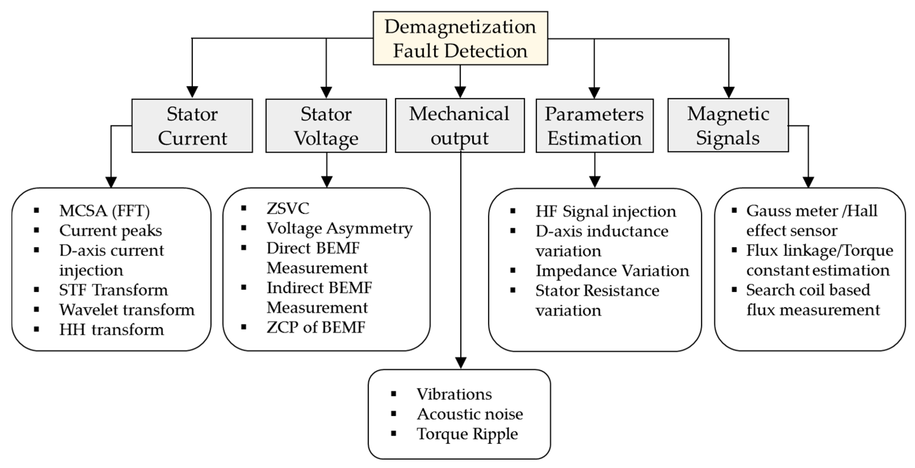
3.2. Detection Techniques of PM Irreversible Demagnetization Fault (IDF)

Several methods for the IDF have been proposed on the basis of different fault indicators. In this section, the most common and recent trends of irreversible demagnetization fault detection and identification in PM machines in steady state/stationary operation and dynamic/nonstationary operation are summarized based on their sensor signal and/or signal processing approach. Stator current, voltage, parameter estimation, magnetic signals, and torque ripple-based fault indicators are discussed one by one. Figure 6 shows the summary of all categories of fault detection technique to be discussed in this subsection. The basic idea of each index, implementation method, strength, and weakness of each method are discussed in detail.

3.2.1. Stator Current Based Detection Techniques

Almost every fault disturbs the symmetry of magnetic flux in the PMSM, which results in torque and speed variations in the motor. These variations are reflected in the stator current and the health of the motor can be easily determined by studying the so-called MCSA during operation or offline at standstill. As discussed in the previous subsection, MCSA does not need any extra sensors or hardware and can be easily implemented on modern microcontrollers. IDF causes these harmonic components and the high severity of a fault increases the magnitude of these harmonics. Therefore, monitoring the magnitude of these harmonics is the proper criterion for fault detection [13,116,117]. Generally, FFT is applied to analyze these harmonics and for the detection of IDF. The fractional harmonic pattern due to IDF and its amplitude can be written in the following form:
f I D F = ( 1 ± k p ) f e k = 1 , 2 , 3 ,
A I D F = V s l o t K I D F k π sin ( k π 2 p )
where fIDF, fe, Vslot, and KIDF are the demagnetization frequency, fundamental frequency, BEMF induced in a single slot, and demagnetization severity, respectively. Based on stator current harmonics, some studies on IDF detection for PMSM and BLDC motors have been suggested in [117] and [116]. In these methods, the harmonic pattern given in Equation (7), and its amplitudes given in Equation (8), in the stator current caused by the IDF are monitored and used as fault indicators. This approach is very appropriate in stationary conditions, but not applicable to a small load, fluctuating load, and speed. In addition, those harmonic components that appear for a short interval of time might be missed by FFT in frequency spectrum analysis. Unlike partial demagnetization, uniform demagnetization does not cause any asymmetry in the machine, and hence, no additional harmonics appear in the stator current. In addition, such harmonics can be caused due to some other reason, such as a fluctuating load and static eccentricity fault. Despite that, according to [118], even though both static eccentricity and partial demagnetization faults cause similar harmonic in the frequency spectrum, the difference in the appearance of these harmonics and dynamic behavior in two different types of faults can be used for distinguishing the partial demagnetization and static eccentricity. Unlike the partial demagnetization, in static eccentricity, the inductance profile varies due to the non-uniform air-gap. However, practically due to inherent manufacturing defects in PMs, these harmonics may appear, which makes this method difficult to implement. Moreover, in some winding configuration of the motor, in the faulty machine, the multiples of the third harmonic in mechanical frequency may cancel out. Therefore, for reliable fault diagnosis, it should be taken into account [119]. In the case of concentrated wound PMSM, the harmonics due to a fault in induced voltage appear in the individual coil, but the combined effect of whole windings cancel each other out and the net effect is zero. Therefore, similar to uniform demagnetization, in concentrated wound PMSM, the fault harmonics in induced voltage will not appear. In [73], the effect of IDF severity upon the zero sequence component of the stator current has been studied.
Advanced signal processing techniques can be applied to overcome the reliability issue of MSCA in transient and nonstationary conditions [120]. Similar to ITSF, in the STFT, WT and HHT can be applied to diagnose IDF. In [121], using STFT, the signal is divided into various parts using a fixed window. The selection of the appropriate type and size of window is crucial in this method and should be selected according to application and frequency components, which are normally unknown at the start of the analysis. In addition, in the selection of the window, the resolution of time and frequency is compromised [122]. Normally, this technique is suitable for steady-state and stationary conditions. On the other hand, WT is a multi-resolution signal processing technique and it can overcome this limitation of STFT. In [123], the current spectrum of a PMSM is analyzed and CWT and the discrete wavelet transform (DWT) are applied for the detection of IDF. Despite its merits, WT also needs to determine the parameters, including wavelet type. In [40], CWT is applied to the starting stator current of PMSM to diagnose IDF in EVs. Furthermore, another time-frequency distribution technique for monitoring harmonic components is based on quadratic distribution. Unlike the linear distribution method, which divides the signals based on its initial parts, this technique divides the signals based on energy distribution [124]. The most appropriate method of this class is Wigner-Ville transform (WVT) [121]. This method has a high resolution compared to earlier methods. HHT is also a competitive candidate in the nonstationary time-frequency signal analysis, but the drawback of this method is that it can only be applied to the sinusoidal signals. However, most nonstationary signals are multi-frequency components. To remove this hurdle, HHT uses empirical mode decomposition (EMD) to divide the signal in the time-domain into a restricted known number of periodic functions, which is known as intrinsic mode function (IMF) using the sifting process, in which HHT is applicable. In [43] and [123], HHT is applied to detect the IDF in the PMSM under variable speed. The IMF obtained EMD can have a particular physical concept, which helps to analyze more transient and time-varying signals.

3.2.2. Voltage-Based Detection Techniques

The reduction in magnetic flux due to demagnetization has an extremely large impact on motor BEMF and can be a fault indicator. The BEMF of the motor can be measured in either a direct or an indirect way. In a direct way, it can be measured in a generating mode of the machine across the open circuit terminals. Therefore, this method based on direct measurement can only be used in an offline condition [125,126]. In [127], several methods, including BEMF-based methods, are used to diagnose IDF. In order to measure the BEMF in an online state, some indirect analytical model-based strategies are suggested. In this side, the inverse transformation method [36] and spatial harmonic-based methods [128,129] are used. Like other model-based techniques, the proposed technique is also sensitive to parameter variations and operating temperature, which can reduce the accuracy and reliability of the algorithm.
The synchronously rotating harmonics in the air-gap consist of all odd harmonics, among which the most effective harmonic is the third harmonic, which generates the zero sequence voltage in phase voltage [6]. Thus, instead of BEMF, the triplen harmonic can be tracked in terms of ZSVC. If the neutral point of the PMSM is accessible, then the zero sequence component can be easily extracted and analyzed for fault diagnosis. There are three different methods for measuring the neutral point voltage, depending upon the availability of the motor neutral point and the distance between the machine and inverter. Figure 7 shows a schematic diagram of inverter-fed three phase PMSM with both the neutral point of PMSM and the artificial resistor network-based neutral point. The ZSVC can be measured across three different points: VOS (voltage between common point of the dc-link and the artificial common point made by resistor network), VSn (voltage between the artificial common point and the neutral point of the motor windings), and VOn (voltage between the dc-link and the machine neutral point). If the motor is far from the inverter, then the VOS can be measured using a filter [130].
The IDF may cause a different number of harmonics in the BEMF and phase currents depending on the winding topology. But it has been observed that no matter what the winding topology is, the BEMF of a PMSM with IDF will always reduce, and consequently, the neutral point voltage will also decrease. Thus, this phenomenon can be used to measure the severity of the IDF. In [131], the following assumption is made. First, the rotor of a healthy surface type PMSM is supposed to have n number of identical magnets with the same remanence Br. Second, it is assumed that the BEMF voltage in a phase winding ephase is proportional to the number of magnets and also to the angular speed of the rotor. If ntotal represents the total number of PMs in a PMSM and neffective the number of effective PMs, then in the case of IDF, neffective < ntotal and BEMF under the fault is estimated as follows:
e f a u l t y ( t ) = n e f f e c t i v e n t o t a l e h e a l t h y ( t ) = k e h e a l t h y ( t )
where k is the severity index of demagnetization which can be measured using the ZSVC technique given in [131].
k = V O n , f V O n , h
where Von,f and Von,h are ZSVC for the faulty and healthy motor, respectively. The drawbacks of this method are that it cannot be implemented without accessing the neutral point of the motor. However, there are other methods, such as the fault tolerant machines [132,133], sensorless control techniques for PMSM [6], and sensorless control of BLDC [130], that also require the neutral point. Therefore, access to the neutral point is generally justified.

3.2.3. Parameter Estimation Based Detection Techniques

In PM-type machines, the variation of parameters due to core saturation and operating temperature are considered their weak side. However, in health management of the machine, this variation can be used for the detection and measurement of the severity of the fault. The signal injection-based parameter estimation technique not only solves the problems of temperature sensitivity and saturation, but also enables us to estimate fault severity. This technique can be used in all types of motors operated by the inverter; in this technique, a controlled signal with an adjustable amplitude and frequency is injected in the motor and the variation of the impedance pattern is observed [134]. The signal injection to the faulty machine results in some additional pattern in other signals of the motor, which ensures the presence of a demagnetization fault. In [31], a pulsating field signal is injected at different angular positions, and variation in current peaks caused by a change in the degree of saturation due to IDF is monitored at a standstill condition. Variation in d-axis inductance due to IDF by applying a direct-current and alternating current simultaneously is presented in [135]. Furthermore, the stator reflected PM high-frequency resistance variations by applying a high frequency pulsating sinusoidal voltage signal-based approach is presented in [136].
Differential inductance variation-based fault IDF diagnosis is considered an accurate method in a standstill condition. This inductance can be obtained by calculating the slope of the λ-I curve at any point. According to [135], this inductance can be written in the following form:
L d = d λ d / d i d
An AC signal is injected in a d-axis direction to saturate the machine and the reactance is then calculated from the fundamental component of the voltage and the variations occurring in the d-axis inductance can be used as the fault index. It requires a high magnitude of the direct current field to saturate the core under an IDF condition. Figure 8 shows the variation in Ld vs Id in healthy, IDF, and eccentricity faults. The difference between both the curves of the fault is compared to the healthy case (ΔLd); its peaks are used to separate the faults. This method has several advantages, such as it does not require any extra hardware, it is easy to implement, it has a high sensitivity, independent from operating conditions, and it has a low cost, independent from other type of rotor faults, and can possibly detect both types of partial and uniform demagnetization faults. Despite this, this method cannot monitor the PM quality continuously and therefore, this technique can only be applied to the system which stops and starts frequently.

3.2.4. Magnetic Signal Based Detection Techniques

Investigation of asymmetry in magnetic flux distribution caused by partial or uniform demagnetization is the primary step in the IDF diagnosis process. Generally, the precise measurement of magnetic flux is only possible by direct measurement using a Gaussmeter [31] and/or Hall Effect sensor [39,137]. However, the direct measurement approach is unable to measure the magnetic flux online and in many cases, the machine needs to be dismantled, which might not be possible in many applications. Moreover, these techniques cannot be applied to IPM-type machines. To overcome these issues, some indirect motor model-based techniques are proposed. In these techniques, parameters of the machine, the output, and other signals such as magnetization factors [138], flux linkage of the machine [39,117,139], torque constant [116], and stator teeth flux in multi-phase machines [140], are estimated. In order to estimate these parameters, the measured voltage and current are used as input variables. For example, the BEMF of the BLDC machine is estimated in the following way:
e ^ = V m 2 R s I d c
where Vm is the mean value of the input supply voltage, Rs is the stator resistance, and Idc is the dc link current. The torque constant of the BLDC motor can be obtained by dividing Equation (12) by the rotational speed of the rotor.
K ^ t = ( V m 2 R s I d c ) / ω r
The estimated values of the torque constant are used to find the quality of PM [116]. Although these techniques have no dependency on other parameters of the machine, the core saturation and effect of operating temperature on stator inductance and winding resistance can still affect the accuracy of the algorithm. In addition, low severities of fault might not be detected using this method.
Search coil-based measurement is another direct and online flux measurement method. In this method, an additional coil is inserted in the specific location according to fault type. In [109], inserting a search coil on each tooth is suggested. Search coil measures the armature magnetic flux and the flux generated by PM in the linear unsaturated region. In order to design a reliable and noise-free detection algorithm, it is necessary to measure the main component of the induced voltage in the winding using a linear time-invariant filter and then the components due to PM flux and armature flux are decoupled. As the voltage of the search coil is measured for a short period of time, it will not be affected by the transients of the motor. The component of magnetic flux measured by 12 search coils in PMSM under healthy and IDF conditions at a specific instant is given in Figure 9.
The reduction in magnetic flux due to partial and uniform demagnetization faults can be measured accurately using this method because the speed and load transients have no effect on the fault detection algorithm and there is no need to use complex and advanced transformation or pattern recognition methods. In addition, the severity of the fault can also be determined, and these methods can be applied to other types of faults, such as a static or dynamic eccentricity fault and ITSF.

3.2.5. Vibration and Acoustic Noise-Based Detection Techniques

Vibration analysis in PM motor health monitoring is a non-intrusive technique which is widely used for fault detection and similar to signal analysis, several commercial applications and industries utilize it. The machine current and voltage signal analysis methods are sensitive to electrical failures and vibration analysis is sensitive to mechanical failures. Partial demagnetization causes asymmetric and unbalanced radial forces, which result in huge vibration and audible noise. To analyze the pattern of this vibration, a piezoelectric vibration sensor needs to be installed on the motor stator. In case of severe noise, acoustic noise-based analysis can be utilized as an additional approach. In [141], the displacement of the shaft due to a partial demagnetization fault is analyzed. The change in shaft trajectory severely deteriorates the machine performance and leads to premature aging or IDF. In [142], a multi physic analysis based on the acoustic behavior of the PMSM under IDF and an eccentricity fault is presented. Different force harmonics in the stator teeth are analyzed and it is observed that under IDF, the amplitude of these harmonics is considerably high compared to a healthy machine, so these harmonics can be monitored to diagnose the IDF.

3.2.6. Torque Ripple Based Detection Techniques

The effect of a demagnetization fault is directly reflected in the torque profile of the machine. The direct analysis of the torque requires an expensive torque sensor, which is mostly not present in motor control drive systems. The indirect approaches like signal analysis are sometimes used to study the fault harmonic components in the torque profile. The electromagnetic torque of PMSM is developed by the interaction between the stator winding field and the rotor PM field in the air-gap. IDF distorts the distribution of magnetic flux density in the air-gap, which results in a considerable increase in the torque ripples and increases the amplitude of slot harmonics. These harmonics like other frequency-based methods are highly sensitive to the degree of fault and motor speed and load. Therefore, in [143], the time domain characteristic of torque is used to extract the distortion caused by IDF. The time delay embedding-based technique is used here, which is capable of detecting the distortion component in the time series data of the torque. In this method, the torque profile is transformed and reconstructed for the possible distortion caused by a fault.

4. Summary and Discussion

After a detailed literature review of ITSF and IDF diagnosis, one thing is evident, which is that researchers have tried to extract every indication caused by the fault in both the time and frequency domain and analyzed it in detail using various signal processing techniques to diagnose faults in the machine. Table 1 and Table 2 show the summary and comparison of the aforementioned techniques for ITSF and IDF, respectively. The comparison is carried out based on the strengths and weaknesses of each method, such as the ability to detect the fault in an online or offline condition, detecting uniform and/or partial demagnetization, estimating the severity of the fault, invasiveness, sensitivity to other faults or other disturbances in the system, the capability of detecting more than one fault, and the separation of them. In Table 1 and Table 2, VH stands for “very high”, H for “high”, M for “medium”, L for “low”, ABOFN for “affected by other faults and noise”, Inv “invasive”, PD for “partial demagnetization”, UD for “uniform demagnetization”, and Ref. for “reference”.
MCSA produced the greatest number of indexes and was the easiest method to implement, but faces many difficulties in terms of accuracy and reliability. It can be a good choice for specific applications with known parameters and stationary conditions. Voltage-based methods, especially the ZSVC, are a better option compared to MCSA in terms of sensitivity and reliability. Also, they are less affected by other faults and the variation in speed and load, relatively. However, they can only be applied to a machine with access to a neutral point. Flux measurement-based methods are more practical methods, especially for IDF, because they can diagnose both uniform and partial magnetization and represent a reliable method for both ITSF and IDF. The search coil-based method is the most reliable technique, and with detection of the fault, it can find the location of fault as well and it has no dependency on the machine winding configuration.
In transient and nonstationary conditions, fault diagnosis without using advanced time-frequency analysis is almost impossible. However, the main problem in the time-frequency analysis is the availability of accurate data and the computational burden of the algorithm. Due to the adaptive nature of the HHT, it does not require any preset data before analysis, but it has a relatively low resolution. HHT is the best option where the high speed of detection is not required and spreading of the fault is not an issue. HHT is the best candidate for IDF detection. On the other hand, in the case of ITSF, earliest detection is considered the best because ITSF spreads very fast. The computational burden of DWT is relatively lower and it hence has a faster speed. Therefore, DWT can be applied for the detection of ITSF. The selection of time-frequency analysis technique highly depends upon the conditions and applications.

5. Suggestion for Future Work

An immense amount of work has already been done in the area of fault diagnosis. However, the reliability and accuracy still need to be addressed. For instance, the popular MCSA approach needs further study to explore the integral fault signatures or combine the existing indexes to ensure robustness of the diagnostic scheme. In addition, the fault location, machine structure, and the effect of the control drive on the fault harmonic components in open and closed-loop control should also be considered to further enhance the reliability at different operating conditions. Moreover, estimating the fault severity, the post-fault life of the machine, mitigation of fault, and ultimately fault tolerant control can be a future research area.
Most of the proposed algorithms are for a medium and high severity of demagnetization, and except for BEMF-based techniques, the rest of the techniques are almost unable to detect small demagnetization, so this side also needs attention. Moreover, the diagnostic mechanism of the multi-phase machine is also a less studied research area.

6. Conclusions

A detailed review of ITSF and IDF diagnosis for PMSM is presented in this paper. The main challenges in ITSF are its early detection to prevent it from spreading, identifying the fault location, and estimating the fault severity. In IDF, discriminating the partial and uniform demagnetization, discriminating the fault signatures from other faults, such as an eccentricity fault, and detecting IDF in dynamic or nonstationary conditions, are challenges.
To meet these challenges and achieve a high reliability in machine health analysis, efficient techniques must be applied. Motor current and voltage analysis are the most popular techniques due to noninvasiveness, less computational burden, and easy implementation without any extra hardware. However, these methods face many robustness issues; other techniques such as signal injection, search coil, and ZSVC-based methods show more robustness. Generally, a method based on BEMF and flux measurement is more accurate and reliable.
Dealing with faults in transient and nonstationary conditions, the time-frequency analysis of the fault signatures is mandatory. STFT, WT, and HHT are common techniques for time-frequency analysis in machine fault diagnosis. The required resolution, computational complexity, linearity/nonlinearity of the problem, and intended frequency basis are different important aspects of these techniques for various applications. Furthermore, the fault signatures are normally highly dependent on the location and operating condition of the machine and using one type of signature may not provide accuracy at all operating conditions. Therefore, further research is required to develop techniques based on multiple fault indexes to ensure accuracy and reliability at every operating point.

Author Contributions

This work is the combined effort of both of the authors. Z.U. collected the published literature about the fault diagnosis and wrote the initial manuscript. J.H. revised the manuscript and added his concluding views.

Funding

This research received no external funding.

Acknowledgments

This work was supported by Industrial Strategic Technology Development Program of Korea Evaluation Institute of Industrial Technology (KEIT) (No. 10062426) and was supported by the Korea Institute of Energy Technology Evaluation and Planning (KETEP) and the Ministry of Trade, Industry & Energy (MOTIE) of the Republic of Korea (No. 20168530050030).

Conflicts of Interest

Authors declare no conflict of interest.

References

  1. Zafarani, M.; Bostanci, E.; Qi, Y.; Goktas, T.; Akin, B. Inter-turn Short Circuit Faults in Permanent Magnet Synchronous Machines: An Extended Review and Comprehensive Analysis. IEEE J. Emerg. Sel. Top. Power Electron. 2018, 6, 2173–2191. [Google Scholar] [CrossRef]
  2. Faiz, J.; Mazaheri-Tehrani, E. Demagnetization modeling and fault diagnosing techniques in permanent magnet machines under stationary and nonstationary conditions: An overview. IEEE Trans. Ind. Appl. 2017, 53, 2772–2785. [Google Scholar] [CrossRef]
  3. Zhao, K.-H.; Chen, T.-F.; Zhang, C.-F.; He, J.; Huang, G. Online fault detection of permanent magnet demagnetization for ipmsms by nonsingular fast terminal-sliding-mode observer. Sensors 2014, 14, 23119–23136. [Google Scholar] [CrossRef] [PubMed]
  4. Ullah, Z.; Kim, K.-T.; Park, J.-K.; Hur, J. Comparative analysis of scalar and vector control drives of IPMSM under inter-turn fault condition considering nonlinearities. In Proceedings of the 2015 IEEE Energy Conversion Congress and Exposition (ECCE), Montreal, QC, Canada, 20–24 September 2015; pp. 366–372. [Google Scholar]
  5. Gieras, J.F. Permanent Magnet Motor Technology: Design and Applications; CRC Press: Boca Raton, FL, USA, 2009. [Google Scholar]
  6. Liu, J.; Zhu, Z. Improved sensorless control of permanent-magnet synchronous machine based on third-harmonic back EMF. IEEE Trans. Ind. Appl. 2014, 50, 1861–1870. [Google Scholar] [CrossRef]
  7. Ruoho, S.; Kolehmainen, J.; Ikaheimo, J.; Arkkio, A. Demagnetization testing for a mixed-grade dovetail permanent-magnet machine. IEEE Trans. Magn. 2009, 45, 3284–3289. [Google Scholar] [CrossRef]
  8. Kim, K.-C.; Lim, S.-B.; Koo, D.-H.; Lee, J. The shape design of permanent magnet for permanent magnet synchronous motor considering partial demagnetization. IEEE Trans. Magn. 2006, 42, 3485–3487. [Google Scholar] [CrossRef]
  9. Hannon, B.; Sergeant, P.; Dupre, L. 2-D analytical subdomain model of a slotted PMSM with shielding cylinder. IEEE Trans. Magn. 2014, 50, 8101410. [Google Scholar] [CrossRef]
  10. Wang, W.; Yang, F.; Lun, S. The cooling system design and performance analysis of the disc type permanent magnet synchronous motor. In Proceedings of the 2013 IEEE International Conference on Vehicular Electronics and Safety (ICVES), Dongguan, China, 28–30 July 2013; pp. 202–205. [Google Scholar]
  11. Sjökvist, S.; Eriksson, S.J.E. Investigation of permanent magnet demagnetization in synchronous machines during multiple short-circuit fault conditions. Energies 2017, 10, 1638. [Google Scholar] [CrossRef]
  12. Kaufhold, M.; Aninger, H.; Berth, M.; Speck, J.; Eberhardt, M. Electrical stress and failure mechanism of the winding insulation in PWM-inverter-fed low-voltage induction motors. IEEE Trans. Ind. Electron. 2000, 47, 396–402. [Google Scholar] [CrossRef]
  13. Gandhi, A.; Corrigan, T.; Parsa, L. Recent advances in modeling and online detection of stator interturn faults in electrical motors. IEEE Trans. Ind. Electron. 2011, 58, 1564–1575. [Google Scholar] [CrossRef]
  14. saeid Moosavi, S.; N’Diaye, A.; Djerdir, A.; Amirat, Y.; Khaburi, D.; Yassa, N. Inter-Turn Fault Diagnosis in Permanent Magnet Synchronous Motors—A Review. Int. J. Adv. Inf. Sci. Technol. 2014, 30, 37–43. [Google Scholar]
  15. Moosavi, S.; Djerdir, A.; Amirat, Y.A.; Khaburi, D. Demagnetization fault diagnosis in permanent magnet synchronous motors: A review of the state-of-the-art. J. Magn. Magn. Mater. 2015, 391, 203–212. [Google Scholar] [CrossRef]
  16. Faiz, J.; Nejadi-Koti, H. Demagnetization fault indexes in permanent magnet synchronous motors—An overview. IEEE Trans. Magn. 2016, 52, 8201511. [Google Scholar] [CrossRef]
  17. Dai, M.; Keyhani, A.; Sebastian, T. Fault analysis of a PM brushless DC motor using finite element method. IEEE Trans. Energy Convers. 2005, 20, 1–6. [Google Scholar] [CrossRef]
  18. Ahmed Farooq, J.; Raminosoa, T.; Djerdir, A.; Miraoui, A. Modelling and simulation of stator winding inter-turn faults in permanent magnet synchronous motors. Int. J. Comput. Math. Electr. Electron. Eng. 2008, 27, 887–896. [Google Scholar] [CrossRef]
  19. Goktas, T.; Zafarani, M.; Lee, K.W.; Akin, B.; Sculley, T. Comprehensive analysis of magnet defect fault monitoring through leakage flux. IEEE Trans. Magn. 2017, 53, 8201010. [Google Scholar] [CrossRef]
  20. Zafarani, M.; Goktas, T.; Akin, B.; Fedigan, S.E. An Investigation of Motor Topology Impacts on Magnet Defect Fault Signatures. IEEE Trans. Ind. Electron. 2017, 64, 32–42. [Google Scholar] [CrossRef]
  21. Zafarani, M.; Goktas, T.; Akin, B. A simplified mathematical approach to model and analyze magnet defects fault signatures in permanent magnet synchronous motors. In Proceedings of the 2015 IEEE Industry Applications Society Annual Meeting, Addison, TX, USA, 18–22 October 2015; pp. 1–6. [Google Scholar]
  22. Sun, Z.; Wang, J.; Howe, D.; Jewell, G. Analytical prediction of the short-circuit current in fault-tolerant permanent-magnet machines. IEEE Trans. Ind. Electron. 2008, 55, 4210–4217. [Google Scholar]
  23. Gu, B.-G.; Choi, J.-H.; Jung, I.-S. Development and analysis of interturn short fault model of PMSMs with series and parallel winding connections. IEEE Trans. Power Electron. 2014, 29, 2016–2026. [Google Scholar] [CrossRef]
  24. Gu, B.-G. Study of IPMSM interturn faults part I: Development and analysis of models with series and parallel winding connections. IEEE Trans. Power Electron. 2016, 31, 5931–5943. [Google Scholar] [CrossRef]
  25. Chai, J.; Wang, J.; Sun, Z.; Howe, D. Analytical prediction of inter-turn short-circuit current in fault-tolerant permanent magnet brushless machines. In Proceedings of the 2008 4th IET Conference on Power Electronics, Machines and Drives, York, UK, 2–4 April 2008. [Google Scholar]
  26. Islam, R.; Islam, M.; Tersigni, J.; Sebastian, T. Inter winding short circuit faults in permanent magnet synchronous motors used for high performance applications. In Proceedings of the 2012 IEEE Energy Conversion Congress and Exposition (ECCE), Raleigh, NC, USA, 15–20 September 2012; pp. 1291–1298. [Google Scholar]
  27. Cintron-Rivera, J.G.; Foste, S.N.; Strangas, E.G. Mitigation of turn-to-turn faults in fault tolerant permanent magnet synchronous motors. IEEE Trans. Energy Convers. 2015, 30, 465–475. [Google Scholar] [CrossRef]
  28. Sarikhani, A.; Mohammed, O.A. Inter-turn fault detection in PM synchronous machines by physics-based back electromotive force estimation. IEEE Trans. Ind. Electron. 2013, 60, 3472–3484. [Google Scholar] [CrossRef]
  29. Furlani, E.P. Permanent Magnet and Electromechanical Devices: Materials, Analysis, and Applications; Elsevier: Amsterdam, The Netherlands, 2001. [Google Scholar]
  30. Sjökvist, S. Demagnetization Studies on Permanent Magnets: Comparing FEM Simulations with Experiments. Ph.D. Thesis, Acta Universitatis Upsaliensis, Uppsala, Sweden, 2014. [Google Scholar]
  31. Hong, J.; Hyun, D.; Lee, S.B.; Yoo, J.-Y.; Lee, K.-W. Automated monitoring of magnet quality for permanent-magnet synchronous motors at standstill. IEEE Trans. Ind. Appl. 2010, 46, 1397–1405. [Google Scholar] [CrossRef]
  32. Yilmaz, M. Limitations/capabilities of electric machine technologies and modeling approaches for electric motor design and analysis in plug-in electric vehicle applications. Renew. Sustain. Energy Rev. 2015, 52, 80–99. [Google Scholar] [CrossRef]
  33. Urresty, J.-C.; Riba, J.-R.; Romeral, L.; Garcia, A. A simple 2-D finite-element geometry for analyzing surface-mounted synchronous machines with skewed rotor magnets. IEEE Trans. Magn. 2010, 46, 3948–3954. [Google Scholar] [CrossRef]
  34. Ruschetti, C.; Verucchi, C.; Bossio, G.; De Angelo, C.; García, G. Rotor demagnetization effects on permanent magnet synchronous machines. Energy Convers. Manag. 2013, 74, 1–8. [Google Scholar] [CrossRef]
  35. Raminosoa, T.; Farooq, J.; Djerdir, A.; Miraoui, A. Reluctance network modelling of surface permanent magnet motor considering iron nonlinearities. Energy Convers. Manag. 2009, 50, 1356–1361. [Google Scholar] [CrossRef]
  36. Abbaszadeh, K.; Saied, S.; Hemmati, S.; Tenconi, A. Inverse transform method for magnet defect diagnosis in permanent magnet machines. IET Electr. Power Appl. 2013, 8, 98–107. [Google Scholar] [CrossRef]
  37. Farooq, J.; Srairi, S.; Djerdir, A.; Miraoui, A. Use of permeance network method in the demagnetization phenomenon modeling in a permanent magnet motor. IEEE Trans. Magn. 2006, 42, 1295–1298. [Google Scholar] [CrossRef]
  38. Farooq, J.; Djerdir, A.; Miraoui, A. Analytical modeling approach to detect magnet defects in permanent-magnet brushless motors. IEEE Trans. Magn. 2008, 44, 4599–4604. [Google Scholar] [CrossRef]
  39. Chakraborty, S.; Keller, E.; Ray, A.; Mayer, J. Detection and estimation of demagnetization faults in permanent magnet synchronous motors. Electr. Power Syst. Res. 2013, 96, 225–236. [Google Scholar] [CrossRef]
  40. Ishikawa, T.; Seki, Y.; Kurita, N. Analysis for fault detection of vector-controlled permanent magnet synchronous motor with permanent magnet defect. IEEE Trans. Magn. 2013, 49, 2331–2334. [Google Scholar] [CrossRef]
  41. Rosero, J.; Romeral, L.; Cusido, J.; Garcia, A.; Ortega, J. On the short-circuiting fault detection in a PMSM by means of stator current transformations. In Proceedings of the 2007 IEEE Power Electronics Specialists Conference (PESC 2007), Orlando, FL, USA, 17–21 June 2007; pp. 1936–1941. [Google Scholar]
  42. Otava, L.J.I.-P. Implementation of PMSM inter-turn short fault detection using frequency analysis of stator currents. IFAC-PapersOnLine 2016, 49, 86–91. [Google Scholar] [CrossRef]
  43. García Espinosa, A.; Rosero García, J.A.; Cusido Roura, J.; Romeral Martínez, J.L.; Ortega Redondo, J.A. Fault detection by means of Hilbert-Huang transform of the stator current in a PMSM with demagnetization. IEEE Trans. Energy Convers. 2010, 25, 312–318. [Google Scholar] [CrossRef]
  44. Khan, M.A.S.; Rahman, M.A. Development and implementation of a novel fault diagnostic and protection technique for IPM motor drives. IEEE Trans. Ind. Electron. 2009, 56, 85–92. [Google Scholar] [CrossRef]
  45. Hang, J.; Zhang, J.; Cheng, M.; Wang, Z. Fault diagnosis of mechanical unbalance for permanent magnet synchronous motor drive system under nonstationary condition. In Proceedings of the 2013 IEEE Energy Conversion Congress and Exposition (ECCE), Denver, CO, USA, 15–19 September 2013; pp. 3556–3562. [Google Scholar]
  46. Barendse, P.; Pillay, P. A new algorithm for the detection of faults in permanent magnet machines. In Proceedings of the 32nd Annual Conference on IEEE Industrial Electronics (IECON 2006), Paris, France, 6–10 October 2006; pp. 823–828. [Google Scholar]
  47. Ogidi, O.O.; Barendse, P.S.; Khan, M.A. The detection of interturn short circuit faults in axial-flux permanent magnet machine with concentrated windings. In Proceedings of the 2015 IEEE Energy Conversion Congress and Exposition (ECCE), Montreal, QC, Canada, 20–24 September 2015; pp. 1810–1817. [Google Scholar]
  48. Zhang, C.; Wang, F.; Wang, Z.; Yang, J. Analysis of stator winding inter-turn short circuit fault of PMSM for electric vehicle based on finite element simulation. In Proceedings of the 2014 IEEE Conference and Expo Transportation Electrification Asia-Pacific (ITEC Asia-Pacific), Beijing, China, 31 August–3 September 2014; pp. 1–6. [Google Scholar]
  49. Lee, S.-T.; Hur, J. Detection Technique for Stator Inter-Turn Faults in BLDC Motors Based on Third-Harmonic Components of Line Currents. IEEE Trans. Ind. Appl. 2017, 53, 143–150. [Google Scholar] [CrossRef]
  50. Çira, F.; Arkan, M.; Gümüş, B. A new approach to detect stator fault in permanent magnet synchronous motors. In Proceedings of the 2015 IEEE 10th International Symposium on Diagnostics for Electrical Machines, Power Electronics and Drives (SDEMPED), Guarda, Portugal, 1–4 September 2015; pp. 316–321. [Google Scholar]
  51. Lee, Y.; Habetler, T.G. An on-line stator turn fault detection method for interior PM synchronous motor drives. In Proceedings of the Twenty Second Annual IEEE Applied Power Electronics Conference (APEC 2007), Anaheim, CA, USA, 25 February–1 March 2007; pp. 825–831. [Google Scholar]
  52. Stavrou, A.; Sedding, H.G.; Penman, J. Current monitoring for detecting inter-turn short circuits in induction motors. IEEE Trans. Energy Convers. 2001, 16, 32–37. [Google Scholar] [CrossRef]
  53. Ebrahimi, B.M.; Faiz, J. Feature extraction for short-circuit fault detection in permanent-magnet synchronous motors using stator-current monitoring. IEEE Trans. Power Electron. 2010, 25, 2673–2682. [Google Scholar] [CrossRef]
  54. Haylock, J.A.; Mecrow, B.C.; Jack, A.G.; Atkinson, D.J. Operation of fault tolerant machines with winding failures. IEEE Trans. Energy Convers. 1999, 14, 1490–1495. [Google Scholar] [CrossRef]
  55. Le Roux, W.; Harley, R.G.; Habetler, T.G. Detecting faults in rotors of PM drives. IEEE Ind. Appl. Mag. 2008, 14, 23–31. [Google Scholar] [CrossRef]
  56. Bakhri, S.; Ertugrul, N.; Soong, W.; Arkan, M. Investigation of negative sequence components for stator shorted turn detection in induction motors. In Proceedings of the 2010 20th Australasian Universities Power Engineering Conference (AUPEC), Christchurch, New Zealand, 5–8 December 2010; pp. 1–6. [Google Scholar]
  57. Briz, F.; Degner, M.W.; Garcia, P.; Diez, A.B. High-frequency carrier-signal voltage selection for stator winding fault diagnosis in inverter-fed AC machines. IEEE Trans. Ind. Electron. 2008, 55, 4181–4190. [Google Scholar] [CrossRef]
  58. Vaseghi, B.; Takorabet, N.; Meibody-Tabar, F. Fault analysis and parameter identification of permanent-magnet motors by the finite-element method. IEEE Trans. Magn. 2009, 45, 3290–3295. [Google Scholar] [CrossRef]
  59. Zanardelli, W.G.; Strangas, E.G.; Aviyente, S. Identification of intermittent electrical and mechanical faults in permanent-magnet AC drives based on time-frequency analysis. IEEE Trans. Ind. Appl. 2007, 43, 971–980. [Google Scholar] [CrossRef]
  60. Mohammed, O.; Liu, Z.; Liu, S.; Abed, N. Internal short circuit fault diagnosis for PM machines using FE-based phase variable model and wavelets analysis. IEEE Trans. Magn. 2007, 43, 1729–1732. [Google Scholar] [CrossRef]
  61. Ping, Z.A.; Juan, Y.; Ling, W. Fault detection of stator winding interturn short circuit in PMSM based on wavelet packet analysis. In Proceedings of the 2013 Fifth International Conference on Measuring Technology and Mechatronics Automation (ICMTMA), Hong Kong, China, 16–17 January 2013; pp. 566–569. [Google Scholar]
  62. Mallet, Y.; Coomans, D.; Kautsky, J.; De Vel, O. Classification using adaptive wavelets for feature extraction. IEEE Trans. Pattern Anal. Mach. Intell. 1997, 19, 1058–1066. [Google Scholar] [CrossRef]
  63. Luo, Z.; Liu, L. Adaptive selection of wavelet basis based on genetic algorithm and its application. In Proceedings of the 2007 Third International Conference on Natural Computation (ICNC 2007), Haikou, China, 24–27 August 2007; pp. 405–409. [Google Scholar]
  64. Guo, Q.-J.; Yu, H.-B.; Xu, A.-D. An online self-constructing wavelet fuzzy neural network for machine condition monitoring. In Proceedings of the 2005 International Conference on Machine Learning and Cybernetics, Guangzhou, China, 18–21 August 2005; pp. 4193–4200. [Google Scholar]
  65. Wang, C.; Liu, X.; Chen, Z. Incipient stator insulation fault detection of permanent magnet synchronous wind generators based on Hilbert–Huang transformation. IEEE Trans. Magn. 2014, 50, 8206504. [Google Scholar] [CrossRef]
  66. Huang, N.E.; Shen, Z.; Long, S.R.; Wu, M.C.; Shih, H.H.; Zheng, Q.; Yen, N.-C.; Tung, C.C.; Liu, H.H. The empirical mode decomposition and the Hilbert spectrum for nonlinear and non-stationary time series analysis. Proc. R. Soc. Lond. A Math. Phys. Eng. Sci. 1998, 454, 903–995. [Google Scholar] [CrossRef]
  67. Yan, R.; Gao, R.X. A tour of the tour of the Hilbert-Huang transform: an empirical tool for signal analysis. IEEE Instrum. Meas. Mag. 2007, 10, 40–45. [Google Scholar] [CrossRef]
  68. Yan, R.; Gao, R.X. Hilbert–Huang transform-based vibration signal analysis for machine health monitoring. IEEE Trans. Instrum. Meas. 2006, 55, 2320–2329. [Google Scholar] [CrossRef]
  69. Nyanteh, Y.D.; Srivastava, S.K.; Edrington, C.S.; Cartes, D.A. Application of artificial intelligence to stator winding fault diagnosis in Permanent Magnet Synchronous Machines. Electr. Power Syst. Res. 2013, 103, 201–213. [Google Scholar] [CrossRef]
  70. Moosavi, S.; Djerdir, A.; Ait-Amirat, Y.; Khaburi, D.A. ANN based fault diagnosis of permanent magnet synchronous motor under stator winding shorted turn. Electr. Power Syst. Res. 2015, 125, 67–82. [Google Scholar] [CrossRef]
  71. Nyanteh, Y.; Edrington, C.; Srivastava, S.; Cartes, D. Application of artificial intelligence to real-time fault detection in permanent-magnet synchronous machines. IEEE Trans. Ind. Appl. 2013, 49, 1205–1214. [Google Scholar] [CrossRef]
  72. Cash, M.A.; Habetler, T.G.; Kliman, G.B. Insulation failure prediction in AC machines using line-neutral voltages. IEEE Trans. Ind. Appl. 1998, 34, 1234–1239. [Google Scholar] [CrossRef]
  73. Urresty, J.-C.; Riba, J.-R.; Delgado, M.; Romeral, L. Detection of demagnetization faults in surface-mounted permanent magnet synchronous motors by means of the zero-sequence voltage component. IEEE Trans. Energy Convers. 2012, 27, 42–51. [Google Scholar] [CrossRef]
  74. Urresty Betancourt, J.C.; Riba Ruiz, J.-R.; Saavedra Ordóñez, H.; Romeral Martínez, J.L. Detection of inter-turns short circuits in permanent magnet synchronous motors operating under transient conditions by means of the zero sequence voltage. In Proceedings of the 14th European Conference on Power Electronics and Applications, Birmingham, UK, 30 August–1 September 2011; pp. 1–9. [Google Scholar]
  75. Wallmark, O.; Harnefors, L.; Carlson, O. Control algorithms for a fault-tolerant PMSM drive. IEEE Trans. Ind. Electron. 2007, 54, 1973–1980. [Google Scholar] [CrossRef]
  76. Urresty, J.-C.; Riba, J.-R.; Romeral, L. Diagnosis of interturn faults in PMSMs operating under nonstationary conditions by applying order tracking filtering. IEEE Trans. Power Electron. 2013, 28, 507–515. [Google Scholar] [CrossRef]
  77. Fan, Y.; Zhu, W.; Zhang, X.; Zhang, L. Stator winding inter-turn short circuit faults severity detection controlled by OW-SVPWM without CMV of five-phase FTFSCW-IPM. In Proceedings of the 2015 18th International Conference on Electrical Machines and Systems (ICEMS), Pattaya, Thailand, 25–28 October 2015; pp. 1192–1197. [Google Scholar]
  78. Hang, J.; Zhang, J.; Cheng, M.; Huang, J. Online interturn fault diagnosis of permanent magnet synchronous machine using zero-sequence components. IEEE Trans. Power Electron. 2015, 30, 6731–6741. [Google Scholar] [CrossRef]
  79. van der Geest, M.; Polinder, H.; Ferreira, J.A.; Veltman, A.; Wolmarans, J.J.; Tsiara, N. Analysis and neutral voltage-based detection of interturn faults in high-speed permanent-magnet machines with parallel strands. IEEE Trans. Ind. Electron. 2015, 62, 3862–3873. [Google Scholar]
  80. Chen, Y.; Chen, X.; Shen, Y.J.E. On-Line Detection of Coil Inter-Turn Short Circuit Faults in Dual-Redundancy Permanent Magnet Synchronous Motors. Energies 2018, 11, 662. [Google Scholar] [CrossRef]
  81. Boileau, T.; Leboeuf, N.; Nahid-Mobarakeh, B.; Meibody-Tabar, F. Synchronous demodulation of control voltages for stator interturn fault detection in PMSM. IEEE Trans. Power Electron. 2013, 28, 5647–5654. [Google Scholar] [CrossRef]
  82. Awadallah, M.A.; Morcos, M.M.; Gopalakrishnan, S.; Nehl, T.W. Detection of stator short circuits in VSI-fed brushless DC motors using wavelet transform. IEEE Trans. Energy Convers. 2006, 21, 1–8. [Google Scholar] [CrossRef]
  83. Khov, M.; Regnier, J.; Faucher, J. Detection of turn short-circuit faults in stator of PMSM by on-line parameter estimation. In Proceedings of the 2008 International Symposium on Power Electronics, Electrical Drives, Automation and Motion (SPEEDAM 2008), Ischia, Italy, 11–13 June 2008; pp. 161–166. [Google Scholar]
  84. Khov, M.; Regnier, J.; Faucher, J. Monitoring of turn short-circuit faults in stator of PMSM in closed loop by on-line parameter estimation. In Proceedings of the IEEE International Symposium on Diagnostics for Electric Machines, Power Electronics and Drives (SDEMPED 2009), Cargese, France, 31 August–3 September 2009; pp. 1–6. [Google Scholar]
  85. Hsieh, C.-T.; Yau, H.-T.; Shiu, J. Diagnosis of short-circuit fault in large-scale permanent-magnet wind power generator based on CMAC. Math. Probl. Eng. 2013, 2013, 935048. [Google Scholar] [CrossRef]
  86. Yang, J.-W.; Dou, M.-F.; Dai, Z.-Y. Modeling and fault diagnosis of interturn short circuit for five-phase permanent magnet synchronous motor. J. Electr. Comput. Eng. 2015, 2015, 168786. [Google Scholar] [CrossRef]
  87. Du, B.; Wu, S.; Han, S.; Cui, S. Interturn fault diagnosis strategy for interior permanent-magnet synchronous motor of electric vehicles based on digital signal processor. IEEE Trans. Ind. Electron. 2016, 63, 1694–1706. [Google Scholar] [CrossRef]
  88. Pradhan, S.K.; Srivastava, R.K. Characterstics of stator inductances with intertum fault in PMBLDC motor using winding function approach. In Proceedings of the 2013 IEEE 1st International Conference on Condition Assessment Techniques in Electrical Systems (CATCON), Kolkata, India, 6–8 December 2013; pp. 139–144. [Google Scholar]
  89. Haddad, R.Z.; Strangas, E.G. Detection of static eccentricity and turn-to-turn short circuit faults in permanent magnet synchronous AC machines. In Proceedings of the 2015 IEEE 10th International Symposium on Diagnostics for Electrical Machines, Power Electronics and Drives (SDEMPED), Guarda, Portugal, 1–4 September 2014; pp. 277–283. [Google Scholar]
  90. Wang, L.; Li, Y.; Li, J. Diagnosis of inter-turn short circuit of synchronous generator rotor winding based on volterra kernel identification. Energies 2018, 11, 2524. [Google Scholar] [CrossRef]
  91. Kim, K.-T.; Park, J.-K.; Hur, J.; Kim, B.-W. Comparison of the fault characteristics of IPM-type and SPM-type BLDC motors under inter-turn fault conditions using winding function theory. IEEE Trans. Ind. Appl. 2014, 50, 986–994. [Google Scholar] [CrossRef]
  92. Kim, K.-T.; Hur, J.; Kang, G.-H. Inter-turn fault analysis of IPM type BLDC motor using fault impedance modeling. In Proceedings of the 8th International Conference on Power Electronics—ECCE Asia, Jeju, Korea, 30 May–3 June 2011; pp. 2216–2224. [Google Scholar]
  93. Park, J.-K.; Jeong, C.-L.; Lee, S.-T.; Hur, J. Early detection technique for stator winding inter-turn fault in BLDC motor using input impedance. IEEE Trans. Ind. Appl. 2015, 51, 240–247. [Google Scholar] [CrossRef]
  94. Qi, Y.; Zafarani, M.; Akin, B.; Fedigan, S.E. Analysis and detection of inter-turn short-circuit fault through extended self-commissioning. IEEE Trans. Ind. Appl. 2017, 53, 2730–2739. [Google Scholar] [CrossRef]
  95. Leboeuf, N.; Boileau, T.; Nahid-Mobarakeh, B.; Takorabet, N.; Meibody-Tabar, F.; Clerc, G. Estimating permanent-magnet motor parameters under inter-turn fault conditions. IEEE Trans. Magn. 2012, 48, 963–966. [Google Scholar] [CrossRef]
  96. Leboeuf, N.; Boileau, T.; Nahid-Mobarakeh, B.; Takorabet, N.; Meibody-Tabar, F.; Clerc, G. Inductance calculations in PM motors under fault conditions. IEEE Trans. Magn 2012, 48, 2605–2616. [Google Scholar] [CrossRef]
  97. Vaseghi, B.; Nahid-Mobarakh, B.; Takorabet, N.; Meibody-Tabar, F. Inductance identification and study of PM motor with winding turn short circuit fault. IEEE Trans. Magn. 2011, 47, 978–981. [Google Scholar] [CrossRef]
  98. Mohammed, O.; Liu, S.; Liu, Z. FE-based physical phase variable model of PM synchronous machines under stator winding short circuit faults. IET Sci. Meas. Technol. 2007, 1, 12–16. [Google Scholar] [CrossRef]
  99. Tang, W.; Liu, G.; Ji, J. Winding turn-to-turn faults detection of five-phase fault-tolerant permanent-magnet machine based on parametric model. In Proceedings of the 2012 15th International Conference on Electrical Machines and Systems (ICEMS), Sapporo, Japan, 21–24 October 2015; pp. 1–6. [Google Scholar]
  100. Arellano-Padilla, J.; Sumner, M.; Gerada, C. On-line detection of stator winding short-circuit faults in a PM machine using HF signal injection. In Proceedings of the 2008 18th International Conference on Electrical Machines (ICEM 2008), Vilamoura, Portugal, 6–9 September 2008; pp. 1–8. [Google Scholar]
  101. Arellano-Padilla, J.; Sumner, M.; Gerada, C. Winding condition monitoring scheme for a permanent magnet machine using high-frequency injection. IET Electr. Power Appl. 2011, 5, 89–99. [Google Scholar] [CrossRef]
  102. Yang, S.-C. Online turn fault detection of interior permanent-magnet machines using the pulsating-type voltage injection. IEEE Trans. Ind. Appl. 2016, 52, 2340–2349. [Google Scholar] [CrossRef]
  103. Arellano-Padilla, J.; Sumner, M.; Gerada, C. Condition monitoring approach for permanent magnet synchronous motor drives based on the INFORM method. IET Electr. Power Appl. 2016, 10, 54–62. [Google Scholar] [CrossRef] [Green Version]
  104. Lee, J.; Moon, S.; Jeong, H.; Kim, S.W. Robust diagnosis method based on parameter estimation for an interturn short-circuit fault in multipole PMSM under high-speed operation. Sensors 2015, 15, 29452–29466. [Google Scholar] [CrossRef]
  105. Şimşir, M.; Bayır, R.; Uyaroğlu, Y. Real-time monitoring and fault diagnosis of a low power hub motor using feedforward neural network. Comput. Intell. Neurosci. 2016, 2016, 7129376. [Google Scholar] [CrossRef]
  106. Penman, J.; Sedding, H.; Lloyd, B.; Fink, W. Detection and location of interturn short circuits in the stator windings of operating motors. IEEE Trans. Energy Convers. 1994, 9, 652–658. [Google Scholar] [CrossRef]
  107. Lee, S.-T.; Kim, K.-T.; Hur, J. Diagnosis technique for stator winding inter-turn fault in BLDC motor using detection coil. In Proceedings of the 2015 9th International Conference on Power Electronics and ECCE Asia (ICPE-ECCE Asia), Seoul, Korea, 1–5 June 2015; pp. 2925–2931. [Google Scholar]
  108. Chai, J.; Wang, J.; Atallah, K.; Howe, D. Performance comparison and winding fault detection of duplex 2-phase and 3-phase fault-tolerant permanent magnet brushless machines. In Proceedings of the 2007 IEEE Industry Applications Annual Meeting, New Orleans, LA, USA, 23–27 September 2007; pp. 566–572. [Google Scholar]
  109. Da, Y.; Shi, X.; Krishnamurthy, M. A new approach to fault diagnostics for permanent magnet synchronous machines using electromagnetic signature analysis. IEEE Trans. Power Electron. 2013, 28, 4104–4112. [Google Scholar] [CrossRef]
  110. Liang, H.; Chen, Y.; Liang, S.; Wang, C. Fault Detection of Stator Inter-Turn Short-Circuit in PMSM on Stator Current and Vibration Signal. Appl. Sci. 2018, 8, 1677. [Google Scholar] [CrossRef]
  111. Li, Y.; Chai, F.; Song, Z.; Li, Z. Analysis of Vibrations in Interior Permanent Magnet Synchronous Motors Considering Air-Gap Deformation. Energies 2017, 10, 1259. [Google Scholar] [CrossRef]
  112. Ojeda, J.; Boisson, J.; Gabsi, M. 5-phase flux switching machine insulation failure detection using vibration monitoring. In Proceedings of the 2014 17th International Conference on Electrical Machines and Systems (ICEMS), Hangzhou, China, 22–25 October 2014; pp. 1039–1043. [Google Scholar]
  113. Yang, Z.; Shi, X.; Krishnamurthy, M. Vibration monitoring of PM synchronous machine with partial demagnetization and inter-turn short circuit faults. In Proceedings of the 2014 IEEE Transportation Electrification Conference and Expo (ITEC), Dearborn, MI, USA, 15–18 June 2014; pp. 1–6. [Google Scholar]
  114. Boileau, T.; Nahid-Mobarakeh, B.; Meibody-Tabar, F. Back-EMF based detection of stator winding inter-turn fault for PM synchronous motor drives. In Proceedings of the 2007 IEEE Vehicle Power and Propulsion Conference (VPPC 2007), Arlington, TX, USA, 9–12 September 2007; pp. 95–100. [Google Scholar]
  115. Salim, G.; Ouadie, B.; Ghaleb, H. Vibro-acoustic fault detection and diagnosis in hybrid electric vehicle. In Proceedings of the 2013 Fourth International Conference on Power Engineering, Energy and Electrical Drives (POWERENG), Istanbul, Turkey, 13–17 May 2013; pp. 309–313. [Google Scholar]
  116. Rajagopalan, S.; le Roux, W.; Habetler, T.G.; Harley, R.G. Dynamic eccentricity and demagnetized rotor magnet detection in trapezoidal flux (brushless DC) motors operating under different load conditions. IEEE Trans. Power Electron. 2007, 22, 2061–2069. [Google Scholar] [CrossRef]
  117. Le Roux, W.; Harley, R.G.; Habetler, T.G. Detecting rotor faults in low power permanent magnet synchronous machines. IEEE Trans. Power Electron. 2007, 22, 322–328. [Google Scholar] [CrossRef]
  118. Goktas, T.; Zafarani, M.; Akin, B. Discernment of broken magnet and static eccentricity faults in permanent magnet synchronous motors. IEEE Trans. Energy Convers. 2016, 31, 578–587. [Google Scholar] [CrossRef]
  119. Zafarani, M.; Goktas, T.; Akin, B. A comprehensive analysis of magnet defect faults in permanent magnet synchronous motors. In Proceedings of the 2015 IEEE Applied Power Electronics Conference and Exposition (APEC), Charlotte, NC, USA, 15–19 March 2015; pp. 2779–2783. [Google Scholar]
  120. Pons-Llinares, J.; Antonino-Daviu, J.A.; Riera-Guasp, M.; Lee, S.B.; Kang, T.-j.; Yang, C. Advanced induction motor rotor fault diagnosis via continuous and discrete time–frequency tools. IEEE Trans. Ind. Electron. 2015, 62, 1791–1802. [Google Scholar] [CrossRef]
  121. Rajagopalan, S.; Restrepo, J.A.; Aller, J.M.; Habetler, T.; Harley, R. Wigner-Ville distributions for detection of rotor faults in brushless DC (BLDC) motors operating under non-stationary conditions. In Proceedings of the 5th IEEE International Symposium on Diagnostics for Electric Machines, Power Electronics and Drives (SDEMPED 2005), Vienna, Austria, 7–9 September 2005; pp. 1–7. [Google Scholar]
  122. Strangas, E.G.; Aviyente, S.; Zaidi, S.S.H. Time–frequency analysis for efficient fault diagnosis and failure prognosis for interior permanent-magnet AC motors. IEEE Trans. Ind. Electron. 2008, 55, 4191–4199. [Google Scholar] [CrossRef]
  123. Ruiz, J.-R.R.; Rosero, J.A.; Espinosa, A.G.; Romeral, L. Detection of demagnetization faults in permanent-magnet synchronous motors under nonstationary conditions. IEEE Trans. Magn. 2009, 45, 2961–2969. [Google Scholar] [CrossRef]
  124. Climente-Alarcon, V.; Antonino-Daviu, J.A.; Riera-Guasp, M.; Vlcek, M. Induction motor diagnosis by advanced notch FIR filters and the Wigner–Ville distribution. IEEE Trans. Ind. Electron. 2014, 61, 4217–4227. [Google Scholar] [CrossRef]
  125. Gritli, Y.; Rossi, C.; Casadei, D.; Zarri, L.; Filippetti, F. Demagnetizations diagnosis for permanent magnet synchronous motors based on advanced wavelet analysis. In Proceedings of the 2012 XXth International Conference on Electrical Machines (ICEM), Marseille, France, 2–5 September 2012; pp. 2397–2403. [Google Scholar]
  126. Casadei, D.; Filippetti, F.; Rossi, C.; Stefani, A. Magnets faults characterization for permanent magnet synchronous motors. In Proceedings of the IEEE International Symposium on Diagnostics for Electric Machines, Power Electronics and Drives (SDEMPED 2009), Cargese, France, 31 August–3 September 2009; pp. 1–6. [Google Scholar]
  127. Ishikawa, T.; Igarashi, N.; Kurita, N. Failure Diagnosis for Demagnetization in Interior Permanent Magnet Synchronous Motors. Int. J. Rotat. Mach. 2017, 2017, 2716814. [Google Scholar] [CrossRef]
  128. Kim, H.-K.; Kang, D.-H.; Hur, J. Fault detection of irreversible demagnetization based on space harmonics according to equivalent magnetizing distribution. IEEE Trans. Magn. 2015, 51, 8109304. [Google Scholar] [CrossRef]
  129. Casadei, D.; Mengoni, M.; Serra, G.; Tani, A.; Zarri, L. Behavior of a five-phase surface-mounted permanent magnet motor under magnet demagnetization. In Proceedings of the 2011 IEEE International Symposium on Diagnostics for Electric Machines, Power Electronics & Drives (SDEMPED), Bologna, Italy, 5–8 September 2011; pp. 265–271. [Google Scholar]
  130. Shen, J.; Zhu, Z.; Howe, D. Sensorless flux-weakening control of permanent-magnet brushless machines using third harmonic back EMF. IEEE Trans. Ind. Appl. 2004, 40, 1629–1636. [Google Scholar] [CrossRef]
  131. Urresty, J.; Riba, J.-R.; Romeral, L. A back-emf based method to detect magnet failures in PMSMs. IEEE Trans. Magn 2013, 49, 591–598. [Google Scholar] [CrossRef]
  132. Welchko, B.A.; Lipo, T.A.; Jahns, T.M.; Schulz, S.E. Fault tolerant three-phase AC motor drive topologies: a comparison of features, cost, and limitations. IEEE Trans. Power Electron. 2004, 19, 1108–1116. [Google Scholar] [CrossRef] [Green Version]
  133. Gaeid, K.S.; Ping, H.W.; Khalid, M.; Masaoud, A. Sensor and sensorless fault tolerant control for induction motors using a wavelet index. Sensors 2012, 12, 4031–4050. [Google Scholar] [CrossRef] [PubMed]
  134. Kim, B.; Lee, K.; Yang, J.; Lee, S.B.; Wiedenbrug, E.J.; Shah, M.R. Automated detection of rotor faults for inverter-fed induction machines under standstill conditions. IEEE Trans. Ind. Appl. 2011, 47, 55–64. [Google Scholar] [CrossRef]
  135. Hong, J.; Park, S.; Hyun, D.; Kang, T.-j.; Lee, S.B.; Kral, C.; Haumer, A. Detection and classification of rotor demagnetization and eccentricity faults for PM synchronous motors. IEEE Trans. Ind. Appl. 2012, 48, 923–932. [Google Scholar] [CrossRef]
  136. Reigosa, D.; Fernandez, D.; Zhu, Z.-Q.; Briz, F. PMSM magnetization state estimation based on stator-reflected PM resistance using high frequency signal injection. In Proceedings of the 2014 IEEE Energy Conversion Congress and Exposition (ECCE), Pittsburgh, PA, USA, 14–18 September 2014; pp. 1729–1736. [Google Scholar]
  137. Reigosa, D.; Fernández, D.; Park, Y.; Diez, A.B.; Lee, S.B.; Briz, F. Detection of demagnetization in permanent magnet synchronous machines using hall-effect sensors. In Proceedings of the 2017 IEEE Energy Conversion Congress and Exposition (ECCE), Cincinnati, OH, USA, 1–5 October 2017; pp. 4686–4693. [Google Scholar]
  138. De Bisschop, J.; Abdallh, A.; Sergeant, P.; Dupré, L. Identification of demagnetization faults in axial flux permanent magnet synchronous machines using an inverse problem coupled with an analytical model. IEEE Trans. Magn. 2014, 50, 8104804. [Google Scholar] [CrossRef]
  139. Lee, J.; Jeon, Y.-J.; Choi, D.-C.; Kim, S.; Kim, S.W. Demagnetization fault diagnosis method for PMSM of electric vehicle. In Proceedings of the 39th Annual Conference of the IEEE Industrial Electronics Society (IECON 2013), Vienna, Austria, 10–13 November 2013; pp. 2709–2713. [Google Scholar]
  140. Khoobroo, A.; Fahimi, B. A novel method for permanent magnet demagnetization fault detection and treatment in permanent magnet synchronous machines. In Proceedings of the 2010 Twenty-Fifth Annual IEEE Applied Power Electronics Conference and Exposition (APEC), Palm Springs, CA, USA, 21–25 February 2010; pp. 2231–2237. [Google Scholar]
  141. Urresty, J.-C.; Atashkhooei, R.; Riba, J.-R.; Romeral, L.; Royo, S. Shaft trajectory analysis in a partially demagnetized permanent-magnet synchronous motor. IEEE Trans. Ind. Electron. 2013, 60, 3454–3461. [Google Scholar] [CrossRef]
  142. Torregrossa, D.; Khoobroo, A.; Fahimi, B. Prediction of acoustic noise and torque pulsation in PM synchronous machines with static eccentricity and partial demagnetization using field reconstruction method. IEEE Trans. Ind. Electron. 2012, 59, 934–944. [Google Scholar] [CrossRef]
  143. Ebrahimi, B.M.; Faiz, J. Demagnetization fault diagnosis in surface mounted permanent magnet synchronous motors. IEEE Trans. Magn. 2013, 49, 1185–1192. [Google Scholar] [CrossRef]
Figure 1. IPMSM with ITSF in Phase-A. (a) Equivalent circuit of three-phase IPMSM with ITSF in Phase-A; (b) FEM model of a 400-watt IPMSM with shorted turns in the A1 tooth of phase-A; (c) 400-watt IPMSM with ITSF tabs.
Energies 11 03309 g001
Figure 2. (a) Stator input current and the circulating/fault current under ITSF; (b) Magnetic flux density in teeth of Phase-A under healthy and ITSF conditions.
Energies 11 03309 g002
Figure 3. Operating point and demagnetization curve of PM due to: (a) External demagnetizing MMF; (b) Operation at high temperature (NdFeb or SmCo magnets); (c) IPMSM rotor with replaceable reduced size PMs.
Energies 11 03309 g003
Figure 4. Block diagram of the various faults in the motor, signal used as the sensor, signal processing techniques, and the fault detection methods.
Energies 11 03309 g004
Figure 5. Summary of different fault index categories and their subcategories for ITSF.
Energies 11 03309 g005
Figure 6. Summary of different fault index categories and their subcategories for IDF.
Energies 11 03309 g006
Figure 7. Equivalent circuit of inverter-fed three-phase PMSM with resistor network-based neutral point.
Energies 11 03309 g007
Figure 8. Variation in d-axis differential inductance Ld and ΔLd versus Id curves with PM demagnetization and eccentricity fault.
Energies 11 03309 g008
Figure 9. Magnetic field component. (a) Uniform demagnetization; (b) Partial demagnetization.
Energies 11 03309 g009
Table 1. Strengths and weaknesses of the fault diagnosis techniques in PM-type machines under ITSF.
IndexMachine TypeSchemeRef.Fault IdentificationOnline/OfflineInvasive/NoninvasiveSensitivityFault SeverityABOFN
Stator CurrentBLDC
PMSM
MCSA[45]NoOnNonLMight beNo
Neg.[56,57]NoOnInvMYesNo
sequence[56]NoOnNonHNoYes
Overshoot[71]NoOnNonVHNoNo
SM
PMSM
di/dt (ANN)[59]NoOffNonMNoNo
STFT[63]NoOnNonHNoNo
WT
HHT
[65,66]NoOnNonHNoNo
Voltage/BEMFPMSMZSVC[76]NoOnInvMYesyes
Asymmetry[53]NoOnNonHNoYes
Park Vector[83,84]NoOnNonHNoYes
BLDC
SPMSM
WT[84]NoOnNonMNoYes
VKF-OT[76]YesOnNonHNoyes
BEMF[30]NoOnInvMYesyes
BLDCWFT[88]NoOnNonHNoYes
Parameters EstimationPMSM
BLDC
Inductance[89]yesonNonMyesNo
Resistance[58]NoOnNonHNoYes
Impedance[92]yesOnNonLYesYes
Magnetic FluxBLDCSearch coil[107]NoOnInvHNoNo
[108]NoOnInvHNoNo
SMLeakage flux[106]yesOnInvVHNoNo
Mechanical outputsPMSMVibrations[112]yesOnInvLNoYes
Acoustic Noise[115]yesOnInvMNoNo
Table 2. Strengths and weaknesses of fault diagnosis techniques in the PM machine under IDF.
IndexMachine TypeSchemeRef.PDUDInv/NoninvSensitivityOn/OfflineABOFNFault SeverityMulti Fault
Stator CurrentPMSM
BLDC
MCSA[116]YesNoNonVHOnYesYesYes
WT[123]YesNoNonHOnNoNoNo
HHT[45]YesNoNonHOnNoNoNo
Voltage/BEMFBLDC
PMSM
BLDC
ZSVC[131]YesNoInvHOnYesYesNo
Direct BEMF[126]YesNoNonMOffYesYesNo
Indirect BEMF[128]YesNoNonLOnYesNoNo
Parameters EstimationBLDC
PMSM
Signal injection[31]YesYesInvHOffNoNoNo
Ld variation[135] InvVHOffNoYesYes
Impedance[132] InvHOffYes No
Resistance[136] InvHOffYesYesNo
Magnetic SignalsBLDC
PMSM
Hall sensor[137]YesYesInvVHOnYesNoNo
Gaussmeter[31]YesYesInvHOffNoNoNo
Search coil[109]YesYesInvHOnNoYesYes
Mechanical outputsPMSMTorque ripple[143]YesYesNonHOnYesNoNo
Acoustic Noise[142]YesNoInvVHOnYesNoYes

