1. Introduction
Nowadays, brushless DC motors (BLDCMs) have become a preferable choice due to several advantages such as a high power to weight ratio, a high torque to current ratio, fast response, and above all high efficiency and less maintenance [
1]. They are widely used and recommended in areas such as clean and explosive environments (where control induced sparks can cause undesirable damages), food and chemical industries, electric vehicles, and photovoltaic pumping systems [
2]. Unlike DC motors, BLDCMs have no brushes, which provides for a long lifetime.
Generally, the BLDCM with trapezoidal electromotive forces (back-EMFs) is the most prevalent type [
3], since it does not require complex control, expensive sensors, or high-resolution sensors when compared to brushless AC motors. The latter need a sinusoidal current waveform while BLDCMs require a square current waveform for proper operation [
4]. The BLDCM drive control is based on a three-phase half-bridge structure that can be composed of six or four switches [
4,
5,
6].
Torque ripples are considered one of the main drawbacks of the BLDCM. They are generated due to several reasons such as non-ideal form of the back-EMF, cogging, and reluctance torques [
7], which have led researchers to investigate and propose several torque ripples reduction methods [
3,
4,
7,
8,
9,
10]. For instance, the analysis of torque ripples caused by the noncommutated phase is addressed in References [
3,
4], where the PWM_ON_PWM control strategy was implemented. An auxiliary DC voltage source, connected in series with the inverters’ DC bus, was employed for torque ripple reduction in Reference [
7]. A novel PWM method was established in Reference [
8], where current spikes and current ripples, generated by the unipolar PWM control signals in the braking phases, were respectively source-illustrated and minimized. Optimal duty ratio calculation, to be applied to the incoming and outgoing phases during commutation intervals, was presented in References [
9,
10]. A current optimizing control method was investigated in Reference [
11], where the three-phase current trajectories were set according to the torque reference.
Adding a DC-DC converter in with the three-phase inverter for torque ripple reduction was studied in References [
12,
13,
14,
15,
16,
17,
18,
19,
20]. For instance, a buck converter was the implemented topology in References [
12,
13], with power factor correction based on PID fuzzy controller in Reference [
14]. Other converter topologies were also used, such as a Z-source inverter in Reference [
15], an integrated dual output DC-DC converter in Reference [
16], and a CUK converter in Reference [
17]. A SEPIC (Single Ended Primary Inductor Converter) DC-DC converter was implemented in Reference [
18] with a three-level neutral-point-clamped (NPC) inverter. The output voltage of the SEPIC converter was regulated to be equal to four times the back-EMF voltage during the commutation period and was integrated using a switches selection circuit. This study [
18] was improved in Reference [
19] with a modified SEPIC converter to reduce the number of needed DC-DC converters with the usage of the same selection circuit. This selection circuit was eliminated in Reference [
20] to minimize the implemented components. Other works were focused on studying the torque ripple induced from the motor itself, such as in References [
21,
22], where the torque ripples caused by non-ideal back-EMF were mitigated with pulses time calculation used for switches control.
Another issue regarding the BLDCM control is the current spikes. These spikes may lead to damage to the controller or the motor itself. The traditional all-turn-off current limit logic is the most used method for current limitation. However, the approach may damage the minimized DC link capacitor-based drive systems. In Reference [
23], a detailed presentation of this logic with a novel current limitation strategy was presented to eliminate the oversize pumping-up voltage damage.
Based on these motivations, this paper adds further contributions by proposing a method to reduce the current spikes in the start-up and sudden set point changes. With this intention, an R-C filter was placed before the MOSFET gates, and its impact on transient and steady state regimes was analyzed. The proposed method is based on creating a delay in the MOSFET control signals before reaching the threshold voltage (progressive reaching to the threshold voltage). This induces a smooth current flow from the source to the MOSFET’s drain compared to the all-turn-off current limitation technique, where the command of the gate MOSFETs does not change from discrete states. The proposed approach allows lower input power supply use without energy flow interruptions, since the high current demand is reduced. Moreover, complicated or bulky components and sophisticated platforms are not needed for practical implementation. The effectiveness of the proposed method was analytically analyzed and validated through simulation and experimental tests.
The rest of the paper is organized as follows.
Section 2 gives details on the brushless DC motor operation, its model equations, and its torque ripple sources. In
Section 3, the proposed method to minimize the current spikes is described along with its advantages and motors’ behavior. Finally, simulation and experimental results are presented in
Section 4 with and without implementing the proposed technique, followed by conclusions and perspectives in
Section 5.
2. BLDC Motor Model Equation
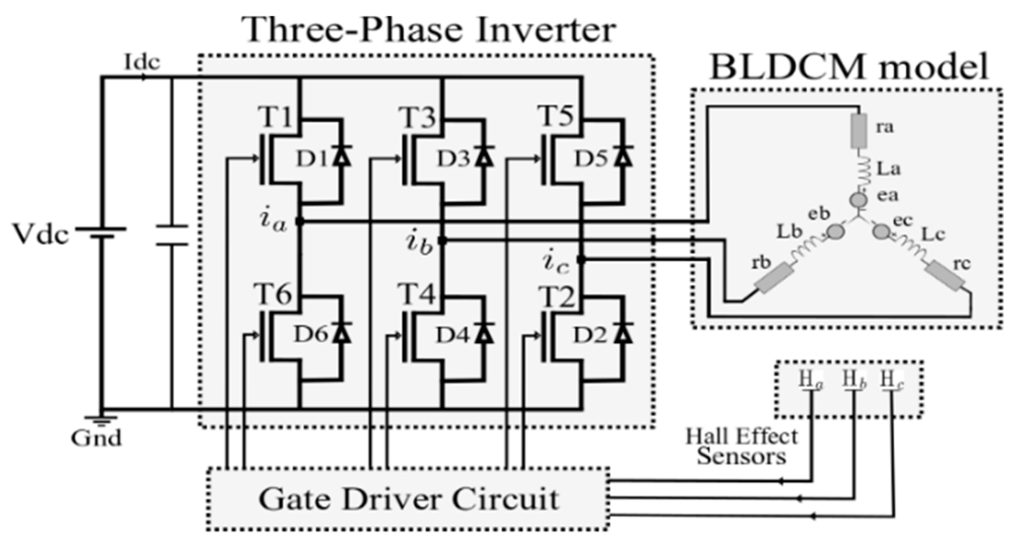
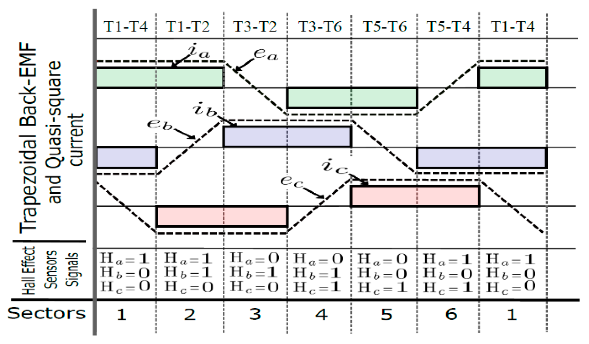
The BLDCM is a synchronous motor with a three-phase winding stator and a permanent magnet rotor. Two motor phases are simultaneously conducting, which means that the gate drive signals are applied to two of the inverters’ MOSFETs at the same time. Knowing which MOSFETs must be conducting is determined using Hall effect sensor signals denoted by Ha, Hb, and Hc. These signal combinations give an image of the rotor position.
Different simulation models of the BLDCM were proposed in References [
24,
25,
26,
27]. Some authors presented a global modeling using inverter mathematical equations [
28], whereas others were based on motor equations [
29,
30].
The BLDCM phase can be modeled as a resistance in series with an inductor and a back-EMF, as shown in
Figure 1.
Figure 2 depicts the phase current waveforms, Hall effect sensor combinations (numbered as sectors), and the inverters’ conducting MOSFETs.
The model equations of the BLDC motor are presented as follows [
24,
25,
26,
27,
28,
29,
30]:
where
, and
are the stator winding phase voltages;
and
are the stator winding resistances;
and
are the phase inductances;
and
are the phase currents; and
and
are the back-EMFs.
The electromagnetic torque and the motor motion are given respectively by Equations (2) and (3):
where
is the rotor angular velocity,
is the viscous friction coefficient,
is the moment of inertia, and
is the load torque.
In
Figure 2, the transition from sector 2 to sector 3 induced an electromagnetic torque expressed by the following Equation (4) [
11,
14]:
where
E is the flap-top value of the back-EMF.
Based on Equation (4), it could be understood that the electromagnetic torque was proportional to the noncommutated phase current during the commutation period. However, in practice, current shapes are not like those presented in
Figure 2. There is a “dead time” between each commutation from one sector to another. This is due to the difference between the MOSFET rise and fall times. More details about such differences can be found in Reference [
10].
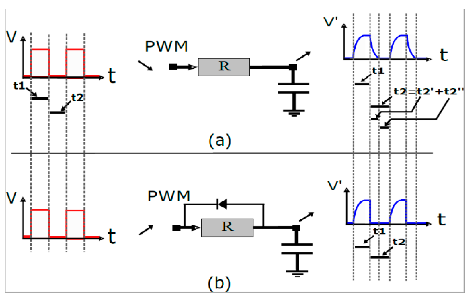
3. Analysis of R-C Filter Implementation
Depending on the MOSFET features, the current flow from the drain to the source depends on the gate voltage .
For the BLDCM, the PWM mode is generally preferred for speed variation where the duty ratio is an image of an analogue signal. Using digital-to-analogue conversions, the duty ratio is calculated, and the appropriate PWM signal is delivered to the MOSFET gate to control the input voltage , which refers also to input current control.
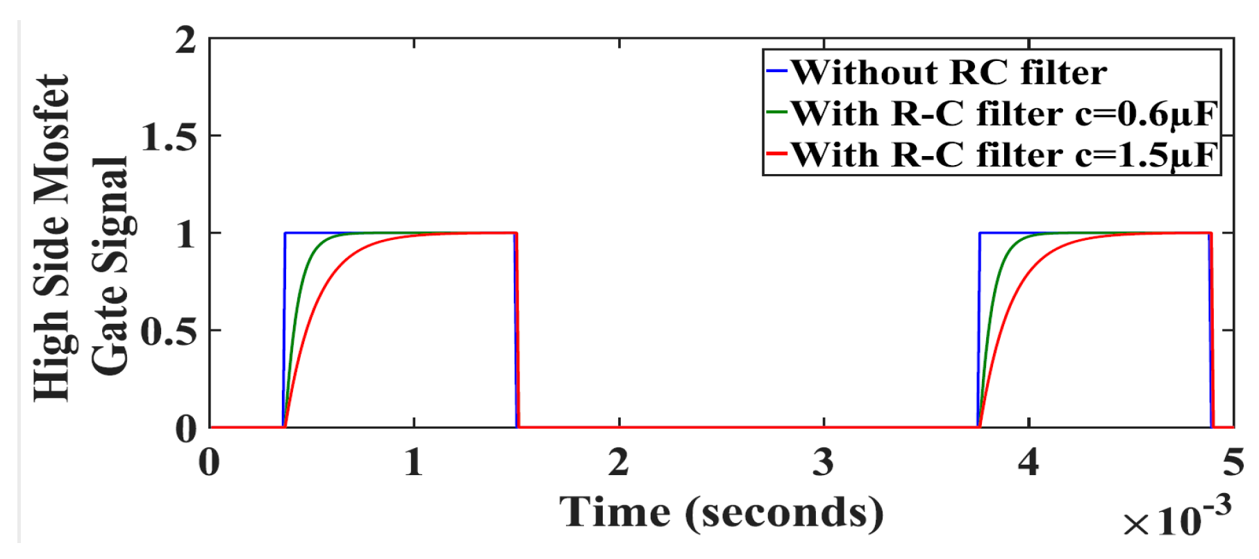
The PWM signal is a succession of discrete states for well-chosen times. In the proposed control method, the discrete states transitions were avoided by adding an R-C filter between the PWM generator and the gate of the MOSFETs, which allowed smooth transients in the changing parts. This changing mode is explained in
Figure 3a.
The encountered problem in this mode of control was the delay time added in the passage portions toward zero (
). For the normal BLDCM control, this time equaled the fall MOSFET’s time that can be achieved by adding a diode in parallel with the resistance, as shown in
Figure 3b. The diode allowed the ability to discharge the capacitor quickly through the creation of a connection with the ground delivered by the PWM block.
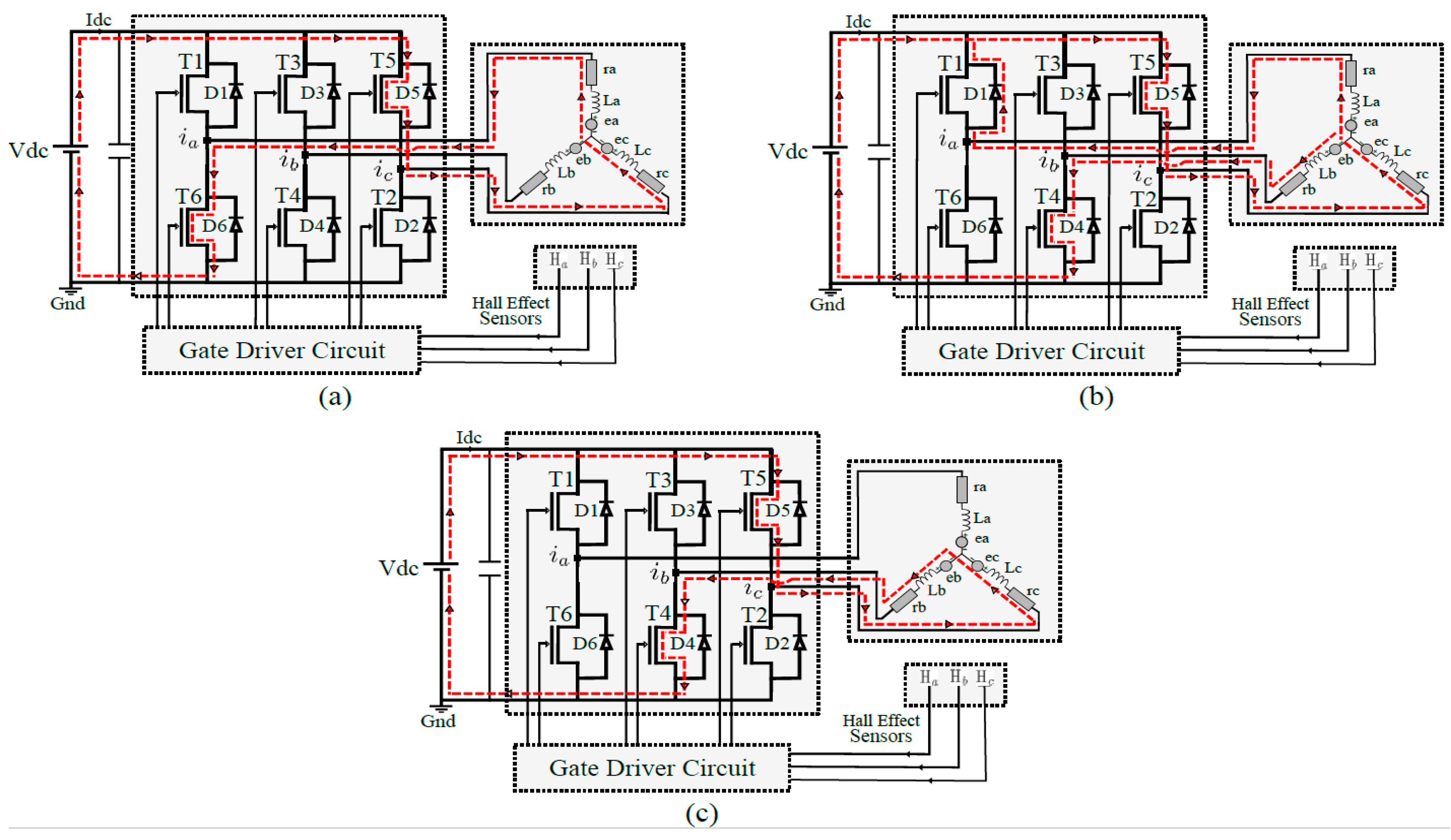
In order to present the detailed impacts of the proposed control method on the motor performance, two current commutation cases must be distinguished, the upper-bridge current commutation and the lower-bridge current commutation. Detailed equations with the equivalent inverter schematic in both cases are presented as follows.
3.1. Lower-Bridge Current Commutation
At the lower-bridge current commutation, the analysis was done when switching off the MOSFET
and switching on the MOSFET
.
Figure 4 shows the MOSFET states before, during, and after the commutation interval for this case. A 100% duty ratio was chosen for simplification purposes.
The voltage equations can be written as:
In this case,
and
[
30].
The motor phase currents were calculated and are presented as follows:
Using Equation (11), the inverse Laplace transform, and the initial value of the phase currents
and
, the resulting phase currents equations are expressed as Equations (12)–(14):
In this case, when using the R-C filter, the equations of the motor phase currents remained the same.
3.2. Upper-Bridge Current Commutation
During the upper-bridge current commutation, the analysis was done when switching off the MOSFET
and switching on the MOSFET
.
Figure 5 presents the MOSFET states before, during, and after the commutation interval for the upper-bridge current commutation.
The voltage equations can be written as:
In this case,
and
[
30]. The motor phase currents are:
Using the inverse Laplace transform and the initial value of the phase currents,
and
, the calculated phase currents are expressed as Equations (21)–(23):
The motor phase currents, when using the R-C filter, are:
From the reported equations, the difference between upper-bridge and lower-bridge current commutation cases was observed at the incoming connected terminal voltage: When the lower-bridge commutation was activated, the terminal voltage of the incoming commutated phase (phase b) was equal to zero (connected to the ground). The R-C filter on the gate of the MOSFET
did not present any difference because the incoming commutated phase voltage still equaled zero until the total conduction of the MOSFET
. In this case, the outgoing commutated phase was connected to the DC link voltage through the freewheeling diode
, as shown in
Figure 5b, and was not controlled by the gate of the MOSFET
. This means that any difference from the normal controlling mode would not appear when the gate of the lower MOSFET
was commutated using the R-C filter. Unlike the upper-bridge current commutation, the terminal voltage of the incoming commutated phase was the DC link voltage. Controlling the gate of the MOSFET
using the R-C filter was the reason for the impact of this on the absorbed current. This was due to the delay added before the total conduction of the MOSFET
. This fact proved that the R-C filter impact was more important when it was implemented on the upper-bridge gate’s MOSFETs.
It is worth mentioning that the phase currents equations, when adding the R-C filter, had higher values than without using an R-C filter. This can be seen in the additional “exponential” term added from controlling the gate of the MOSFET by the R-C filter (Equations (24)–(26)). It should be also emphasized that the R-C filter frequency should be well-chosen. It must be higher than the PWM control signal frequency to allow the motor to work without disturbances.
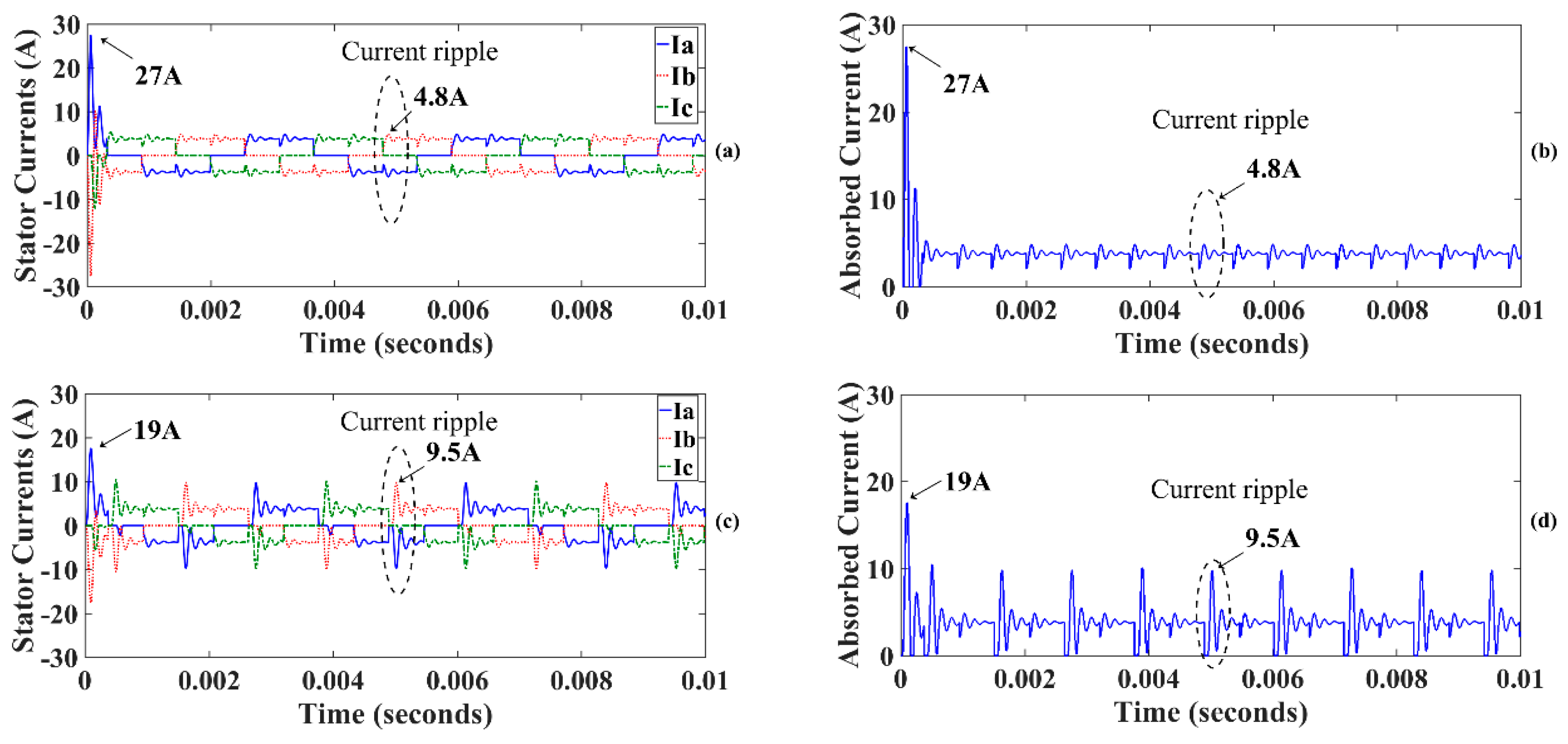
4. Simulation and Experiment Results
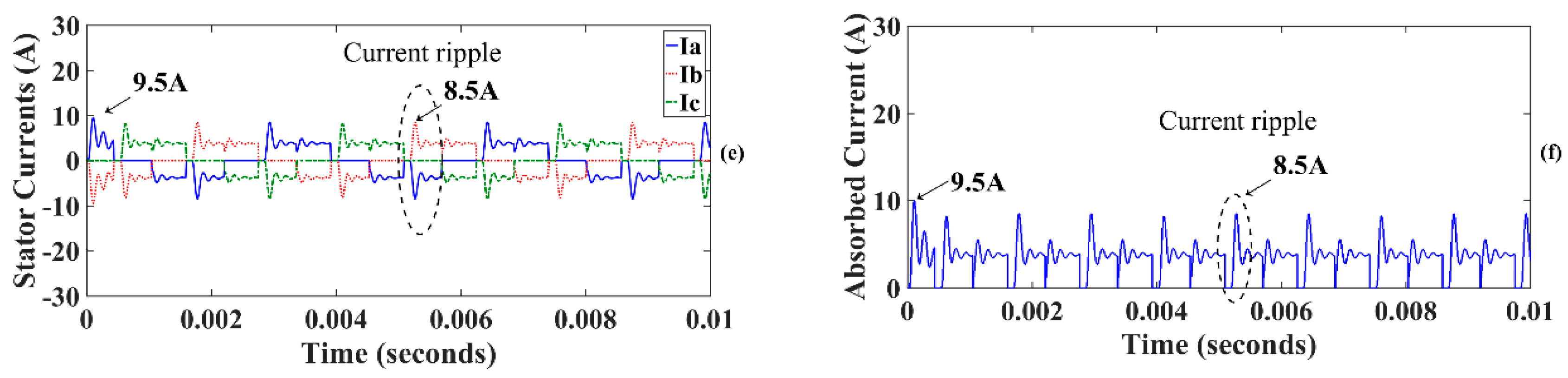
Based on the obtained results, one can see that the current spike in the start-up phase without using the R-C filter (27 A) (
Figure 6a) had a higher value than the one absorbed when using the R-C filter (19 A) (
Figure 6c). This reduction in current spike value was obtained with an R-C filter frequency of 2.6 kHz. Changing the latter to 1 kHz, the current spike was reduced to 9.5 A (
Figure 6e). Despite these decreases in current spikes, more current ripples appeared. The noncommutated phase induced a higher current ripple value during the commutation period in a steady state. Compared to the normal control strategy that induced 4.8 A, a 2.6 kHz R-C filter frequency induced a 9.5 A current ripple value, whereas the use of a 1 kHz R-C filter frequency decreased this current ripple to 8.5 A. The obtained results were in accordance with those of the absorbed current shown in
Figure 6b,d,f. This confirms the obtained analytical results presented in the previous section, in terms of a higher current value during the commutation interval, when compared to the normal BLDCM control.
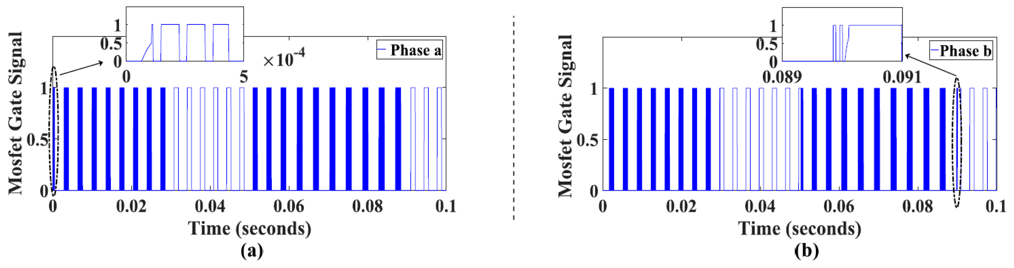
The corresponding MOSFET gate signals are illustrated in
Figure 7 without using the R-C filter and when implementing the latter with a capacitor value of 0.6 µF and 1.5 µF. The difference is illustrated in the delay time added before the total MOSFET conduction. This R-C filter effect was applied only during front edges. During failing edges, the same signal waveform was applied for normal and R-C filter control methods.
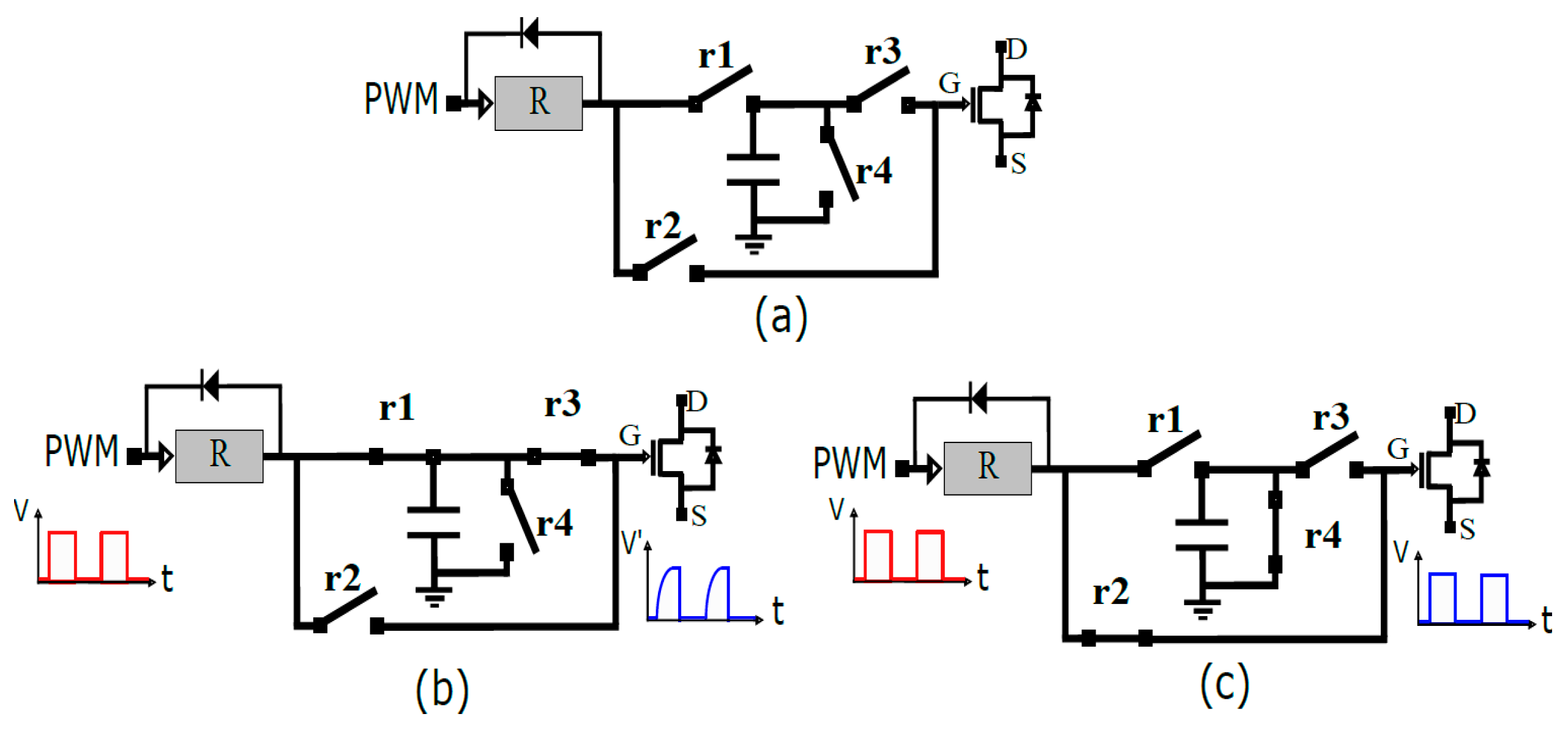
In order to avoid the higher steady state current ripples caused by R-C filter usage, a combination of the two controlling modes, with and without R-C filter, was used. A relays-based selection circuit that allowed for activating or canceling the connection between the PWM block and the R-C filter was utilized. It must be taken into consideration that the proposed schematic must be able to discharge the R-C filter capacitor in nonconduction phases to allow reactivation of the R-C filter effect when renewing. The global schematic is presented in
Figure 8.
Relays r1 and r3 were controlled by the same signal, which was the complement to that which ordered the relays r2 and r4. When the relays r1 and r3 were in conduction, the R-C filter effect was activated and connected to the gate of the MOSFET. During the R-C filter deactivation, relays r2 and r4 were in conduction. This combination connected the PWM signal, after the resistance, directly to the gate of the MOSFET and allowed the capacity to discharge by connecting it to the ground.
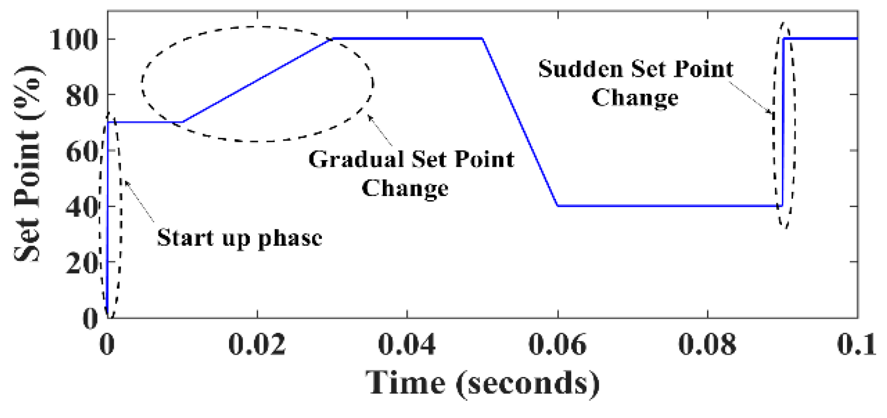
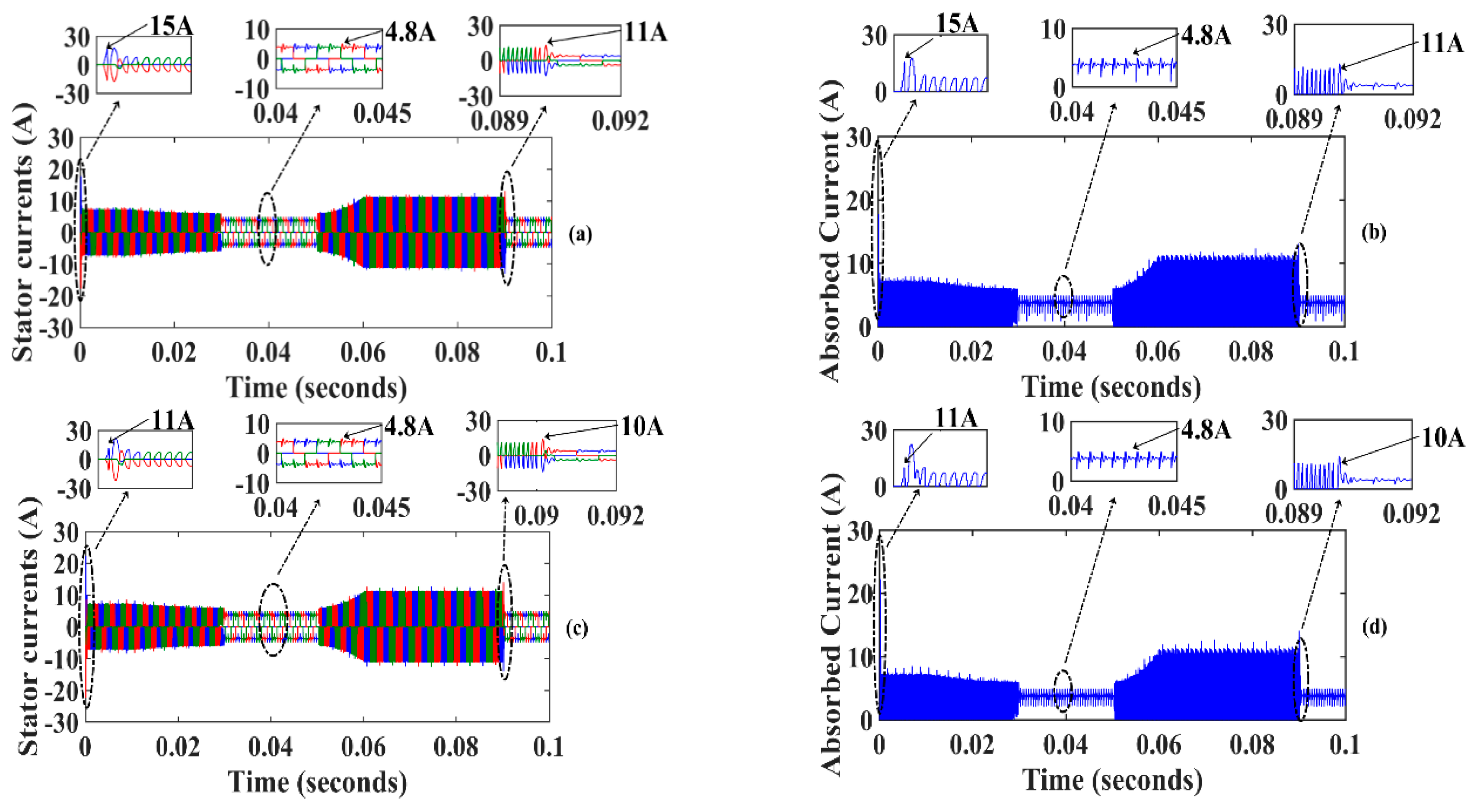
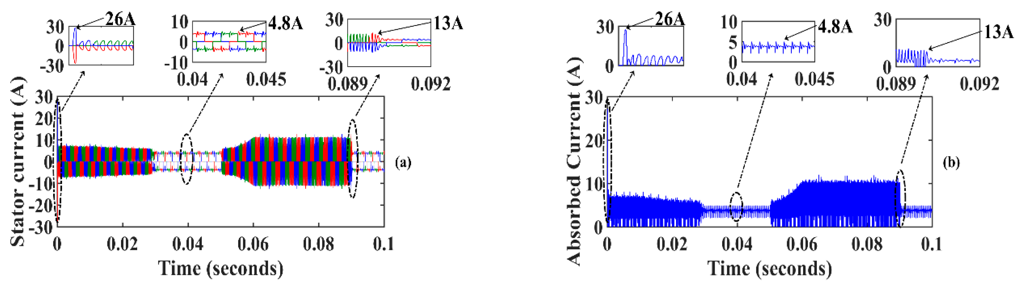
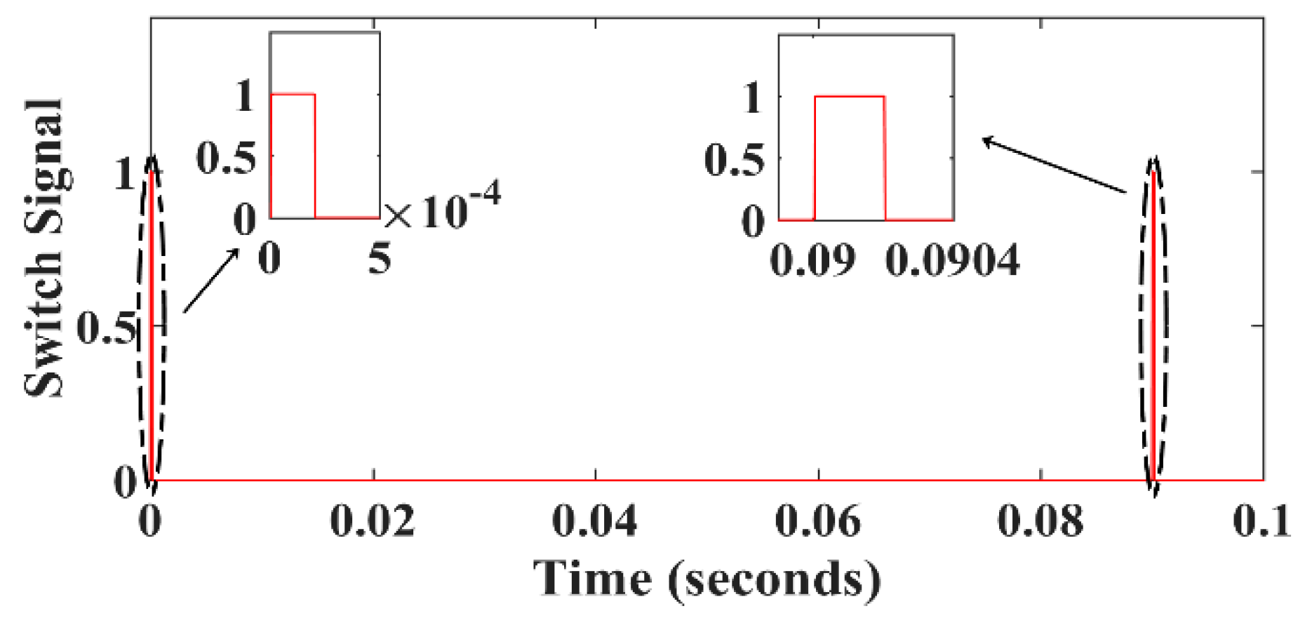
What followed was the activation of the R-C filter in the starting and sudden set point changes. This is explained by what this control method could cause in permanent regimes in terms of current ripple. Sudden changes in the set point were detected by the derivative of the latter and the comparison of it to a certain limit that must not be exceeded, after which the engine would see a significant current spike. Simulation results, using the programmed set point changes profile shown in
Figure 9, are illustrated in
Figure 10 without using an R-C filter and in
Figure 11 with combined “with and without an R-C filter” controls.
Figure 12 depicts the gate voltage signal of the R-C filter-controlled MOSFETs. The chosen set point variations, representing the PWM control signal duty ratio, were utilized to test the activation and deactivation of the R-C filter effect. The related simulation signal is presented in
Figure 13.
From the reported results, without using an R-C filter control, the peak values of the phase current, and thus the input current, reached 26 A during the start-up phase and 13 A during sudden set point change, as illustrated in
Figure 10a,b. However, when implementing the R-C filter with a 0.6 µF capacitor, the current values were reduced to reach 15 A and 11 A during the start-up and sudden set point change, respectively (
Figure 11a,b). After changing the capacitor to 1.5 µF, the start-up and sudden set point changes currents were reduced to 11 A and 10 A, respectively (
Figure 11c,d).
During gradual set point change, the current waveform did not show any spike, which did not necessitate R-C filter effect activation.
From these results, using relays on the six MOSFETs of the inverter seemed to be a satisfactory way to eliminate current ripples in the permanent regimes. The previous calculations, which explained that the R-C filter impact was important when the latter was implemented on the upper-bridge MOSFETs, may have reduced the number of relays and R-C filters from six to three.
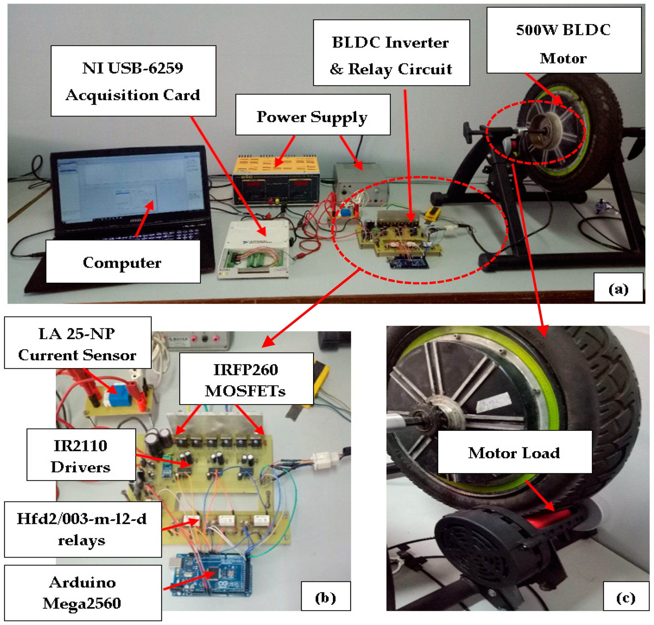
The effectiveness of the proposed method was experimentally proven using the laboratory test rig illustrated in
Figure 14. It was made up of an outrunner BLDCM structure with a neodymium magnet rotor, an inverter composed of IRFP260 MOSFETs, IR2110 gate drivers, a potentiometer, and an Arduino Mega2560 board used to generate BLDCM PWM control signals. The relays-based circuit contained three hfd2/003-m-l2-d relays, in addition to the basic components needed for their control (e.g., transistors, diodes). Based on the potentiometer value and Hall effect sensor signals, PWM control signals were provided to the IR2110 gate drivers through the proposed RC-filters and relays-based circuits for the high-bridge-controlled MOSFETs, and directly from the Arduino to the lower-bridge MOSFETs drivers. The potentiometer derivative was calculated and used for R-C filter activation or deactivation as illustrated previously in
Figure 8. The IR2110 drivers were chosen due to their capability of isolating the high-power side from the low-power side, which ensured programming and interfacing cards security. The PWM frequency was set to 32 kHz, and a National Instrument card, NI USB-6259, was used to acquire input current waveforms with and without using an R-C filter through an LA 25-NP current sensor.
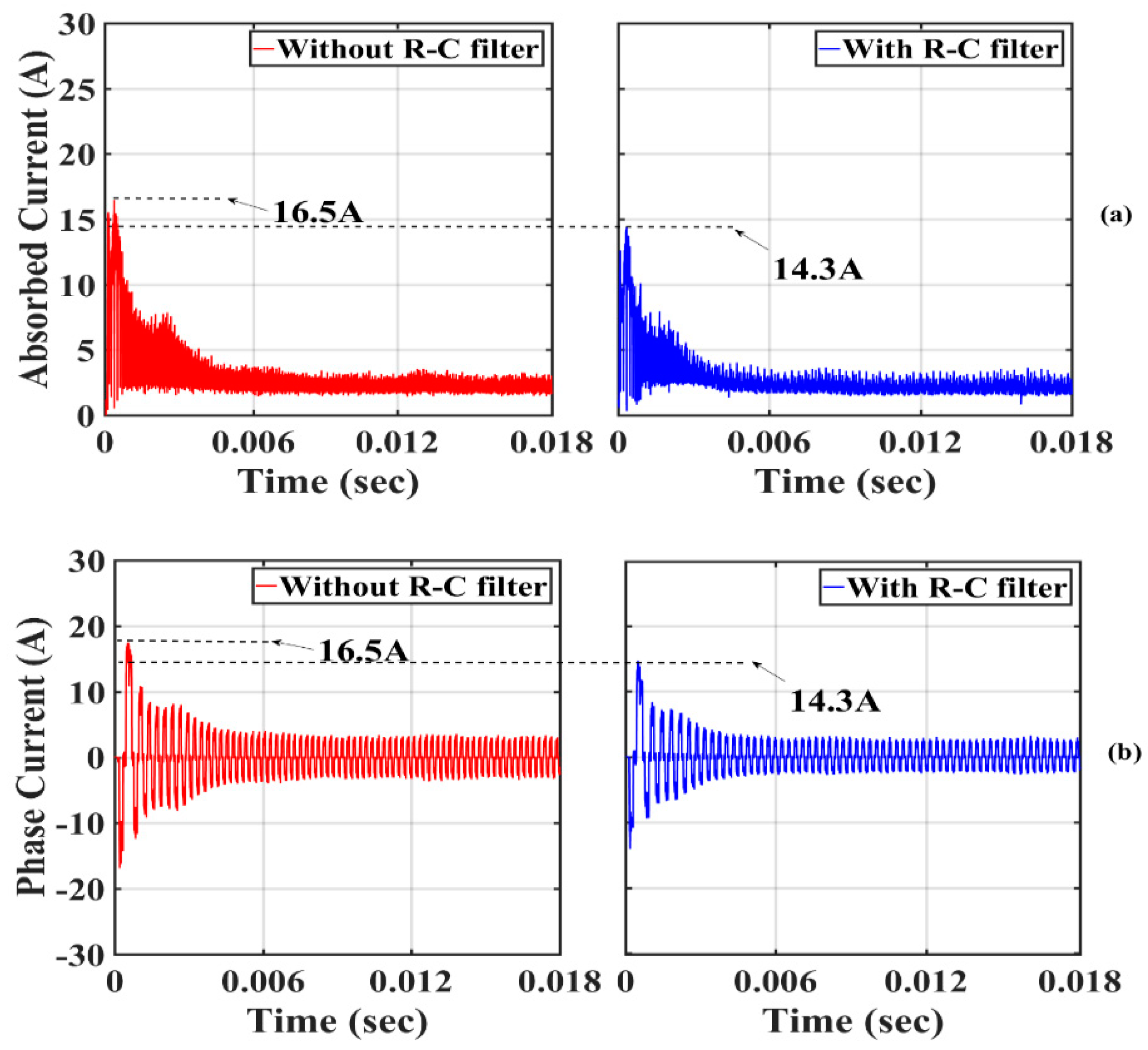
Figure 15 illustrates the experimental results with and without using an R-C filter during the start-up phase. It can be noticed that current spikes in normal BLDCM control (using the discrete PWM signal only) reached 16.5 A. In contrast, with the proposed method, the absorbed current spikes decreased to 14.3 A due to the induced delay in the MOSFET command before reaching the threshold voltage. These results confirm those illustrated through the first dashed line ellipsis in
Figure 11a–d in terms of current spike reduction. It should be mentioned that the experimental results were obtained using a 15 kHz R-C filter frequency, which explains the current spike values difference from those in the simulation. In permanent regimes, the current waveforms are the same for both cases (with and without an R-C filter). The 15 kHz R-C filter frequency was selected to cope with some test rig limitations (such as program execution frequency and acquisition memory saturation), which were also the reason for presenting only start-up phase results. Improving the test rig performance should result in more of a decrease in the current spikes.
As a conclusion, one can see that these experimental results support the simulation and analytical analyses and also prove the effectiveness of the proposed current spikes minimization method.
5. Conclusions and Future Work
In this paper, BLDCM current spike limitations during start-up and set point sudden changes were presented by modifying the MOSFET gate control signals. An R-C filter was placed between the PWM signal generator and the MOSFET gate in order to smooth the discrete PWM control signal during transition phases. The proposed method induced more current ripples in the permanent regimes, which imposed a combination of the use of the R-C filter or not. This was achieved using relays-based circuits to activate and deactivate the R-C filter effect. Simulation results were carried out and showed that the proposed method attenuated the current spikes amplitude in both the start-up and sudden set point changes by 40% and 35%, respectively. An experimental test rig was designed to approve such results. In fact, the experimental results showed a decrease in current spikes amplitude during the start-up phase, with a percentage of 13%. This approach is appreciated since it did not require a high power supply and did not cause energy interruptions when using a limited current power supply.
It should be noted that the limitation of the proposed method, apart from higher current ripples during steady states, was the R-C filter frequency, which had to be well-chosen for adequate motor operation. Moreover, relays-based circuits had to be fast enough to respond when current spikes were detected. This fact can be addressed in further works by the use of high-speed switch-based circuits to control R-C filter activation and deactivation, such as MOSFETs. Additionally, basic and in-depth studies concerning the motor and converter efficiency, with and without an R-C filter, will be explored.


