Symmetrical Loss of Excitation Fault Diagnosis in an Asynchronized High-Voltage Generator


Abstract
:1. Introduction
2. The Loss of Excitation Simulation Model for the Asynchronized High-Voltage Generator
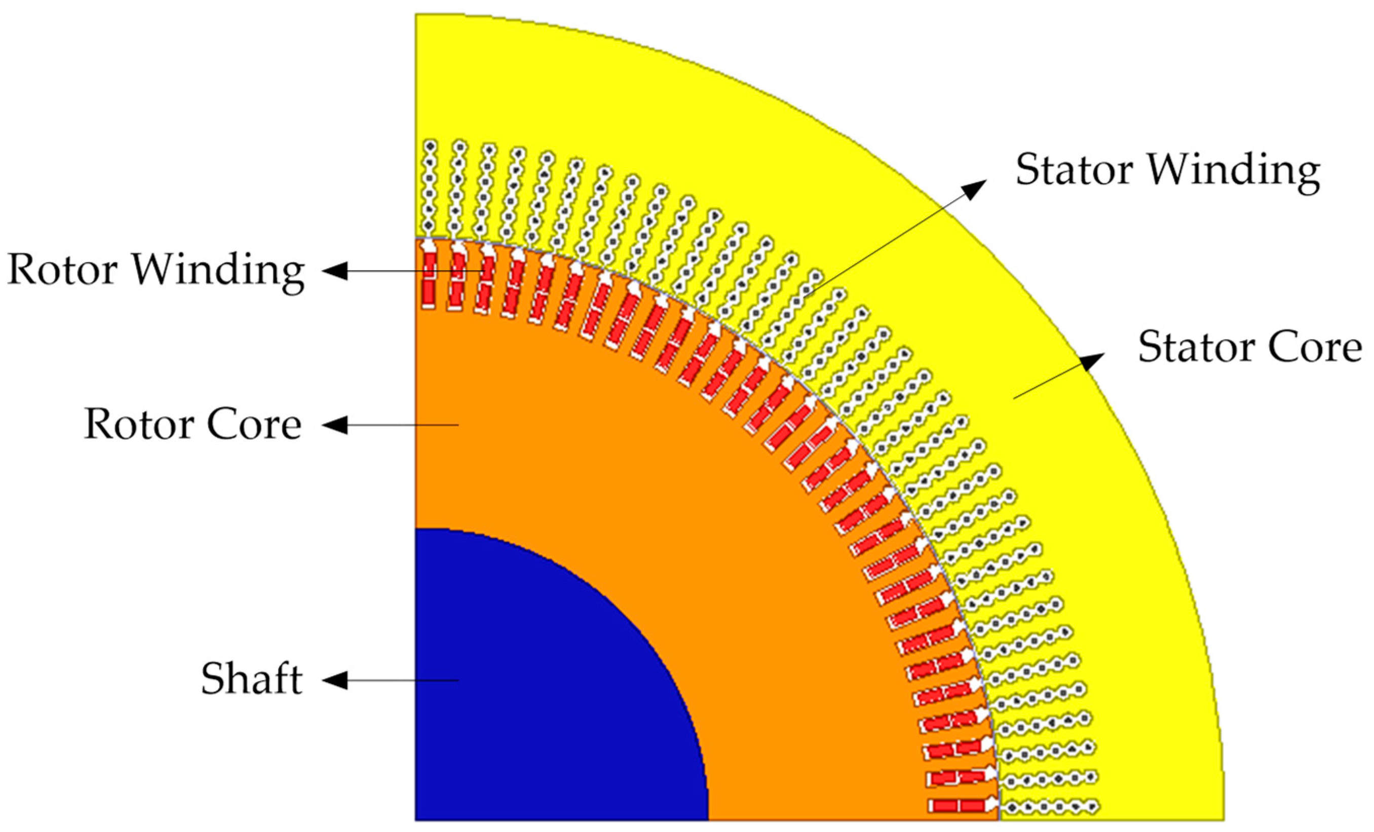
2.1. Finite Element Model
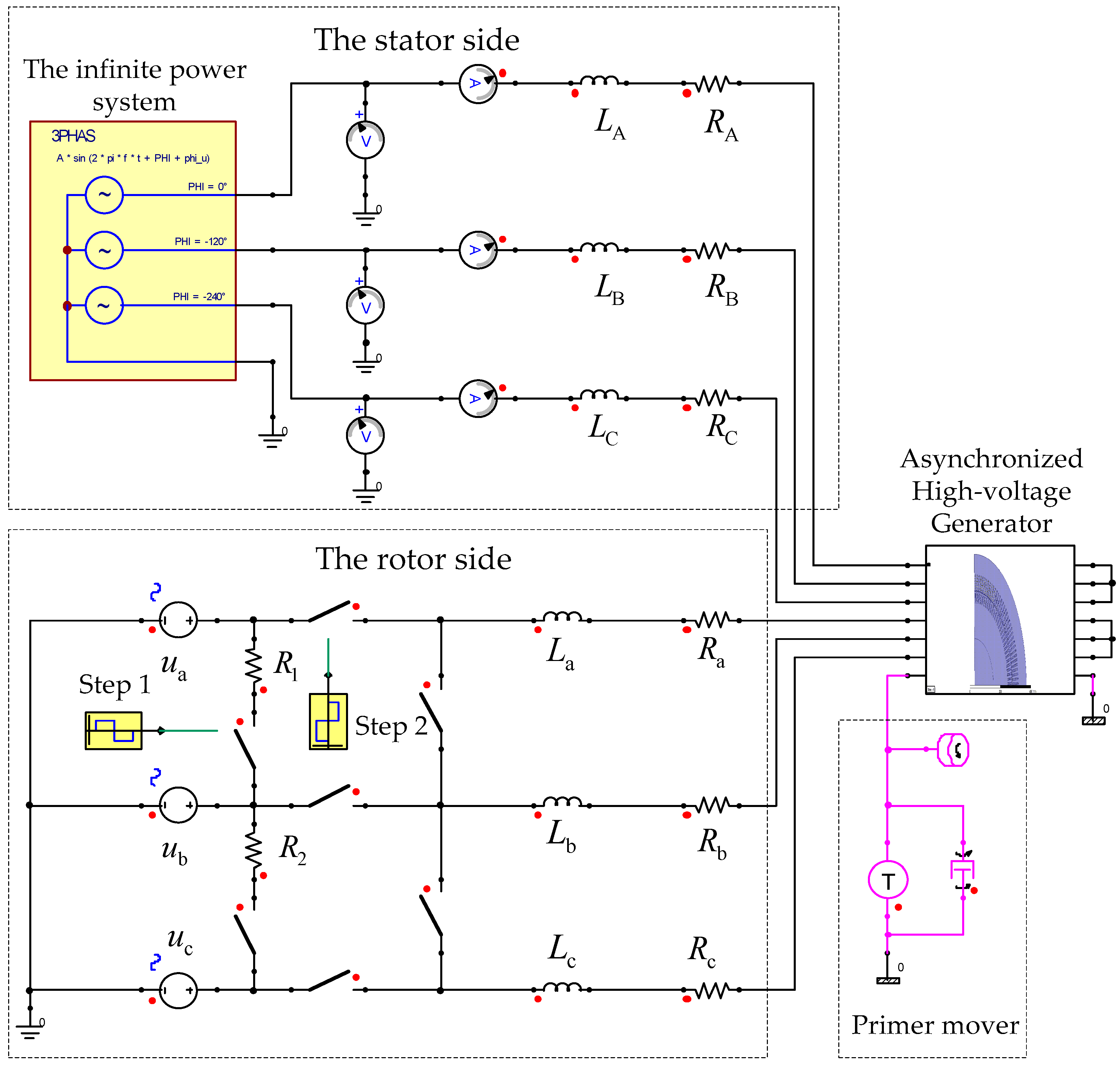
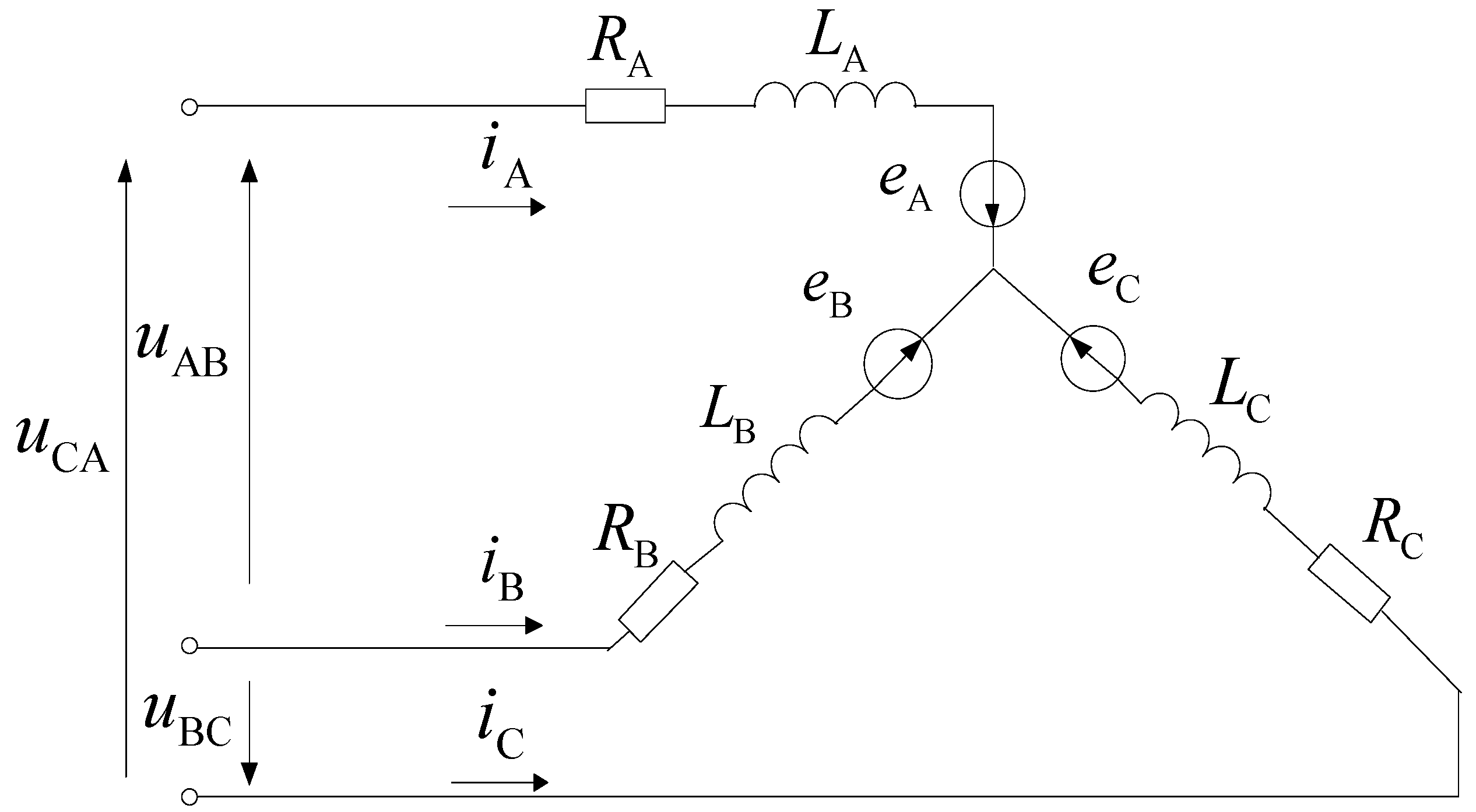
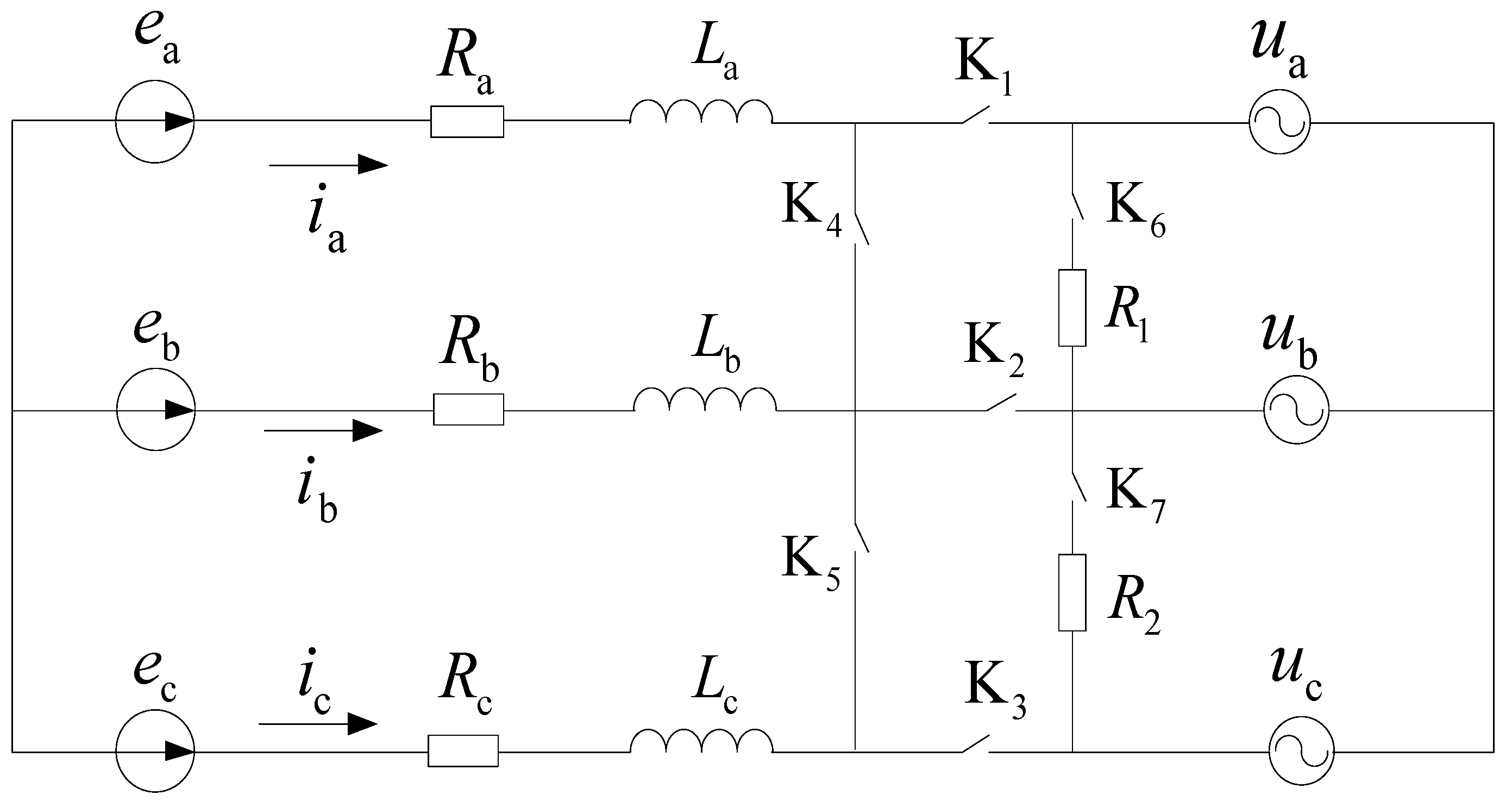
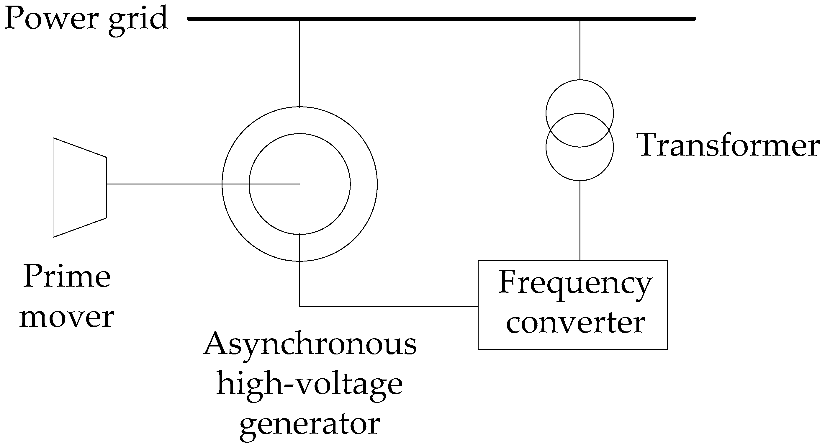
2.2. External Circuit Model
2.3. The Field-Circuit-Movement Coupling Simulation Model
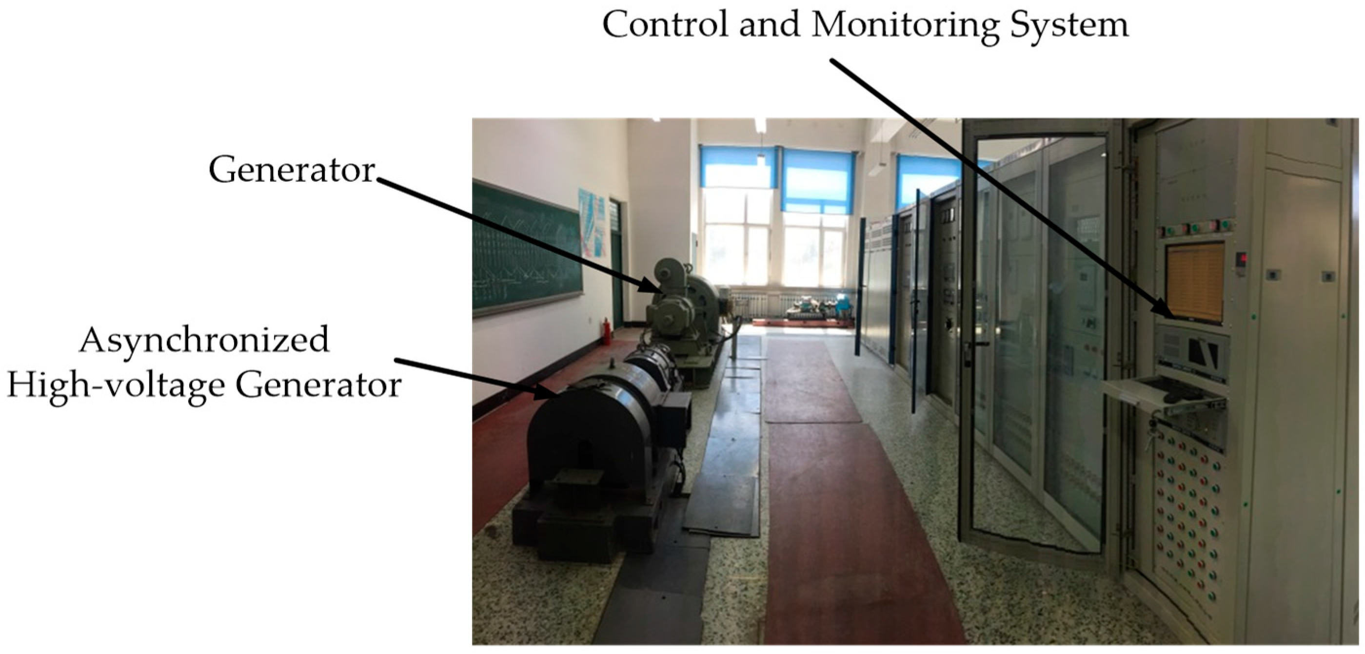
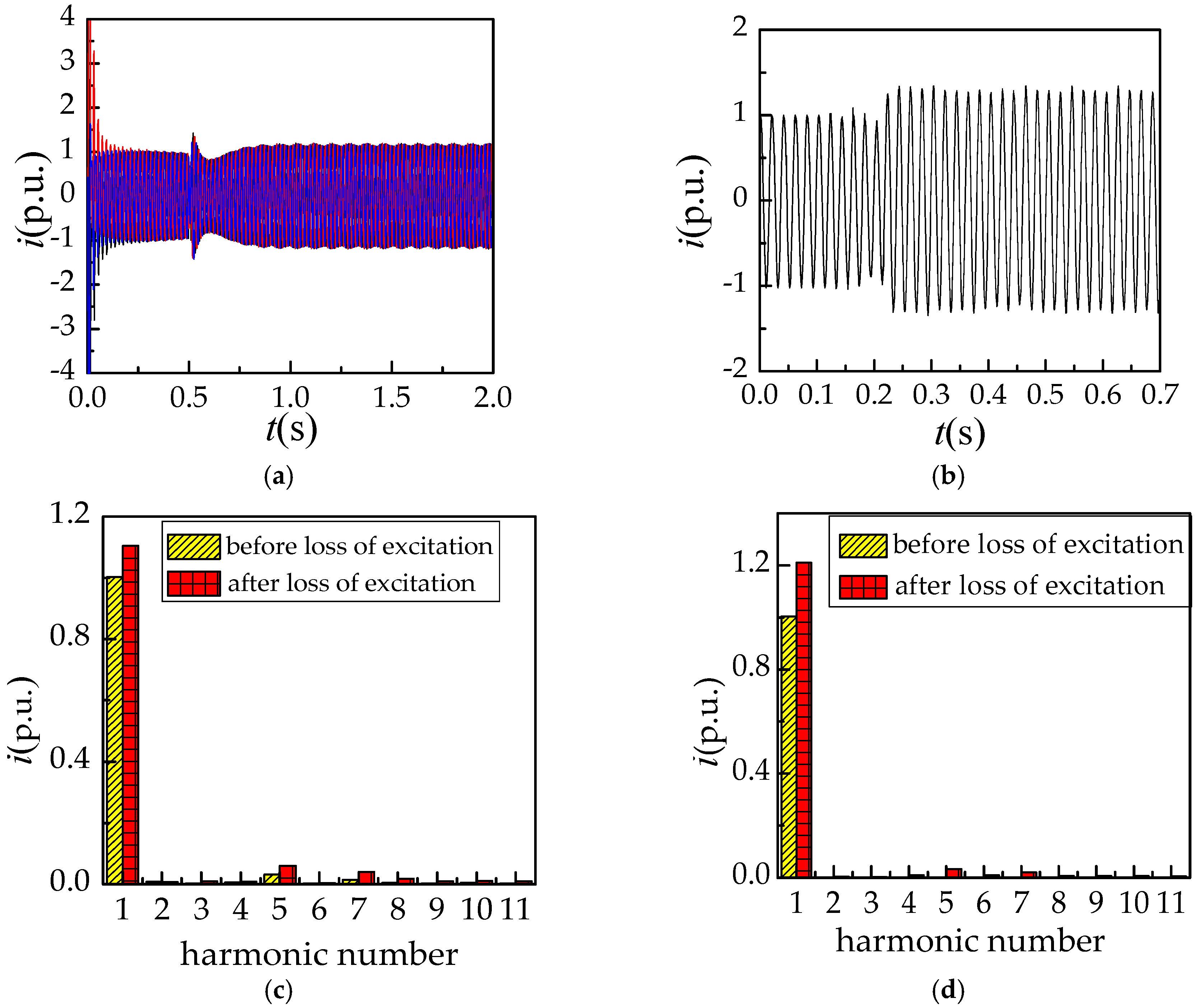
2.4. Model Verification
3. Analysis of Simulation Results for the Asynchronized High-Voltage Generator
3.1. Analysis of Symmetrical Loss of Excitation Simulation Results
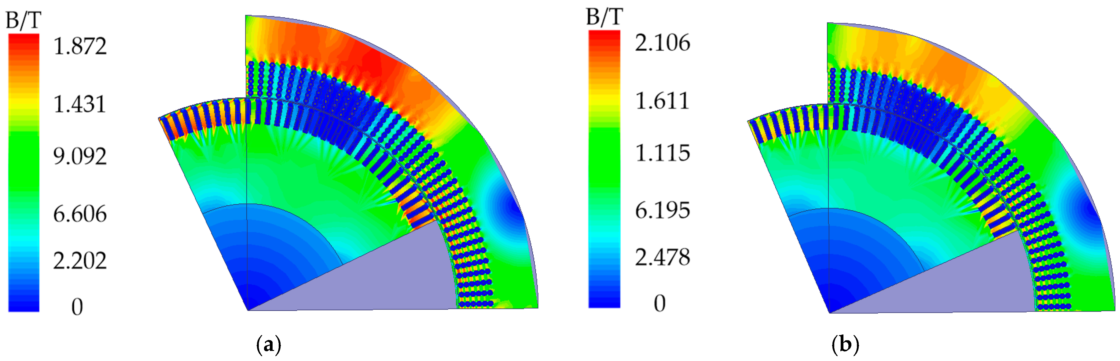
3.1.1. Analysis of Magnetic Field under the Three Phase Short-Circuit Loss of Excitation
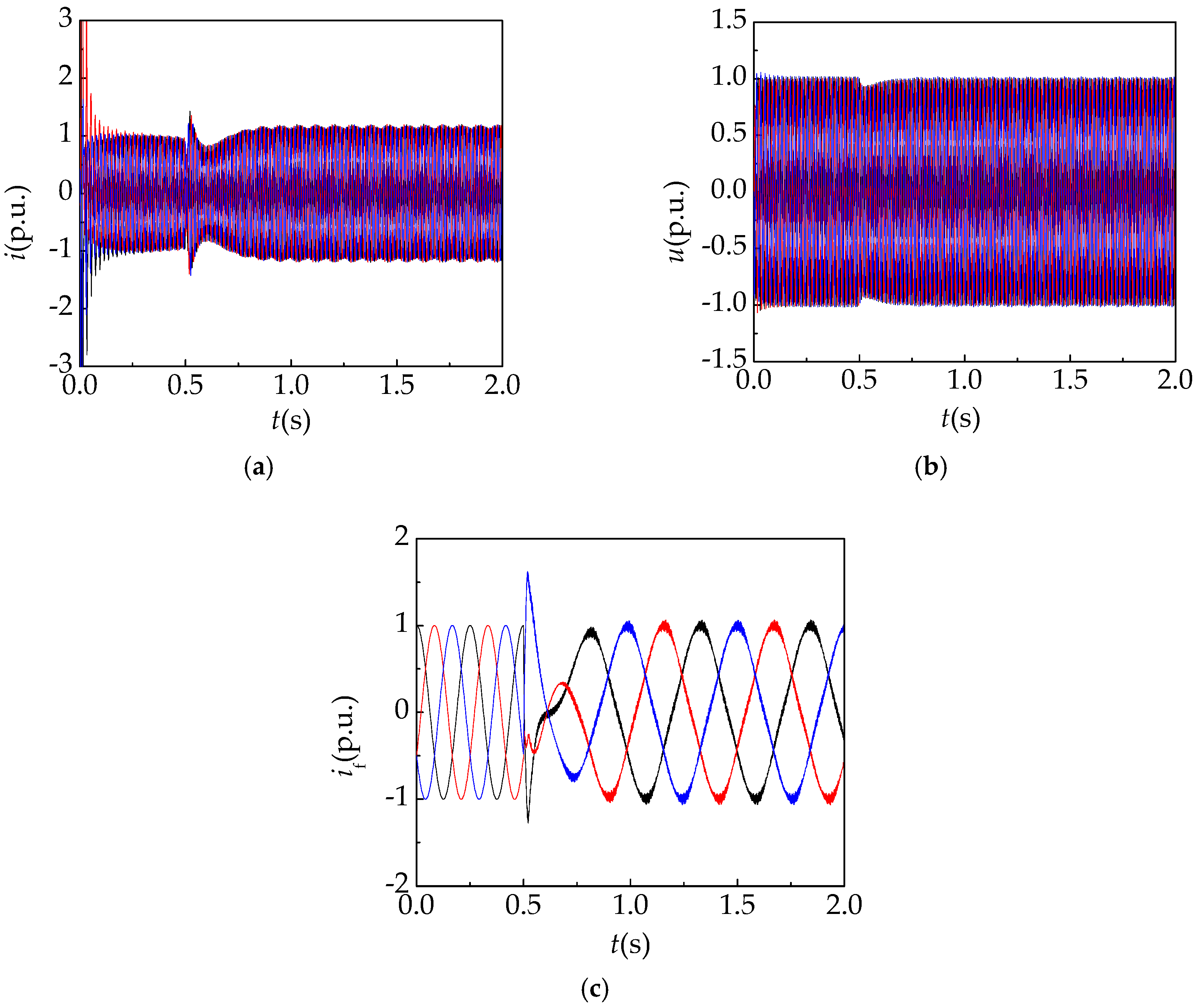
3.1.2. Analysis of Electrical Quantities under Three Phase Short-Circuit Loss of Excitation
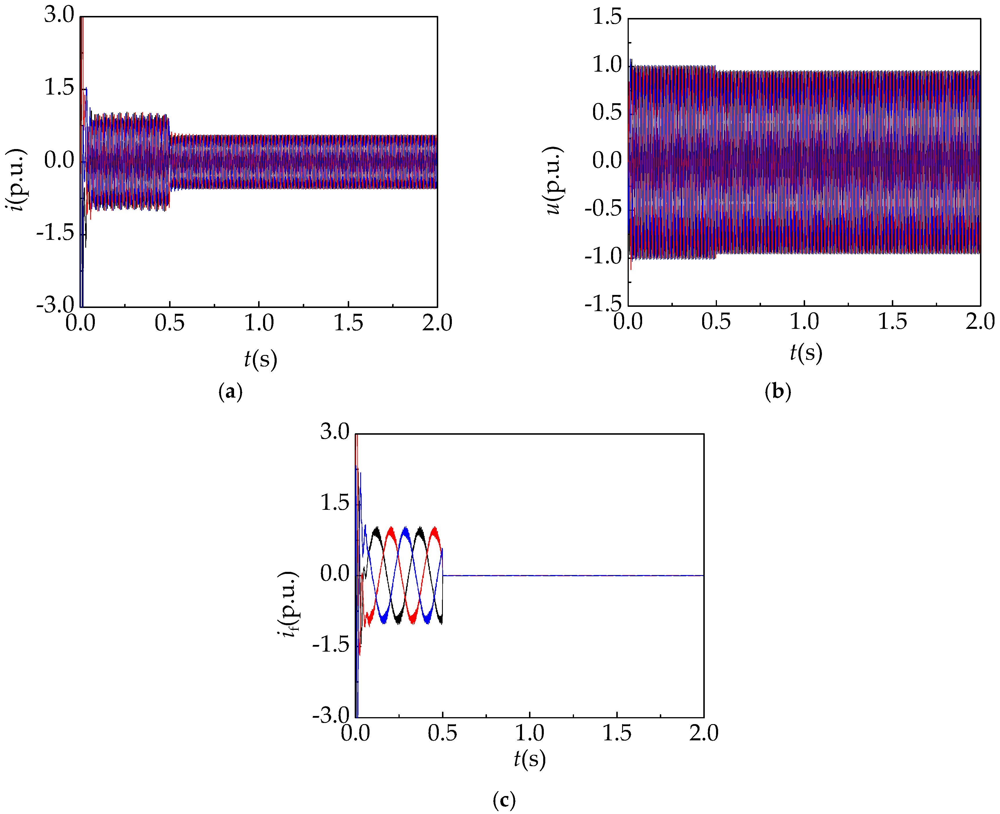
3.1.3. Analysis of Loss of Excitation Electrical Quantities under Three Phase Open-Circuit
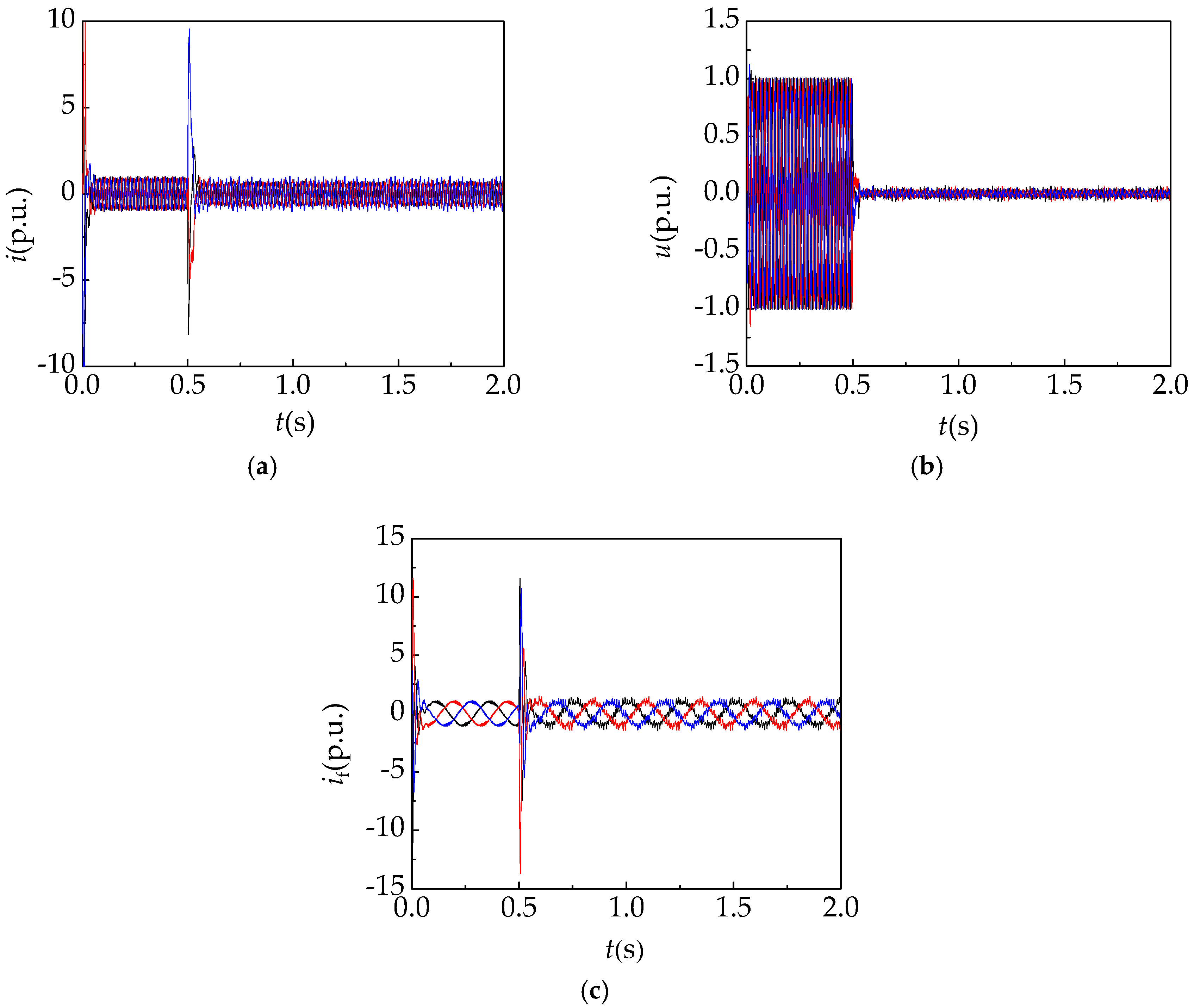
3.2. Analysis of the Three Phase Short-Circuit Fault on the Stator Side Simulation Results
4. Symmetrical Loss of Excitation Fault Diagnosis System Based on Wavelet Packet and BP Neural Network
4.1. The Composition of the Fault Diagnosis System
- (1)
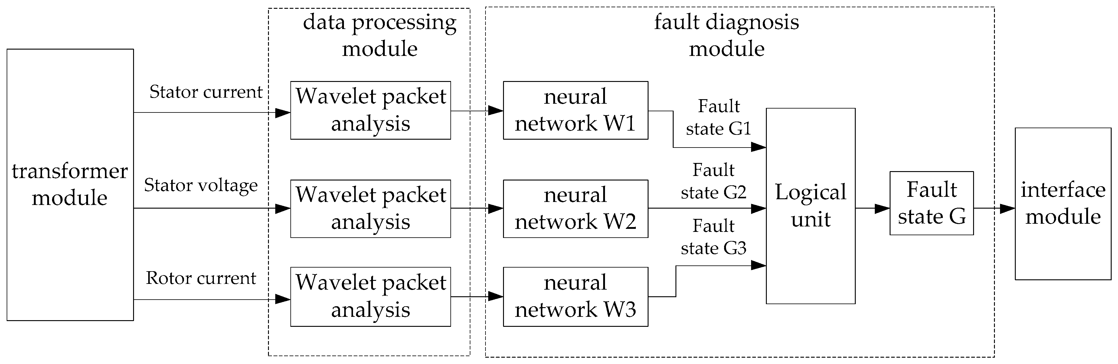
- The transformer module is applied to acquire the stator current signal, stator voltage signal, and rotor current signal of the asynchronized high-voltage generator. The collected signals include: The signal when the generator is in the normal operation state, the signal when the generator is under the three phase short-circuit loss of excitation fault, the signal when the generator is under the three phase open-circuit loss of excitation fault, and the signal when the generator is under the three phase short-circuit fault on the stator side.
- (2)
- The outputs of the transformer module act as the inputs to the data processing module. The data processing module applies the wavelet packet analysis method to obtain the energy eigenvector of each frequency band for the rotor voltage signal, the stator voltage signal, and the stator current signal.
- (3)
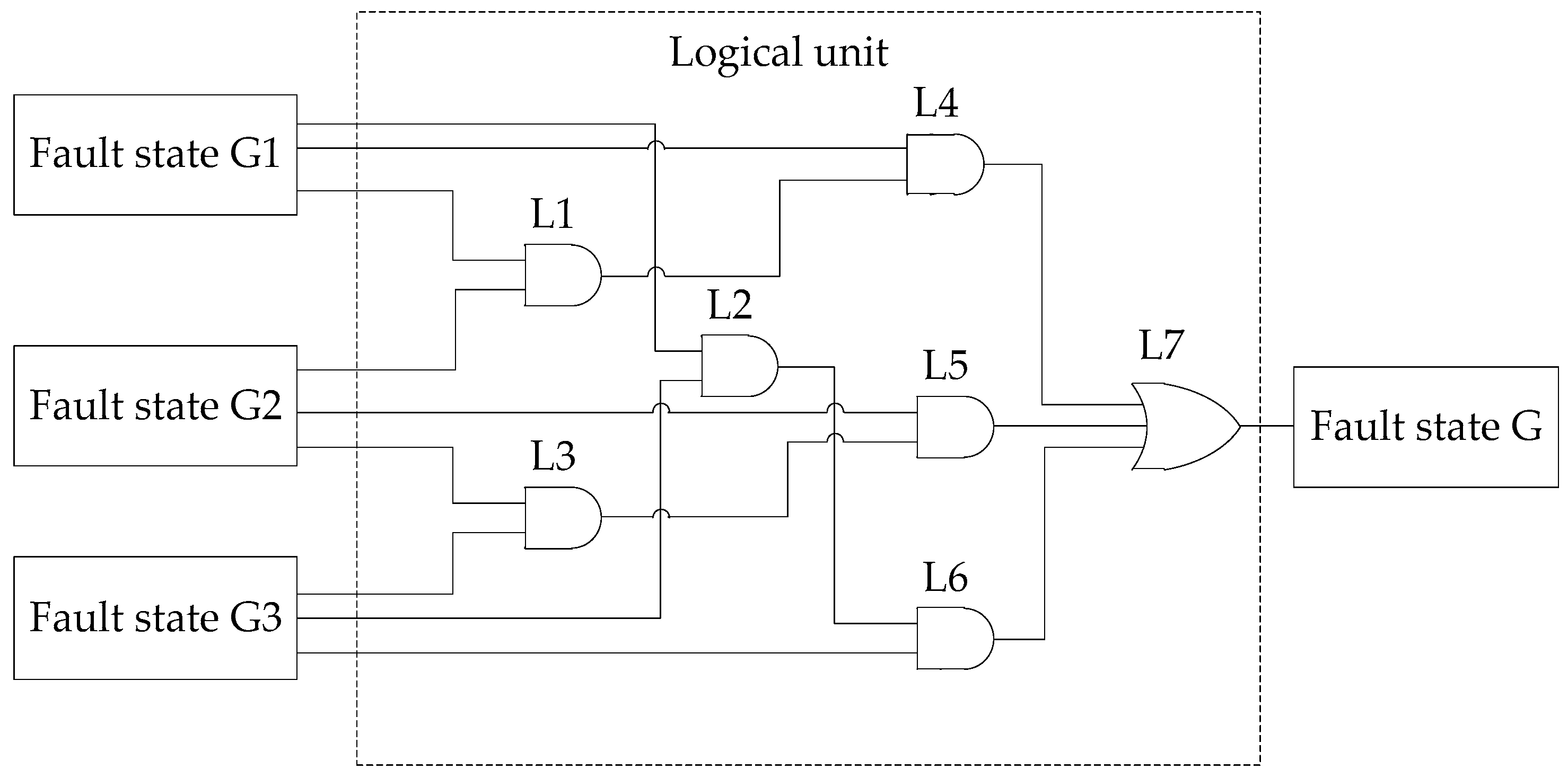
- The outputs of the data processing module act as the inputs to the fault diagnosis module. The fault diagnosis module comprises a neural network, W1; a neural network, W2; a neural network, W3; and a logical operation unit. Firstly, the energy eigenvector of the stator current signal extracted by the wavelet packet analysis is used as an input vector of the neural network, W1. Then, we obtain the fault state, G1, through neural network training. Similarly, we obtain the fault state, G2, and fault state, G3, through the stator voltage and rotor current signal, respectively. Last, the fault states, G1, G2, and G3, are used as the inputs of the logical unit, which outputs the fault state, G.
- (4)
- The interface module is configured to display the fault state obtained by the fault diagnosis module.
4.2. The Wavelet Packet Analysis
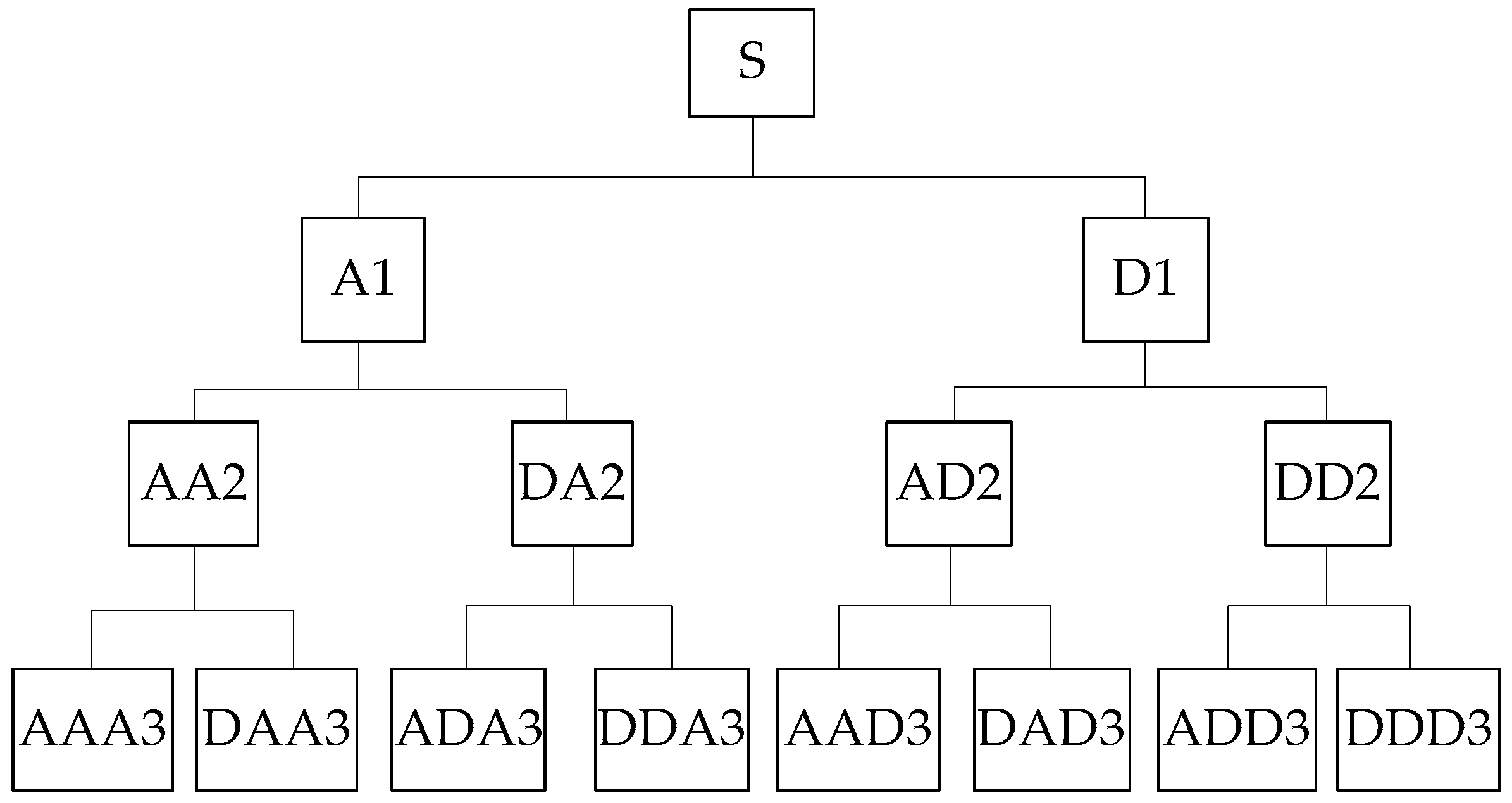
- The fourth-order wavelet of the Daubenchies wavelet series is used to perform three-layer wavelet packet decomposition on the sample signal, which have good localization in both time and frequency domains. The decomposition structure is shown in Figure 14. S is the total reconstructed signal, A represents a low frequency, D represents a high frequency, and the serial number at the end represents the number of wavelet packet decomposition layers.
- Reconstruct the decomposition coefficients of wavelet packets in each layer. The decomposition relationship is S = AAA3 + DAA3 + ADA3 + DDA3 + AAD3 + DAD3 + ADD3 + DDD3.
- Suppose the corresponding energy of Si is Ei′. The total energy of each sub-band signal is:In Equation (3): xi,k is the magnitude of the discrete point for the reconstructed signal, Si; i = 0, 1, 2, …, 7; k = 1, 2, …, n; n is the number of the signal sampling points.
- When the energy is high, Ei′ is usually a large number and the calculation will be complicated, so the energy value needs to be normalized, that is:
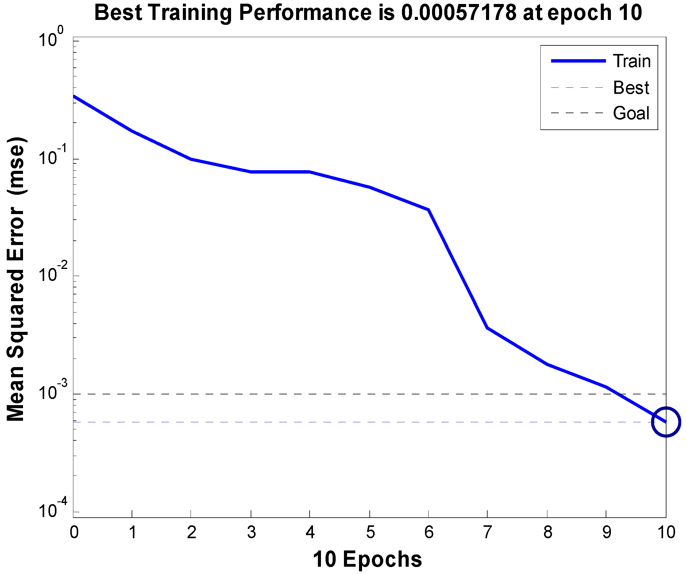
4.3. The BP Neural Network
4.4. The Logical Unit
4.5. Analysis of Fault Diagnosis Results
5. Conclusions
- The field-circuit-movement coupling finite element model is established for the asynchronized high-voltage generator, which is used for simulating three kinds of faults (three phase short-circuit loss of excitation fault, three phase open-circuit loss of excitation fault, and three phase short-circuit fault on the stator side). The analysis result is a basis data for the symmetrical loss of excitation fault diagnosis of asynchronized high-voltage generators.
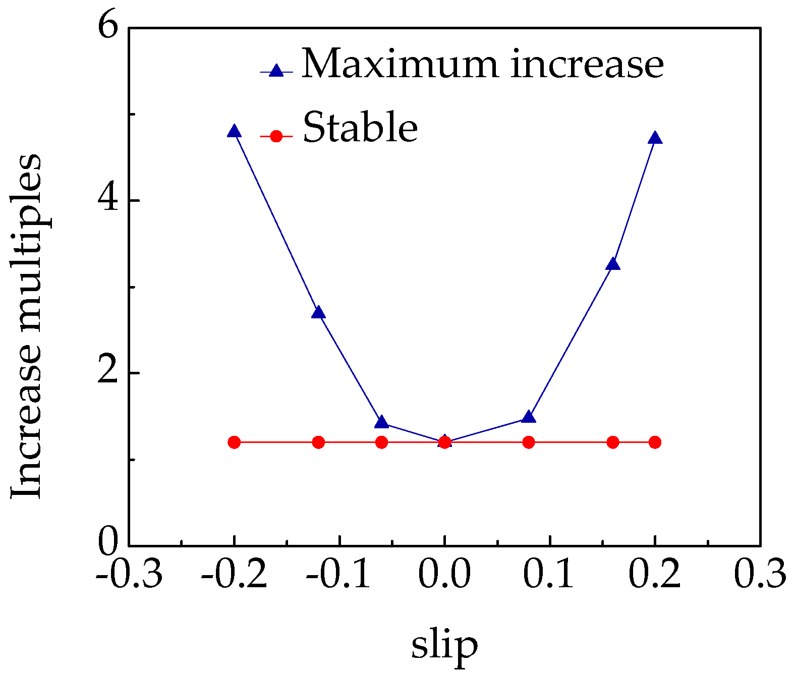
- The stator current maximum increase multiple of the asynchronized high-voltage generator at the moment of loss of excitation is related to the slip rate in the stable operation state before loss of excitation. The maximum stator current will rise with an increase of the slip rate.
- For asynchronized high-voltage generators, the stator current has a sharp increase at the moment of the three phase short-circuit loss of excitation fault and three phase short-circuit fault on the stator side, so it is necessary to adopt an effective fault diagnosis technique to eliminate the interference of the three phase short-circuit fault on the stator side.
- The symmetrical loss of excitation fault diagnosis system is established for the asynchronized high-voltage generator and the logic unit is introduced based on wavelet packet analysis and BP neural network. It can be concluded that this system effectively confirmed the interference of the three phase short-circuit fault on the stator side, accurately diagnosing the type of loss of the excitation fault, and improving the accuracy of fault diagnosis results.
Author Contributions
Funding
Conflicts of Interest
References
- Ge, B.; Zhang, D.; Liang, Y. Powerformer and Its Recent Development. Trans. China Electr. Soc. 2005, 20, 26–30. [Google Scholar] [CrossRef]
- Zhang, H.; Xing, L.; Yan, W. Review on asynchronous generators under synchronous operation mode. North China Electr. Power 2000, 4, 48–50. [Google Scholar] [CrossRef]
- Yan, X.; Yu, S.; Zhu, L.; Li, M. Study of the static stability of asynchronized synchronous generators. Proc. CSEE 2002, 22, 89–93. [Google Scholar] [CrossRef]
- Chowdhury, M.A.; Hosseinzadeh, N.; Shen, W.X.; Pota, H.R. Comparative study on fault responses of synchronous generators and wind turbine generators using transient stability index based on transient energy function. Int. J. Electr. Power 2013, 51, 145–152. [Google Scholar] [CrossRef]
- Yang, S.; Liang, Z. Simulating study of operation action for asynchronized turbogenerators with excitation disappearance. Proc. CSEE 2002, 22, 104–108. [Google Scholar] [CrossRef]
- Li, C.; Ge, B.; Lv, Y.; Gu, F. Notice of Retraction Modeling and Simulation of Short-Circuit Loss of Excitation in Powerformer. In Proceedings of the 2009 Asia-Pacific Power and Energy Engineering Conference, Wuhan, China, 27–31 March 2009; pp. 2157–4839. [Google Scholar]
- Lv, Y.; Ge, B.; Tao, D.; Zhang, Z.; Lin, P. Analysis on magnetic field of extra high voltage generators asynchronously operated under Loss-of-Field condition. Proc. CSEE 2012, 32, 170–175. [Google Scholar] [CrossRef]
- Lv, Y.; Ge, B.; Tao, D.; Zhang, Z. Analysis and Determination of Protection Scheme of Powerformer under Loss of Excitation Based on the Wavelet Transform. Large Electr. Mach. Hydraul. Turbine 2010, 2, 21–24. [Google Scholar]
- Abedini, M.; Sanaye-Pasand, M.; Davarpanah, M. A Loss-of-Field Detection Relay Based on Rotor Signals Estimation. IEEE Trans. Power Deliv. 2018, 33, 779–788. [Google Scholar] [CrossRef]
- Mahamedi, B.; Zhu, J.G.; Hashemi, S.M. A Setting-Free Approach to Detecting Loss of Excitation in Synchronous Generators. IEEE Trans. Power Deliv. 2016, 31, 2270–2278. [Google Scholar] [CrossRef]
- Tambay, S.R.; Paithankar, Y.G. A New Adaptive Loss of Excitation Relay Augmented by Rate of Change of Reactance. In Proceedings of the IEEE Power Engineering Society General Meeting, San Francisco, CA, USA, 12–16 June 2005; pp. 1831–1835. [Google Scholar]
- Wu, L.; Yao, B.; Peng, Z.; Guan, Y. Fault Diagnosis of Roller Bearings Based on a Wavelet Neural Network and Manifold Learning. Appl. Sci. 2017, 7, 158. [Google Scholar] [CrossRef]
- Guo, S.; Yang, T.; Gao, W.; Zhang, C. A Novel Fault Diagnosis Method for Rotating Machinery Based on a Convolutional Neural Network. Sensors 2018, 18, 1429. [Google Scholar] [CrossRef] [PubMed]
- Cheng, S.; Wei, Q.; Zhao, H. Fault diagnosis system based on fuzzy-inference. Fuzzy Inf. Eng. 2012, 4, 51–61. [Google Scholar] [CrossRef]
- Immovilli, F.; Bianchini, C.; Lorenzani, E. Evaluation of Combined Reference Frame Transformation for Interturn Fault Detection in Permanent-Magnet Multiphase Machines. Ind. Electron. IEEE Trans. 2015, 62, 1912–1920. [Google Scholar] [CrossRef]
- Joghataie, A.; Torghabehi, O.O. Simulating Dynamic Plastic Continuous Neural Networks by Finite Elements. IEEE Trans. Neural Netw. Learn. Syst. 2014, 25, 1583–1587. [Google Scholar] [CrossRef] [PubMed]
- Precup, R.E.; Angelov, P.; Costa, B.S.J. An overview on fault diagnosis and nature-inspired optimal control of industrial process applications. Comput. Ind. 2015, 74, 75–94. [Google Scholar] [CrossRef]
- Ren, Z.; Huang, Q. New ways of fault detection in generators based on real wavelet transforms. Proc. CSEE 2002, 20, 58–60. [Google Scholar] [CrossRef]
- Anini, M.; Davarpanah, M.; Sanaye-Pasand, M. A Novel Approach to Detect the Synchronous Generator Loss of Excitation. IEEE Trans. Power Deliv. 2015, 30, 1429–1438. [Google Scholar] [CrossRef]
- Ho, S.L.; Li, H.L.; Fu, W.N.; Wong, H.C. A novel approach to circuit-field-torque coupled time stepping finite element modeling of electric machines. IEEE Trans. Magn. 2000, 36, 1886–1889. [Google Scholar] [CrossRef] [Green Version]
- Seman, S.; Niiranen, J.; Arkkio, A. Ride-Through Analysis of Doubly Fed Induction Wind-Power Generator under Unsymmetrical Network Disturbance. IEEE Trans. Power Syst. 2006, 21, 1782–1789. [Google Scholar] [CrossRef]
- Lv, Y.; Ge, B.; Li, C.; Zhang, Z. Dynamic Simulation of Powerformer under Loss of Excitation. In Proceedings of the 2009 Asia-Pacific Power and Energy Engineering Conference, Wuhan, China, 27–31 March 2009; pp. 2157–4839. [Google Scholar]
- Joksimović, G.M.; Penman, J. The detection of inter-turn short circuits in the stator windings of operating motors. IEEE Trans. Ind. Electron. 2000, 47, 1078–1084. [Google Scholar] [CrossRef]
- Mao, P.L.; Aggarwal, R.K. A Novel Approach to the Classification of the Transient Phenomena in Power Transformers Using Combined Wavelet Transform and Neural Network. IEEE Trans. Power Deliv. 2001, 16, 654–660. [Google Scholar] [CrossRef]
- Tiwari, V.K.; Umarikar, A.C.; Jain, T. Fast Amplitude Estimation of Harmonics Using Undecimated Wavelet Packet Transform and Its Hardware Implementation. IEEE Trans. Instrum. Meas. 2018, 67, 65–77. [Google Scholar] [CrossRef]
- Colak, I.; Bulbul, H.I.; Sagiroglu, S.; Sahin, M. Modeling a permanent magnet synchronous generator used in wind turbine and the realization of voltage control on the model with artificial neural networks. In Proceedings of the 2012 International Conference on Renewable Energy Research and Applications (ICRERA), Nagasaki, Japan, 11–14 November 2012; pp. 1–6. [Google Scholar] [CrossRef]


| Parameter | Value | Parameter | Value |
|---|---|---|---|
| Rated power | 130 kW | Rated voltage | 5 kV |
| Number of poles | 4 | Rated synchronous speed | 1500 r/min |
| Stator core outer diameter | 690 mm | Inner diameter of stator core | 500 mm |
| Rotor core outer diameter | 497 mm | Inner diameter of rotor core | 250 mm |
| Stator slot number | 144 | Stator per phase per slot | 12 |
| Rotor slot number | 120 | Rotor per phase per slot | 10 |
| Rated power factor | 0.8 | Three phase stator winding Y connection | |
| Training Sample | |||||||||
|---|---|---|---|---|---|---|---|---|---|
| Sample | E0 | E1 | E2 | E3 | E4 | E5 | E6 | E7 | Fault State |
| T1 | 0.5162 | 0.3175 | 0.0318 | 0.0724 | 0.0161 | 0.0148 | 0.0197 | 0.0114 | Normal |
| T2 | 0.4961 | 0.3209 | 0.0309 | 0.0881 | 0.0129 | 0.0127 | 0.0246 | 0.0139 | Normal |
| T3 | 0.5024 | 0.3209 | 0.0399 | 0.0743 | 0.0146 | 0.0145 | 0.0210 | 0.0125 | Normal |
| T4 | 0.5749 | 0.2760 | 0.0383 | 0.0259 | 0.0058 | 0.0129 | 0.0442 | 0.0220 | Fault 1 |
| T5 | 0.6051 | 0.2957 | 0.0316 | 0.0217 | 0.0035 | 0.0064 | 0.0257 | 0.0103 | Fault 1 |
| T6 | 0.6085 | 0.3002 | 0.0309 | 0.0216 | 0.0035 | 0.0050 | 0.0215 | 0.0089 | Fault 1 |
| T7 | 0.5775 | 0.2814 | 0.0343 | 0.0201 | 0.0049 | 0.0154 | 0.0447 | 0.0218 | Fault 1 |
| T8 | 0.6051 | 0.2970 | 0.0322 | 0.0193 | 0.0035 | 0.0069 | 0.0260 | 0.0100 | Fault 1 |
| T9 | 0.5732 | 0.2878 | 0.0337 | 0.0186 | 0.0049 | 0.0152 | 0.0453 | 0.0214 | Fault 1 |
| T10 | 0.6189 | 0.2998 | 0.0318 | 0.0198 | 0.0034 | 0.0039 | 0.0167 | 0.0057 | Fault 2 |
| T11 | 0.6195 | 0.2982 | 0.0324 | 0.0205 | 0.0035 | 0.0037 | 0.0167 | 0.0056 | Fault 2 |
| T12 | 0.6198 | 0.2986 | 0.0322 | 0.0204 | 0.0033 | 0.0037 | 0.0163 | 0.0056 | Fault 2 |
| T13 | 0.6428 | 0.1730 | 0.0563 | 0.0753 | 0.0102 | 0.0114 | 0.0140 | 0.0171 | Fault 3 |
| T14 | 0.7350 | 0.1335 | 0.0351 | 0.0456 | 0.0045 | 0.0089 | 0.0214 | 0.0160 | Fault 3 |
| T15 | 0.7540 | 0.1173 | 0.0350 | 0.0440 | 0.0042 | 0.0095 | 0.0202 | 0.0159 | Fault 3 |
| Test Sample | |||||||||
| T16 | 0.5034 | 0.3178 | 0.0407 | 0.0804 | 0.0133 | 0.0122 | 0.0180 | 0.0142 | Normal |
| T17 | 0.5750 | 0.2761 | 0.0380 | 0.0243 | 0.0062 | 0.0144 | 0.0431 | 0.0230 | Fault 1 |
| T18 | 0.6046 | 0.2959 | 0.0323 | 0.0194 | 0.0036 | 0.0069 | 0.0269 | 0.0104 | Fault 1 |
| T19 | 0.5763 | 0.2949 | 0.0318 | 0.0181 | 0.0049 | 0.0138 | 0.0418 | 0.0184 | Fault 1 |
| T20 | 0.6192 | 0.2964 | 0.0329 | 0.0217 | 0.0040 | 0.0040 | 0.0161 | 0.0056 | Fault 2 |
| T21 | 0.6194 | 0.2995 | 0.0320 | 0.0197 | 0.0034 | 0.0038 | 0.0166 | 0.0057 | Fault 2 |
| T22 | 0.7896 | 0.0846 | 0.0353 | 0.0467 | 0.0038 | 0.0081 | 0.0198 | 0.0121 | Fault 3 |
| T23 | 0.7432 | 0.1235 | 0.0437 | 0.0613 | 0.0027 | 0.0024 | 0.0154 | 0.0078 | Fault 3 |
| Sample | Stator Current | Stator Voltage | Rotor Current | Expect Output | ||||||
|---|---|---|---|---|---|---|---|---|---|---|
| No. | y1 | y2 | y3 | y1 | y2 | y3 | y1 | y2 | y3 | y1,y2,y3 |
| T16 | 0.9988 | 0.9895 | 0.9896 | 1.0000 | 0.9800 | 0.9925 | 0.9323 | 0.9960 | 0.9771 | 1,1,1 |
| T17 | 0.9999 | 0.0005 | 0.0030 | 0.9937 | 0.0080 | 0.0057 | 1.0000 | 0.0000 | 0.0233 | 1,0,0 |
| T18 | 0.9991 | 0.0014 | 0.0001 | 0.9951 | 0.0104 | 0.0055 | 0.9635 | 0.0061 | 0.0000 | 1,0,0 |
| T19 | 1.0000 | 0.0010 | 0.0005 | 0.9998 | 0.0004 | 0.0106 | 1.0000 | 0.0000 | 0.0003 | 1,0,0 |
| T20 | 0.0408 | 0.9543 | 0.0015 | 0.1144 | 0.8203 | 0.0017 | 0.1522 | 0.9663 | 0.0273 | 0,1,0 |
| T21 | 0.0551 | 0.9281 | 0.0007 | 0.0886 | 0.8686 | 0.0017 | 0.0083 | 0.9953 | 0.0200 | 0,1,0 |
| T22 | 0.0016 | 0.0001 | 0.9953 | 0.9998 | 0.0000 | 0.9997 | 0.0111 | 0.0000 | 0.9617 | 0,0,1 |
| T23 | 0.0001 | 0.0438 | 0.9292 | 0.0020 | 0.0005 | 0.9945 | 0.0005 | 0.0000 | 0.9962 | 0,0,1 |
| Sample | Fault State G1 | Fault State G2 | Fault State G3 | Fault State G |
|---|---|---|---|---|
| T16 | Normal | Normal | Normal | Normal |
| T17 | Fault 1 | Fault 1 | Fault 1 | Fault 1 |
| T18 | Fault 1 | Fault 1 | Fault 1 | Fault 1 |
| T19 | Fault 1 | Fault 1 | Fault 1 | Fault 1 |
| T20 | Fault 2 | Fault 2 | Fault 2 | Fault 2 |
| T21 | Fault 2 | Fault 2 | Fault 2 | Fault 2 |
| T22 | Fault 3 | Error | Fault 3 | Fault 3 |
| T23 | Fault 3 | Fault 3 | Fault 3 | Fault 3 |
© 2018 by the authors. Licensee MDPI, Basel, Switzerland. This article is an open access article distributed under the terms and conditions of the Creative Commons Attribution (CC BY) license (http://creativecommons.org/licenses/by/4.0/).
Share and Cite
Lv, Y.; Gao, Y.; Zhang, J.; Deng, C.; Hou, S. Symmetrical Loss of Excitation Fault Diagnosis in an Asynchronized High-Voltage Generator. Energies 2018, 11, 3054. https://doi.org/10.3390/en11113054
Lv Y, Gao Y, Zhang J, Deng C, Hou S. Symmetrical Loss of Excitation Fault Diagnosis in an Asynchronized High-Voltage Generator. Energies. 2018; 11(11):3054. https://doi.org/10.3390/en11113054
Chicago/Turabian StyleLv, Yanling, Yuting Gao, Jian Zhang, Chenmin Deng, and Shiqiang Hou. 2018. "Symmetrical Loss of Excitation Fault Diagnosis in an Asynchronized High-Voltage Generator" Energies 11, no. 11: 3054. https://doi.org/10.3390/en11113054