Article

A New Integration System for Natural Gas Combined Cycle Power Plants with CO2 Capture and Heat Supply

1
Hubei Collaborative Innovation Center for High-Efficiency Utilization of Solar Energy, Hubei University of Technology, Wuhan 430068, China
2
School of Science, Hubei University of Technology, Wuhan 430068, China
3
Beijing Key Laboratory of Emission Surveillance and Control for Thermal Power Generation, North China Electric Power University, Beijing 102206, China
*
Authors to whom correspondence should be addressed.
Energies 2018, 11(11), 3055; https://doi.org/10.3390/en11113055
Submission received: 11 October 2018 / Revised: 31 October 2018 / Accepted: 5 November 2018 / Published: 7 November 2018

Abstract

:
Although carbon mitigation in power industry is attracting more and more attention around the world, the large scale application of carbon capture technology is obstructed because of the enormous energy consumption and huge capital investment required. In this study, an integrated system with power generation, CO2 capture and heat supply are proposed, which adopts three measures to reutilize the waste heat released from the CO2 capture process, including extracted steam recirculation, a CO2 Rankine cycle and a radiant floor heat subsystem. Amongst these measures, the radiant floor heat subsystem can efficiently reuse the relatively low temperature waste energy in the absorbent cooler. Through thermodynamic analysis, it is determined that the power output of the new integrated system is 19.48 MW higher compared with the decarbonization Natural Gas Combined Cycle (NGCC) power plant without system integration. On the other hand, 247.59 MW of heat can be recovered through the radiant floor heat subsystem, leading to an improved overall energy efficiency of 73.6%. In terms of the economic performance, the integration requires only 2.6% more capital investment than a decarbonization NGCC power plant without system integration and obtains extra revenue of 3.40 $/MWh from the simultaneous heat supply, which reduces the cost of CO2 avoided by 22.3%. The results prove the economic and efficiency potential of a NGCC power plant integrated with carbon capture, which may promote the industrial demonstration of carbon capture theology.

1. Introduction

With the rapid development of the world’s economy, the consumption of fossil fuels is expected to increase constantly in the short term future, which makes the environmental issues caused by anthropogenic atmospheric emissions more serious [1,2]. In 2015, a target was set at the Paris Agreement talks, to keep the Earth’s temperature rise to only 1.5 degrees Celsius [3]. Therefore, how to meet the requirements of appropriate economic growth and environmentally sustainable fuel utilization have become an important topic at the present stage. As one of the largest CO2 emitters, the power industry attracts great attention in this context. It is predicted that the world’s electricity demand will increase continually up to 34,290 TWh by 2030, 20% of which will be generated from the Natural Gas Combined Cycle (NGCC) power plants [2]. Therefore, it is important to find an efficient approach to realize the carbon mitigation of NGCC power plants.
One potential solution for the carbon mitigation from fossil-fired power plants is the use of CO2 capture technologies, which can be divided into three different categories: pre-combustion, oxy-fuel, and post-combustion CO2 capture [1,4,5,6]. The post-combustion CO2 capture based on monoethanolamine (MEA) is one of the most feasible approaches and recognized as the first choice for most demonstration projects due to its high technical maturity, large-scale applicability, and strong ability to remove CO2 from low-CO2-concentration flue gas [6,7,8,9].
Despite its advantages, post-combustion CO2 capture based on MEA also has its own drawbacks. Firstly, the absorbent regeneration consumes large amounts of thermal energy, which is mainly supplied by steam extracted from the steam turbine in the decarbonization power plant, resulting in a considerable decrease of the net plant efficiency and causing safety and operation problems for low pressure turbines (LPTs). Secondly, the CO2 capture process also requires a large amount of work, leading to a remarkable increase in auxiliary power. Specifically, the CO2 separated by chemical absorption is nearly at ambient pressure, and must be compressed to a high pressure for transportation and storage, consuming substantial compression work. In addition, the absorbent circulation flowrate is relatively large and requires considerable pump work. The above characteristics of MEA-based CO2 capture lead to a significant decrease in the net efficiency of power plants (by nearly 10–15 percentage points) [10,11,12].
There are different ways to reduce the energy penalty of the power plant integrated with CO2 capture, such as the development of new absorbents and the optimization of absorption flowsheets. Some researchers have focused on the system integration between the power plant and CO2 capture process and considered it as an efficient strategy to improve the net efficiency [13,14,15,16,17,18,19,20,21,22,23]. For example, the temperature of the heat from multi-stages compression intercoolers is relatively high, which makes it feasible to recover and reuse this heat to heat up the water after the turbine condenser [13,14] or the rich amine solution [15], or even generate electricity through a supercritical CO2 Rankine cycle [16,17]. The energy penalty of carbon capture is not only effected by the energy recovery from the CO2 capture subsystem, but also the optimization of the steam extraction location [18]. Therefore a new design of a steam cycle using only three-stage LPTs is presented in order to match the temperature between the extracted steam and reboiler requirement while using the surplus heat of the reboiler condensate to increase the feedwater temperature [19]. In addition, the extracted steam flowrate from the steam turbine is generally enormous for CO2 capture, which affects the operation safety and efficiency of the LPTs. On this account, Bonaventura et al. [20] proposed using medium temperature solar thermal power to supply the regeneration heat for a dry carbonate process, resulting in a fossil fuel energy penalty of 3–4% (including CO2 compression). The studies mentioned above provide valuable ideas for the application of CO2 capture processes, reveal the effect of system integration on the overall performance of decarbonization power plants and reduce the energy penalty of CO2 capture to some extent. However, there are still some improvements which can be done in the system integration of power plants with CO2 capture. For example, although the waste heat with relative high temperature in CO2 capture subsystem is recovered efficiently by conventional measures, the wasted heat with relative low temperature and large flowrate cannot be utilized properly, such as absorbent cooling heat (40–65 °C). In addition, the flue gas temperature entering CO2 capture subsystem in NGCC power plants is generally higher than that in coal-fired power plants, leading to an extra energy penalty of CO2 capture in NGCC power plants.
Therefore, this study focuses on the relative low temperature heat released from a CO2 capture subsystem and the sensible heat of flue gas which are always ignored by common heat integration measures. In terms of the above issue, a new integrated system of a NGCC power plant with CO2 capture and heat supply is presented in this paper and three options are adopted to reduce the energy consumption of CO2 capture. Specifically: (1) recirculating part of the reboiler condensate and mixing it with the extracted steam to fully utilize the surplus heat of the extracted steam; (2) employing a CO2 Rankine cycle after the heat recovery steam generator (HRSG) to utilize the remarkable sensible heat in the flue gas; (3) integrating a radiant floor heat subsystem with the decarbonization NGCC power plant to reuse the relative low-temperature heat in the CO2 capture subsystem. By these efforts, the energy penalty caused by CO2 capture can be significantly reduced and the overall energy efficiency is greatly improved.

2. Concept Design of a NGCC Power Plant with CO2 Capture and Heat Supply

2.1. Typical Configuration of a NGCC Power Plant with MEA-Based CO2 Capture

A typical NGCC power plant integrated with post-combustion absorption CO2 capture, as shown in Figure 1, includes three subsystems: a gas turbine (GT) subsystem, a steam turbine subsystem, and a CO2 capture subsystem. In the GT subsystem, compressed air combusts with the natural gas (NG) at a combustion chamber (CC). The combustion flue gas then enters into a GT to generate electricity and the exhausted gas subsequently passes through a triple pressure HRSG to produce superheated steam for the steam turbine subsystem consisting of high pressure turbine (HPT), medium pressure turbine (MPT) and LPTs. After releasing heat, the flue gas enters a MEA-based CO2 capture subsystem, where the absorber and stripper columns are interconnected by a cross-flow heat exchanger and the captured CO2 stream from the top of stripper column is compressed by a multi-stage compressor. Enormous steam, accounting for more than 80% of the steam flow leaving MPT, is extracted from MPT/LPT crossover pipe in the steam turbine subsystem to meet the absorbent regeneration requirements, which implies a significant efficiency penalty for the whole power plant.

2.2. Energy Distribution Characteristics of the MEA-Based CO2 Capture Process

A typical chemical absorption approach consumes enormous energy for absorbent regeneration and releases amounts of low-grade heat as the exhaust, which is quantitatively equal to the energy input, while its thermal parameters is much lower than that of the input energy [24,25,26,27]. This exhausted low-grade energy aggravates the energy penalty of CO2 capture and reduces the economic performance of decarbonization NGCC power plant. As shown in Figure 2, there are three main energy loss sources in this CO2 capture process, including extracted steam cooler, flue gas cooler and coolers in CO2 capture subsystem. To be specific:
• Waste heat from extracted steam
The waste energy released by extracted steam cooler accounts for 15–20% of the total energy losses for CO2 capture, which is attributed to the following two reasons: Firstly, in decarbonization power plants, the absorbent regeneration heat is generally supplied by the extracted steam, whose parameters are generally higher than the requirement of reboiler. Therefore, it must be throttled and cooled to some suitable temperature and pressure before entering into the reboiler, resulting in a large energy wastage. Secondly, the reboiler condensate should be cooled down before entering condenser to ensure the operation safety, which increases the energy penalty of CO2 capture as well.
• Waste heat in flue gas
The cooling heat of the flue gas constitutes 15–20% of the total energy losses in a CO2 capture process. It is because the flue gas in NGCC power plants doesn’t need to pass through flue gas desulfurizer (FGD) to remove the SOx before entering CO2 capture subsystem, which leads to the flue gas temperature before entering CO2 capture subsystem being higher than that in coal-fired power plants with FGD. In order to enhance the exothermic reaction in absorber, the flue gas should be cooled down firstly, which means a great deal of low-temperature heat (40.0–120.0 °C) is dissipated.
• Waste heat in the MEA-based CO2 capture subsystem
The waste heat released by the CO2 capture subsystem, which mainly comprises absorbent cooling heat (40.0–65.0 °C), CO2 cooling heat (40.0–100.0 °C) and multi-stage compressor intercooler heat (40.0–165.0 °C), is approximately 55~70% of the total energy losses from CO2 capture process and is difficult to utilize due to its relative low temperature and large flowrate. Especially, the absorbent cooling heat, accounting for 30–35% of the total energy losses, almost cannot be recovered through conventional integration measures because its temperature is slightly higher than the ambient temperature, resulting in an enormous energy waste.
In summary, when the NGCC power plant integrates with MEA-based CO2 capture, huge low-temperature energy is exhausted in the extracted steam cooler, flue gas cooler and coolers in CO2 capture subsystem, leading to remarkable energy penalty. Therefore, a new design concept of the de-carbonization NGCC power plants focusing on the low-temperature energy recovery should be paid special attention.

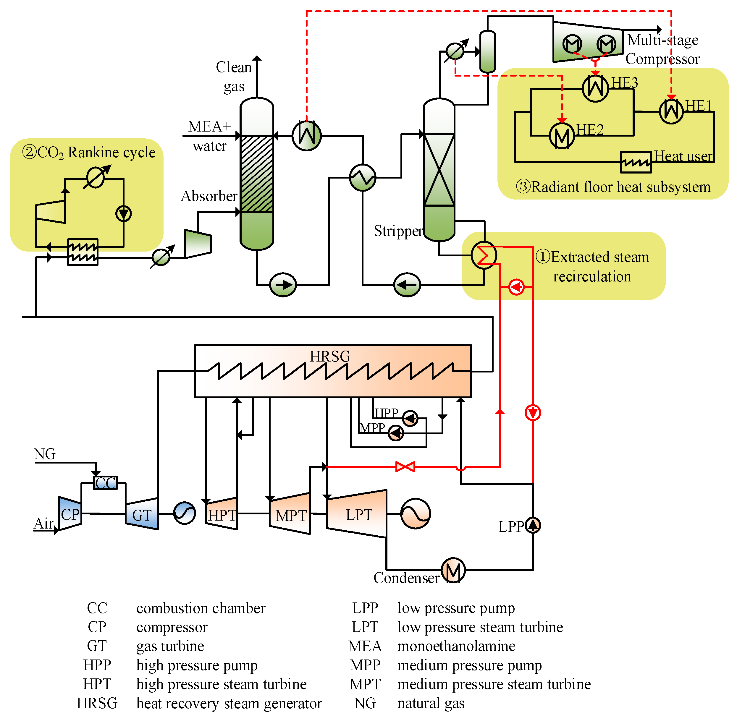
2.3. Description of the Improved De-Carbonization NGCC Power Plant Integrated with Heat Supply

In view of the energy flow characteristics of CO2 capture process, especially the three parts of energy loss as mentioned in Section 2.2, a new configuration of the decarbonization NGCC power plant is proposed as shown in Figure 3. In the new system, three targeted measures are adopted to reuse the surplus energy from extracted steam, flue gas and CO2 capture subsystem, respectively.
• Extracted steam recirculation
In the improved system, the steam extracted from the steam turbine for CO2 capture is mixed with part of the reboiler condensate after going through the throttle to fully utilize the degree of superheating of the extracted steam and avoid absorbent degradation. Then the steam with suitable temperature and pressure subsequently releases the regeneration heat at the reboiler. The remainder of the condensate is recycled to the outlet of HRSG preheater, which further recovers the surplus heat of the extracted steam.
• CO2 Rankine cycle
Aiming to reuse the cooling heat of flue gas whose temperature is relative high (~120 °C), a CO2 Rankine cycle is introduced because of its lower critical parameters, making it suitable to recover the low-temperature sensible heat in the flue gas, as shown in Figure 3. In the CO2 Rankine cycle, the working fluid is heated firstly to 148.0 °C by flue gas and then expands to 7.00 MPa in the turbine. The exhausted working fluid is cooled down to 26.0 °C and sequentially pumped to 12.00 MPa to finish the circulation.
• Radiant floor heat subsystem
A radiant floor heat subsystem is employed to utilize the low-grade and large flowrate heat in the CO2 capture subsystem. Specifically, the heating water (40.0 °C) goes through heat exchanger 1 (HE1) to absorb the heat from the absorbent cooler and is then divided into two branches. One is heated by the captured CO2 in HE2 and the other is heated by a multi-stage compressor intercooler in HE3. Afterwards, the heating water with proper temperature (70.0 °C) flows into the radiant floor system user releasing heat and then goes back to HE1 to finish the circulation.

3. Case Study

3.1. Main Assumptions and Case Description

To reveal the impacts of the three integration measures on the thermal performance of de-carbonization NGCC power plant, the following three cases are thoroughly simulated and thermodynamically analyzed in this section:
  • Base case: NGCC power plant without CO2 capture
  • Case 1: De-carbonization NGCC power plant without system integration
  • Case 2: De-carbonization NGCC power plant with system integration
A 555 MW NGCC power plant is selected as the Base case in this study [28]. The pressure ratio of the gas turbine cycle and the flue gas temperature at GT inlet is set to 18.5 and 1371.0 °C, respectively. While the feed NG is formed primarily of methane (93.1 mol %), it also includes ethane (3.2 mol %), propane (0.7 mol %), n-butane (0.4 mol %), CO2 (1.0 mol %) and nitrogen (1.6 mol %). Other parameters needed for the simulation are listed in Table 1.

3.2. Simulation Basis

In this study, three cases are simulated within UniSim Design R450, which can be used to determine energy-efficient solutions (including the identification of the most appropriate operating conditions) [9,29]. The relevant thermodynamic data for the CO2 capture subsystem was calculated by using the Amine package/Li-Mather method. For the gas turbine subsystem and steam turbine subsystem, the Peng-Robinson package and ASME-Steam package were used respectively. Particularly, the block models “Conversion Reactor”, “Expander”, “Heat Exchanger”, “Absorber Column” and “Distillation Column” are selected for establishing the combustion chamber, the steam/gas turbines, the HRSG, the absorber and the stripper. Meanwhile, some additional block model are adopted to finish the simulation, such as “Compressor,” “Heat Exchanger”, “Cooler”, “Pump” and so on.

3.3. Evaluation Criteria

For the conventional power generation unit, the net efficiency is commonly considered to evaluate the thermal performance of the whole power plants, which is the ratio of the power output to the total energy input and can be calculated as follows:
η e = 3600 × P g e n M × Q L  
Here, η e is the net efficiency, Pgen is the net power output (MW), M is the total amount of fossil fuel input to the boiler per unit time (kmol/h), QL is the LHV of fuel (kJ/kmol), 3600 can be considered as 3600 s/h.
For the new system, it not only generates electric power, but also supplies heat for the radiant floor user. Therefore, the overall energy efficiency ( η f ) is also adopted for comprehensive thermodynamic performance evaluation, which can be defined as follows [29,30,31,32]:
η f = 3600 × ( P g e n + E q ) M × Q L  
where, E q is the valid heat supplied to the radiant floor heat subsystem (MW).

4. Results and Discussion

4.1. Thermodynamic Performance

Based on the simulation and calculation above, Table 2 shows the main thermodynamic analysis results of these three cases. The net power output of the NGCC power plant is reduced by 115.40 MW due to the implementation of CO2 capture, which is about 21% of the net power output in NGCC power plant without CO2 capture.
Particularly, 130.56 kg/s of extracted steam is sent to the reboiler, which is ~90% of the total steam flowrate at MPT outlet, meaning a 91.43 MW decrease of the LPT power output; secondly, 24.98 MW extra electricity is consumed by auxiliary facilities in CO2 capture subsystem, including the boost fan, circulating pumps and multi-stage compressor. Due to the above two aspects, the efficiency penalty of CO2 capture reaches to 11.6 percentage points in the NGCC power plant.
In the proposed system, the net power output increases from 445.87 to 465.35 MW by adopting three measures, resulting in 2.0 percentage points reduction in the efficiency penalty of CO2 capture compared with Case 1.
Specifically, the degree of superheating of the extracted steam is fully utilized through extracted steam recirculation, which reduces the extracted steam flowrate by 18.61 kg/s and simultaneously increases the LPT power output by 10.44 MW. In addition, the rest reboiler condensate is injected into the HRSG preheater outlet to further utilize the surplus heat of extracted steam, increasing the flue gas temperature at HRSG outlet from 122.3 to 161.1 °C. All these waste heat in the flue gas (161.1–40.0 °C) can be recovered to generate electricity in the CO2 Rankine cycle, which makes the net power output of NGCC increases by 9.09 MW. Therefore, the net power plant efficiency improves from 44.8% to 46.8% without consideration of heat supply.
Moreover, in the heating season, most of the low-grade waste heat in CO2 capture subsystem can be utilized by the radiant floor heat subsystem. As shown in Figure 3, the energy for the radiant floor heat subsystem includes three parts. Specifically, the heating water flows through HE1 and absorbs 212.58 MW heat from the absorbent cooler, then it is divided into two branches. 76% is delivered to HE2 and absorbs 23.65MW heat from the captured CO2 stream with the temperature range of 94.7 to 71.0 °C and the rest enters HE3 to recover 11.36 MW heat from the multi-stage compressor intercooler. In this way, 247.59 MW heat can be supplied to the radiant floor users, which could increase the overall energy efficiency from 44.8% to 71.6%.

4.2. Energy Analysis for the CO2 Capture Process

The energy flow diagrams of CO2 capture process in Case 1 and Case 2 are shown in Figure 4 to reveal the essence of energy saving in the integrated system.
The energy input of Case 1 reaches 519.44 MW, including thermal energy brought by extracted steam (387.00 MW), sensible heat brought by flue gas (107.46 MW) and the electric power consumption (24.98 MW). These energy drives the process of CO2 capture and absorbent regeneration, then degrades into low-temperature waste heat, which is quantitatively equal of the energy input and generally taken away by cooling water in the extracted steam cooler, flue gas cooler and the coolers in CO2 capture subsystem, leading to a huge energy penalty, remarkable cooling water requirement and potential thermal pollution.
Through system integration, a large amount of waste energy, originally taken away by cooling water in Case 1, can be efficiently recovered and effectively utilized. Firstly, 42.81 MW waste heat of extracted steam is recovered by the extracted steam recirculation, decreasing the extracted steam energy input from 387.00 to 330.19 MW with constant regeneration heat (292.23 MW). Secondly, the waste energy in flue gas cooler (135.75 MW) is utilized to generate electric power by the CO2 Rankine cycle. It is noted that the exhausted heat from flue gas cooler in the Case 2 is greater than that in Case 1, due to the increase of the inlet temperature of the flue gas cooler. This is because part of the condensate from reboiler is injected to the outlet of HRSG preheater, which means less condensed water is available to recover the heat from the flue gas in preheater of HRSG, leading to an increase of flue gas temperature at HRSG outlet (i.e., the temperature at the inlet of the flue gas cooler). Thirdly, 247.59 MW waste heat from CO2 capture subsystem is recovered by radiant floor heat subsystem, resulting in ~80% reduction in the total cooling heat losses of CO2 capture subsystem as compared with the Case 1. By utilizing the above three measures, the total energy losses of the CO2 capture process decrease from 519.44 to 79.29 MW with a reduced energy input by 56.82 MW and the overall energy efficiency of the new system can be improved significantly to 71.6%.

4.3. Techno-Economic Analysis

4.3.1. Techno-Economic Criteria

Techno-economic analysis is conducted to reveal the comprehensive performance of these three systems. The cost of electricity (COE) and the cost of CO2 avoided (COA) are selected as the evaluation criteria. The COE ($/MWh) is calculated as follows:
C O E = ( β × C 0 + C f + C v × C F H × C H ) / ( P × C F )  
where β is the capital recovery factor; C0 is the total overnight cost (TOC) ($); Cf is the fixed Operation & Maintenance (OM) cost ($); Cv is the variable OM cost ($); H is the annual heat supply capacity (GJ); CH is the heat price ($/GJ); P is the annual net power output (kW); CF is the capacity factor.
The COA ($/tCO2) is defined by Kreutz et al. [33] as follows:
C O A = ( C O E c a p C O E r e f ) / ( E r r e f E r c a p )  
where COEcap is the COE of the system with CO2 capture ($/kWh); COEref is the COE of the system without CO2 capture ($/kWh); Ercap is the CO2 emission rate of the system with CO2 capture (kg/kWh); Erref is the CO2 emission rate of the system without CO2 capture (kg/kWh).
To get the TOC of the new system, every added equipment cost should be estimated by utilizing the actual cost and the proper scaling factors, which can be calculated as follows [34]:
C E = C B × ( Q / Q B ) M  
where Q is the scaling parameter; QB is the reference parameter; CE is the estimated equipment cost with capacity Q; CB is the known equipment cost with capacity QB; M is the scale factor, which is constant specific to unit type.

4.3.2. Techno-Economic Assumptions

In this study, some economic assumptions are adopted. Specifically, (1) the NG price is 6.89 $/GJ LHV; (2) the OM costs are fixed at 4% of the TOC; (3) CF is assumed to be 85%; (4) the specific overnight cost of NGCC power plant is 718 $/kW [28]; (5) the CO2 capture subsystem cost of a 555 MW NGCC power plant with 90% CO2 capture efficiency is 311 M$ [28]; (6) the heat price is 5.32 $/GJ [35]; (7) the capital recovery factor is 0.105 [28]; and (8) the equipment lifespan is 30 years. Other parameters needed for estimating the added equipment costs of the integration measures are listed in Table 3.

4.3.3. Techno-Economic Results

The techno-economic performances are shown in Figure 5, including the changes of the TOC, net power output, COE, and COA of these three cases. As the results show, the TOC of the NGCC power plant increases by ~80% due to the implementation of carbon capture and the net power output of Case 1 is reduced by 115.40 MW because of the extracted steam for absorbent regeneration and the auxiliary power consumption in CO2 capture subsystem. These two effects result in a 28.54 $/MWh increase of the COE, which is 49% higher than that of the NGCC power plant without CO2 capture.
In the improved system, three measures are adopted to alleviate the energy consumption for CO2 capture, causing $19.00 M increase of the TOC. The power output of the new integration system is19.48 MW higher than the power output of Case 1. Moreover, in the heating period, 247.59 MW heat is recovered for the radiant floor heat subsystem, which brings extra benefit for NGCC power plant. Therefore, the COE and COA of the new system decreases to 80.11 $/MWh and 70.39 $/t CO2, which are 7.2% and 22.3% lower than that of Case 1 respectively.

5. Conclusions

With the continuing concern about carbon emissions around the world, CO2 capture technologies have attracted more and more attention. Not only are large amounts of energy consumed for absorbent regeneration, but the process also causes some operation and safety issues, which hinder its large scale application. Therefore, it is important to pay attention to the system integration between the energy utilization system and CO2 capture process aiming to recover the low-grade energy and reduce the energy penalty.
In this study, an improved system of NGCC power plant with CO2 capture and heat supply was developed, which recovers the sensible heat of flue gas to generate electricity through a CO2 Rankine cycle and reutilizes the relative low heat released from the CO2 capture subsystem for a radiant floor heating subsystem. Through thermodynamic and techno-economic analysis, the integrated measures cause only 2.6% enhancement of the total investment, but the power output is 4.4% higher than that for the decarbonization NGCC power plant without integration and 247.59 MW heat can be supplied to the radiant floor users as well. Therefore, the COE and COA of the new system are much lower than that of the decarbonization NGCC power plant without integration.
In summary, the integration measures proposed in this study are effective in enhancing the net efficiency of power plants with a reasonable increment of investment, which provides an efficient and economic option for CO2 removal from NGCC power plants.

Author Contributions

Y.H. and Y.G. designed the models and wrote the paper. G.X. gave the conceptualization of the new system. H.L. and S.D. reviewed and improved the manuscript.

Funding

This research was funded by the National Key R&D Program of China (No. 2017YFB0603300), the International Science & Technology Cooperation Program of China (No. 2016YFE0124300), the International Science and technology cooperation project of Wuhan science and Technology Bureau (No. 2017030209020254), and the young talents program of Hubei provincial education department (No. Q20181402).

Conflicts of Interest

The authors declare no conflicts of interest.

References

  1. Climate Change 2007 Synthesis Report. Available online: http://www.ipcc.ch/pdf/assessment-report/ar4/syr/ar4_syr_full_report.pdf (accessed on 28 October 2018).
  2. Climate Change 2014 Mitigation of Climate Change, Working Group III Contribution to the Fifth Assessment Report of the Intergovernmental Panel on Climate Change. Available online: http://www.ipcc.ch/pdf/assessment-report/ar5/wg3/ipcc_wg3_ar5_full.pdf (accessed on 28 October 2018).
  3. Yamagata, Y. Global negative emission land use scenarios and their ecological implications. In Encyclopedia of Ecology, 2nd ed.; Fath, B., Ed.; Elsevier: New York, NY, USA, 2019; Volume 4, pp. 96–107. ISBN 978-0-444-64130-4. [Google Scholar]
  4. Budinis, S.; Krevor, S.; Mac Dowell, N.; Brandon, N.; Hawkes, A. An assessment of CCS costs barriers and potential. Energy Strategy Rev. 2018, 22, 61–81. [Google Scholar] [CrossRef]
  5. Zhang, Z.; Li, Y.F.; Zhang, W.X.; Wang, J.L.; Soltanian, M.R.; Olabi, A.G. Effectiveness of amino acid salt solutions in capturing CO2: A review. Renew. Sustain. Energy Rev. 2018, 98, 179–188. [Google Scholar] [CrossRef]
  6. Zareiekordshouli, F.; Lashanizadehgan, A.; Darvishi, P. Experimental and theoretical study of CO2 solubility under high pressure conditions in the ionic liquid 1-ethyl-3-methylimidazolium acetate. J. Supercrit. Fluid 2018, 133, 195–210. [Google Scholar] [CrossRef]
  7. Yu, H. Recent developments in aqueous ammonia-based post-combustion CO2 capture technologies. Chin. J. Chem. Eng. 2018, in press. [Google Scholar] [CrossRef]
  8. Mores, P.L.; Manassaldi, J.I.; Scenna, N.J.; Caballero, J.A.; Mussati, M.C.; Mussati, S.F. Optimization of the design operating conditions and coupling configuration of combined cycle power plants and CO2 capture processes by minimizing the mitigation cost. Chem. Eng. J. 2018, 331, 870–894. [Google Scholar] [CrossRef]
  9. Prentza, L.; Koronaki, I.P.; Papoutsis, E.G.; Papaefthimiou, V.D. Dynamic simulation and parametric sensitivity study in reactive CO2 capture systems—A solvent comparison study. Therm. Sci. Eng. Prog. 2018, 5, 555–567. [Google Scholar] [CrossRef]
  10. Herraiz, L.; Fernández, E.S.; Palfi, E.; Lucquiaud, M. Selective exhaust gas recirculation in combined cycle gas turbine power plants with post-combustion CO2 capture. Int. J. Greenh. Gas Control 2018, 71, 303–321. [Google Scholar] [CrossRef]
  11. Wang, C.; Li, S.; Liu, F.; Gao, L.; Sui, J. Post combustion CO2 capture in power plant using low temperature steam upgraded by double absorption heat transformer. Appl. Energy 2018, 227, 603–612. [Google Scholar] [CrossRef]
  12. Cau, G.; Tola, V.; Ferrara, F.; Porcu, A.; Pettinau, A. CO2-free coal-fired power generation by partial oxy-fuel and post-combustion CO2 capture: Techno-economic analysis. Fuel 2018, 214, 423–435. [Google Scholar] [CrossRef]
  13. Oh, S.Y.; Yun, S.; Kin, J.K. Process integration and design for maximizing energy efficiency of a coal-fired power plant integrated with amine-based CO2 capture process. Appl. Energy 2018, 216, 311–322. [Google Scholar] [CrossRef]
  14. Rio, M.S.; Gibbins, J.; Lucquiaud, M. On the retrofitting and repowering of coal power plants with post-combustion carbon capture: An advanced integration option with a gas turbine windbox. Int. J. Greenh. Gas Control 2017, 58, 299–311. [Google Scholar] [CrossRef]
  15. Yu, Y.S.; Li, Y.; Li, Q.; Jiang, J.; Zhang, Z.X. An innovative process for simultaneous removal of CO2 and SO2 from flue gas of a power plant by energy integration. Energy Convers. Manag. 2009, 50, 2885–2892. [Google Scholar] [CrossRef]
  16. Ystad, P.A.M.; Lakew, A.A.; Bolland, O. Integration of low-temperature transcritical CO2 Rankine cycle in natural gas-fired combined cycle (NGCC) with post-combustion CO2 capture. Int. J. Greenh. Gas Control 2013, 12, 213–219. [Google Scholar] [CrossRef]
  17. Kurtulus, K.; Coskun, A.; Ameen, S.; Yilmaz, C.; Bolatturk, A. Thermoeconomic analysis of a CO2 compression system using waste heat into the regenerative organic Rankine cycle. Energy Convers. Manag. 2018, 168, 588–598. [Google Scholar] [CrossRef]
  18. Zhai, R.R.; Yu, H.; Chen, Y.; Li, K.K.; Yang, Y.P. Integration of the 660MW supercritical steam cycle with the NH3-based CO2 capture process: System integration mechanism and general correlation of energy penalty. Int. J. Greenh. Gas Control 2018, 72, 117–129. [Google Scholar] [CrossRef]
  19. Alie, C.; Backham, L.; Croiset, E.; Douglas, P.L. Simulation of CO2 capture using MEA scrubbing: A flowsheet decomposition method. Energy Convers. Manag. 2005, 46, 475–487. [Google Scholar] [CrossRef]
  20. Bonaventura, D.; Chacartegui, R.; Valverde, J.M.; Becerra, J.A.; Ortiz, C.; Lizana, J. Dry carbonate process for CO2 capture and storage: Integration with solar thermal power. Renew. Sustain. Energy Rev. 2018, 82, 1796–1812. [Google Scholar] [CrossRef]
  21. Xu, C.; Zhang, Q.; Yang, Z.P.; Li, X.S.; Xu, G.; Yang, Y.P. An improved supercritical coal-fired power generation system incorporating a supplementary supercritical CO2 cycle. Appl. Energy 2018, in press. [Google Scholar] [CrossRef]
  22. Adams, T.; Mac Dowell, N. Off-design point modelling of a 420 MW CCGT power plant integrated with an amine-based post-combustion CO2 capture and compression process. Appl. Energy 2016, 178, 681–702. [Google Scholar] [CrossRef]
  23. Luo, X.; Wang, M.; Chen, J. Heat integration of natural gas combined cycle power plant integrated with post-combustion CO2 capture and compression. Fuel 2015, 151, 110–117. [Google Scholar] [CrossRef]
  24. Rezazadeh, F.; Gale, W.F.; Akram, M.; Hughes, K.J.; Pourkashanian, M. Performance evaluation and optimisation of post combustion CO2, capture processes for natural gas applications at pilot scale via a verified rate-based model. Int. J. Greenh. Gas Control 2016, 53, 243–253. [Google Scholar] [CrossRef]
  25. Liu, X.; Chen, J.; Luo, X.; Wang, M.; Meng, H. Study on heat integration of supercritical coal-fired power plant with post-combustion CO2, capture process through process simulation. Fuel 2015, 158, 625–633. [Google Scholar] [CrossRef]
  26. Xu, G.; Wu, Y.; Yang, Y.; Zhang, K.; Song, X. A novel integrated system with power generation CO2 capture and heat supply. Appl. Therm. Eng. 2013, 61, 110–120. [Google Scholar] [CrossRef]
  27. Reddick, C.; Sorin, M.; Rheault, F. Energy savings in CO2, (carbon dioxide) capture using ejectors for waste heat upgrading. Energy 2014, 65, 200–208. [Google Scholar] [CrossRef]
  28. Cost and Performance Baseline for Fossil Energy Power Plants, Volume 1, Bituminous Coal and Natural Gas to Electricity. Available online: http://www.netl.doe.gov/File%20Library/Research/Energy%20Analysis/OE/BitBase_FinRep_Rev2a-3_20130919_1.pdf (accessed on 25 September 2018).
  29. Ozcan, D.C.; Ahn, H.; Brandani, S. Process integration of a Ca-looping carbon capture process in a cement plant. Int. J. Greenh. Gas Control 2013, 19, 530–540. [Google Scholar] [CrossRef] [Green Version]
  30. Li, P.; Nord, N.; Ertesvåg, I.S.; Ge, Z.; Yang, Z.; Yang, Y. Integrated multiscale simulation of combined heat and power based district heating system. Energy Convers. Manag. 2015, 106, 337–354. [Google Scholar] [CrossRef]
  31. Solli, C.; Anantharaman, R.; Strømman, A.H.; Zhang, X.; Hertwich, E.G. Evaluation of different CHP options for refinery integration in the context of a low carbon future. Int. J. Greenh. Gas Control 2009, 3, 152–160. [Google Scholar] [CrossRef]
  32. Kuramochi, T.; Ramírez, A.; Faaij, A.; Turkenburg, W. Post-combustion CO2 capture from part-load industrial NGCCCHPs, selected results. Energy Procedia 2009, 1, 1395–1402. [Google Scholar] [CrossRef]
  33. Kreutz, T.; Williams, R.; Consonni, S.; Chiesa, P. Co-production of hydrogen, electricity and CO2 from coal with commercially ready technology. Part B: Economic analysis. Int. J. Hydrogen Energy 2005, 30, 769–784. [Google Scholar] [CrossRef]
  34. Frey, H.C.; Zhu, Y. 11–Techno-economic analysis of combined cycle systems. Comb. Cycle Syst. Near-Zero Emiss. Power Gener. 2012, 306–328. [Google Scholar] [CrossRef]
  35. Tianjin Development and Reform Commission, Heat Price. Available online: http://fzgg.tj.gov.cn/gzcx/syjgcx/gr/201307/t20130705_30045.shtml (accessed on 25 September 2018).
  36. Campanari, S.; Chiesa, P.; Manzolini, G.; Bedogni, S. Economic analysis of CO2 capture from natural gas combined cycles using molten carbonate fuel cells. Appl. Energy 2014, 130, 562–573. [Google Scholar] [CrossRef]
  37. Guo, Z.; Wang, Q.; Fang, M.; Luo, Z.; Cen, K. Thermodynamic and economic analysis of polygeneration system integrating atmospheric pressure coal pyrolysis technology with circulating fluidized bed power plant. Appl. Energy 2014, 113, 1301–1314. [Google Scholar] [CrossRef]
Figure 1. Schematic of a typical NGCC power plant with CO2 capture.
Energies 11 03055 g001
Figure 2. Energy flow schematic of a MEA-based CO2 capture process.
Energies 11 03055 g002
Figure 3. Schematic of a new configuration of NGCC power plant with CO2 capture.
Energies 11 03055 g003
Figure 4. Energy flow diagram of the CO2 capture process in (a) Case 1 and (b) Case 2.
Energies 11 03055 g004
Figure 5. Techno-economic performance graph.
Energies 11 03055 g005
Table 1. Main parameters for the case simulation.
Gas Turbine Cycle
 Gas turbine typeAdvanced F Class
 Air mass flowrate (t/h)3143.00
 Nature gas flowrate (kmol/h)4380.00
 Low heat value (LHV) of NG (kJ/kmol)817,955.00
Steam Turbine Cycle
Temperature (°C)Pressure (MPa)Flowrate (t/h)
 HPT inlet steam560.016.65392.50
 MPT inlet steam560.02.48467.20
 LPT inlet steam329.70.52509.30
 HPT exhaust steam304.12.69392.50
 MPT exhaust steam334.20.52467.20
 Condensate water38.80.90514.20
CO2 Capture Subsystem
 CO2 recovery ratio (%)90
 Absorber pressure (MPa)0.10
 Reboiler pressure (MPa)0.22
 Pressure drop in column (MPa)0.01
 Multi-stage compressor
  1st stage outlet pressure (MPa)0.60
  2nd stage outlet pressure (MPa)1.70
  3rd stage outlet pressure (MPa)5.10
  4th stage outlet pressure (MPa)15.00
Table 2. Thermal performance comparison for Base case, Case 1 and Case 2.
Classified PerformanceBase CaseCase 1Case 2
Power consumed by air compressor (MW)449.31449.31449.31
GT power output (MW)823.26823.26823.26
HPT power output (MW)48.3348.3348.33
MPT power output (MW)59.7659.7659.76
LPT power output (MW)95.153.7214.15
Auxiliary power (MW)9.5734.5539.08
Net power output (MW)561.27445.87465.35
Fuel molar LHV (kJ/kmol)817,955817,955817,955
Flowrate of NG (kmol/h)438043804380
Flue gas outlet temperature of HRSG (°C)122.4122.3161.1
CO2 flowrate entering CO2 capture subsystem (kg/s)56.2056.2056.20
Specific regeneration heat (GJ/tCO2)——5.185.18
Flowrate of extracted steam (kg/s)——130.56111.94
Heat recovery in absorbent cooler (MW)————212.58
Heat recovery in extracted stream (MW)————23.65
Heat recovery in captured CO2 (MW)————11.36
Power generated by CO2 Rankin cycle (MW)————13.69
Pump power in CO2 Rankin cycle (MW)————4.61
Heat recovery by CO2 Rankin cycle (MW)————135.94
Net efficiency (%)56.444.8046.76
Overall energy efficiency (%)56.444.8071.64
Table 3. Main data for equipment cost estimation.
ComponentScaling ParameterCB (M$)QBMQ
Heat exchanger
HE1Heat transferred (MW)1.64 a57.20 a0.90 a212.58
HE2Heat transferred (MW)1.64 a57.20 a0.90 a23.65
HE3Heat transferred (MW)1.64 a57.20 a0.90 a7.93
CO2 Rankine cycle
TurbinePower output (MW)30.77 a200.00 a0.67 a13.69
PumpVolume flow (m3/h)0.02 b250.00 b0.14 b2487.10
HEHeat transferred (MW)1.64 a57.20 a0.90 a135.94
CondenserHeat transferred (MW)1.64 a57.20 a0.90 a126.85
Extracted stem pretreatment
PumpVolume flow (m3/h)0.02 b250 b0.140 b74.26
a Cost is taken from Campanari et al. [36]; b Cost is quoted from Guo et al. [37].

