Article

Fuzzy Supervision Based-Pitch Angle Control of a Tidal Stream Generator for a Disturbed Tidal Input

1
Automatic Control Group—ACG, Department of Automatic Control and Systems Engineering, Engineering School of Bilbao, University of the Basque Country (UPV/EHU), 48012 Bilbao, Spain
2
Laboratory of Research in Automatic Control—LA.R.A, National Engineering School of Tunis (ENIT), University of Tunis El Manar, 1002 Tunis, Tunisia
3
Department of Applied Mechanics, University Dunarea de Jos of Galati, Galati 800008, Romania
*
Author to whom correspondence should be addressed.
Energies 2018, 11(11), 2989; https://doi.org/10.3390/en11112989
Submission received: 30 September 2018 / Revised: 23 October 2018 / Accepted: 27 October 2018 / Published: 1 November 2018
(This article belongs to the Special Issue Offshore Renewable Energy: Ocean Waves, Tides and Offshore Wind)

Abstract

:
Energy originating in tidal and ocean currents appears to be more intense and predictable than other renewables. In this area of research, the Tidal Stream Generator (TSG) power plant is one of the most recent forms of renewable energy to be developed. The main feature of this energy converter is related to the input resource which is the tidal current speed. Since its behaviour is variable and with disturbances, these systems must be able to maintain performance despite the input variations. This article deals with the design and control of a tidal stream converter system. The Fuzzy Gain Scheduling (FGS) technique is used to control the blade pitch angle of the turbine, in order to protect the plant in the case of a strong tidal range. Rotational speed control is investigated by means of the back-to-back power converters. The optimal speed is provided using the Maximum Power Point Tracking (MPPT) strategy to harness maximum power from the tidal speed. To verify the robustness of the developed methods, two scenarios of a disturbed tidal resource with regular and irregular conditions are considered. The performed results prove the output power optimization and adaptive change of the pitch angle control to maintain the plant within the tolerable limits.

1. Introduction

Renewable energy consumption is predicted to grow in the range of 2.6% per year between 2012 and 2040 [1]. The increase in economic and structural changes will impact world energy consumption. Furthermore, with the development of countries and improvement of living conditions, the need for energy will increase rapidly [2,3]. The consumption of energy grew in the International Energy Outlook (IEO) 2016 Reference case [1]. The impact of fossil fuel dangers on the human environment and rising oil prices has prompted an expanded use of non-fossil renewable energy converters [4]. The worldwide energy demand is constantly increasing due to the evolution of modern society. Conventional energy sources, such as oil, gas, coal, and nuclear, are either at, or near the limits of their ability to grow in annual supply and will dwindle as the decades go forward [5]. The depletion of fossil fuel reserves, global warming due to CO2 emissions, the spread of health problems and increasing political tensions are some of the reasons why renewable energy should be promoted [6]. Research works have recently focused on renewable energy scavenging technologies which produce energy with small scale power. These technologies include triboelectric, nanogenerator and piezoelectric [7,8]. On large scale power, the switch to renewable energy sources should be done while fostering an evolution of personal, institutional and national values. These steps recognize the ultimate limits of the earth’s carrying capacities which are presently being dramatically exceeded.
Tidal current energy, which harnesses the kinetic energy contained in tidal streams, is emerging as a great potential energy source [9,10]. It has a number of advantages compared to other renewable energies. The resource predictability, the minimal visual impact and land occupation, its high load factor and sustainability are some of the noteworthy features [11,12]. The benefits include reduced reliance on imported fuels, uninterrupted and affordable energy supplies, long-term price stability, decoupling hydrocarbon and resource risks, and environmental security [13]. However, realistic tidal locations are very perturbed with high range and disturbances are site-specific [14,15]. The swell considers the crucial phenomenon to be taken into account which affects the maritime structures [16]. The propagation of the submarine swell has the greatest influence on the marine current and the origin of the disturbance in small time scales for the tidal turbine. One can note that the harnessed output power will be affected in the case of a disturbed input. The turbulence must be estimated from field observations of the flow, which are inherently sparse and noisy [17].
Many studies concentrated on the optimization of the generated power in the case of high tidal speed using the angular position of the rotor’s blades [18,19]. The pitch and stall angle controls have been developed in [20]. The work points out that the blade pitch angle control leads to more valuable responses concerning the energy yields than the stall regulated system. Some studies used the pitch angle control with several techniques [21]. Artificial intelligence has been used to handle renewable energy systems [22,23,24]. An artificial neural network is a designed method which is considered to solve many tasks of fitting applications. As detailed in [25], an artificial neural network has been conceived for the Tidal Stream Generator (TSG) to find the appropriate angle for each tidal speed variation. The study shows favourable results when compared with a conventional controller. The fuzzy reasoning approach is motivated by the flexibility in decision-making processes [26]. Interest in fuzzy logic has shown good results in the field of automatic control and the aim to extended it to renewable energy converters. This paper introduces a fuzzy rule-based scheme for gain scheduling of the pitch angle controller in power limitation mode. An adaptive fuzzy Proportional Integral Derivative (PID) controller with a gains scheduling mechanism is proposed. The fuzzy supervisor provides the gains to the controller in order to govern the blade pitch angle. The Maximum Power Point Tracking (MPPT) technique is used to generate the adequate trajectory to the rotational speed controller.
The remainder of this paper is structured as follows; Section 2 defines the realistic tidal site as a site evaluation tool for the tidal stream generator. Then, the design of the TSG system in a digital environment including the hydrodynamic, mechanical and electrical parts of the power plant is given in Section 3. Section 4 is devoted to the control objectives and strategies and presents the FGS-PID controller for the pitch angle control. Two study cases have been considered to test the investigated control approaches as presented in Section 5. Section 6 ends the paper with concluding remarks.

2. Alderney Race Tidal Site Profile

The Alderney Race is a straight located between the Channel Island of Alderney and Cap de la Hague on the West coast of France. The site is four meters wide and lies between Race rock ( 49 42 N, 2 08 W) and a rocky bank with a minimum depth of 17 m over it, which lies approximately 3.5 m from Cap de la Hague. The tides run in a northwesterly direction for a period of six hours starting at six hours before Dover High Water (DHW). After that, it switches direction to flow southeast for approximately six hours. The highest velocities are found on the east side. As an example, in the west of the La Foraine light buoy the spring current speed of the north going stream can reach 5 m/s and that of the south going stream is about 3.5 m/s [27].
This tidal site is an important profile for extracting marine energy because the density is large and the depths are suited for installing tidal stream turbines. One can note that the deployment of a TSG plant will have a huge load factor to generate electricity for a high time scale. Also, there are locations where the depth is about 30, 35 and 40 m which represents a suitable value for placing TSG plants. The local strength of the current is due to the acceleration of the tidal flow between the Alderney Island and La Hague cape (France). The average power density is around 5 kW/m 2 and depths varying between 30 and 60 m can be over a surface higher than 10 km 2 [27]. In this site, the data measurement of tidal velocities is provided by SHOM (French Navy Hydrographic and Oceanographic Service). As depicted in Figure 1, the propagation of tidal currents are spread over a wide range of values where high velocities can even exceed 4.5 m/s [28].
Fluctuation aspects of tidal power are based on two forms of energy disturbance: On a high time period corresponding to the neap and spring marine current changing each day, and on a small time period relating to swell effect phenomenon [29].

3. Model Statement

The development of high-efficiency tidal energy conversion systems requires multiple testings and continuous modifications to rapidly rectify and correct the behavior of the developed model. Therefore, it is better to perform these testings and rectifications in software in the loop framework. The structure of the TSG plant is illustrated in Figure 2. The tidal turbine is connected to the Doubly Fed Induction Generator (DFIG) via the drive train shaft. The hydrodynamic part is connected to the grid using the back-to-back power converters. In this sense, the dynamic modeling of the system requires the use of a computational tool including these nonlinear sub-models with a different timescale.

3.1. Tidal Turbine Model

The power generation from the marine current speed needs the hydrokinetic energy conversion to produce electrical power. It is described by the following equation [31]:
P t = 1 2 C p ( λ , β ) ρ π R 2 V 3
where V is the tidal current speed in (m/s), P t is the harnessed power from marine current (W), R is the rotor blade radius defined in (m), and ρ is the density of water (kg/m 3 ).
The kinetic power is corresponding to the speed of water V which passes through the channel section A as shown in Figure 3.
Bearing in mind that the TSG system can only extract a fraction of this available energy, so the power coefficient C p characterizes the level of performance of the tidal stream turbine. Such a coefficient is defined as function of the pitch angle β in (deg) and the tip-speed ratio λ , given as [32,33]:
λ = ω t R V
where ω t is the rotor speed in (rad/s).
The hydrodynamic torque of the tidal turbine, defined in (Nm), is expressed as follows:
T t s t = P t ω t

3.2. Mechanical Shaft Model

The mechanical transmission is used to transform the low rotational speed at the rotor to high one at the generator side. The high rotational speed of the generator is necessary to apply compact constructed generators. The model of the shaft is chosen so as to regroup the hydrodynamic loads of the tidal turbine since they represent an important factor relating to the extracted output power. Therefore, the rotor shaft is assumed an important aspect of the Tidal Stream Turbine (TST) which has an impact on the power fluctuations. The two-mass model is used to describe the rotor shaft dynamics as follows [34]:
T t s t T t = 2 H t d ω t d t
T t = D s h ( ω t ω g ) + K s h ( ω t ω g ) d t
T t T e m = 2 H g d ω g d t
where K s h in (Nm/rad) and D s h in (Nms/rad) are the stiffness and damping coefficients, respectively. T t is the torque of the rotor shaft in (Nm), T e m is the electromagnetic torque in (Nm), and ω g is the rotor speed in (rad/s). H t and H g are the inertia constants for the turbine and the generator in s, respectively.

3.3. Electrical Model

The hydrodynamic turbine should be able to operate over a wide range of tidal velocities in order to achieve optimum efficiency by tracking the optimal tip-speed ratio. Therefore, the DFIG system operates in both sub- and super-synchronous modes with a rotor speed range around the synchronous speed [35].
The model of the DFIG is given in the dq synchronous frame using the Park’s transformation as defined in [36]. The equations of the stator voltages and flux, in (V) and in (Wb) respectively, are written as follows:
U s d = R s I s d + d φ s d d t ω s φ s q U s q = R s I s q + d φ s q d t ω s φ s d
φ s d = L s I s d + L m I r d φ s q = L s I s q + L m I r q
The expressions of the rotor voltages and flux are given by the following equations:
U r d = R r I r d + d φ r d d t ω r φ r q U r q = R r I r q + d φ r q d t ω r φ r d
φ r d = L r I r d + L m I s d φ r q = L r I r q + L m I s q
The equation of the electromagnetic torque is defined as follows:
T e m = 3 2 p L m I s q I r d I s d I r q
where I s d , I s q are the stator currents given in (A), I r d , I r q are the rotor currents in (A), R s and R r are the resistances of the stator and rotor in ( Ω ) , ω s and ω r are the pulsations of the stator and rotor in (rad/s), L s and L r are the inductances of the stator and rotor in (H), respectively, L m is the magnetizing inductance in (H), and p is the number of the poles pairs.

3.4. Power Converters Model

Tidal stream converters aim to generate power and to guarantee cost reduction. For that reason, these systems use back-to-back power electronic converters since they ensure the connection with the grid [37]. These types of equipment ensure the conversion from a variable output frequency from the generator to a fixed one related to the grid [38]. The used back-to-back power converter includes the Rotor Side Converter (RSC) and the Grid Side Converter (GSC) which have been connected through the DC-link. This configuration has the advantage of applying the vector control method for both sides. The RSC is intended to control the operation of the generator. The aim of the GSC is to maintain constant voltage of the DC-link regardless of the magnitude and the direction of the rotor power.
The expressions of the active and reactive powers of the DFIG-based TST, in (W) and (VAR) respectively, are defined as:
P g = 3 2 U d g I d g U q g I q g
Q g = 3 2 U q g I d g U d g I q g
where U d g , U q g in (V) and I d g , I q g in (A) are the voltages and currents of the grid.
In order to achieve the voltage oriented control, the vectors of the d-axis and the grid voltage are aligned, U d g = U g and U q g = 0 . So, the equations of the active and reactive powers are rewritten as:
P g = 3 2 U g I d g
Q g = 3 2 U g I q g
The expression between the power stored in the DC-link and the power transferred to the grid is described as follows:
P g = 3 2 U g I d g = U d c I d c
where U d c and I d c are the voltage and current of the DC-link.

4. Control Strategies

When the tidal stream generators are subjected to turbulent tidal current speed and strong swells, the pitch angle control is investigated to limit the generated power and maintain the system safe from overload. For that reason, it’s important to study the system to optimize the extracted output power and to improve the efficiency. In this mode of operation, the pitch angle controller is set to regulate the pitch actuator when the marine current exceeds the threshold value, and thus maintain the generated power at its nominal condition. In each variable marine speed, the controller sends the adequate control signal in order to rotate the rotor blades to the desired angular position.
The power may be limited hydrodynamically using pitch control. The control scheme of the TSG power plant is depicted in Figure 4. Advanced control approaches are proposed in order to ensure better performances, especially to guarantee robustness under uncertainties. In this sense, the pitch angle control is investigated using the fuzzy logic approach in order to find the adaptive gains of the controller. Moreover, the rotational speed control is based on the MPPT strategy for which the maximum output power will be attained.

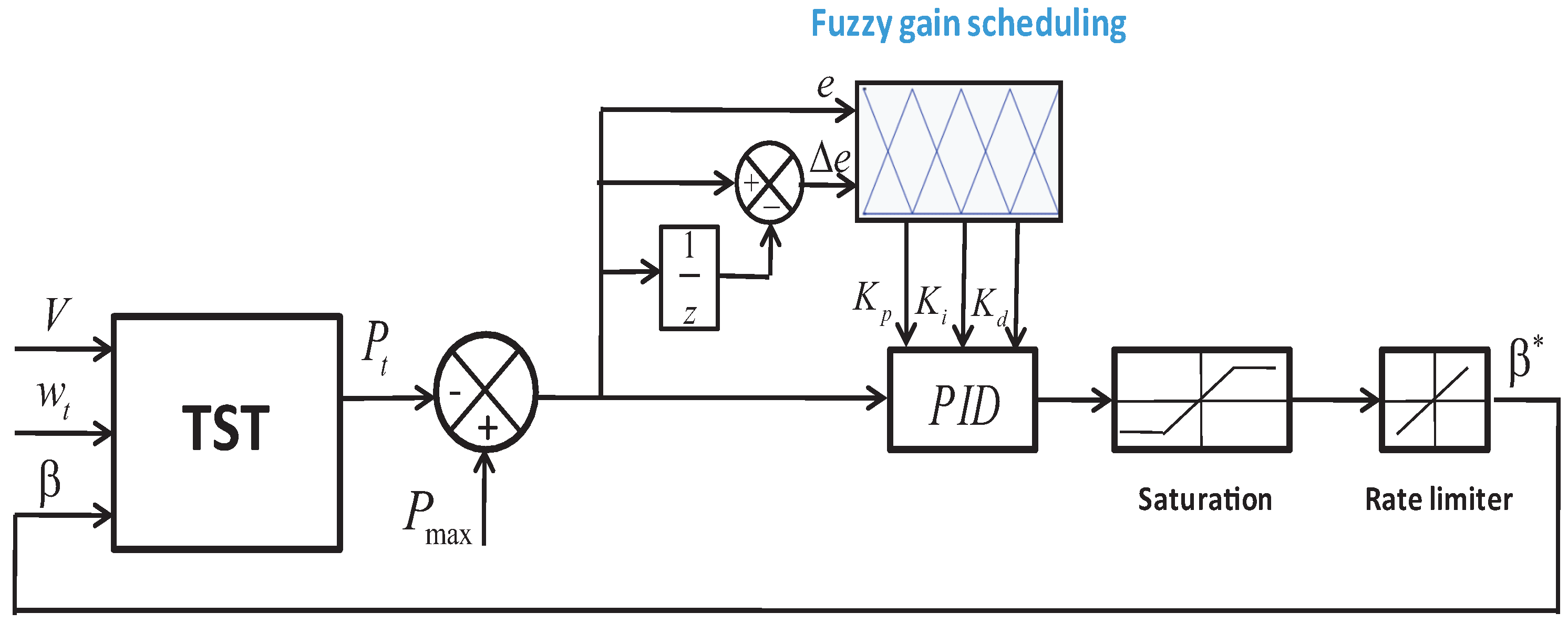
4.1. Pitch Angle Control

The proposed control scheme is illustrated in Figure 5. The pitch angle control loop is designed using a fuzzy gain scheduling method because it represents a robust control technique regarding model uncertainties [39,40]. The investigated Fuzzy Gain Scheduling (FGS)-based PID control is used to generate and tune the gains in order to keep the required performance. The input of the PID controller is the error between the maximum power supported by the system which is 1.5 MW and the measured generated power.
The approach taken here is to exploit fuzzy rules and reasoning [41,42]. The variation of the studied tidal turbine under different values of the pitch angle β is depicted in Figure 6. One can note that as the angle β increases as the output power P t decreases. The threshold value of the tidal velocity is calculated at 3.2 m/s. Over this value, the limitation mode will be used to protect the system.
The equation of the controller in the discrete-time domain is expressed as follows [39]:
u ( k ) = K p Δ e ( k ) + K i T s e ( k ) + K d Δ e ( k ) + u ( k 1 )
where e ( k ) is the error between P m a x and P t , Δ e ( k ) = e ( k ) e ( k 1 ) is the change of the error, T s is the sampling time and K p , K i and K d are the PID controller parameters.
The gains K p , K i and K d are normalized applying the linear transformation by the Equation (18) [43]:
K p = ( K p K p min ) / ( K p max K p min ) K i = ( K i K i min ) / ( K i max K i min ) K d = ( K d K d min ) / ( K d max K d min )
where K p min , K p max , K i min , K i max and K d min , K d max are the prescribed domains of the controller parameters.
The gain scheduling of the PID controller is calculated by means of the fuzzy rules given as follows:
i f e ( k ) i s A i a n d Δ e ( k ) i s B i t h e n K p i s C i a n d K i i s D i a n d K d i s E i
where A i , B i , C i , D i and E i are the fuzzy sets on the relating linguistic variables where i = 1 , 2 , , m .
The types of membership functions used are triangular uniformly distributed and symmetrical in the universe of discourse. The corresponding linguistic levels are Negative Big (NB), Negative (N), Zero (Z), Positive (P) and Positive Big (PB) as shown by Figure 7 and Figure 8.
The fuzzy rules proposed in this study are defined in Table 1, Table 2 and Table 3. The set of rules are proposed to fit the behavior of a PID conventionnel controller regarding the error and the error variation.
The equation of the defuzzification is described as follows:
K p = i = 1 m μ i μ C i K i = i = 1 m μ i μ D i K d = i = 1 m μ i μ E i
The decision-making output is calculated using a Max-Min fuzzy inference where the real outputs are calculated by the method of defuzzification center of gravity as:
K p = K p min + ( K p max K p min ) K p K i = K i min + ( K i max K i min ) K i K d = K d min + ( K d max K d min ) K d
By designing the fuzzy supervisor of the pitch controller based on the proposed fuzzy rules, the resulting fuzzy surfaces related to the gains K p , K i and K d are illustrated in Figure 9, Figure 10 and Figure 11, respectively.

4.2. Rotational Speed Control

4.2.1. RSC Control Design

The control scheme related to the RSC component is illustrated in Figure 12. The stator flux oriented control is used in this study. The design of the control scheme includes one control loop to regulate the rotor speed and two control loops to regulate the currents.
The MPPT generating the desired rotor speed to the outer loop is designed for the tidal turbine. It takes into account the characteristic curve shown in Figure 13 to follow the maximum power [44].
In this sense, the MPPT will generate the optimum rotational speed depending on the tidal current speed. Using the developed MPPT for TSG, ω r e f is defined as the rotational speed control for which a reference signal is set to the rotor current q-axis i q r * . The current control loops calculate the reference signal of the rotor voltage defined in dq synchronous frame. The expressions of the rotor voltages and currents are given by the following equations as defined in [45]:
U d r = R r i d r + σ L r d i d r d t U q r = R r i q r + σ L r d i q r d t
where σ is the leakage factor.
Also, the parameters of decoupling are added to the equations of the direct and quadrature component of the rotor voltages so as to improve the response of the system [46]. Therefore, the voltage references are given as follows:
U d r * = ω s l i p σ L r i q r + ( K P i e d + K I i e d d t ) U q r * = ω s l i p ( L m i m + σ L r i d r ) + ( K P i e d + K I i e d d t )
where ω s l i p is the angular frequency of the slip given in (rad/s) and i m is the current of stator magnetizing kept constant. K P i and K I i are the Proportional Integral (PI) controller parameters.
The PI controllers blocks are designed using the well-known Ziegler-Nichols method [47]. Also, a modification of the tuning on the first value of the parameters of the controller has been applied by means of the method robust response time algorithm [48]. The voltage references of the rotor are converted to the a b c frame which will affect the RSC component through the Pulse Width Modulation (PWM) block.

4.2.2. GSC Control Design

The control scheme design of the GSC component is illustrated in Figure 14. The used method is the voltage oriented control. This strategy consists of two PI controllers for the current and one PI controller for the voltage. The investigated block design controls the voltage U d c and the reactive power Q g . In order to extract the phase of the input signal θ g , the Phase Locked Loop (PLL) method is used in this study. The direct and quadrature components of the currents and voltages are obtained using Park’s transformation method.
The expressions of the grid voltages given in the d q synchronous frame as:
U g d = i d s R g + L g d i d s d t ω s L g i q s + U g d 1 U g q = i q s R g + L g d i q s d t ω s L g i d s + U g q 1
where R g is the resistance of the grid given in ( Ω ) , L g is the inductance of the grid in (H), U g d 1 and U g q 1 are the two phases of the terminal voltages.
The active and reactive powers are controlled via the currents synchronous frame d q . The controllers of the currents are identical and give the grid reference voltages U d s * and U q s * . In order to enhance the system response, the compensator parameters and feed-forward voltages are added to the control signals [49]:
U g d * = U g d + Ω g L g i q ( K P i e d + K I i e d d t ) U g q * = U g q Ω g L g i d ( K P i e q + K I i e q d t )
The voltage controller is conceived to control the DC-link voltage in the way to maintain it at its reference. The i q s current is intended to regulate the reactive power. The reference signal of the current in q-axis is considered zero. As the case of the RSC component, the PI controller parameters are calculated by means of the Ziegler-Nichols technique. Furthermore, the reference signals of the voltages are transformed to the a b c frame and will give the PWM signals for the GSC component.

5. Validation Results and Discussion

In this section, based on the realistic tidal site Alderney Race profile two study cases were used to test the robustness and the effectiveness of the investigated control methods. The adaptive FGS-PID based control was analyzed regarding the disturbance in the tidal speed under regular and irregular profiles. The numerical implementation of the TSG in a digital environment including the hydrodynamic, mechanical and electrical parts of the power plant is shown in Figure 15 using the model parameters listed in Table 4.
In this first case, the sensibility of the proposed FGS-PID based pitch angle control was tested under a long time fluctuation of the tidal resource in the case of turbulence as depicted in Figure 16. The input considered has the shape of a regular neap and spring tides with a pic values of about 4 m/s and 4.5 m/s, respectively.
The TSG control performances are illustrated in Figure 17. The power coefficient and the blade pitch angle curves are time varying for compensating to input disturbance. The FGS-PID based control provides the adaptive parameters of the pitch controller to respond to the behavior of the input change.
The generator speed response and the reference signal following the MPPT block are given in Figure 18. A zoom into the response within 1.2 s shows that the investigated control approach is robust regarding the speed tracking.
The generated power variation is illustrated in Figure 19. The resulting power changes according to the variation of the marine velocity. It can be noted that the control schemes are able to limit the extracted power within a specific limit of about 1.497 MW.
In the second case, the investigated control approach was analyzed regarding the swell effect disturbance which represents a short time fluctuation regarding the current speed input. The turbulent resource characteristic is shown in Figure 20. The average value taken is approximately about 3.7 m/s. The fluctuated tidal input admits a minimum value of 2.312 m/s and a maximum value of 5.022 m/s.
Figure 21 shows the power coefficient and the pitch angle variations. It is obvious that the system adapts well to the short-time fluctuations. At high tidal speed reached, the power coefficient decreases and consequently the pitch angle signal increases.
The response of the rotor speed and the reference gathered from the developed MPPT method are given in Figure 22. The controller shows a good tracking performance of the reference signal. This demonstrates that the FGS-PID based control has a reduced steady-state error due to the fact that the integral action is adequately changing regarding the variation of the tidal input.
The response of the generated power is illustrated in Figure 23. It can be seen that the power is limited to 1.496 MW. So, the system is able to optimize the extracted power in the case of the disturbed input under the swell effect phenomenon.

6. Conclusions

In this paper, a TSG system has been modeled and controlled. A fuzzy supervision has been conceived to the pitch controller in order to properly modify the gains of the PID in accordance with the variation of the tidal input. The MPPT strategy has been used to give the adequate rotational speed for the RSC control.
To test the robustness of the novel FGS-PID-based control the realistic tidal site Alderney Race site was investigated. The first experiment was performed using regular tidal speed under disturbance conditions. The results demonstrate that the control strategies successfully deal with these fluctuations which enable the plant to optimize the generated power.
A second case of study was used which considers a turbulent tidal profile under the swell effect disturbance. Simulation results show that the proposed control strategies are effective in terms of speed tracking and power regulation. Moreover, the sensitivity of the proposed fuzzy-based control strategy has been analyzed regarding the swell effect. The investigated control schemes seem to be a good solution when the resource is not well-known and even if the resource is heavily disturbed.
The dynamic performances of the tidal stream generator system have been evaluated versus intelligence control technique. The proposed fuzzy supervisor ensures the regulation of the blade pitch angle for the high marine currents. The sensitivity of the proposed control strategy has been analyzed regarding the swell effect. Indeed, any variation of the fluid speed consequently induces a variation of the rotor speed reference which is deduced from the MPPT strategy.

Author Contributions

Conceptualization, K.G., I.G., and A.J.G.; Formal Analysis, K.G.; Investigation, K.G.; Methodology, K.G.; Project administration, E.R.; Software, K.G.; Supervision, I.G., S.B., J.H. and A.J.G.; Writing, Review and Editing, K.G.

Funding

This research received no external funding.

Acknowledgments

This work was supported by the MINECO through the Research Project DPI2015-70075-R (MINECO/FEDER, UE) and in part by the University of the Basque Country (UPV/EHU) through PPG17/33. The authors would like to thank the collaboration of the Basque Energy Agency (EVE) through Agreement UPV/EHUEVE23/6/2011, the Spanish National Fusion Laboratory (EURATOM-CIEMAT) through Agreement UPV/EHUCIEMAT08/190 and EUSKAMPUS - Campus of international Excellence.

Conflicts of Interest

The authors declare no conflict of interest.

References

  1. International Energy Outlook 2016. International Energy Outlook 2016 With Projections to 2040; Tech. Report; U.S. Energy Information Administration, Office of Energy Analysis U.S. Department of Energy: Washington, DC, USA, 2016.
  2. Panwar, N.L.; Kaushik, S.C.; Kothari, S. Role of renewable energy sources in environmental protection: A review. Renew. Sustain. Energy Rev. 2011, 15, 1513–1524. [Google Scholar] [CrossRef]
  3. Ellabban, O.; Abu-Rub, H.; Blaabjerg, F. Renewable energy resources: Current status, future prospects and their enabling technology. Renew. Sustain. Energy Rev. 2014, 39, 748–764. [Google Scholar] [CrossRef]
  4. Frondel, M.; Ritter, N.; Schmidt, C.M.; Vance, C. Economic impacts from the promotion of renewable energy technologies: The German experience. Energy Policy 2010, 38, 4048–4056. [Google Scholar] [CrossRef] [Green Version]
  5. Grino Colom, M. Power Generation From Tidal Currents; Application to Ria de Vigo; Escola de Comins, Departament d’Enginyeria Hidraulica, Maritima i Ambiental (DEHMA): Barcelone, Spain, 2015. [Google Scholar]
  6. Shapiro, G.I. Effect of tidal stream power generation on the region-wide circulation in a shallow sea. Ocean Sci. 2011, 7, 165–174. [Google Scholar] [CrossRef] [Green Version]
  7. Zhu, G.; Lin, Z.H.; Jing, Q.; Bai, P.; Pan, C.; Yang, Y.; Zhou, Y.; Wang, Z.L. Toward large-scale energy harvesting by a nanoparticle-enhanced triboelectric nanogenerator. Nano Lett. 2013, 13, 847–853. [Google Scholar] [CrossRef] [PubMed]
  8. Wang, S.; Lin, L.; Wang, Z.L. Nanoscale triboelectric-effect-enabled energy conversion for sustainably powering portable electronics. Nano Lett. 2012, 12, 6339–6346. [Google Scholar] [CrossRef] [PubMed]
  9. Uihlein, A.; Magagna, D. Wave and tidal current energy—A review of the current state of research beyond technology. Renew. Sustain. Energy Rev. 2016, 58, 1070–1081. [Google Scholar] [CrossRef]
  10. Esteban, M.; Leary, D. Current developments and future prospects of offshore wind and ocean energy. Appl. Energy 2012, 90, 128–136. [Google Scholar] [CrossRef]
  11. APEC Energy Working Group. Marine and Ocean Energy Development An Introduction for Practitioners in APEC Economies; Technical Report; Institute of Lifelong Education: Moscow, Russia, 2013.
  12. Collin, A.J.; Nambiar, A.J.; Bould, D.; Whitby, B.; Moonem, M.A.; Schenkman, B.; Kiprakis, A.E. Electrical Components for Marine Renewable Energy Arrays: A Techno-Economic Review. Energies 2017, 10, 1973. [Google Scholar] [CrossRef]
  13. Inger, R.; Attrill, M.J.; Bearhop, S.; Broderick, A.C.; Grecian, W.J.; Hodgson, D.J.; Godley, B.J. Marine renewable energy: Potential benefits to biodiversity? An urgent call for research. J. Appl. Ecol. 2009, 46, 1145–1153. [Google Scholar] [CrossRef]
  14. Blackmore, T.; Myers, L.E.; Bahaj, A.S. Effects of turbulence on tidal turbines: Implications to performance, blade loads, and condition monitoring. Int. J. Mar. Energy 2016, 14, 1–26. [Google Scholar] [CrossRef] [Green Version]
  15. Walker, S.; Cappietti, L. Experimental Studies of Turbulent Intensity around a Tidal Turbine Support Structure. Energies 2017, 10, 497. [Google Scholar] [CrossRef]
  16. Wright, J.; Colling, A.; Park, D. (Eds.) Waves, Tides, and Shallow-Water Processes; Gulf Professional Publishing: Houston, TX, USA, 1999; Volume 4. [Google Scholar]
  17. Zhou, Z.; Benbouzid, M.; Charpentier, J.F.; Scuiller, F.; Tang, T. A review of energy storage technologies for marine current energy systems. Renew. Sustain. Energy Rev. 2013, 18, 390–400. [Google Scholar] [CrossRef] [Green Version]
  18. Ghefiri, K.; Bouallègue, S.; Haggège, J.; Garrido, I.; Garrido, A.J. Firefly algorithm based-pitch angle control of a tidal stream generator for power limitation mode. In Proceedings of the 2018 International Conference on Advanced Systems and Electric Technologies (IC ASET), Hammamet, Tunisia, 22–25 March 2018; pp. 387–392. [Google Scholar]
  19. Kirke, B.K.; Lazauskas, L. Limitations of fixed pitch Darrieus hydrokinetic turbines and the challenge of variable pitch. Renew. Energy 2011, 36, 893–897. [Google Scholar] [CrossRef]
  20. Whitby, B.; Ugalde-Loo, C.E. Performance of pitch and stall regulated tidal stream turbines. IEEE Trans. Sustain. Energy 2014, 5, 64–72. [Google Scholar] [CrossRef]
  21. Zhou, Z.; Scuiller, F.; Charpentier, J.F.; Benbouzid, M.; Tang, T. Power limitation control for a PMSG-based marine current turbine at high tidal speed and strong sea state. In Proceedings of the 2013 IEEE International Electric Machines & Drives Conference (IEMDC), Chicago, IL, USA, 12–15 May 2013. [Google Scholar]
  22. Kalogirou, S.A. Artificial neural networks in renewable energy systems applications: A review. Renew. Sustain. Energy Rev. 2001, 5, 373–401. [Google Scholar] [CrossRef]
  23. Manas, M.; Kumari, A.; Das, S. An Artificial Neural Network based Maximum Power Point Tracking method for photovoltaic system. In Proceedings of the 2016 International Conference on Recent Advances and Innovations in Engineering (ICRAIE), Jaipur, India, 23–25 December 2016; pp. 1–6. [Google Scholar]
  24. Ouammi, A.; Zejli, D.; Dagdougui, H.; Benchrifa, R. Artificial neural network analysis of Moroccan solar potential. Renew. Sustain. Energy Rev. 2012, 16, 4876–4889. [Google Scholar] [CrossRef]
  25. Ghefiri, K.; Bouallègue, S.; Garrido, I.; Garrido, A.J.; Haggège, J. Multi-Layer Artificial Neural Networks Based MPPT-Pitch Angle Control of a Tidal Stream Generator. Sensors 2018, 18, 1317. [Google Scholar] [CrossRef] [PubMed]
  26. Chang, C.S.; Fu, W. Area load frequency control using fuzzy gain scheduling of PI controllers. Electr. Power Syst. Res. 1997, 42, 145–152. [Google Scholar] [CrossRef]
  27. Thièbot, J.; du Bois, P.B.; Guillou, S. Numerical modeling of the effect of tidal stream turbines on the hydrodynamics and the sediment transport-Application to the Alderney Race (Raz Blanchard), France. Renew. Energy 2015, 75, 356–365. [Google Scholar] [CrossRef]
  28. SHOM. The Portal of Maritime and Coastal Geographic Information. Available online: http://www.shom.fr (accessed on 11 September 2018).
  29. Lewis, M.J.; Neill, S.P.; Hashemi, M.R.; Reza, M. Realistic wave conditions and their influence on quantifying the tidal stream energy resource. Appl. Energy 2014, 136, 495–508. [Google Scholar] [CrossRef]
  30. Ghefiri, K.; Garrido, I.; Bouallègue, S.; Haggège, J.; Garrido, A. Hybrid Neural Fuzzy Design-Based Rotational Speed Control of a Tidal Stream Generator Plant. Sustainability 2018, 10, 3746. [Google Scholar] [CrossRef]
  31. Ghefiri, K.; Bouallègue, S.; Garrido, I.; Garrido, A.J.; Haggège, J. Complementary Power Control for Doubly Fed Induction Generator-Based Tidal Stream Turbine Generation Plants. Energies 2017, 10, 862. [Google Scholar] [CrossRef]
  32. Ghefiri, K.; Bouallègue, S.; Haggège, J. Modeling and SIL simulation of a Tidal Stream device for marine energy conversion. In Proceedings of the 2015 6th International Renewable Energy Congress (IREC), Sousse, Tunisia, 24–26 March 2015; pp. 1–6. [Google Scholar]
  33. Elghali, S.E.B.; Balme, R.; Le Saux, K.; Benbouzid, M.E.H.; Charpentier, J.F.; Hauville, F. A simulation model for the evaluation of the electrical power potential harnessed by a marine current turbine. IEEE J. Ocean. Eng. 2007, 32, 786–797. [Google Scholar] [CrossRef] [Green Version]
  34. Fernandez, L.M.; Jurado, F.; Saenz, J.R. Aggregated dynamic model for wind farms with doubly fed induction generator wind turbines. Renew. Energy 2008, 33, 129–140. [Google Scholar] [CrossRef]
  35. Amundarain, M.; Alberdi, M.; Garrido, A.J.; Garrido, I. Modeling and simulation of wave energy generation plants: Output power control. IEEE Trans. Ind. Electron. 2011, 58, 105–117. [Google Scholar] [CrossRef]
  36. Alberdi, M.; Amundarain, M.; Garrido, A.J.; Garrido, I.; Maseda, F.J. Fault-ride-through capability of oscillating-water-column-based wave-power-generation plants equipped with doubly fed induction generator and airflow control. IEEE Trans. Ind. Electron. 2011, 58, 1501–1517. [Google Scholar] [CrossRef]
  37. Baroudi, J.A.; Dinavahi, V.; Knight, A.M. A review of power converter topologies for wind generators. Renew. Energy 2007, 32, 2369–2385. [Google Scholar] [CrossRef]
  38. Hu, J.; Nian, H.; Xu, H.; He, Y. Dynamic modeling and improved control of DFIG under distorted grid voltage conditions. IEEE Trans. Energy Convers. 2011, 26, 163–175. [Google Scholar] [CrossRef]
  39. Zhao, Z.Y.; Tomizuka, M.; Isaka, S. Fuzzy gain scheduling of PID controllers. IEEE Trans. Syst. Man Cybern. 1993, 23, 1392–1398. [Google Scholar] [CrossRef]
  40. Bouallègue, S.; Haggège, J.; Ayadi, M.; Benrejeb, M. PID-type fuzzy logic controller tuning based on particle swarm optimization. Eng. Appl. Artif. Intell. 2012, 25, 484–493. [Google Scholar] [CrossRef]
  41. Tursini, M.; Parasiliti, F.; Zhang, D. Real-time gain tuning of PI controllers for high-performance PMSM drives. IEEE Trans. Ind. Appl. 2002, 38, 1018–1026. [Google Scholar] [CrossRef]
  42. Bedoud, K.; Ali-rachedi, M.; Bahi, T.; Lakel, R. Adaptive fuzzy gain scheduling of PI controller for control of the wind energy conversion systems. Energy Procedia 2015, 74, 211–225. [Google Scholar] [CrossRef]
  43. Dounis, A.I.; Kofinas, P.; Alafodimos, C.; Tseles, D. Adaptive fuzzy gain scheduling PID controller for maximum power point tracking of photovoltaic system. Renew. Energy 2013, 60, 202–214. [Google Scholar] [CrossRef]
  44. Ghefiri, K.; Bouallègue, S.; Haggège, J.; Garrido, I.; Garrido, A.J. Modeling and MPPT control of a Tidal Stream Generator. In Proceedings of the 2017 4th International Conference on Control, Decision and Information Technologies (CoDIT), Barcelona, Spain, 5–7 April 2017; pp. 1003–1008. [Google Scholar]
  45. Pena, R.; Clare, J.C.; Asher, G.M. Doubly fed induction generator using back-to-back PWM converters and its application to variable-speed wind-energy generation. IEE Proc. 1996, 143, 231–241. [Google Scholar] [CrossRef]
  46. Twining, E.; Holmes, D.G. Grid current regulation of a three-phase voltage source inverter with an LCL input filter. IEEE Trans. Power Electron. 2003, 18, 888–895. [Google Scholar] [CrossRef]
  47. Astrom, K.J.; Hagglund, T. Advanced PID Control; ISA—The Instrumentation, Systems, and Automation Society, Research Triangle: Park, NC, USA, 2006. [Google Scholar]
  48. Vilanova, R.; Visioli, A. PID Control in the Third Millennium; Springer: London, UK, 2012. [Google Scholar]
  49. Blaabjerg, F.; Teodorescu, R.; Liserre, M.; Timbus, A.V. Overview of control and grid synchronization for distributed power generation systems. IEEE Trans. Ind. Electron. 2006, 53, 1398–1409. [Google Scholar] [CrossRef]
Figure 1. Tidal current speed in Alderney Race in the French western coast.
Energies 11 02989 g001
Figure 2. Scheme of the tidal stream generator system [30].
Energies 11 02989 g002
Figure 3. Tidal flow through the swept area of a rotor disk.
Energies 11 02989 g003
Figure 4. Tidal stream generator control scheme. TST, Doubly Fed Induction Generator (DFIG), Rotor Side Converter (RSC), Grid Side Converter (GSC), Maximum Power Point Tracking (MPPT).
Energies 11 02989 g004
Figure 5. Fuzzy Gain Scheduling (FGS)-Proportional Integral Derivative (PID) based pitch angle control scheme.
Energies 11 02989 g005
Figure 6. Output power versus the rotor speed for different blade pitch angles.
Energies 11 02989 g006
Figure 7. The inputs membership functions. Negative Big (NB), Negative (N), Zero (Z), Positive (P) and Positive Big (PB).
Energies 11 02989 g007
Figure 8. The outputs membership functions.
Energies 11 02989 g008
Figure 9. Fuzzy surface for K p gain.
Energies 11 02989 g009
Figure 10. Fuzzy surface for K i gain.
Energies 11 02989 g010
Figure 11. Fuzzy surface for K d gain.
Energies 11 02989 g011
Figure 12. RSC control scheme design.
Energies 11 02989 g012
Figure 13. Extracted power as a function of the rotor speed for different tidal speeds.
Energies 11 02989 g013
Figure 14. GSC control scheme design.
Energies 11 02989 g014
Figure 15. Model implementation of the TSG power plant.
Energies 11 02989 g015
Figure 16. Case 1: Regular turbulent tidal resource speed.
Energies 11 02989 g016
Figure 17. Control performances of case 1: (a) power coefficient variation; (b) pitch angle variation.
Energies 11 02989 g017
Figure 18. Case 1: Rotational speed and its reference curves.
Energies 11 02989 g018
Figure 19. Case 1: Output power variation.
Energies 11 02989 g019
Figure 20. Case 2: Irregular disturbed tidal speed input.
Energies 11 02989 g020
Figure 21. Control performances of case 2: (a) power coefficient variation; (b) pitch angle variation.
Energies 11 02989 g021
Figure 22. Case 2: Rotational speed and its reference curves.
Energies 11 02989 g022
Figure 23. Case 2: Output power variation.
Energies 11 02989 g023
Table 1. Fuzzy rules for K p gain [30].
e ( k ) / Δ e ( k ) NBNZPPB
NBNBNBNBNZ
NNBNNNZ
ZNBNZPPB
PZPPPPB
PBZPPBPBPB
Table 2. Fuzzy rules for K i gain [30].
e ( k ) / Δ e ( k ) NBNZPPB
NBPBPBPBNNB
NPBPPZNB
ZPPZNNB
PZPNNNB
PBZNNBNBNB
Table 3. Fuzzy rules for K d gain.
e ( k ) / Δ e ( k ) NBNZPPB
NBNBNBNBPPB
NNNNZPB
ZZNZPPB
PZNPPPB
PBZPPBPBPB
Table 4. Tidal Stream Generator (TSG) system parameters.
TurbineDrive-TrainDFIGConverter
ρ = 1027 kg/m 3 H t = 3 s P n = 1.5 MW V d c = 1150 V
R = 8 m H g = 0.5 s U r m s = 690 VC = 0.01 F
C p max = 0.44 K s h = 2 × 10 6 Nm/rad f r e q = 50 Hz
λ o p t = 6.96 D s h = 3.5 × 10 5 Nms/rad R s = 2.63 m Ω
V n = 3.2 m/s R r = 2.63 m Ω Choke
L s = 0.168 mH R g = 0.595 m Ω
L r = 0.133 mH L g = 0.157 mH
L m = 5.474 mH
p = 2

