Article

Validation of a Coupled Electrical and Hydrodynamic Simulation Model for a Vertical Axis Marine Current Energy Converter

Department of Engineering Sciences, Uppsala University, P.O. Box 534, 751 21 Uppsala, Sweden
*
Author to whom correspondence should be addressed.
Energies 2018, 11(11), 3067; https://doi.org/10.3390/en11113067
Submission received: 28 September 2018 / Revised: 30 October 2018 / Accepted: 30 October 2018 / Published: 7 November 2018
(This article belongs to the Special Issue Offshore Renewable Energy: Ocean Waves, Tides and Offshore Wind)

Abstract

:
This paper validates a simulation model that couples an electrical model in Simulink with a hydrodynamic vortex-model by comparing with experimental data. The simulated system is a vertical axis current turbine connected to a permanent magnet synchronous generator in a direct drive configuration. Experiments of load and no load operation were conducted to calibrate the losses of the turbine, generator and electrical system. The power capture curve of the turbine has been simulated as well as the behaviour of a step response for a change in tip speed ratio. The simulated results agree well with experimental data except at low rotational speed where the accuracy of the calibration of the drag losses is reduced.

1. Introduction

Ocean energy is a field of growing interest when it comes to renewable energy thanks to its high density of energy per unit area, and to the high predictability. Waves and ocean currents conversion is being investigated through different concepts [1]. Hydrokinetic energy conversion implies use of the energy in free-flowing water for conversion to electric energy. There are many types of hydrokinetic conversion systems being investigated, from different turbine configurations to non-turbine systems [2,3,4]. Resource characterization, developing the power conversion technology and the design of arrays are some of the biggest areas to develop if marine current energy will become economically viable [5,6]. Numerical modeling is often used to study marine current conversion. A full Computational Fluid Dynamics (CFD) model is computationally demanding for simulating the flow in and around turbines. Instead, other approaches to simplify model of the flow has been developed, and many of these models originate from wind turbine research that has been modified for water environment. The most commonly used models are the double multiple streamtube (DMST) [7], vortex [8,9] and Actuator Line Model (ALM) [10]. Since the goal of the energy conversion is to generate electricity, it could be a big advantage to have a simulation model that can simulate both the hydrodynamic behaviour as well as the electrical output. This paper presents a coupled model of an electrical system with an hydrodynamic free vortex model. The model is validated with experimental data.
The Marine Current Power project at Uppsala University is investigating the possibilities of using a Vertical Axis Current Turbine (VACT) connected to a Permanent Magnet Synchronous Generator (PMSG) in a direct drive configuration, see Figure 1. The system has many similarities with a wind power system but one of the main differences is that the converter is rotating slower, subjecting the turbine and generator to a higher torque. A prototype turbine and generator has been deployed in the river Dal (Dalälven) in Söderfors, Sweden [11]. Water speeds in the river are usually in the interval of 0.4–1.5 m/s [12]. The output voltage and rotational speed of the generator can be controlled using an electrical system comprising a load control using a passive diode-bridge rectifier connected via a DC bus to a resistive dump load trough a switch, described in more detail in [13]. Using the coupled model, different discharge scenarios in the river can be simulated that cannot be tested at the experimental site. Control strategies and electrical systems can be optimized for maximum power capture and safe operation.

2. The Söderfors Experimental Station

The experimental station has two acoustic doppler current profilers (ADCP), a turbine, a generator and a measurement cabin (housing control and measurement systems). The turbine and generator are placed approximately 800 m downstream of a conventional hydro power plant, at a depth of 7 m. The experimental station is fully described in [12,14].

2.1. The Turbine, the Generator and Load Control

The power in free-flowing water that reaches a turbine with cross-sectional area A is described by P w a t e r = 1 2 A ρ v 3 where v is the water speed and ρ is the density of water. For a vertical axis turbine the projected area is the diameter of the turbine times the height. The fraction of power absorbed by the turbine is called power coefficient, C P , defined as C P = P t u r b i n e P w a t e r . C P is a function of the tip speed ratio (TSR or λ ), i.e., the ratio of blade tip speed to undisturbed water speed, λ = ω r v , where ω is the angular speed of the turbine in rad/s and r the turbine radius in meters. The C P ( λ ) -curve for the turbine has been experimentally verified in [15] to have a maximum power coefficient at tip speed ratio 3.1 for a power coefficient of 0.26. The turbine parameters can be found in Table 1.
Power for a rotating body can be described as P = ω T where T is torque. When the generator and turbine are rotating, the difference between torque delivered by the turbine, T t , and the electrocmagnetic torque, T e will determine the acceleration of the rotor, d ω / d t , written as
d ω d t J = T t - T e
where J is the inertia of the rotating body. The electrical torque can be influenced by changing the magnitude of the resistive load. For a given water speed and resistive load, the rotational speed of the turbine and generator will settle at some value, resulting in a T t and T e . This is called load control because the magnitude of the resistive load is used for changing λ and thus controlling the power capture of the turbine.
For a Permanent Magnet Generator, the voltages of the generator are proportional to the rate of change of the magnetic flux established by the magnets, flux linkage, and to the rotational speed. For a slow-turning generator such as this one, the iron losses cannot be neglected as they can for the more common fast-turning generators. The efficiency of the generator was measured in [16] to be at least 80% in the range of 5–17 RPM. The parameters of the generator can be found in Table 1. After assembly of the turbine and generator, the iron losses and the losses in the seals and the bearings were estimated to be 350 ± 10 Nm times the rotational speed, presented in [17].

2.2. Electrical Layout and Control System

An enclosure containing all electrical components is located in the measurement cabin, see Figure 2. The entire system is controlled from LabVIEW using a CompactRIO and a FPGA module. The DC load operates at a switching frequency of 500 Hz and consists of a resistive load, a rectifier with a capacitor bank and an IGBT with a snubber circuit in parallel. The generator is connected to the measurement cabin by a three phase AC-power cable ~200 m long with a resistance of 0.08 Ω /phase.
The DC load components are explained in more detail in [13]. This section will give a summary of the load control. The Target DC voltage aims to keep the DC bus voltage within a user defined range using a P-regulator loop that uses the error of measured DC bus voltage minus set DC bus voltage as input. The loop has three states depending on the size of the error. If the error is negative, the duty cycle is set to 0%, which means it is operating without load, to accelerate the turbine. If the error is more than 5 V, the duty cycle is set to 100%, full load operation, to decelerate the turbine. In between 0 V and 5 V the loop enforces a linear relationship between error and duty cycle. Experimental results presented in [13] shows that the rotational speed can be set to operate with a variance of 4%. Further details of the control and measurement system can be found in [18].

2.3. Water Speed Measurements

The ADCPs are placed about 15 m upstream and 15 m downstream of the turbine. The ADCP devices are Workhorse Sentinel 1200 kHz with an accuracy of 0.3% of the water speed. Measurements are taken every 3.6 s and give a velocity profile from one meter above the bottom of the river to one meter below the surface. Since the upstream ADCP is placed 15 m upstream from the turbine there will be a 10–15 s delay, depending on the water speed, between the measurement of the water speed and when water reaches the turbine. For this paper the speed of the water at the ADCP is assumed to remain constant until reaching the turbine. In reality, since the cross sectional area of the river increases downstream of the first ADCP, the water speed at the turbine will be a few percent lower. For all water speed measurements in the paper, the average water speed will be given. The variance in water speed was less than 1% of the mean for all measurements unless otherwise stated.

3. Coupling of the Electrical and the Hydrodynamic Vortex Model

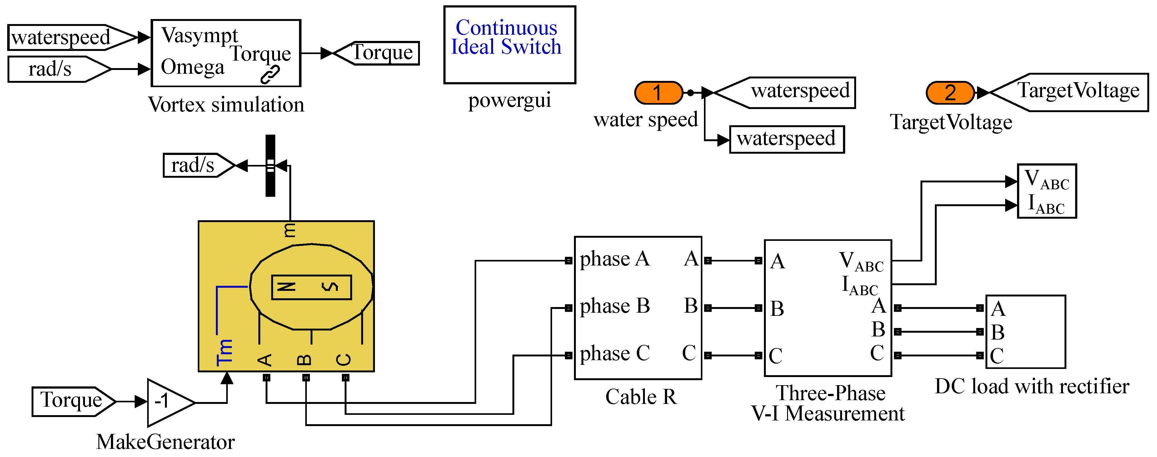
The model of the electrical system is made in Simulink and the vortex model is imported to Simulink as a function with rotational speed and water speed as inputs, and gives the turbine torque as output.

3.1. Electrical Model in Simulink

The electrical system consists of Power Electronics components, which includes fast switching of devices to control voltages and currents. Such fast switching puts demands on the simulation to be able to compute continuous states at small time steps. When the measured voltage is far from the target voltage it leads to a long state of transition for many steps in the simulation. In this transitional phase the rotational speed and the voltages of the generator may be changing rapidly, to then change slower as they settle around the respective target values. The switching frequency will be much higher than that of any simulated big physical change in the system which leads to many consecutive steps of little change until the next switching state. This type of system is called a stiff system. The setup was modelled using Matlab SIMULINKTM because of its p o w e r g u i blocks that have stiff solvers. Since the vortex code and the rest of the system updates at different time steps a variable step solver is best suited in order to maximize simulation speed and retain solver accuracy.
The Simulink model can be seen in Figure 3. The rectifier is modelled as a three phase passive diode bridge and the switch is an IGBT with a snubber circuit, see parameters in Table 2. The PWM duty cycle is determined by the size of the error described in Section 2.2.
The generator is modelled as a Permanent Magnet Synchronous Generator with a round rotor. It is a three phase machine with a sinusodial back electromotive force. The block is set to use torque as input and the outputs are three phase voltages and currents as well as rotational speed. The generator model does not account for the iron losses in the generator, and is instead included in the estimation of the losses related to the rotational speed, as discussed in Section 2.1.

3.2. Hydrodynamic Vortex Model for Vertixal Axis Turbines

The hydrodynamic part of the simulation model is implemented using a two-dimensional free vortex method. The vortex method is a time dependent mesh-free method where the vorticity generated from the blades are used as the discretization variable. The method is designed for infinite domains with no external boundaries, which considering the width of the river at the current site should be considered a reasonable approximation. As the method already is well described in literature, only a brief summary of the method will be given here. For more general information regarding the vortex method, see e.g., reference [19], and for a detailed description of the model implemented in the current work, see e.g., references [20,21,22].
The vortex method is combined with a force model for the hydrodynamic forces to avoid having to solve the boundary layer flow of the blades, which is computationally demanding. Instead, the flow velocities are calculated at the blade positions. This gives the local Reynolds number and the local angle of attack for each blade, which can be used to calculate the forces. Due to the unsteady nature of the flow, as the angle of attack is constantly changing for vertical axis turbines, experimental data for lift and drag coefficients [23] are combined with a Leishman Beddoes type dynamic stall model for the force calculations, see references [21,24]. The forces are used to determine the vorticity that is released from the blades, and with the current method, one vortex is released from each blade at each time step. The vortex propagation can be evaluated using the fast multipole method (the current implementation uses the CPU version of the code described in reference [25]), which makes the evaluation time approximately linear with the number of vortices in the simulation.
The current vortex method has been validated for wind turbine applications in references [21,22]. It can be noted that the accuracy of the force calculation model decreases as the angle of attack increases, which means that the accuracy of the simulation model can be expected to decrease for low tip speed ratios of the turbine, which correspond to high angles of attack.
As support arms and their attachments to the blades are not properly modelled in the two-dimensional vortex model, a correction model has been applied to account for these losses. By assuming that the drag force generated by these parts can be given by
F D = 1 2 C D ρ A V r e l 2 1 2 C D ρ A r Ω 2
where C D is the drag coefficient, V r e l is the relative water speed to the blade and Ω is the rotational speed, one can approximate the torque as
T = r F D C Ω 2
where C is a constant. This constant will be experimentally determined by allowing the turbine to rotate without any load to determine its freespin velocity. The turbine is then simulated using this rotational velocity, and the constant has been adapted to make the simulation model give zero torque at the freespin velocity.
With the current implementation of the vortex method, it is possible to take much larger time steps for the hydrodynamics than for the electrical system, too small time steps should be avoided for the hydrodynamics to maintain reasonable computational speeds. To account for the difference in required time steps, the vortex method will use Heuns method for the time stepping, and for force evaluations between two time steps, the values are linearly interpolated between the value from the start of the time step, and the intermediate value in Heuns method, which is an approximation of the value at the end of the time step.
For each simulation the turbine will rotate at least 60 revolutions, around 500 s, in order for the vortex code to establish a wake. The hydrodynamic model is imported to Simulink as a function in a block. It receives the water speed and rotational speed of the turbine and returns the computed torque.

4. Calibrating the Simulation Model

Data from operation of the turbine and generator at the experimental site will be used to separately calibrate the generator and turbine models.

4.1. Calibration of Generator and Electrical System Losses

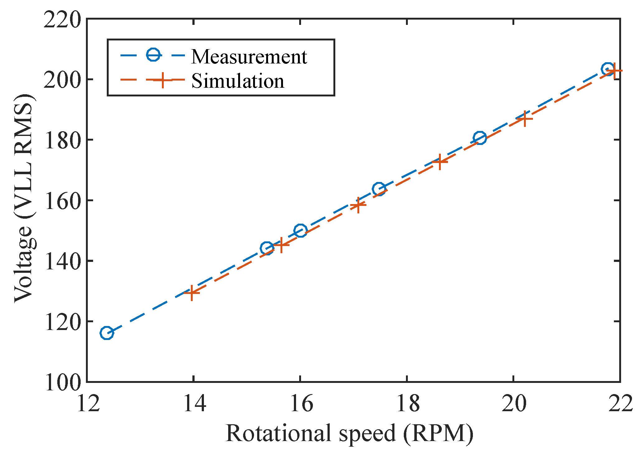
The generator model was implemented using the flux linkage, generator stator resistance and armature inductance from Table 1. The output voltage of the generator was calibrated by comparing the simulated generator voltage at no load operation with the measured output voltage of the generator. The RMS Line-to-Line voltage from six 30 m experiments during 2014 at different water speeds was recorded. The experimental and simulation results can be seen in Figure 4. The error between the measured and the simulated voltage was less than 1 %.
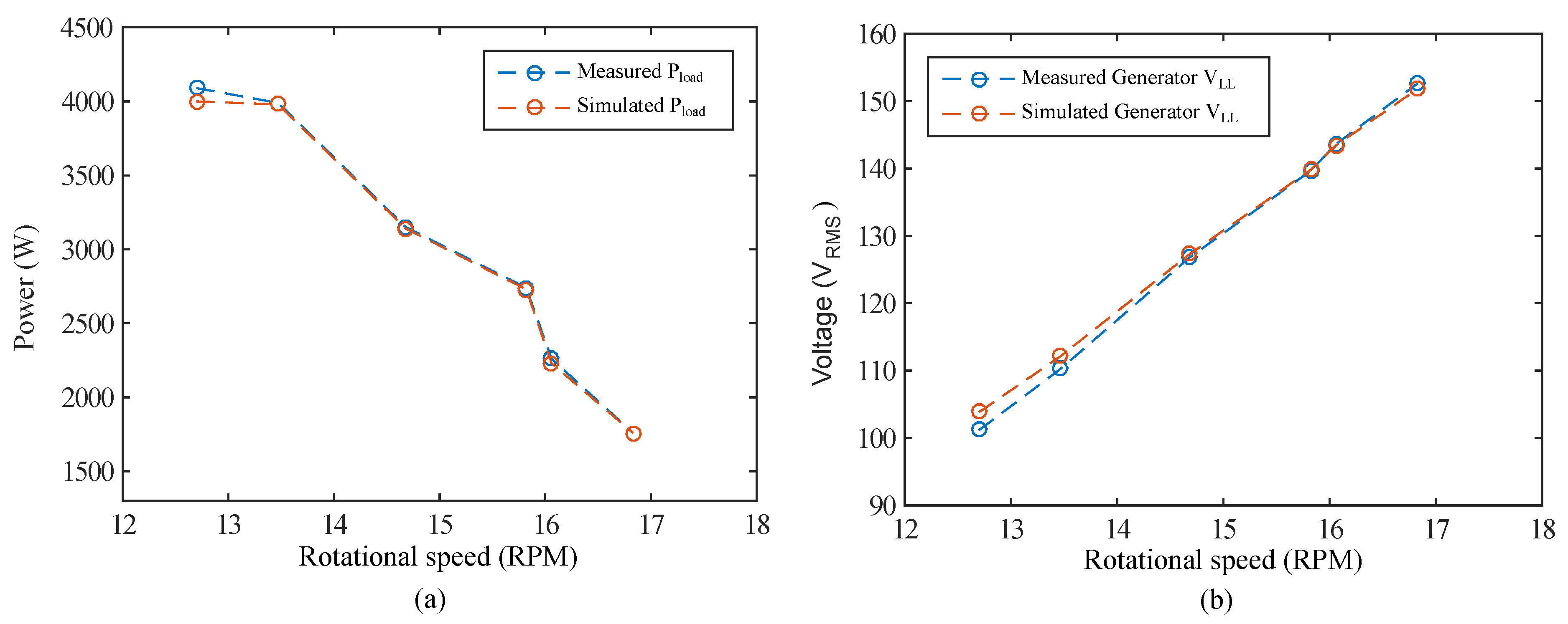
The model of the generator losses was calibrated using data from AC-load operation at the experimental site. Six load cases with resistive loads varying from 2.54 Ω to 13.0 Ω were carried out for 30 m each on the 20 and 21 January 2014 at around 1.3 m/s. The generator is given a fixed torque in the simulation that results in the same rotational speed for the generator as in the experiment. The simulated and measured power in the load is plotted in Figure 5a and the voltage over the load in Figure 5b. The simulations show good agreement except at the lowest rotational speed where the simulated power in the load is 2.2% lower and the simulated generator voltage 2.6% higher, showing that most probably the iron losses are overestimated at low rotational speed.

4.2. Calibration of Drag Losses

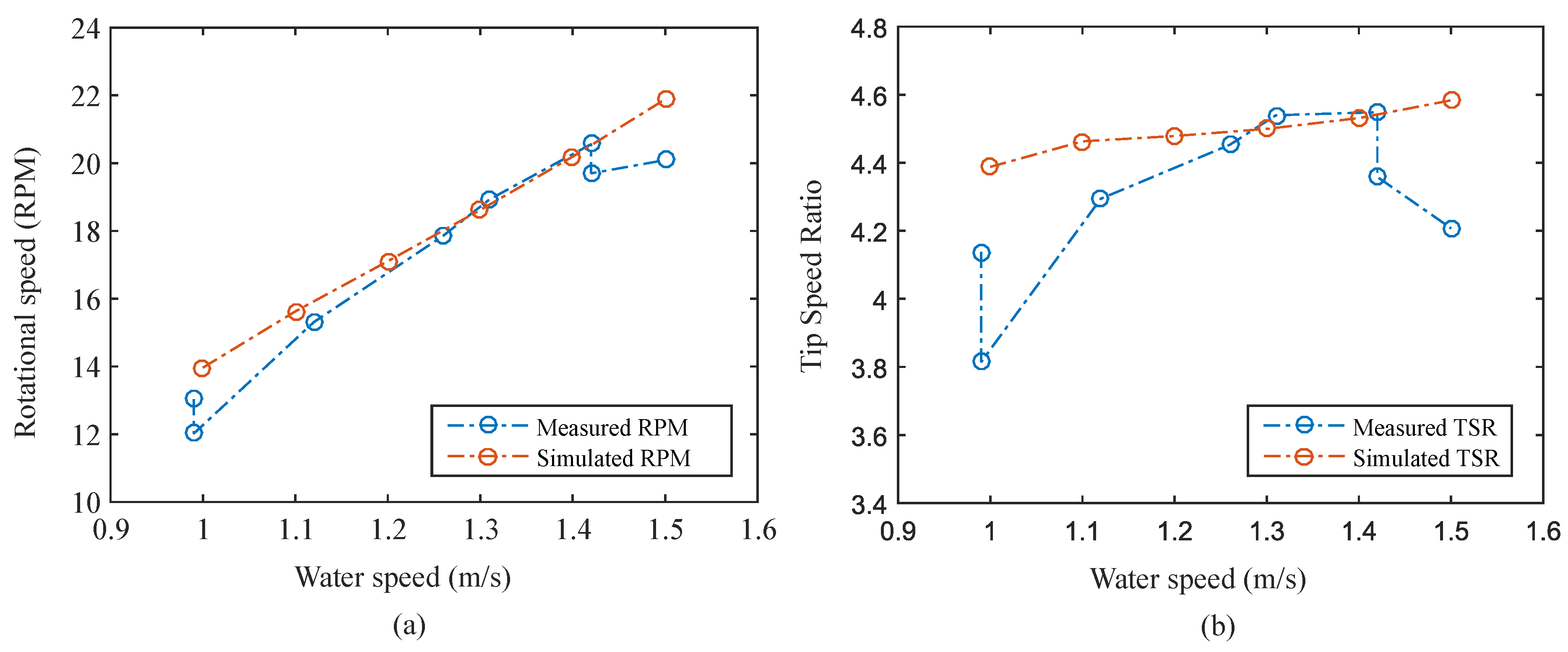
Freespin operation data at the experimental site will be used to calibrate the drag losses in Equation (2) of the turbine using a one parameter study. As discussed in Section 2.1, the iron losses and the losses in the seals and the bearings are set to 350 Nm. The turbine at the experimental site was operated without load for 30 m on 4 March 2014 at 1.42 m/s that resulted in a rotational speed of 20.5 RPM. This water speed and rotational speed was used as input to the vortex simulation where drag losses of 1000 Nms 2 was shown to give zero torque from the turbine. The hydrodynamic, electrical and mechanical torque giving losses dependent on the rotational speed are therefore estimated to be 350 + 1000 ω 2 Nm. The accuracy of the estimation of the drag losses will decrease the further away from this calibration point. The calibrated model of the turbine and generator was now simulated at free spin operation for a range of water speeds between 1 m/s and 1.5 m/s. The simulation is compared with experimental data recorded on 8 seperate occasions where the turbine operated for 30 m without load. The results are shown in Figure 6a,b. The simulation is able to predict the rotational speed of the turbine at free-spin around the rated water speed of the turbine (1.35 m/s). The rotational speed is 0.8% lower than the experiment around 1.35 m/s and 15.9% higher at low water speed. λ is 0.9% lower around 1.35 m/s and 15.9% higher at low water speed. The difference in simulated and measured rotational speed at low water speed is explained by the loss of accuracy of the turbine calibration since these points are far away from the calibration point. At high water speed, there is a sudden drop in the measured rotational speed. The authors have no explanation for this behaviour other than something exterior affecting the performance of the turbine. Before each measurement at the experimental site, there is no possibility of a visual inspection of the status of the turbine. On some occasions, the turbine was showing some unexpected behaviour. For instance, it could be unusually difficult to start the turbine and not be able to free spin at water speeds where it can usually do so, for only the problems to disappear the next day at the same water speed. These occasions have been written off as something exterior temporarily affecting the turbine, but could not be verified since there is no visual inspection equipment available on site. This could explain the discrepancy of the two rotational speeds measured at just below 1.0 m/s.

5. Validating the Simulation Model

Using the calibrated generator and turbine models from Section 4, the C P -curve for the turbine and step responses of DC-loads control can be simulated and compared with experimental results from the test site.

5.1. Simulations of the Power Capture of the Turbine

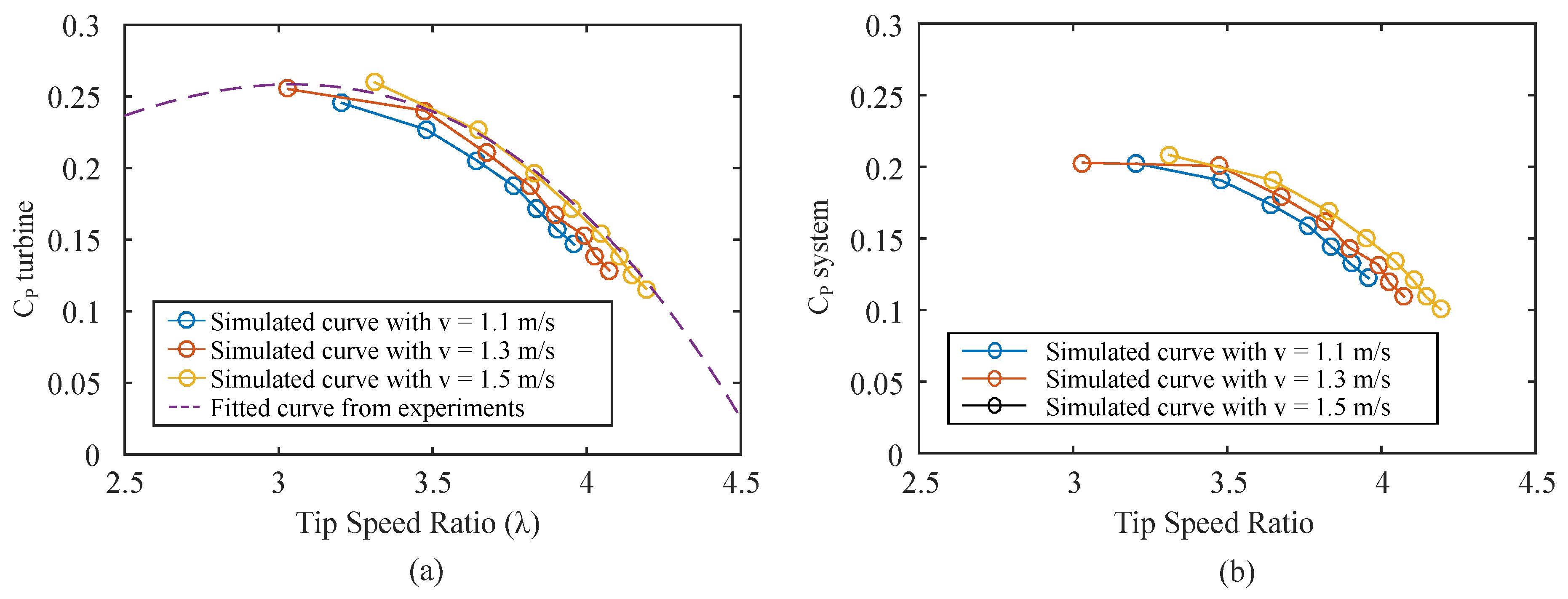
Experimental data at a range of water speeds and resistive AC-loads are in [15] used to investigate the performance of the turbine. In the study, the power produced by the turbine is estimated using the rotational speed of the turbine and by assuming that the power from the iron losses and mechanical losses in the generator are 180* ω plus the electrical power dissipated in the load. Hence the performance does not display only the hydrodynamic performance of the turbine. The results from the paper will be used to compare with the simulated C P -curve and referred to as the C P t u r b i n e . The power capture curve of the turbine for water speeds 1.1 m/s to 1.5 m/s and AC loads from 1 Ω to 9 Ω at steps of 1 Ω has been simulated. The simulation has been plotted together with the experimentally obtained fitted curve presented in [15] in Figure 7a. The experimentally measured efficiency of the total system, including all losses in the turbine and generator, is plotted in Figure 7b. The simulated C P t u r b i n e -curve shows good agreement with the experimental results. The power capture of the turbine increases as the water speed increases, because the Reynolds number increases that in turn reduces the drag losses.

5.2. Step Response of Change in Target DC Bus Voltage

The simulation model will also be evaluated on how well it can emulate the step response of the dc bus voltage and rotational speed for a change in λ . The torque output of the turbine will depend on the hydrodynamic model and the generator voltage and current will depend on the electrical model. The rise time and the overshoot will reveal how well the estimation of 3000 kgm 2 for the moment of inertia fits.
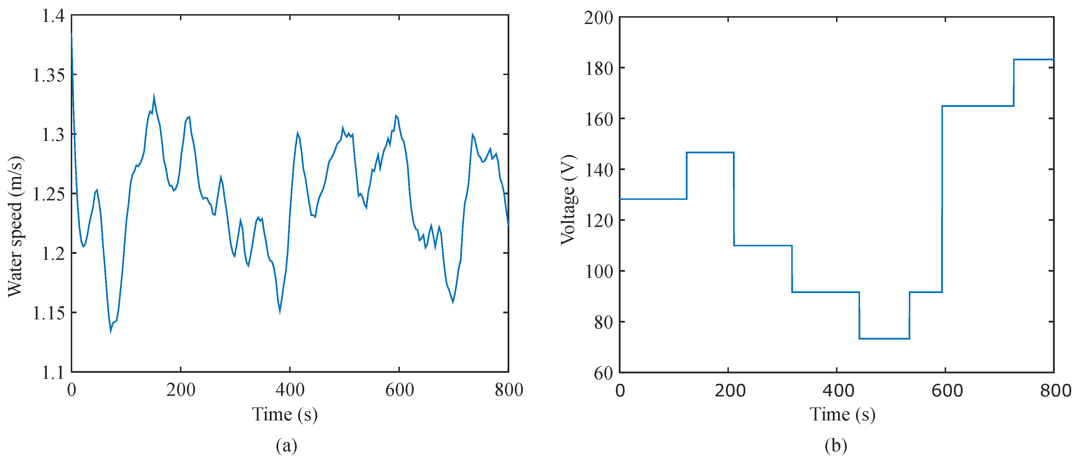
The experiment was carried out during 826 seconds of operation on 20 January 2014. The target value was changed with discrete steps and kept for a time period of at least one minute. The water speed interval of 1.1–1.25 m/s, seen in Figure 8a, and a DC bus voltage range of 75 V up to 180 V, seen in Figure 8b, covers operation in high and low λ and close to λ o p t . At the lowest DC voltage setting, in the experiment, the turbine reached a too low TSR for the turbine to absorb power, so it stopped. That water speed is far away from the calibration point used to estimate the drag losses for the simulation, see Figure 6a, where the rotational speed is overestimated by the simulation so the TSR is high enough to absorb power.
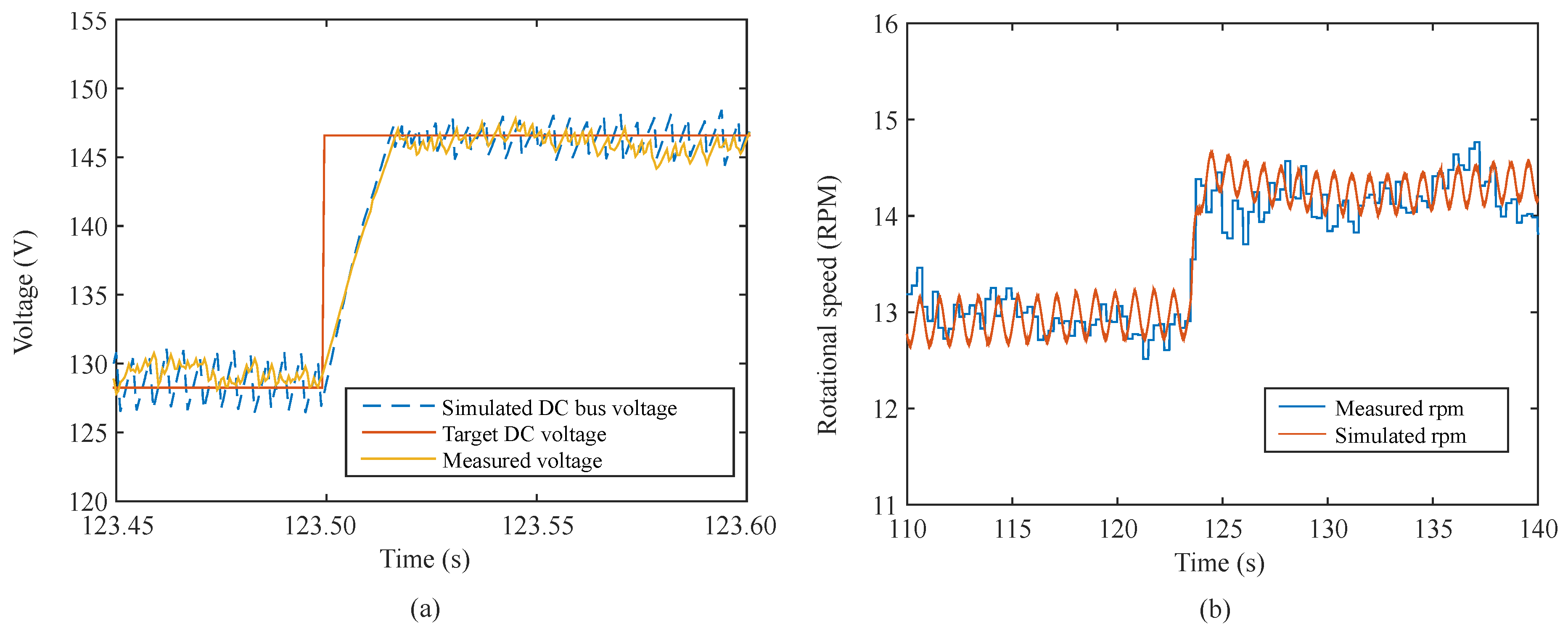
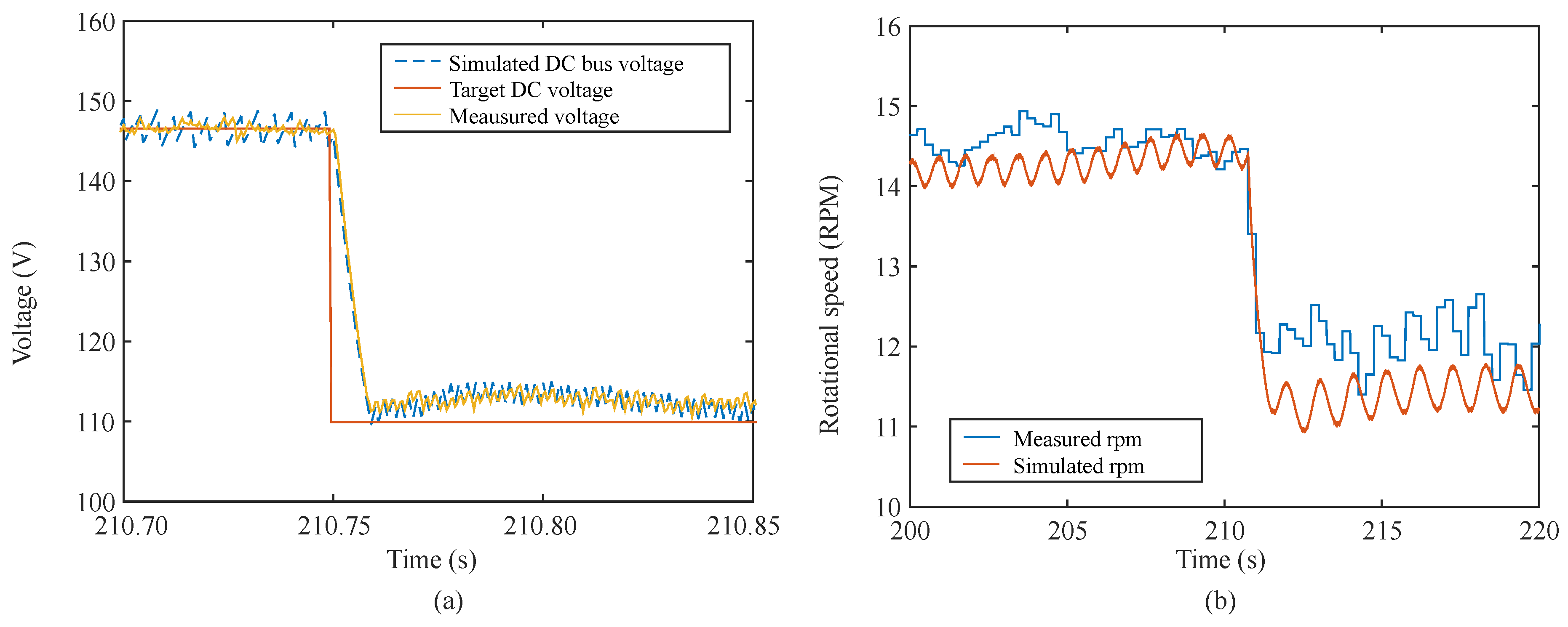
The first step response of the Target DC voltage and the rotational speed can be seen in Figure 9. λ is increased from 3.3 to 3.6 and the simulation and the experiment show good agreement. The second step response can be seen in Figure 10 where λ is decreased from 3.5 to 2.7. The simulated target DC voltage and the experiment shows good agreement, but the simulated rotational speed is lower. This is probably because the generator model overestimates the iron losses at low rotational speeds, causing more electrical power to be extracted from the generator.
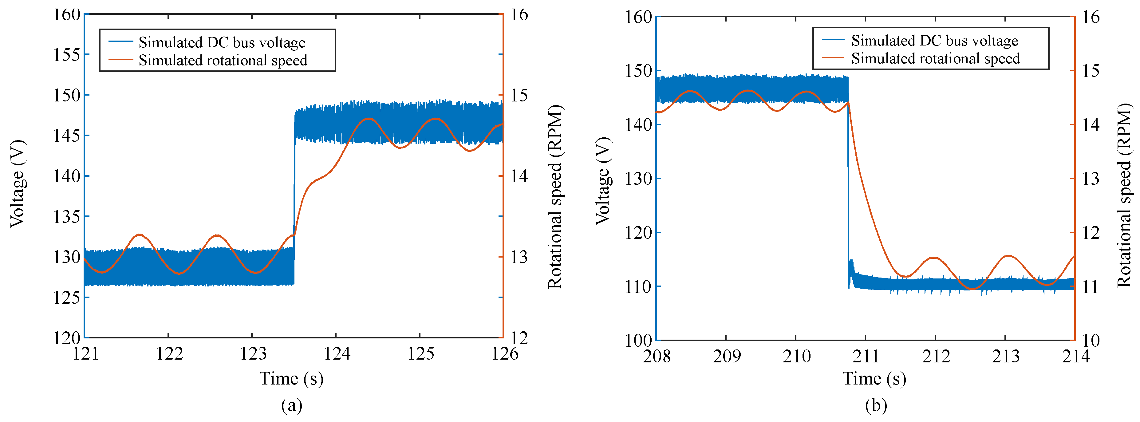
Taking a closer look at the rotational speed and the DC voltage during the two steps, in Figure 11, it can be seen that the voltage reaches the set point value much faster than the rotational speed settles at the new operating point. When a higher target voltage is set, the DC control will disconnect the load causing the generator to accelerate. During the time the load is disconnected, there is no voltage drop over the transmission cable and the full generator voltage will reach the DC load control quickly charging the capacitor. When a lower target voltage is set, the voltage drop over the transmission line will be increased.
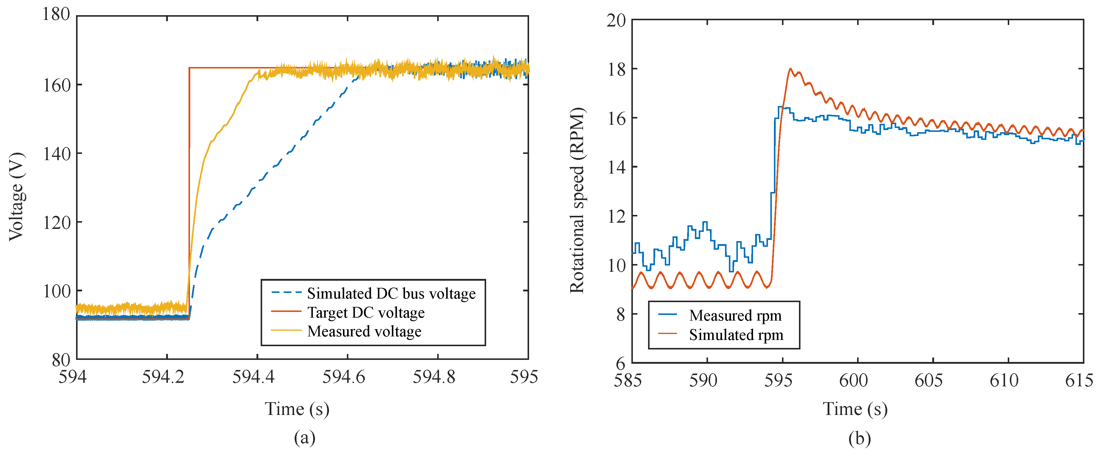
The sixth step is a big change in tip speed ratio from λ = 2.2, passing λ o p t , up to λ = 3.9, see Figure 12. Since the no-load voltage of the generator is lower than the target DC voltage set point, the DC control has to wait for the generator to accelerate in order to produce a higher voltage. Once the desired target voltage has been reached, the control system needs to brake the accelerating generator. Both in the simulation and in the experiment, there is an overshoot in rotational speed. The capability of the control system to brake the generator once it reaches the set point depends on the maximum power the load can extract. In the experiment it took less time to reach the target voltage, seen in Figure 12a, which is probably a result of the simulation predicting a lower rotational speed at the start of the step, see Figure 12b. At a lower rotational speed the turbine is operating at a lower power capture, so it needs more time to absorb the energy needed to reach the set point. Moreover, since the turbine starts at a lower rotational speed and accelerates freely, it will have a higher d ω /dt and requires more power to brake. This results in a bigger overshoot in the simulation. It has been shown in [26] that the forces on the turbine blades during runaway (overshoot related to lost control of the turbine) can be up to 2.7 times the forces during nominal operation. It is, therefore, of great importance that the control system can brake the turbine at high rotational speeds. By increasing the magnitude of the DC load the control system has a bigger load to brake the turbine with, and the overshoot could be reduced faster. However, controlling the rotational speed directly with a PI or PID regulator is a safer choice, since it can significantly reduce or completely remove the overshoot.

6. Conclusions

A simulation model that couples the electric and hydrodynamic parts of a vertical axis marine current energy converter has been validated. The hydrodynamic model is calibrated using a one parameter study of the drag losses at the rated water speed of the turbine. Compared to experimental data, the simulation predicts a higher rotational speed at low water speeds. The electrical model is calibrated by comparing the efficiency of the generator to experimental data. The model overestimated the losses at low rotational speeds. The simulated power coefficient curve of the turbine agrees well with experimental data. The model has been shown to describe the behaviour of the turbine and generator for different water flow conditions by predicting the step response of the DC bus voltage and rotational speed for a change in λ . The simulation agrees overall well with experimental data except for a big change from low to high λ where the predicted rotational speed at the start of the step is lower causing the simulation to overestimate the rise time and overshoot. The ability of the DC voltage control system to brake the turbine depends on the size of the load available. Control of the turbine at high rotational speed is of great importance to ensure a safe operation of the turbine. Controlling the rotational speed directly with a PI or PID regulator instead of the DC voltage is a safer choice since it can remove the overshoot.

Author Contributions

The main author, J.F., created the electrical simulation model and conducted the experiments. A.G. provided the vortex simulation. The work was supervised by K.T. All authors contributed to editing and reviewing of the paper.

Funding

The work was carried out using grants from StandUp, Åforsk, Vattenfall, J Gust Richert and VR.

Acknowledgments

The authors would like to thank Senad Apelfröjd and Martin Fregelius for design and construction of the DC load control and Staffan Lundin for the joint effort with the experimental work. The authors would also like to thank the previous and current members of the marine current power group for a joint effort in construction and deployment of the experimental station in Söderfors.

Conflicts of Interest

The authors declare no conflict of interest.

References

  1. Day, A.; Babarit, A.; Fontaine, A.; He, Y.P.; Kraskowski, M.; Murai, M.; Penesis, I.; Salvatore, F.; Shin, H.K. Hydrodynamic modelling of marine renewable energy devices: A state of the art review. Ocean Eng. 2015, 108, 46–69. [Google Scholar] [CrossRef] [Green Version]
  2. Khan, M.J.; Bhuyan, G.; Iqbal, M.T.; Quaicoe, J.E. Hydrokinetic energy conversion systems and assessment of horizontal and vertical axis turbines for river and tidal applications: A technology status review. Appl. Energy 2009, 86, 1823–1835. [Google Scholar] [CrossRef]
  3. Uihlein, A.; Magagna, D. Wave and tidal current energy—A review of the current state of research beyond technology. Renew. Sustain. Energy Rev. 2016, 58, 1070–1081. [Google Scholar] [CrossRef]
  4. Zhou, Z.; Scuiller, F.; Charpentier, J.F.; Benbouzid, M.; Tang, T. An up-to-date review of large marine tidal current turbine technologies. In Proceedings of the 2014 International Power Electronics and Application Conference and Exposition, Shanghai, China, 5–8 November 2014; pp. 480–484. [Google Scholar]
  5. Bahaj, A.S. Marine current energy conversion: The dawn of a new era in electricity production. Philos. Trans. A Math. Phys. Eng. Sci. 2013, 371. [Google Scholar] [CrossRef] [PubMed]
  6. Domenech, J.; Eveleigh, T.; Tanju, B. Marine hydrokinetic (MHK) systems: Using systems thinking in resource characterization and estimating costs for the practical harvest of electricity from tidal currents. Renew. Sustain. Energy Rev. 2018, 81, 723–730. [Google Scholar] [CrossRef]
  7. Paraschivoiu, I.; Allet, A. Aerodynamic analysis of the darrieus wind turbines including dynamic-stall effects. J. Propuls. Power 1988, 4, 472–477. [Google Scholar] [CrossRef]
  8. Strickland, J.H.; Webster, B.T.; Nguyen, T. A vortex model of the darrieus turbine: An analytical and experimental study. J. Fluids Eng. 1979, 101, 500–505. [Google Scholar] [CrossRef]
  9. Murray, J.; Barone, M. The development of CACTUS, a wind and marine turbine performance simulation code. In Proceedings of the 49th AIAA Aerospace Sciences Meeting including the New Horizons Forum and Aerospace Exposition, Orlando, FL, USA, 4–7 January 2011. [Google Scholar]
  10. Sorensen, J.; Shen, W.Z. Numerical modeling of wind turbine wakes. J. Fluids Eng. 2002, 124, 393–399. [Google Scholar] [CrossRef]
  11. Lundin, S.; Forslund, J.; Carpman, N.; Grabbe, M.; Yuen, K.; Apelfröjd, S.; Goude, A.; Leijon, M. The söderfors project: Experimental hydrokinetic power station deployment and first results. In Proceedings of the 10th European Wave and Tidal Energy Conference (EWTEC13), Aalborg, Denmark, 2–5 December 2013. [Google Scholar]
  12. Yuen, K.; Lundin, S.; Grabbe, M.; Lalander, E.; Goude, A.; Leijon, M. The Söderfors Project: Construction of an Experimental Hydrokinetic Power Station. In Proceedings of the 9th European Wave and Tidal Energy Conference, EWTEC11, Southampton, UK, 5–9 September 2011; pp. 1–5. [Google Scholar]
  13. Forslund, J.; Lundin, S.; Thomas, K.; Leijon, M. Experimental results of a DC bus voltage level control for a load controlled Marine Current Energy Converter. Energies 2015, 8, 4572–4586. [Google Scholar] [CrossRef]
  14. Grabbe, M.; Yuen, K.; Goude, A.; Lalander, E.; Leijon, M. Design of an experimental setup for hydro-kinetic energy conversion. Int. J. Hydropower Dams 2009, 15, 112–116. [Google Scholar]
  15. Lundin, S.; Forslund, J.; Goude, A.; Grabbe, M.; Yuen, K.; Leijon, M. Experimental demonstration of performance of a vertical axis marine current turbine in a river. J. Renew. Sustain. Energy 2016, 8, 064501. [Google Scholar] [CrossRef] [Green Version]
  16. Grabbe, M.; Yuen, K.; Apelfröjd, S.; Leijon, M. Efficiency of a directly driven generator for hydrokinetic energy conversion. Adv. Mech. Eng. 2013, 2013, 1–8. [Google Scholar] [CrossRef]
  17. Lundin, S.; Goude, A.; Leijon, M. One-dimensional modelling of marine current turbine runaway behaviour. Energies 2016, 9, 309. [Google Scholar] [CrossRef]
  18. Yuen, K.; Apelfröjd, S.; Leijon, M. Implementation of control system for hydro-kinetic energy converter. J. Control Sci. Eng. 2013, 2013, 10. [Google Scholar] [CrossRef]
  19. Cottet, G.H.; Koumoutsakos, P.D. Vortex Methods: Theory and Practice; Cambridge University Press: Cambridge, UK, 2008. [Google Scholar]
  20. Goude, A. Fluid Mechanics of Vertical Axis Turbines: Simulations and Model Development. Ph.D. Thesis, Uppsala University, Uppsala, Sweden, 2012. [Google Scholar]
  21. Dyachuk, E. Aerodynamics of Vertical Axis Wind Turbines. Development of Simulation Tools and Experiments. Ph.D. Thesis, Uppsala University, Uppsala, Sweden, 2015. [Google Scholar]
  22. Dyachuk, E.; Goude, A. Numerical validation of a vortex model against experimental data on a straight-bladed vertical axis wind turbine. Energies 2015, 8, 11800–11820. [Google Scholar] [CrossRef]
  23. Sheldahl, R.E.; Klimas, P.C. Aerodynamic Characteristics of Seven Symmetrical Airfoil Sections through 180-Degree Angle of Attack for Use in Aerodynamic Analysis of Vertical Axis Wind Turbines; Sandia National Laboratories: Albuquerque, New Mexico, 1981.
  24. Dyachuk, E.; Goude, A.; Bernhoff, H. Dynamic stall modeling for the conditions of vertical axis wind turbines. AIAA J. 2014, 52, 72–81. [Google Scholar] [CrossRef]
  25. Goude, A.; Bülow, F. Robust VAWT control system evaluation by coupled aerodynamic and electrical simulations. Renew. Energy 2013, 59, 193–201. [Google Scholar] [CrossRef]
  26. Goude, A.; Lundin, S. Forces on a marine current turbine during runaway. Int. J. Mar. Energy 2017, 19, 345–356. [Google Scholar] [CrossRef]
Figure 1. The Marine Current Energy converter rated at 7.5 kW, that can be placed on the river or sea bed. A five-bladed fixed pitch Vertical Axis Current Turbine is connected directly (no gearbox) to a Permanent Magnet Synchronous Generator. The radius, r, is 3 m and the height is 3.5 m to give a projected cross sectional area of 21 m 2 .
Energies 11 03067 g001
Figure 2. The turbine and generator are connected to the on-shore measurement and control cabin where the rectifier and DC load control is placed.
Energies 11 03067 g002
Figure 3. The Simulink model with the block Vortex simulation that imports the vortex code as a function. The DC load with rectifier block has been replaced with three resistors for the AC-load simulations.
Energies 11 03067 g003
Figure 4. The generator no load line-to-line RMS-voltage.
Energies 11 03067 g004
Figure 5. Calibration of the generator model using AC-load operation; (a) Power in the load; (b) Generator line-to-line RMS-voltage.
Energies 11 03067 g005
Figure 6. Simulated and experimentally measured free-spin operation of the turbine: (a) rotational speed vs water speed; (b) Tip-Speed-Ratio vs water speed.
Energies 11 03067 g006
Figure 7. Simulated and experimentally measured C P -curve: (a) C P t u r b i n e (including generator iron losses); (b) C P for the total system (including all mechanical and electrical losses).
Energies 11 03067 g007
Figure 8. Experimental data that was used as input for the step response simulation: (a) Measured water speed in the river; (b) Set target DC bus voltage.
Energies 11 03067 g008
Figure 9. Simulated and experimental step response of turbine operation close to λ o p t , with a step corresponding to an increase of λ : (a) DC bus voltage; (b) Rotational speed of the turbine.
Energies 11 03067 g009
Figure 10. Simulated and experimental step response of turbine operation close to λ o p t , with a step corresponding to a decrease of λ : (a) DC bus voltage; (b) Rotational speed of the turbine.
Energies 11 03067 g010
Figure 11. Simulated DC voltage and turbine rotational speed during (a) step one and (b) step two.
Energies 11 03067 g011
Figure 12. Simulated and experimental step response of turbine operation close from low to high λ : (a) DC bus voltage; (b) Rotational speed of the turbine.
Energies 11 03067 g012
Table 1. Turbine and generator specifications at rated operation.
Turbine and generator rating7.5 kW
Estimated iron, seal and frictional losses350 Nm
The Vertical Axis Current Turbine
C P m a x 0.26 at λ = 3.1
Rated water speed1.35 m/s
Rated rotational speed15 RPM
Number of blades5
Blade pitchFixed at 0 °
Blade profileNACA0021
Rotor Radius3 m
Rotor Height3.5 m
Chord length0.18 m
The Permanent Magnet Synchronous Generator
Minimum efficiency80 %
Nominal electrical frequency14 Hz
Poles112
Rated Line-to-line rms voltage138 V
Rated stator rms current31 A
Stator phase resistance0.335 Ω
Armature inductance3.5 mH
Table 2. Rectifier and DC load parameters in Simulink.
The PMSG Generator block
Flux linkage1.28 Vs
Estimated moment of inertia3000 kgm 2
DC load parameters
Rectifier on-resistance1 m Ω
Rectifier forward voltage drop0 V
IGBT on-resistance0.1 m Ω
IGBT forward voltage drop1 V
Snubber resistance47 k Ω
Snubber capacitance470 nF