1. Introduction
During the last decade, the use of renewable energy sources (mainly wind and solar) have gained increasing attention for several reasons such as the reduction of pollution caused by traditional sources of energy (mainly fossil fuels) and the removal of dependence on exhausted resources. Nowadays, the scientific community is focusing on wave energy due to its potential for supplying a considerable part of the electricity demand in some countries [
1,
2,
3,
4,
5].
The wind over the ocean surface is a major cause of the waves. In many areas of the world, the wind generates continuous waves that may be converted into power in a consistent way. Following diverse approaches, several devices are being designed to harness the massive energy of the waves, either by extracting energy from the waves motion over the ocean surface or by benefiting from the pressure fluctuations below the surface [
6,
7,
8]. In this work, a Wells turbine-based oscillating water column (OWC) device is used for converting the energy of the waves into mechanical energy [
9]. The obtained mechanical energy depends on the wave characteristics—mainly height, speed, wavelength, and water density [
10,
11].
The doubly fed induction generator (DFIG) is used at many renewable power generation plants (e.g., wind turbines and wave energy plants) since they are able to adapt to sudden changes [
12,
13,
14,
15,
16]. In these machines, the stator is connected directly to the grid, but the rotor is connected to the grid by means of a variable frequency converter (VFC). This configuration benefits from the fact that the VFC only manages a fraction, around (25–30%), of the nominal power for controlling the generator. Typically, one voltage source of the VFC is located at the grid side, the so-called grid-side converter (GSC), another is located at the rotor side, the so-called rotor-side converter (RSC), and a capacitor is used to connect back to back both converters [
17,
18,
19].
The most frequent strategy to control these systems is a combination of vector control with cascaded PI control for current and power [
20]. However, the nonlinear nature of these systems and their uncertainties suggest that the use of a more robust controller could improve the system performance.
One alternative is considering the sliding mode control (SMC) technique. SMC has proven to be suitable at systems in which a precise model is known. In addition, it reduces the sensitivity to variation parameters and rejects external disturbances [
21,
22]. During the last decade, the SMC techniques have been applied to control several types of electrical devices obtaining good results [
23,
24,
25,
26].
Traditionally, in OWC systems, the rotational speed of the turbine is adjusted taking into account the maximum pneumatic energy level available to the turbine [
27,
28,
29]. However, in the control scheme proposed in this work, a new reference for the turbine speed, based on the airflow velocity, is proposed.
This work presents an SMC scheme aimed at improving the generation of power in an OWC system that incorporates a Wells turbine in order to transform the pneumatic energy into mechanical energy. The proposed approach is aimed at tracking the speed of the turbine in order to maximize power extraction. SMC theory and DFIG rotor current regulation were used to control the turbine speed. By regulating the speed of the turbine, the flow coefficients are optimized in order to maximize power generation even when there are uncertainties in the model or variations in the wave power.
The design of the traditional SMC scheme requires calculating an upper bound for the system uncertainties since the value of the sliding gain used must be higher. This value is directly related to the control effort, so a high sliding gain value implies a high control effort possibly causing the chattering problem. This problem arises because the sliding control signal is discontinuous across the sliding surfaces, so this kind of signal involves high control activity and may also excite the high frequency dynamic of the system. Therefore, the system uncertainties should be bounded accurately. In order to avoid this problem, the proposed control scheme includes an adaptive law to calculate the sliding gain.
The closed loop stability of the proposed control scheme was proven using the Lyapunov stability theory. The performance of this control scheme is validated by means of the Matlab/Simulink software. The conditions of operation, as well as the simulation results, are discussed in detail.
This paper is organized as follows:
Section 2 presents a model for the plant used, the OWC.
Section 3 introduces the design of the adaptive sliding mode control scheme.
Section 4 presents the simulation results obtained.
Section 5 presents the conclusions.
2. OWC Plant Model
In this work, an OWC system with a Wells turbine and a DFIG is considered.
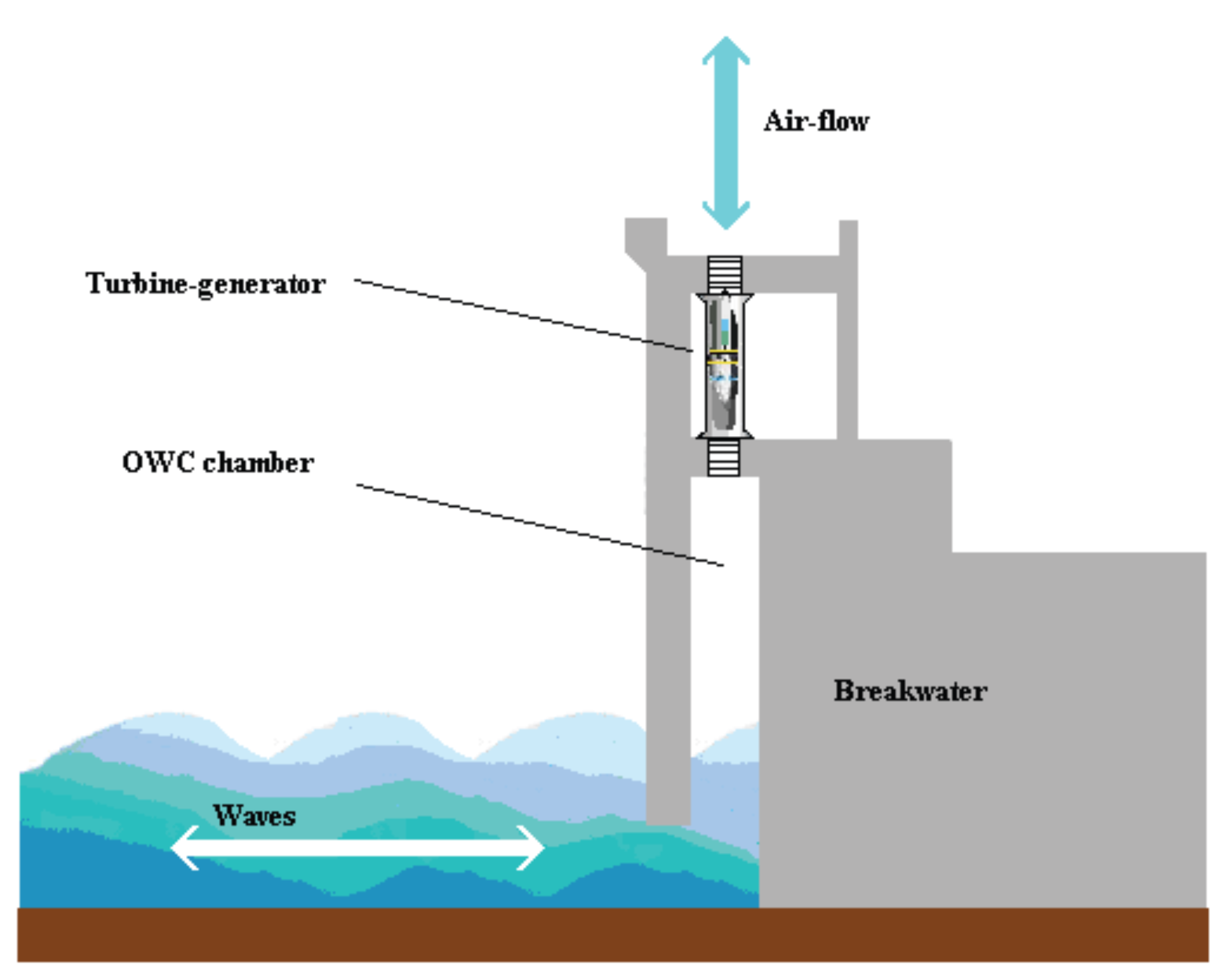
Figure 1 shows how the OWC device uses the hydraulic energy of the waves to create an oscillating air flow that moves the turbine.
In an OWC system, the chamber collects the flow of air generated by the ocean waves. At the top of this chamber, there is a turbine, which is connected to a generator by means of a gear box. The airflow in the chamber is bidirectional since it depends on whether the waves hit or reflect. However, the Wells turbine rotates always in one direction, independently of the air flow direction, which has proven very useful to be used in maritime energy. This turbine was designed by Prof. Alan Arthur Wells of Queen’s University Belfast at the end of the 1970s.
The power that can be extracted from the airflow in the chamber of the OWC is determined by [
30]
where
is the speed of the airflow,
is the pressure drop at the turbine, and
is the area of the turbine duct.
It should be noted that the equations for the OWC system are quite similar to the equations obtained for the wind turbine systems. The term , that also appears in the wind turbines, takes into account the kinetic energy. The other term takes into account the air pressure in the chamber and appears owing to an OWC chamber.
In this work, the turbogenerator module of the OWC is used with a Wells turbine, which is connected to a DFIG by means of a gearbox.
The DFIG is an induction machine typically used in renewable electric generation devices, such as wind turbines. A VFC is used to connect the rotor circuit of the DFIG to the grid, whereas the stator is directly connected. In order to deliver active power to the grid, regarding the frequency and voltage stability requirements of the grid, the flow between rotor and grid must be controlled in magnitude and direction. However, these machines are designed to operate at an extended range of rotational conditions, from subsynchronous to supersynchronous speed.
The use of this configuration allows that the power electronic converters deliver electrical power to the grid by managing a fraction of the nominal power, typically between 25 and 30%. The power generated at the stator goes directly to the grid, whereas the power obtained at the rotor is delivered by means of a VFC. As a result, the power converters needed can be relatively smaller when compared with other configurations. Moreover, this configuration provides additional benefits, such as improving the performance and reducing the cost of the equipment.
Typically, at this type of systems an inertia wheel drive is included for smoothing the curve of the output power delivered by the generator. This component facilitates the application of SMC schemes at these systems, since some phenomena that may appear, such as the chattering problem, can be absorbed by the inertia wheel.
This work assumes the use of Wells turbines for extracting the energy of the airflow. These turbines are designed to always turn in the same direction, independently of the sense of the airflow that moves the turbine, providing a robust behavior. The key at these turbines is the design of the blade, which is simple and symmetrical. The mathematical model for these turbines is given by the following equations [
31]:
where
is the generated torque at the Wells turbine,
is the flow coefficient,
is the power coefficient,
is the torque coefficient,
is a turbine specific constant,
is the radius or the turbine,
is the speed of the airflow,
is the rotational speed of the turbine,
and
are constants related to the blades—respectively, the blade height and the blade chord length—
n is the number of blades,
is the flow rate,
is the cross-sectional area of the turbine, and
is the efficiency of the turbine.
According to the equations of the presented model, both the torque and power generated by a Wells turbine can be obtained from the torque and power coefficients, respectively. The characteristic curves of the Wells turbine show the relationship between the torque and power coefficients versus the flow coefficient.
The performance of a Wells turbine decreases severely when the speed of the airflow goes beyond a critical value, which depends on the rotational speed of the turbine [
31]. This phenomenon is known as stalling, since the Wells turbine stalls when the relative angle formed by the axial speed of the input airflow and the tangential velocity of the turbine surpasses a specific value. This value is typically close to
.
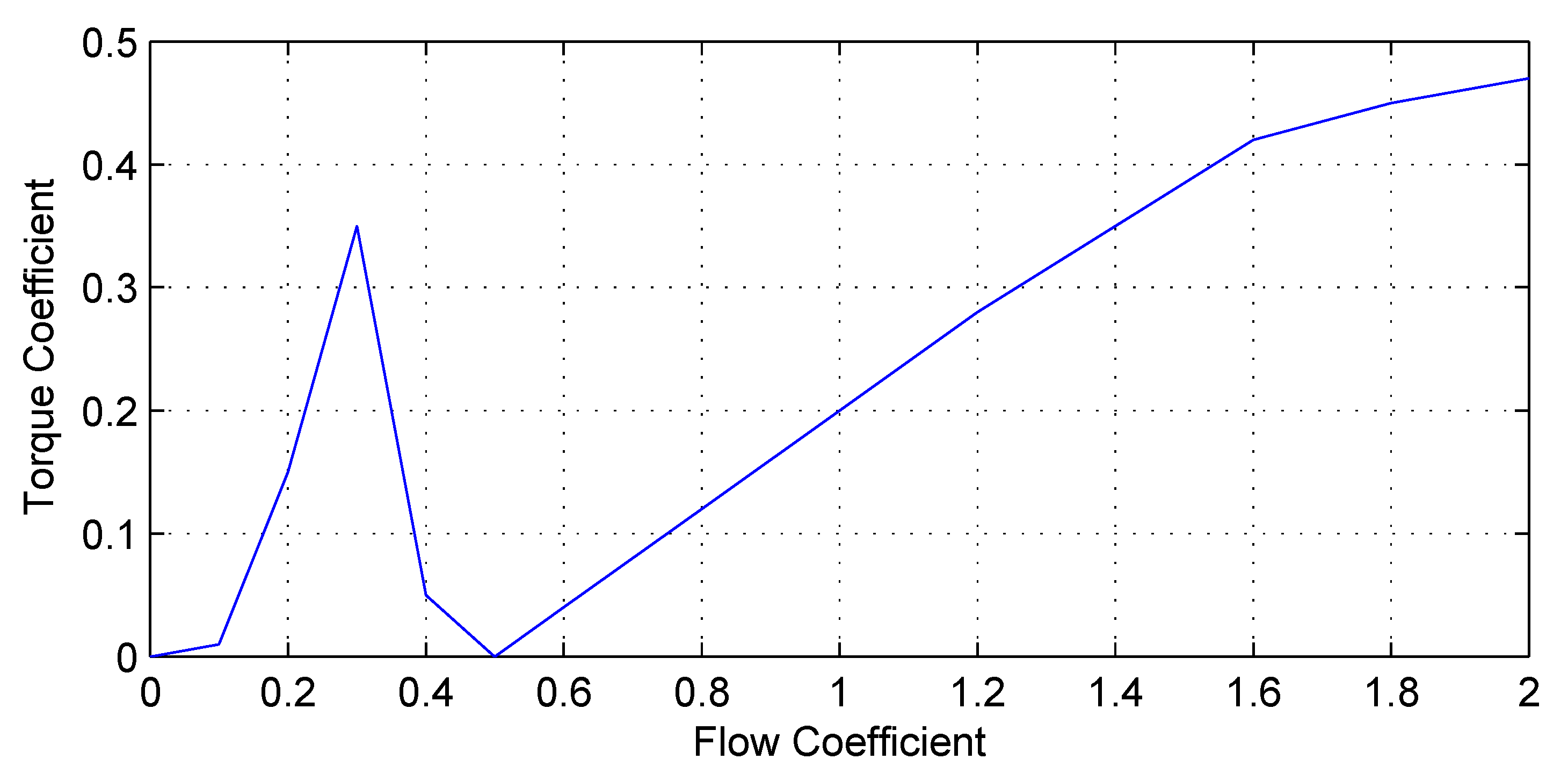
Figure 2 depicts the torque versus flow coefficients (
) for a specific Wells turbine. It can be seen in the figure that the value of
, the torque coefficient of the turbine, decreases severely when the turbine stalls (due to the stalling phenomenon). Even though this figure was obtained for a specific turbine and in general the behavior depends on some constructive parameters, the characteristic curves for diverse turbines present similar features.
For this specific turbine,
Figure 2 illustrates that, when the flow coefficient reaches the value of
, stalling occurs. As remarked above, the value for the flow coefficient differs depending on the characteristic curve for a specific Wells turbine. It may be concluded from the picture that a value for the flow coefficient of around
is a good alternative. On one side, this value avoids the phenomenon of stalling and maximizes the value for torque
.
Since the movement of the airflow is caused by the ocean waves, which have an oscillatory nature, the value of the flow coefficient is consequently oscillating between zero and a positive value. Thus, the optimal zone of operation for the turbine is located from zero to the point at which the stalling phenomenon appears.
Taking into account the previous considerations and using Equation (6), the reference value for the turbine speed that maximizes the power extraction from the ocean waves can be obtained from
Therefore, the flux coefficient in the Wells turbine may be optimized using an adequate turbine speed regulation that follows the reference value given by Equation (
9).
3. Adaptive Sliding Mode Control Scheme for an OWC
In a DFIG-based OWC wave energy converter, the extracted power may be maximized by regulating the rotational speed of the Wells turbine. Thus, the value for the flux coefficient can be optimized while avoiding the stalling phenomenon. This objective may be achieved by means of an adaptive SMC scheme that controls the rotational velocity at the DFIG, which may be achieved using the quadrature component of the current at the rotor.
In the discussion about the model of the OWC system, it was pointed out that the shaft speed for the turbogenerator should be adjusted below the stalling phenomenon. Thus, the flow coefficient value provides an optimum value that extracts the maximum power from the sea waves. This would produce the maximum value for the torque coefficient while avoiding stalling.
For a given pressure drop input , there is only a unique value for the speed reference that satisfies the condition for finding the optimum flow coefficient that maximizes the extraction of energy from the waves. This value can be obtained from the characteristic curve supplied by the manufacturer of the turbine. Obviously, this procedure is valid for any Wells turbine since they always present a similar stalling phenomenon.
This approach for designing the control scheme is quite similar to other well-established DFIG-based applications. The control strategies aimed at extracting the maximum power in wind turbines follow a similar approach. In such applications, the controller should follow the tracking reference in order to control the speed of the turbine. The tracking reference depends on the maximum variation of the power with the angular velocity for the DFIG. Obviously, the reference should differ since the aerodynamic characteristics for every turbine are also different, provided that different characteristic curves form the power coefficient versus the tip speed ratio [
32].
The design of the adaptive SMC is based on the dynamics of the turbogenerator. Consequently, a dynamic model for the turbogenerator must be obtained. The dynamics of the turbogenerator involves both mechanical and electrical areas.
The following equation models the dynamics for the mechanical part of the turbogenerator:
where
is the turbine torque, generated by the airflow induced by the waves,
B is the viscosity coefficient,
is the torque generated by the generator,
J is the moment of inertia,
w is the rotational velocity for the turbine, and the gear ratio
yields the ratio between the rotational speeds for the turbine,
w, and the generator rotor,
.
The use of vector control techniques simplifies the DFIG model, since all expressions are referred to the stator flux reference frame. The d-axis is aligned with the stator flux linkage vector
; thus,
=
and
= 0. The following expressions are thus obtained [
33]:
where
and
are the q-d components for the current at the stator,
and
are the
q-
d components for the current at the rotor,
,
, and
are the stator inductance, rotor inductance, and mutual inductances, respectively,
is the current for magnetizing the stator,
is the angular velocity of the synchronous reference,
is the slip frequency,
is the velocity for the rotor at the generator,
and
are the q-d components of the voltage at the rotor,
and
p is the pole numbers.
The current for magnetizing the stator (
) may be taken as a constant value due to that the stator resistance has small influence and the stator is directly connected to the grid [
17]. Accordingly, the electromagnetic torque can be calculated as follows:
where the torque constant value
is calculated below:
Substituting Equation (
17) into Equation (
10), a new expression for the dynamics is obtained. This expression includes the uncertainty terms:
where
,
,
, and the terms
,
, and
represent the uncertainties of the terms
,
, and
f, respectively.
The dynamic Equation (
19) can then be rewritten as
where all terms related to the uncertainty have been represented as
:
Considering the properties of the SMC scheme, the proposed adaptive sliding mode compensates the uncertainties of the system.
The tracking error for the rotational velocity is defined with the following expression:
where
is the reference for the turbine speed that maximizes power extraction from ocean waves.
The time derivative of the previous expression is
An adaptive SMC scheme aimed at tracking the reference for the turbine velocity is then proposed. This controller is able to extract the maximum power from the waves in spite of the uncertainties at the plant.
The sliding variable
may be set as
where
k represents a positive constant value for the gain.
The sliding surface proposed is as follows:
As a consequence, the sliding mode controller for the velocity is obtained:
where
is the estimated switching gain,
k is the gain defined previously,
S is the sliding variable defined in Equation (
24),
is the signum function, and
is a positive constant.
It should be noted that the control Equation (
26) includes some terms that compensate the known dynamics of the system (
) and other terms that compensate the uncertainties (
).
The updating law for the switching gain
is defined as
where the adaptation speed for the switching gain can be selected using the positive parameter
.
The following condition should be fulfilled to obtain the tracking signal for the speed reference:
There are a finite and positive switching gain,
, which verifies the following:
where
.
Note that further knowledge is not required for the upper bounds for the uncertainties. This assumption implies that the system uncertainties are bounded.
The Lyapunov stability theory will be used for ensuring the closed loop stability of the proposed control scheme for the wave power plant that moves the DFIG. This scheme implements the control law of Equation (
26) using the value of Equation (
27) for obtaining the switching gain. The dynamics for the DFIG is provided by (
19).
Proof. The Lyapunov function candidate may be declared as
where
and
is the previously defined sliding variable. □
The time derivative of the previous Lyapunov function candidate is
It should be indicated that in this proof the condition
and the Equations (
23), (
24), (
26), and (
27) have been used.
Based on the previous results, it can be stated that
is a negative definite function. Hence,
is a positive definite function, and, when
tends to infinity,
tends to infinity. Consequently, it can be concluded that the equilibrium at the origin
is globally asymptotically stable by means of the stability theory of Lyapunov. Accordingly, when
time tends to infinity,
goes to zero. This means that the trajectories that start out of the sliding surface will reach it and must remain in this sliding surface. This behavior is commonly called
sliding mode [
34].
When the sliding surface, Equation (
25), is reached, both
and
decrease to zero. At that time, the dynamic behavior of this system tracking problem can be represented by the following equation:
Considering that k is a positive constant it can be concluded that converges exponentially to zero.
Therefore, the presented sliding mode control scheme can be employed in order to regulate the speed of the Wells turbine for wave power generation plants. This control scheme has been designed in order to extract the maximum power from the ocean waves under some uncertainties in the parameters of the system and under unmodeled dynamics.
4. Simulation Results
In this section, the performance of the proposed adaptive SMC scheme designed to regulate the turbine speed in an OWC wave power generator system is analyzed by means of some simulation examples. The goal of this control scheme is to obtain the maximum electrical power using the mechanical power extracted from the waves. For that, the optimal turbine speed command (that yields the maximum mechanical power) should be tracked by the turbine speed. In the following simulations, the proposed optimum tracking control scheme (that tracks the oscillating dynamics of the air flow in order to optimize the flow coefficient value) is compared with a control scheme without this optimum tracking control (the controller does not track the air flow variations in order to optimize the flow coefficient value).
Figure 3 shows the block diagram of the proposed adaptive SMC scheme designed to regulate the speed of the turbine. In this figure, the block “Reference Generator” gives the reference for the turbine speed in order to obtain the optimum flow coefficient and accordingly the maximum power. This block is implemented by Equation (
9). The block “SMC” is the proposed adaptive SMC that provides the rotor current control designed to track the reference speed. This block is implemented by Equation (
26).
The Wells turbine used in the simulations has the following parameters:
(number of blades);
Kg m (turbine torque coefficient);
m (turbine radius);
m (turbine cross-sectional area);
m (turbine blade height);
m (turbine blade chord length).
The DFIG has the following parameters that are given in the per unit system:
27 kW (nominal power);
(number of poles);
pu (stator inductance);
pu (stator resistance);
pu (rotor inductance);
pu (rotor resistance);
pu (mutual inductance);
s (inertia constant);
pu (friction factor).
Simulations were developed with the Matlab/Simulink software and the SimPowerSystems library [
35].
In this control scheme validation, an uncertainty of in the parameters of the system was considered. However, the simulation results show that the proposed control approach is able to cope with this uncertainty without deteriorating the system performance.
The next values for the parameters of the controller are selected: and . These values have been tuned experimentally considering their influence in the performance of the proposed control scheme. In this sense, the following rules should be considered in the selection of these parameters. An increase in the parameter k yields a decrease in the speed error convergence time. Unfortunately, this also increases the initial values of the control signal, because in the initial state the error is high, and this is undesirable in real applications. On the other hand, an increase in the parameter provides a faster adaptation dynamic for the sliding gain. Unfortunately, this also increments the final value of the sliding gain, which is not desirable in real applications.
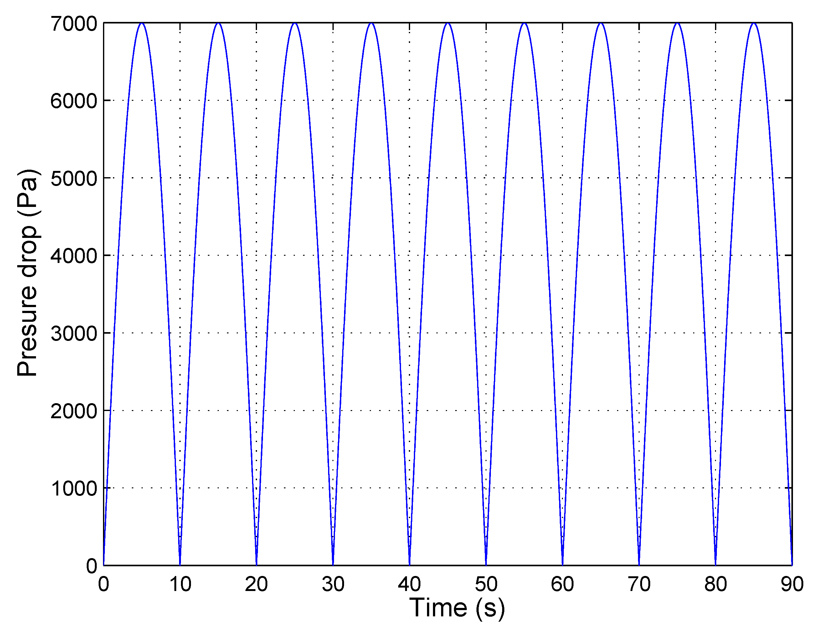
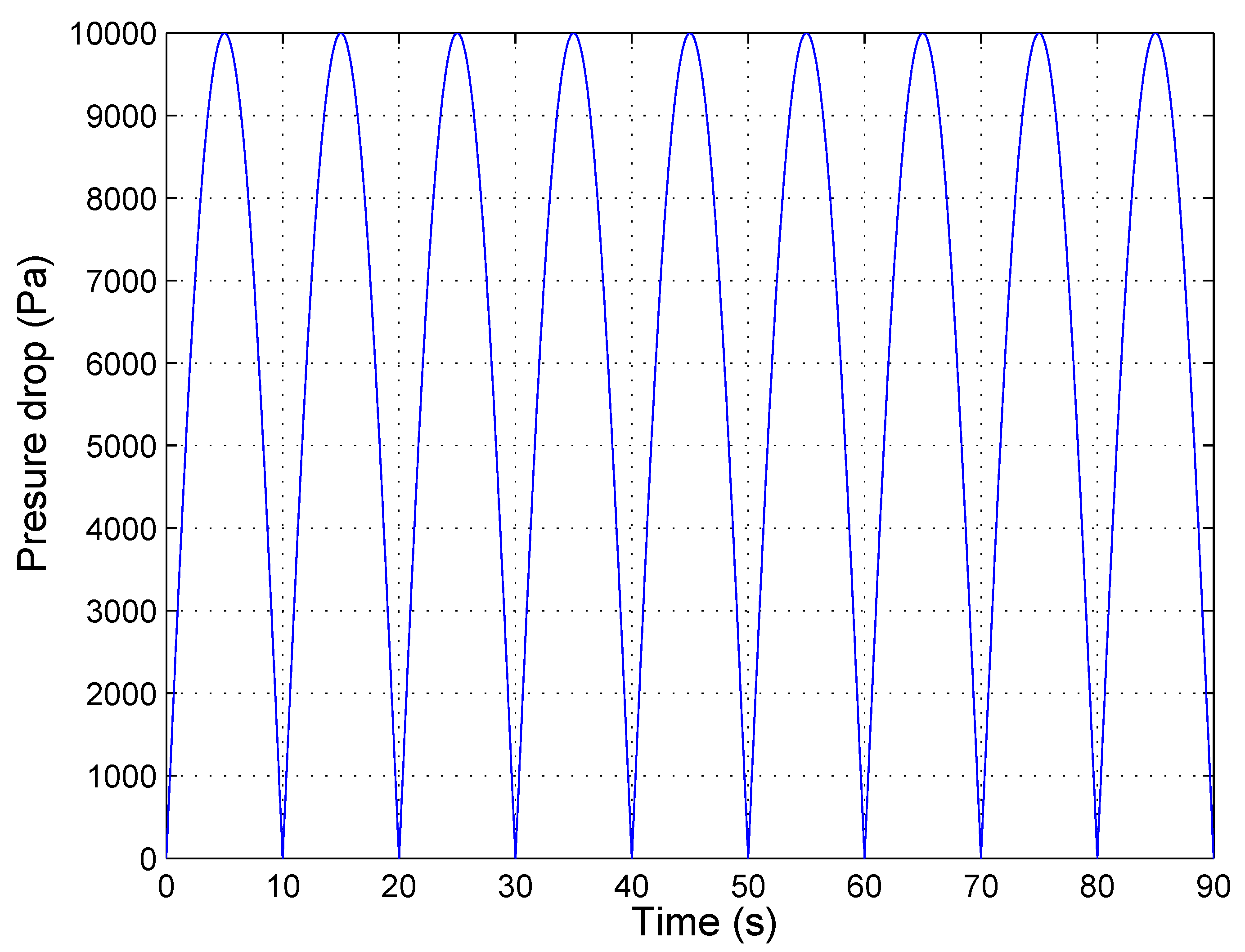
In the first simulation example, it is considered that the ocean waves produce an oscillation in the pressure drop given by
(Pa). This pressure variation is shown in
Figure 4. This value for the pressure drop is considered low because it provides a flow coefficient values below the stalling behavior.
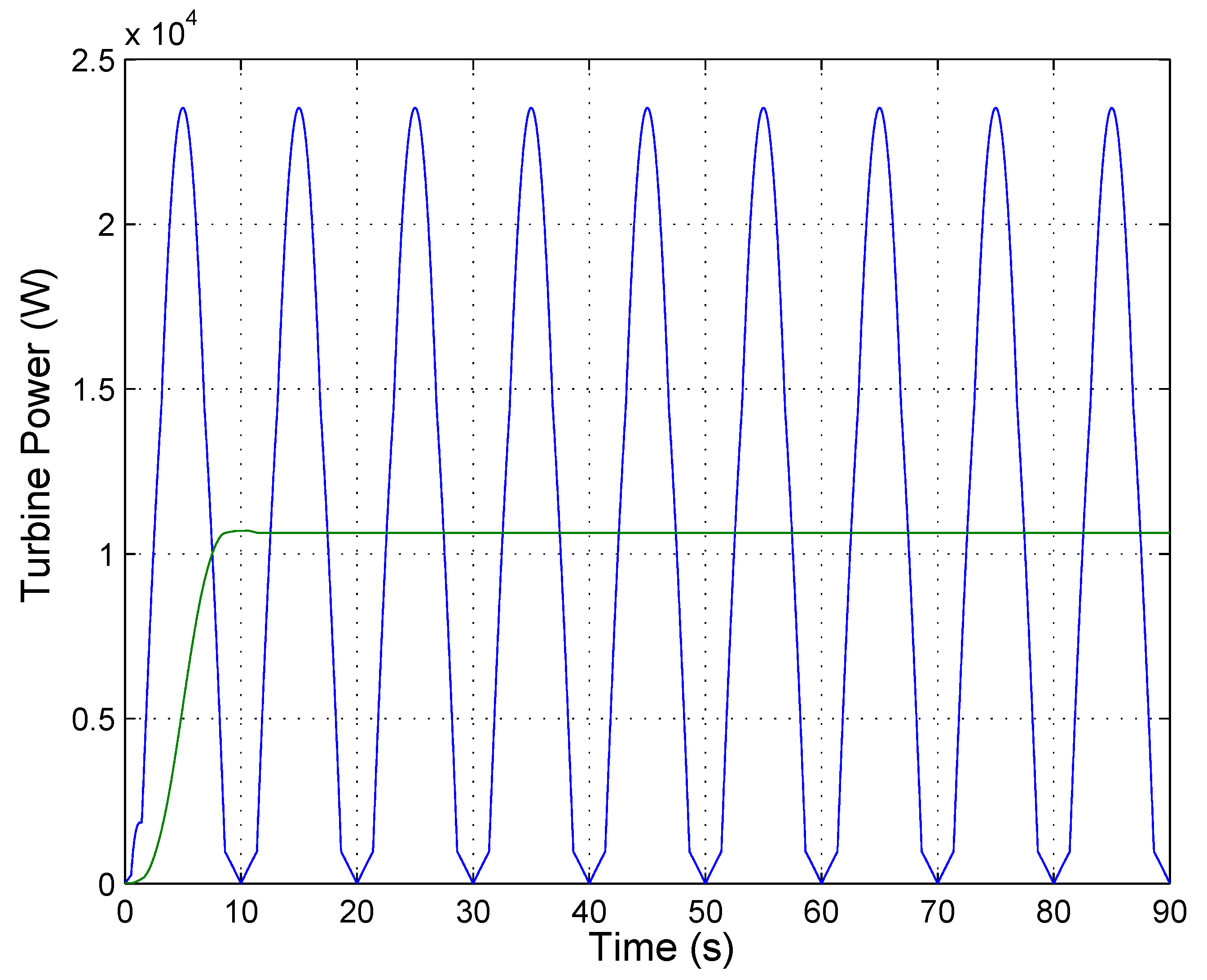
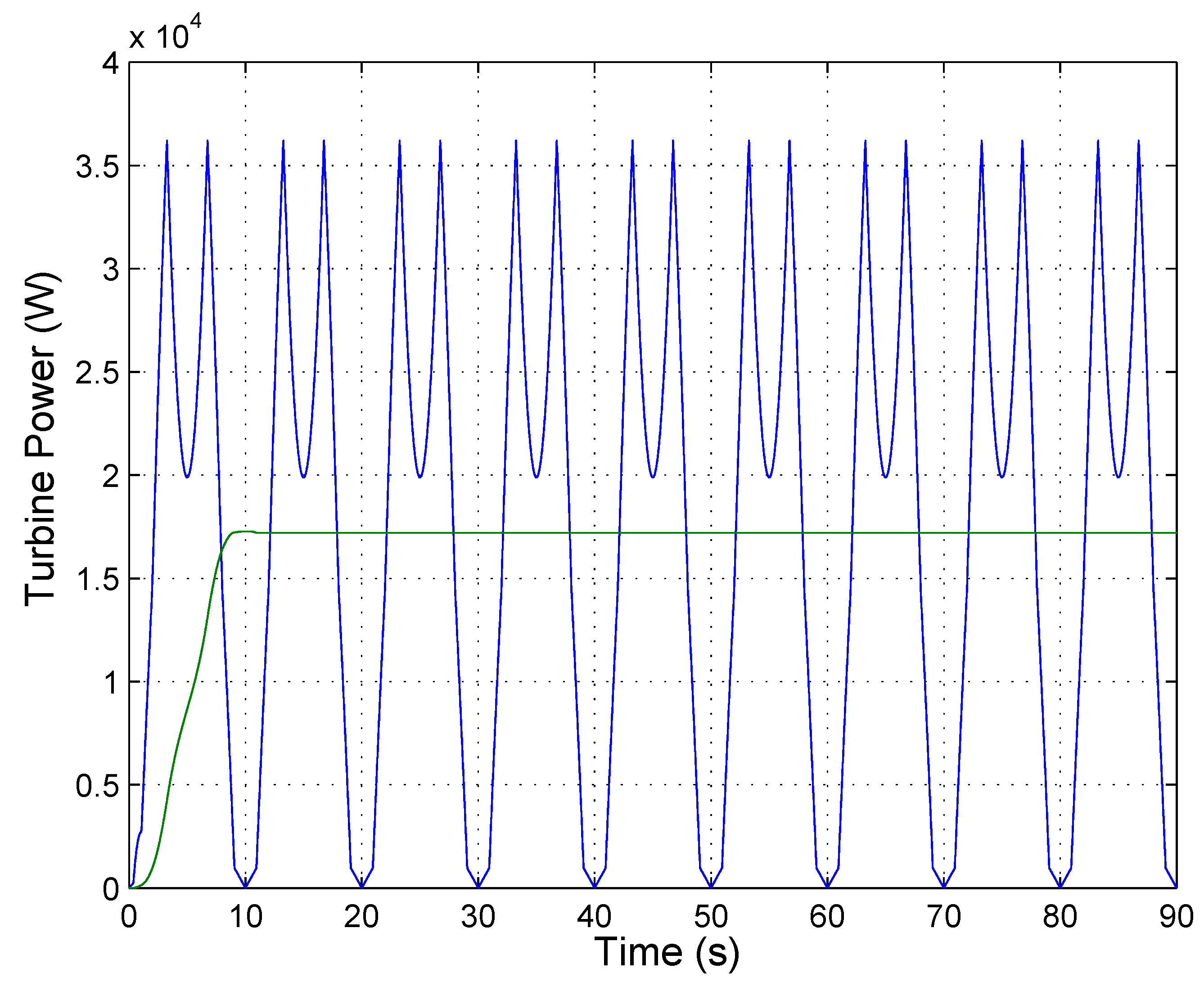
Figure 5 shows the turbine mechanical power produced by this pressure drop using the proposed adaptive sliding mode control in order to track the turbine speed command that provides the optimum flow coefficient value and hence the maximum power extraction. As can be observed, the average value of the mechanical power produced is 14.2 kW (green line).
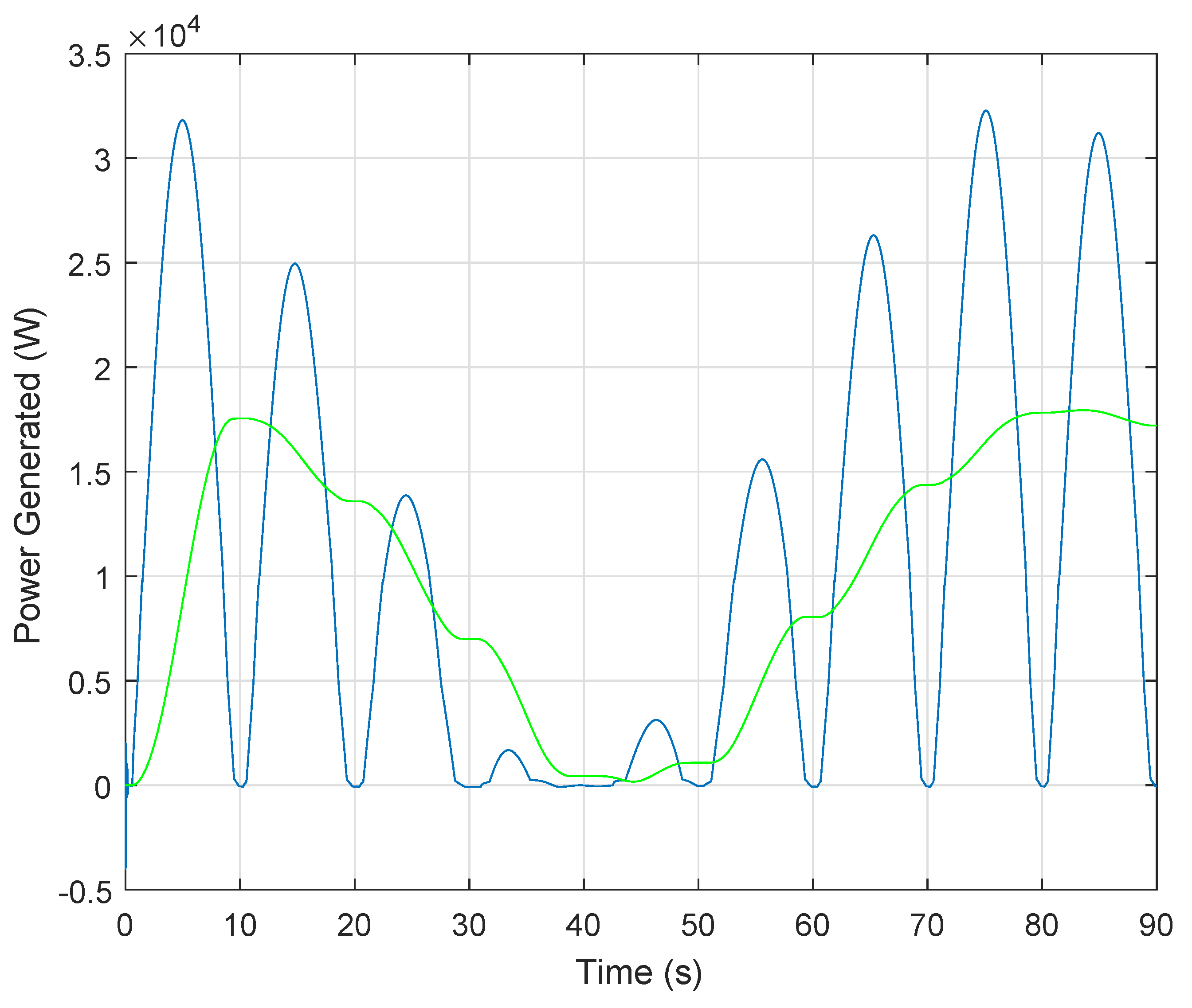
Figure 6 shows the electrical power generated whose average value is 10.7 kW (green line).
Figure 7 shows the generator speed whose value is regulated using the proposed adaptive SMC that has been designed in order to optimize the flow coefficient and hence the mechanical power extraction from the Wells turbine system.
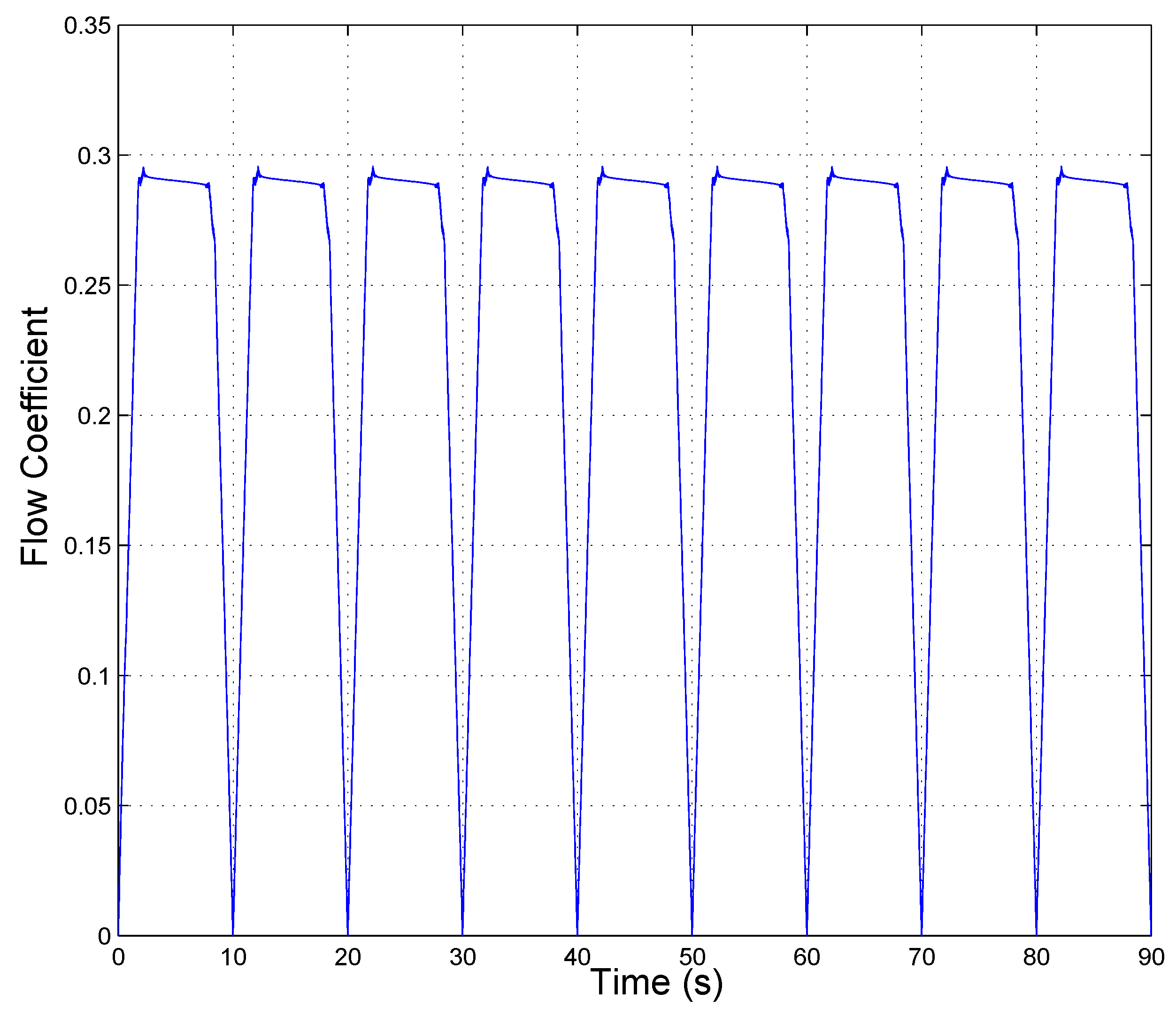
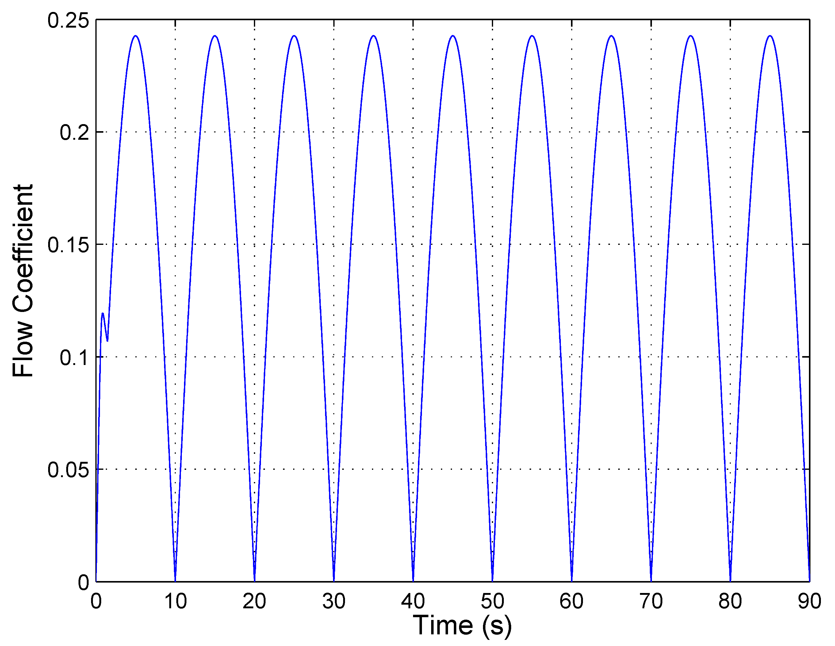
Figure 8 shows the flow coefficient for this SMC. This figure shows that the speed regulation of the Wells turbine improves the flow coefficient values in order to maximize the mechanical power generation, because the flow coefficient is maintained, almost all of the time, close to the optimum value,
, which provides the maximum torque coefficient. It should be noted that the flow coefficient always have to decay to zero due to the oscillatory dynamics of the pressure drop that also decays to zero. However, the SMC tracking control increments the time in which the flow coefficient is maintained close to the optimum value.
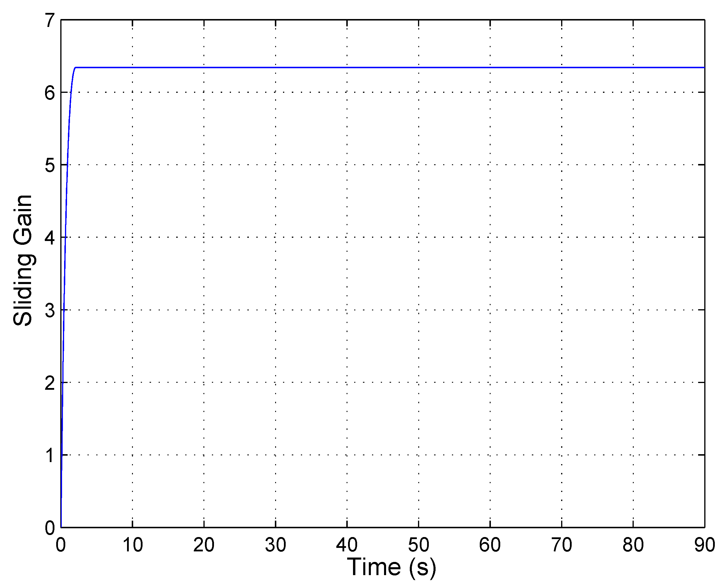
Figure 9 shows the time evolution of the sliding gain value, which is adapted online in order to overcome the system uncertainties. As can be seen in this figure, the sliding gain value starts from zero increasing its value until the sliding gain is high enough to compensate the uncertainties of the system.
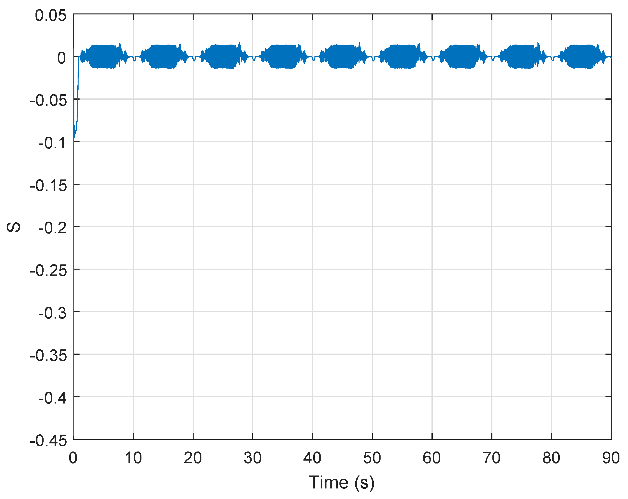
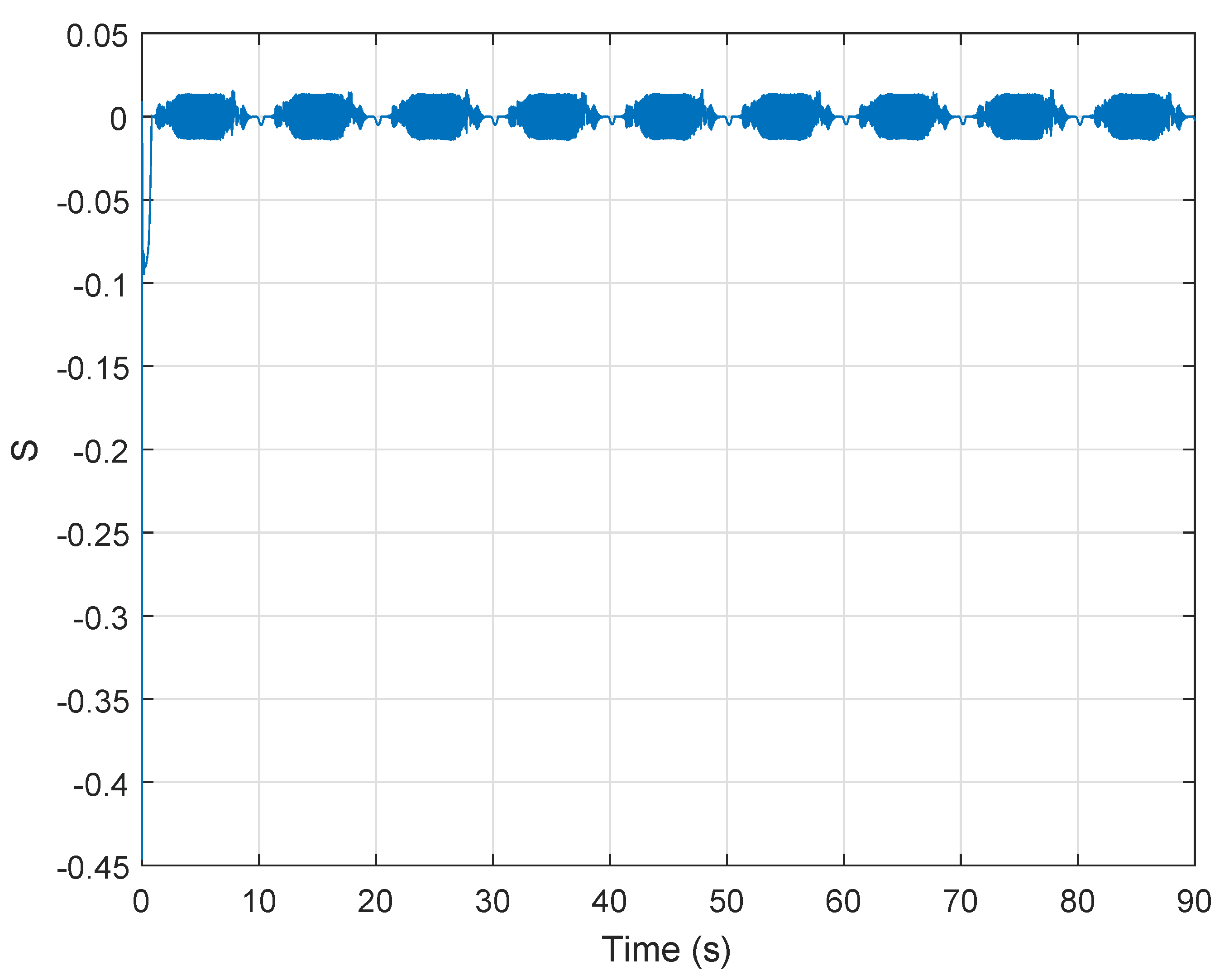
Figure 10 shows the sliding variable and
Figure 11 shows the control signal. As can be observed, the control signal presents the chattering phenomenon that, as is well known, usually appears in the SMC schemes. However, this chattering will be filtered by the mechanical system inertia and it does not present a big problem in this case. Nevertheless, this chattering can be reduced by replacing the sing function with the saturation function [
18].
Figure 12 shows the turbine mechanical power produced by this pressure drop for this system without optimum tracking control; that is, in this case the turbine speed does not follow the reference value that provides the optimum flow coefficient. The average value of the mechanical power produced in this case is 10.8 kW (green line).
Figure 13 shows the electrical power generated whose average value is 8.2 kW (green line).
Figure 14 shows the flow coefficient obtained for this system without optimum tracking control. In this figure, it can be observed that the flow coefficient is not optimized in order to increment the mechanical power generation, and the flow coefficient is therefore not maintained close to the optimum value
. In this case, without optimum tracking control, the dynamics of the flow coefficient follows the oscillatory dynamics of the pressure drop.
Therefore, comparing
Figure 6 and
Figure 13, it can be observed that the electrical power generated by an OWC-based wave power generation plat can be improved by controlling the generator speed in order to obtain the optimum flow coefficient value for the Wells turbine that produces the maximum wave energy extraction.
In the second simulation example, it is considered that the ocean waves produce an oscillation in the pressure drop given by
(Pa). This pressure variation is shown in
Figure 15. This value for the pressure drop is considered high because it provides a flow coefficient that reaches the stalling behavior.
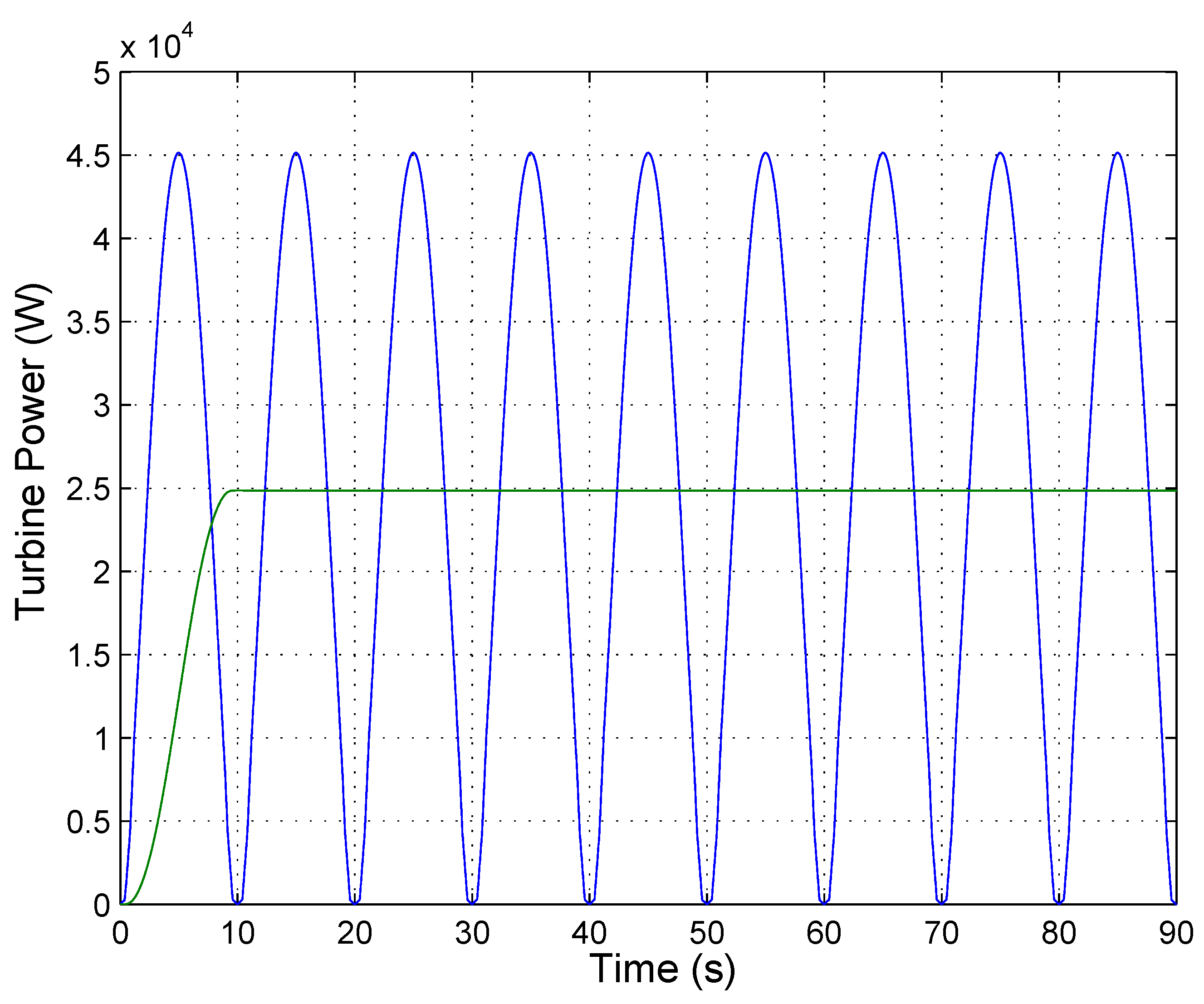
Figure 16 shows the turbine mechanical power produced by this pressure drop using this adaptive SMC. The average value of the mechanical power produced is 24.9 kW (green line).
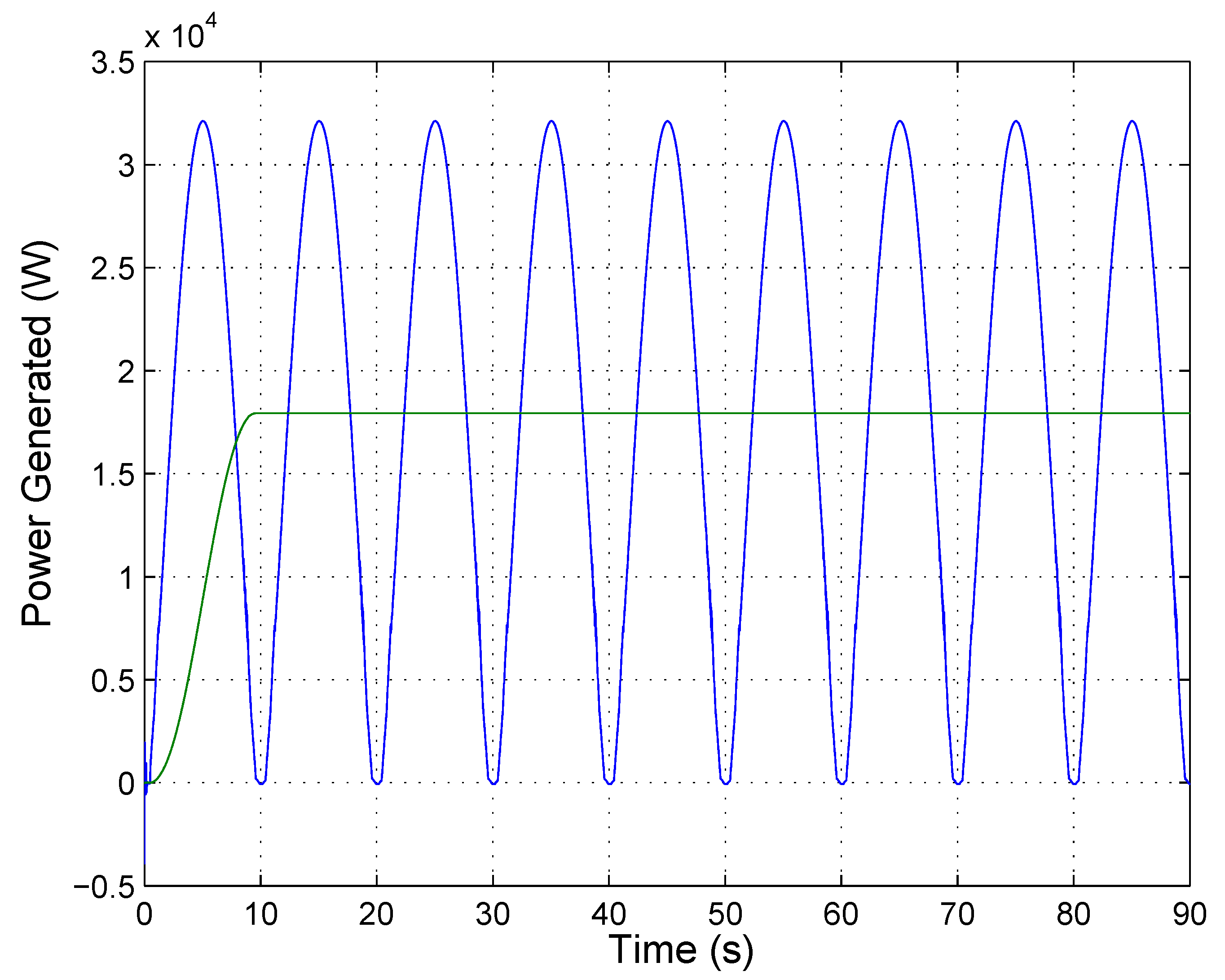
Figure 17 shows the electrical power generated whose average value is 18.3 kW (green line).
Figure 18 shows the generator speed whose value is regulated by this adaptive sliding mode control in order to optimize the mechanical power extraction from the Wells turbine system.
Figure 19 shows the flow coefficient for the SMC case where the flow coefficient is maintained close to the optimum value. This figure shows that the speed regulation of the Wells turbine improves the flow coefficient values and hence optimizes the mechanical power generation. Moreover, the proposed speed regulation also avoids the stalling behavior that usually happens in the Wells turbine because the flow coefficient is maintained below the critical value
.
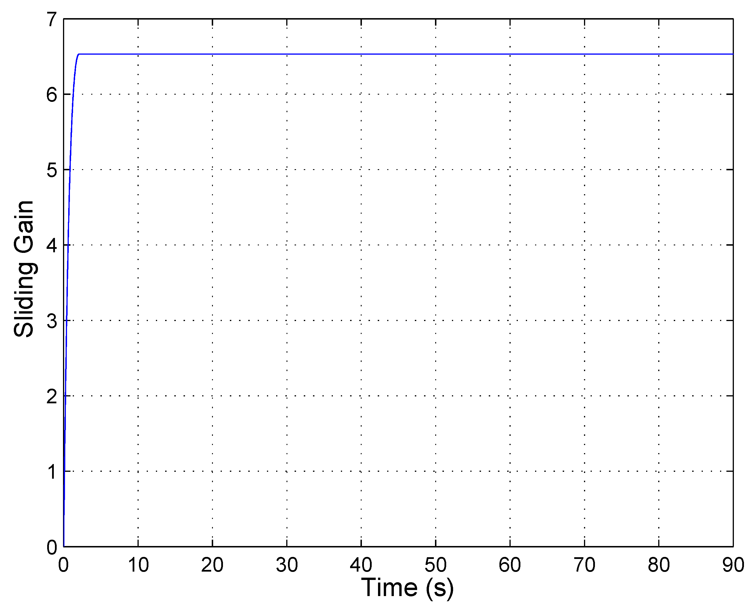
Figure 20 shows the sliding gain value that is adapted online in order to compensate the system uncertainties. As in the previous example, the sliding gain value is incremented until the value of the sliding gain can compensate the uncertainties of the system.
Figure 21 shows the sliding variable and
Figure 22 shows the control signal.
Figure 23 shows the turbine mechanical power produced by this pressure drop for this system without optimum tracking control. Unlike the previous optimum tracking SMC, the undesirable stalling behavior that produces power losses can be observed in this figure. The average value of the mechanical power produced in this case is 17.3 kW (green line).
Figure 24 shows the electrical power generated whose average value is 12.9 kW (green line).
Figure 25 shows the flow coefficient for the case without optimum tracking control. In this figure, it can be seen that the flow coefficient exceeds the critical value
, and the stalling behavior therefore appears in the dynamics of the Wells turbine because the flow coefficient is not optimized in order to increment the mechanical power generation.
Comparing
Figure 17 and
Figure 24, it can be observed that the electrical power generated by an OWC system can be improved in two ways by means of the generator speed control. On the one hand, the optimum speed tracking improves the OWC system performance providing an optimum value of the flow coefficient for the Wells turbine that produces the maximum mechanical energy extraction from the ocean waves. On the other hand, the optimum speed tracking can also be used to avoid the stalling behavior in the Wells turbine dynamics, because the flow coefficient can be maintained below the critical value
.
In the next simulation example, the proposed control scheme is evaluated under irregular waves. In this case, these irregular waves produce the pressure drop profile shown in
Figure 26.
Figure 27 shows the turbine mechanical power produced by this pressure drop using the proposed control scheme. In this figure, the green line shows the average value of the produced mechanical power.
Figure 28 shows the electrical power generated, and the average value of this power is also shown in the green line.
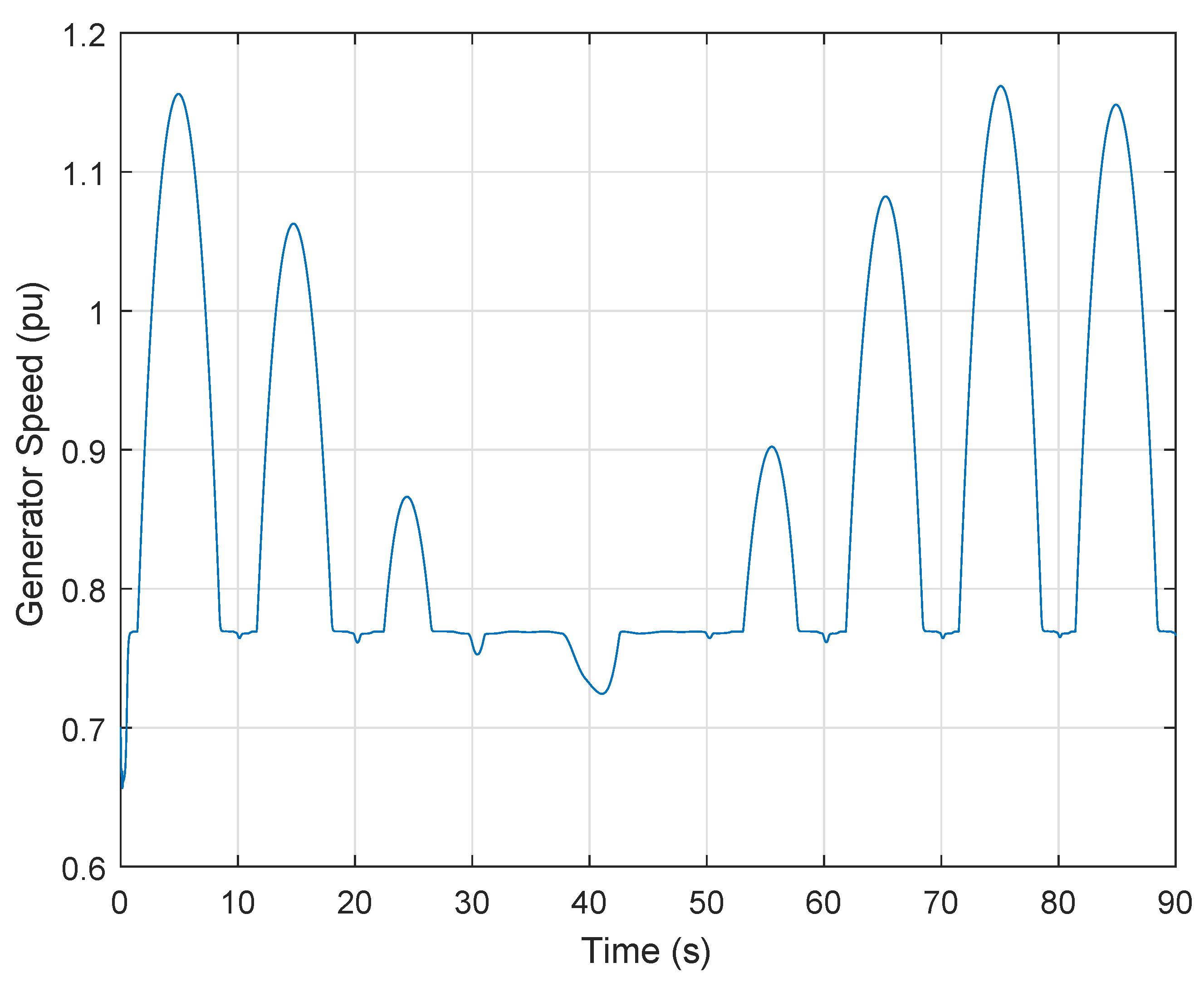
Figure 29 shows the generator speed whose value is regulated by this adaptive SMC in order to optimize the mechanical power extraction from the Wells turbine system.
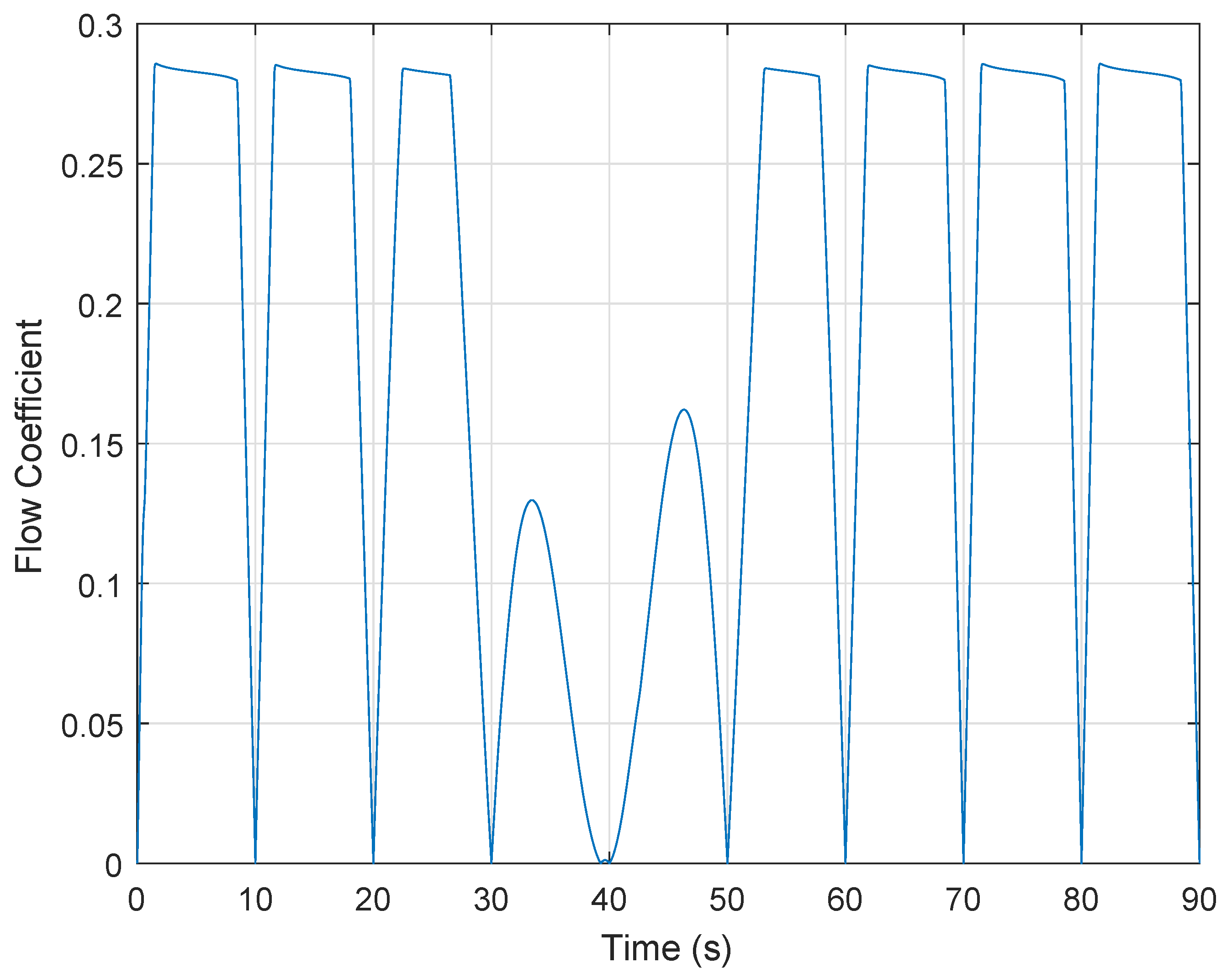
Figure 30 shows the flow coefficient for the SMC case under irregular waves scenario. This figure shows that the speed regulation of the Wells turbine improves the flow coefficient values and hence optimizes the mechanical power generation. Moreover, the proposed speed regulation also avoids the stalling behavior that usually happens in the Wells turbine because the flow coefficient is maintained below the critical value
.


