1. Introduction
Due to the problems of hydraulic brakes with respect to the maintenance of oil and oil pressure lines, as well as the efficiency of hydraulic pump operation in conventional brake systems in the automotive field, EMB is drawing more attention [
1,
2].
At the initial stage of the development of EMB, a wedge brake structure was used for the generation of maximum clamping force in the caliper under a low input voltage of 12 Vdc. However, a great deal of research into electric vehicles has made it possible to use 42 Vdc input voltage to achieve brake control of the caliper in the vertical direction of the brake disc directly [
3].
There have been numerous studies on motor control methods that address clamping force control, including PI controller using basic control of current and speed under vector control [
4], control of clamping force using a sliding mode controller [
5], adaptive sliding mode control using a neural network to estimate [
6], estimation methods of clamping force considered as gear friction [
7], estimated control of clamping force using the rotor position due to impossible applications of force sensors based on the spatial constraints of the driving part [
8,
9], observer-based sensor-less robust force control methods [
10], and fault diagnosis and tolerant control techniques based on the failure of the sensor [
11,
12,
13,
14,
15,
16]. Despite the number of studies, challenges still remain in terms of improving the safety requirements in automotive field, as well as the aspect of increasing costs of the entire braking system due to the complexity of the control system in comparison with hydraulic systems.
Studies are being actively conducted in the field of the railroad, such as the increase of transportation capacity and the upgrade of performance and miniaturization. In terms of the braking system, which is an important component of a train, applying EMB to the brake system is drawing attention as an alternative to existing pneumatic braking systems. EMB can decrease the volume of the entire braking system by up to 50% by eliminating the air compressor, air container for braking, piping for braking, valves, etc., which unnecessarily take up space at the bottom of the train, while it can also perform high-precision braking control and reduce latency time through fast response control. In addition, it is possible to design a structure that allows the brakes installed on different axles to share the braking force, even if one or more brakes breaks down. In Europe, an electric motor-type combined with a spring, called the Spring Loaded Brake System (SLBS) driving system, was developed and applied to low-speed light rail vehicles such as trams and monorails. In Korea, EMB clamping force performance had been tested by replacing the pneumatic braking part with the caliper, and was applied in urban railway vehicles with electric mechanical systems [
17]. However, this mechanical torque transmission structure used ball screw-type transmission, which is different from the spur gear and camshaft-type transmission used in this paper.
This research study involves the simulation and experimental results of the EMB system. The output clamping force of the caliper, the braking force of the EMB system, and decelerating performance are predicted in an analytical approach using a Matlab/Simulink simulation, and the simulation results are compared with experimental results measured by the clamping force sensors of the EMB test rig. In addition, it is proposed to add an anti-windup controller to improve the PI current control and maximum clamping force performance for the control of output torque. The experimental results showed that the brake design specification of HEMU-430X can be satisfied, ensuring the possibility of applying EMB system to trains.
3. Simulation Results of the EMB System
SPMSM mathematical modeling is necessary for the vector control simulation using Matlab/Simulink (R2018a, The MathWorks, Inc., Natick, MA, USA). The voltage equation of the synchronous d-q axis frame for SPMSM can be expressed as [
18]:
where
is angular velocity,
is resistance of stator,
and
are d-q axis inductance of stator,
and
are synchronous d-q axis current of stator,
is flux linkage.
From Equations (1) and (2), the output torque of SPMSM can be expressed as:
From Equation (3), because of the mechanical structure of SPMSM, the d-q axis inductance
and
are designed with the same value, as shown in
Table 1. Therefore, the SPMSM has no reluctance torque and the d-axis current
has no impact on the output torque. Finally, output torque is defined as follows:
where
is number of poles.
Figure 2 shows the relationship between current vector and output torque from Equations (3) and (4). From
Figure 2, SPMSM can be controlled with minimum current when
is zero and all stator current input
is controlled by
.
The mechanical part of Matlab/Simulink is constructed based on
Figure 3b. The mechanical clamping force and the braking characteristics of EMB can be predicted analytically. A Train Brake Model (TBM) block is constructed using a Shoe Brake for the modeling, similar to the caliper structure in
Figure 1. The torque output of the motor and reduction gear ass’y generated in
Figure 3a is used as an input of TBM that consists of the wheel and axle ass’y. If the wheel and axle ass’y moves at a certain constant velocity, the braking force, braking distance and deceleration speed can be predicted during the motor torque input. However, because Matlab/Simulink cannot implement a motor stall operation in the braking state, the output torque is used as an input value of TBM as the motor is rotated in the normal state.
Figure 4 shows the wave form of current control of the d-q axis for the SPMSM. The standard current values of the q axis and the d axis are entered as 10 A and 0 A, respectively, and it is shown that both d-q axis follow the reference value within 40 ms.
Figure 5a shows the torque output value of the motor according to the reference current value of the q-axis, and
Figure 5b shows the clamping force output value generated in the mechanical modeling by the reduction ratio between the first reduction gear and the second reduction gear from
Figure 1. The output rotating torque value of the motor is 1.75 Nm at a q-axis input current reference of 10 A, and the clamping force of the pad at this time is 51.5 kN.
Figure 6 shows the output results of the deceleration speed and braking force calculated in the TBM in
Figure 3. Deceleration speed is calculated assuming that the wheel and axle in the TBM of 10 kg moves at a constant initial velocity of 300 km/h during the simulation time.
Figure 6 shows that the brake is activated within 0.2 s, and the wheel and axle stop after moving a distance of 12 m. The braking force at that moment is 10.4 kN. Braking force can be converted to clamping force per caliper and expressed as:
where
is clamping force per caliper,
is braking force of system,
D is effective diameter ratio, and
is coefficient of friction. According to
Figure 5b, braking force output of TBM can be verified from Equation (5).
4. Experimental Results of the EMB system
Figure 7 shows the installation of the EMB test rig for the performance test. The experimental results from the EMB test rig are compared with the Matlab/Simulink simulation results in order to verify the EMB performance.
Figure 7b shows the EMB applied to the caliper, which is the same type as the pneumatic brake of the HEMU-430X, as shown in
Figure 1. Measurement of clamping force was performed by removing pads from both sides of the caliper in which the braking pads were installed and attaching two equivalent sensors (Loadcell). The specifications of the sensor for the measurement of clamping force are shown in
Table 2. The output of the Loadcell is measured by converting to voltage through an amplifier. The maximum clamping force and the response time to reach the maximum clamping force were recorded by the output waveform from the scope.
Figure 8 shows the experimental clamping force results for the conventional pneumatic brake installed in the HEMU-430X. The clamping force was measured with the sensor installed as shown in
Figure 7b by injecting the same pneumatic pressure as that of an actual vehicle. At that time, no overshoot occurred in the transient response. The response time from the initial zero clamping force to the maximum clamping force was 900 ms, and the maximum clamping force was 51.3 kN. When the brake is actuated, the occurrence of overshoot has a bad effect on ride comfort for passengers, caused by jerk. In this paper, SPMSM control was done by minimizing the overshoot in the transient response characteristic of the EMB system, and experimental results were compared with the pneumatic braking system.
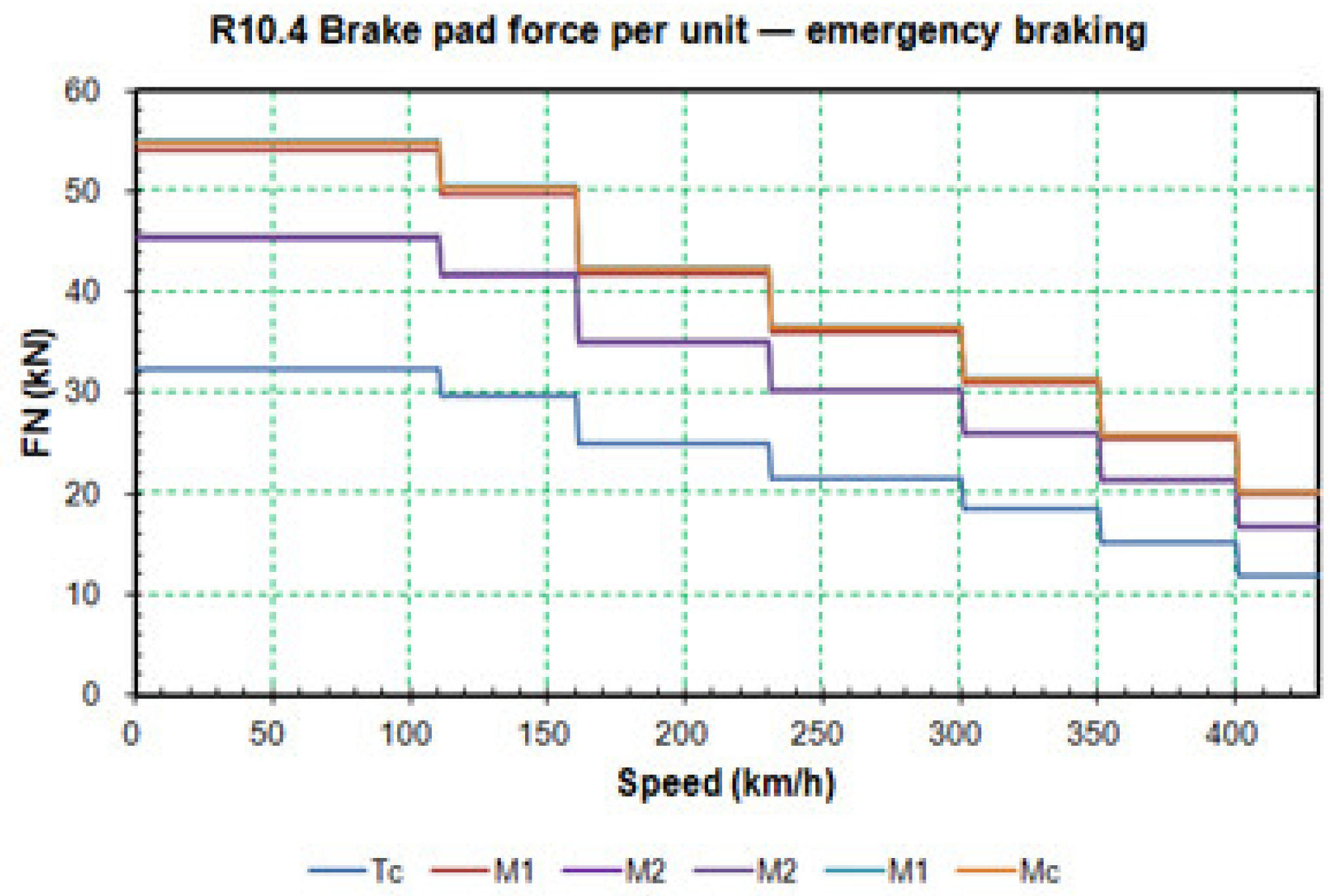
Figure 9 shows the reference values for emergency braking in accordance with the speed of the HEMU-430X. As shown in
Figure 9, maximum braking force occurs at 110 km/h in each vehicle. The reference value for maximum braking force at that time was determined to be 54 kN. Compared to the experimental values in
Figure 8, there was an error of about 5% at the maximum clamping force.
Figure 10a shows the experimental clamping force waveform of the EMB. As mentioned above in the previous section, the q-axis current was applied to control EMB. As shown in
Figure 8, to generate similar output clamping force to the pneumatic brake, the reference current value of q-axis was set at 10 A. The gain of the PI current controller was set in order not to generate overshoot. At that time, the transient response time to reach the maximum clamping force was 410 ms, and the maximum clamping force was measured at about 51.8 kN. Compared to the pneumatic system, the transient response time to reach the maximum clamping force was faster by more than 50%. There was an error in output torque that was within 1% compared to the result of the simulation in
Figure 5. From Equation (6), when the current of the q-axis is applied to 10 A, the motor output torque is 1.75 Nm, and if the reduction gear ratio is considered, the motor output torque is 1.7547 Nm, based on the experiment results of a clamping force of 51.8 kN. This shows that the calculation torque and the experimental torque values are almost the same.
where
is pole pair.
Figure 10b shows the transient response time in accordance with the clamping force reference input. After the synchronous current reference input of the q-axis is applied, the clamping force of the EMB occurs within 50 ms. In addition, the total time of 450 ms is measured until the occurrence of maximum clamping force. The EMB shows about a 2.5 s faster response time than the conventional pneumatic brake system, which has a latency time of about 3 s. This shows that the reduction of the braking distance is about 200 m, in the case of a train running at a speed of 300 km/h.
Figure 11a shows the synchronous current control experimental result of q-axis in SPMSM. When the q-axis current of 10 A is applied to the motor and the motor stall occurs, at that time, the motor current increases rapidly under the brake pads and cannot move any more. However, the q-axis output current tracks stably to the reference current. In the case of the current control simulation results in
Figure 5, because Matlab/Simulink simulation uses the motor output torque under a normal rotation state, the waveform of the q-axis current control is different from EMB experimental results.
Figure 11b shows the mechanical rotation angle that occurs in accordance with the rotation of the motor. One sawtooth wave occurs when the motor rotates once, and a straight line waveform is shown when the motor rotation stops. The maximum clamping force is generated and maintained at the time of the motor stopping, as can be seen from the wave form. A total of 19 rotations were carried out before the occurrence of the maximum clamping force, and the rotation speed was measured at about 2800 rpm.
As mentioned above, the maximum clamping force of the experimental result is 4% smaller than the design specifications of the HEMU-430X at 110 km/h, as shown in
Figure 9. This paper suggests a PI controller which includes an anti-windup controller. Anti-windup controllers are used widely in industry to prevent the saturation phenomenon of integrators. Integrator saturation leads to a step response with a large overshoot and a high settling time. There has been a great deal of research on anti-windup PI control schemes. In this paper, the tracking back calculation scheme is applied to reduce the settling time and improve the clamping force.
Figure 12 shows the anti-windup PI control schemes [
19]. In the linear range, if
and
are the same,
is applied to the integrator input. In the saturation range,
and
are different, at that time,
is applied to the integrator input. Usually, an anti-windup gain of
is selected. Appropriate gain choice results in fast transient response, because the integrator is reset quickly. If the anti-windup gain value is too high, errors can cause input saturation.
Figure 13 shows the application of anti-windup controller in the EMB system. Input values are divided into a synchronous d-q axis frame. The output voltages of the three-phase inverter was limited by the control programing. In addition, anti-windup gain
was denoted to be
.
Figure 14 shows the experimental results for clamping force when an anti-windup controller is added. The current references for the synchronous d-q axis frame of 0 A and 10 A, respectively, were applied. As shown in
Figure 14a, the maximum clamping force value was measured as being 54 kN, and overshoot did not occur at transient response.
Figure 14b shows the output latency time according to the input of the q-axis reference current, and it took 170 ms. In comparison to
Figure 10, the time taken to reach the maximum clamping force and the latency time increased by 90 ms and 120 ms, respectively. It is thought that the response time was delayed due to the increase in the calculation time of the EMB inverter controller.
Figure 15 shows the current control waveform at the time of the occurrence of maximum clamping force. Compared to
Figure 11, the current of the q-axis increased by about 2 A under the motor stall state. However, the tracking performance to the reference current was faster by more than 1 s. The sawtooth width under the transient response is different, because the rising time of
Figure 15b is 90 ms longer than
Figure 11b. In addition, the angle values under the motor stall state are different in accordance with clamping force. If electric parts, especially the switching devices of inverters, are designed to have a current margin, this control method will not affect the EMB system. In addition, as shown in
Figure 15b, under the motor stall state, the sustained performance of the clamping force was the same.
Table 3 shows the experimental results for clamping force according to the synchronous frame current reference of the q-axis in the EMB and the braking steps corresponding to each operation speed of HEMU-430X in
Figure 9. The braking force was divided into a total of 7 stages, and the clamping force output for each braking step, corresponding to each speed, was satisfied in all areas of speed through the adjustment of the synchronous-frame d-axis current reference for the EMB.


