Microgrid Islanding Detection Based on Mathematical Morphology


Abstract
:1. Introduction
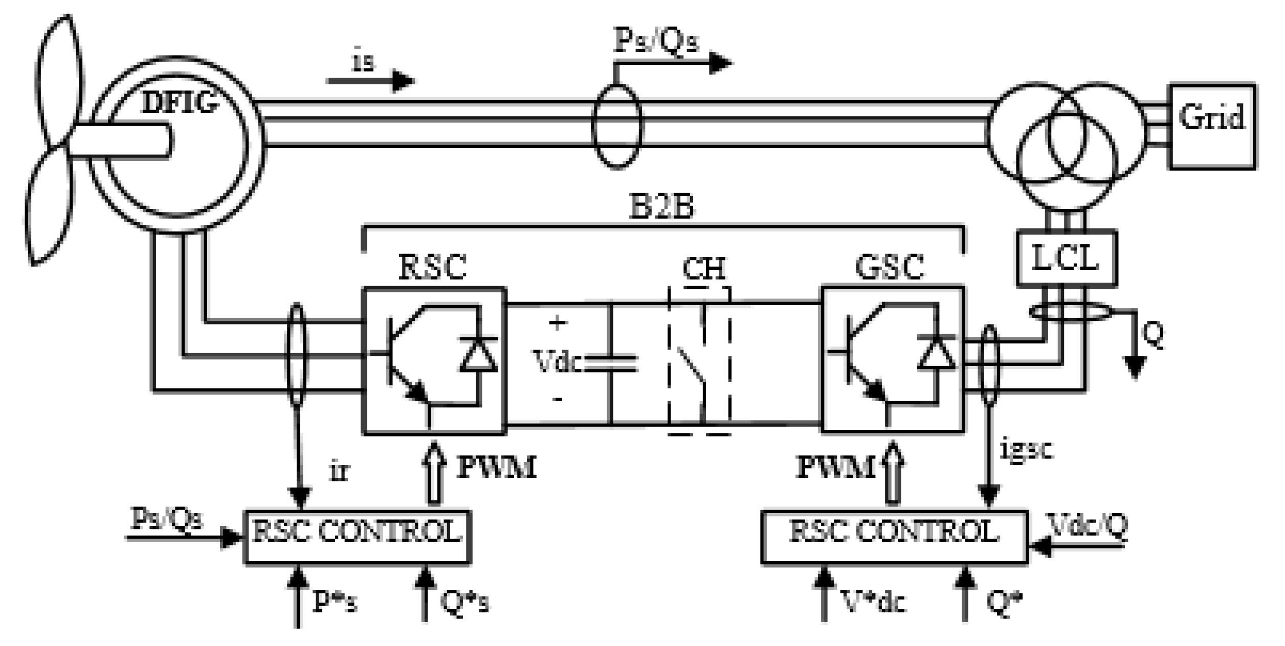
2. DFIG Modeling
3. Overview of Mathematical Morphology
3.1. Dilation and Erosion
3.2. Opening and Closing
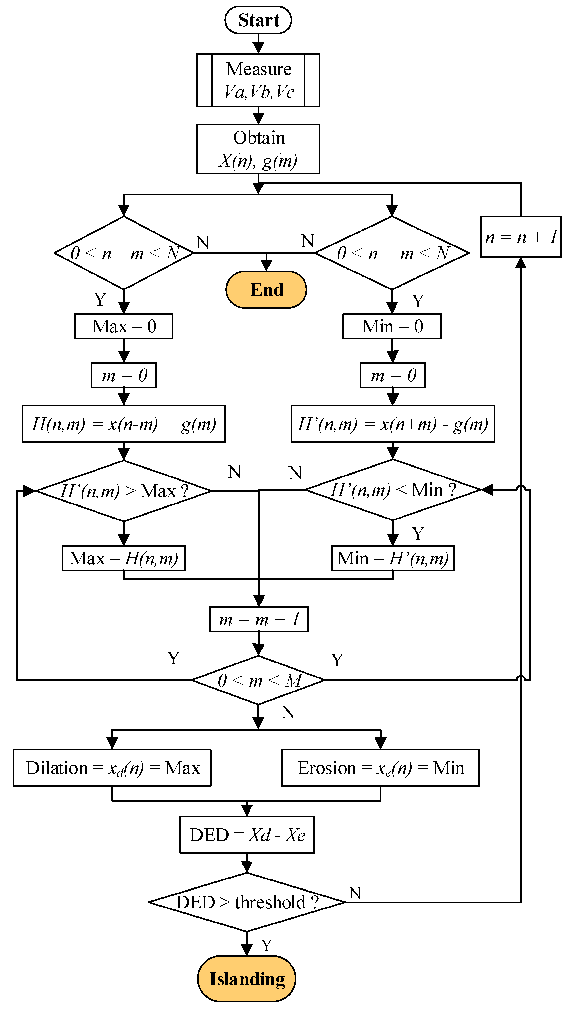
4. Proposed Islanding Detection Method
5. Simulation Results
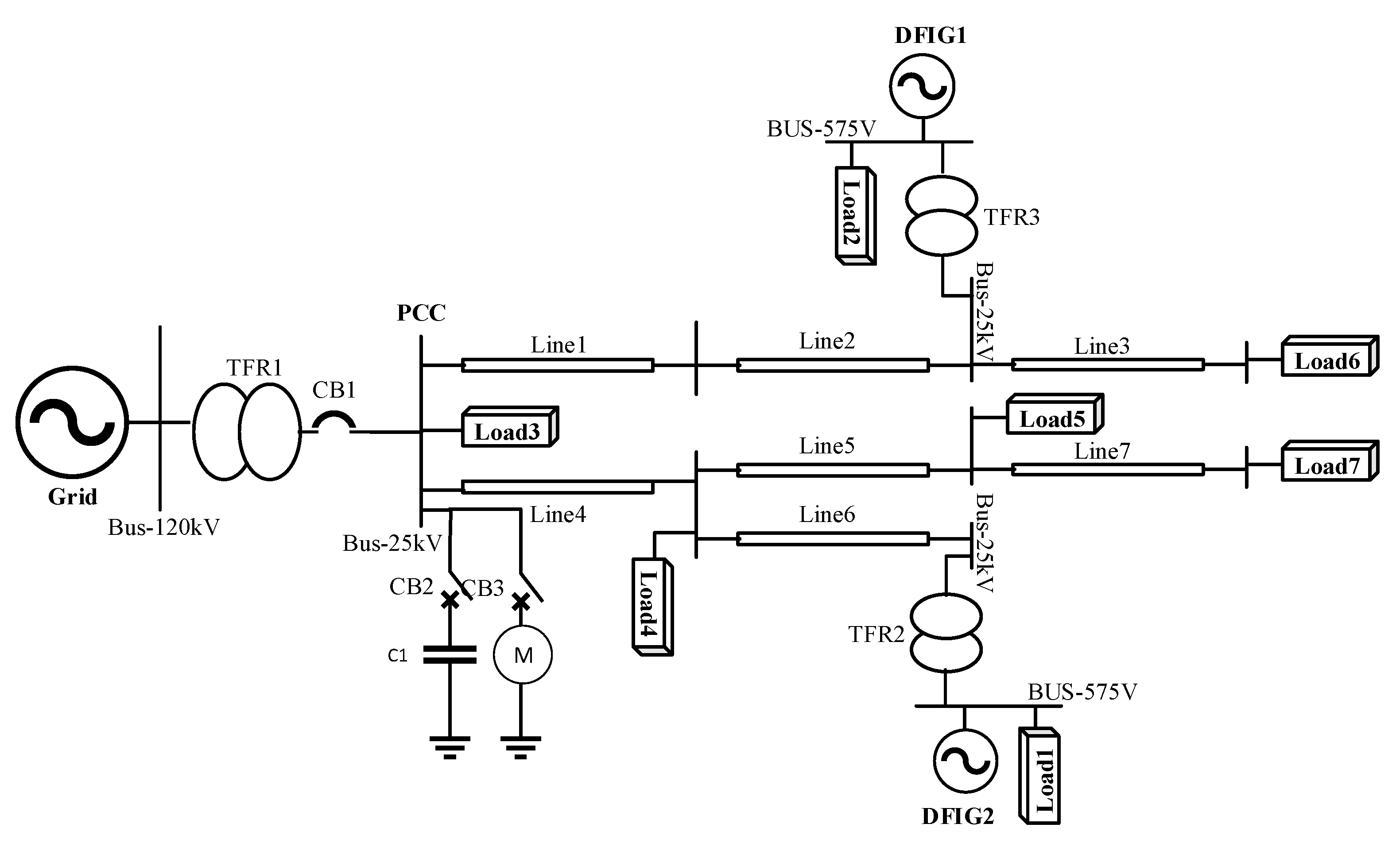
5.1. Test System
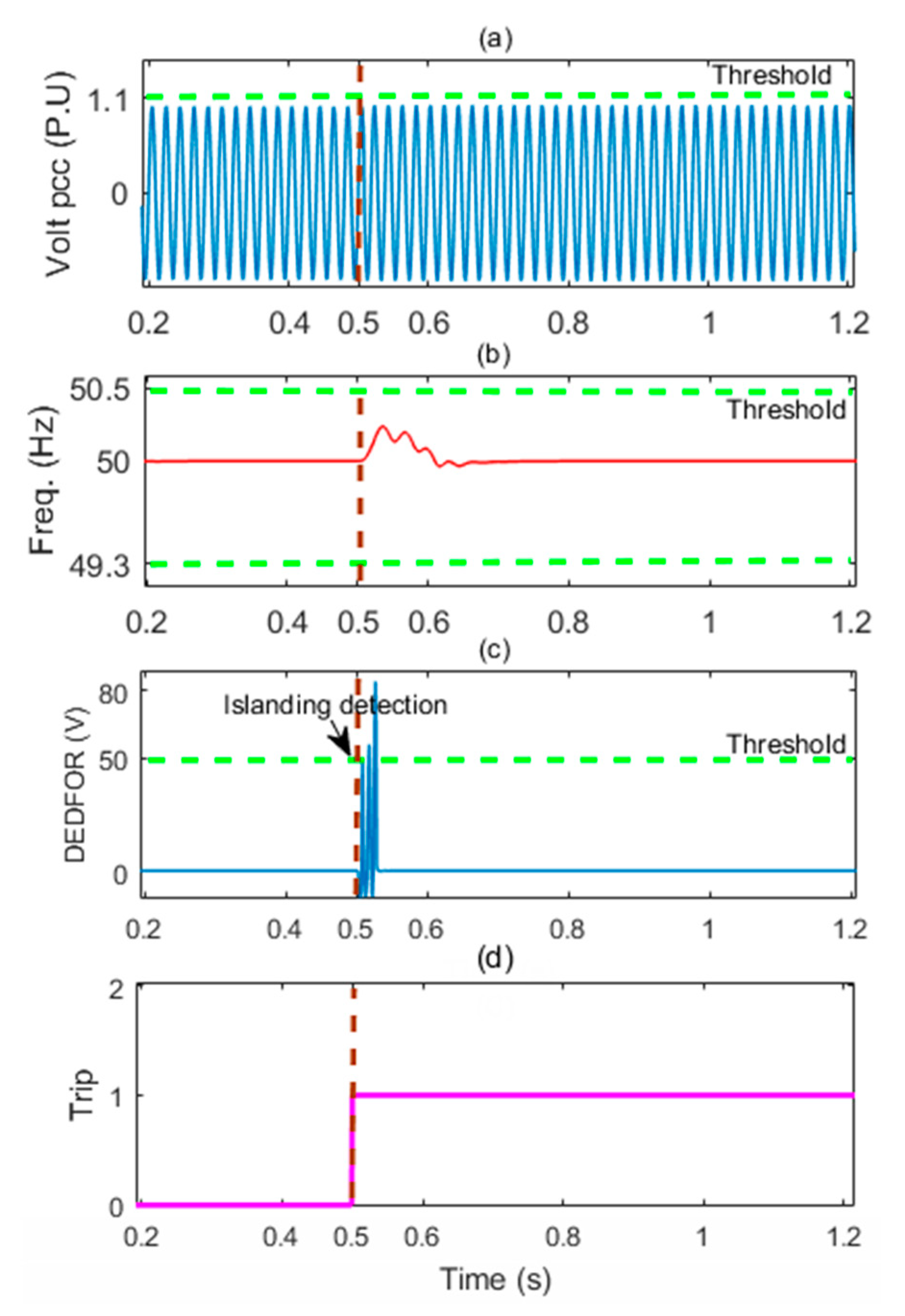
5.2. Case 1: Islanding
5.3. Case 2: NDZ Determination
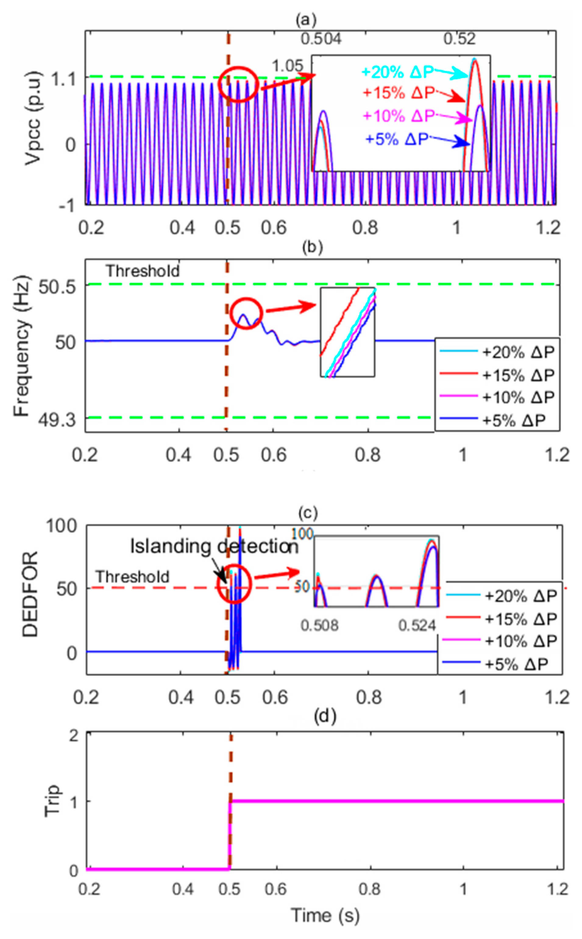
5.3.1. Scenario I
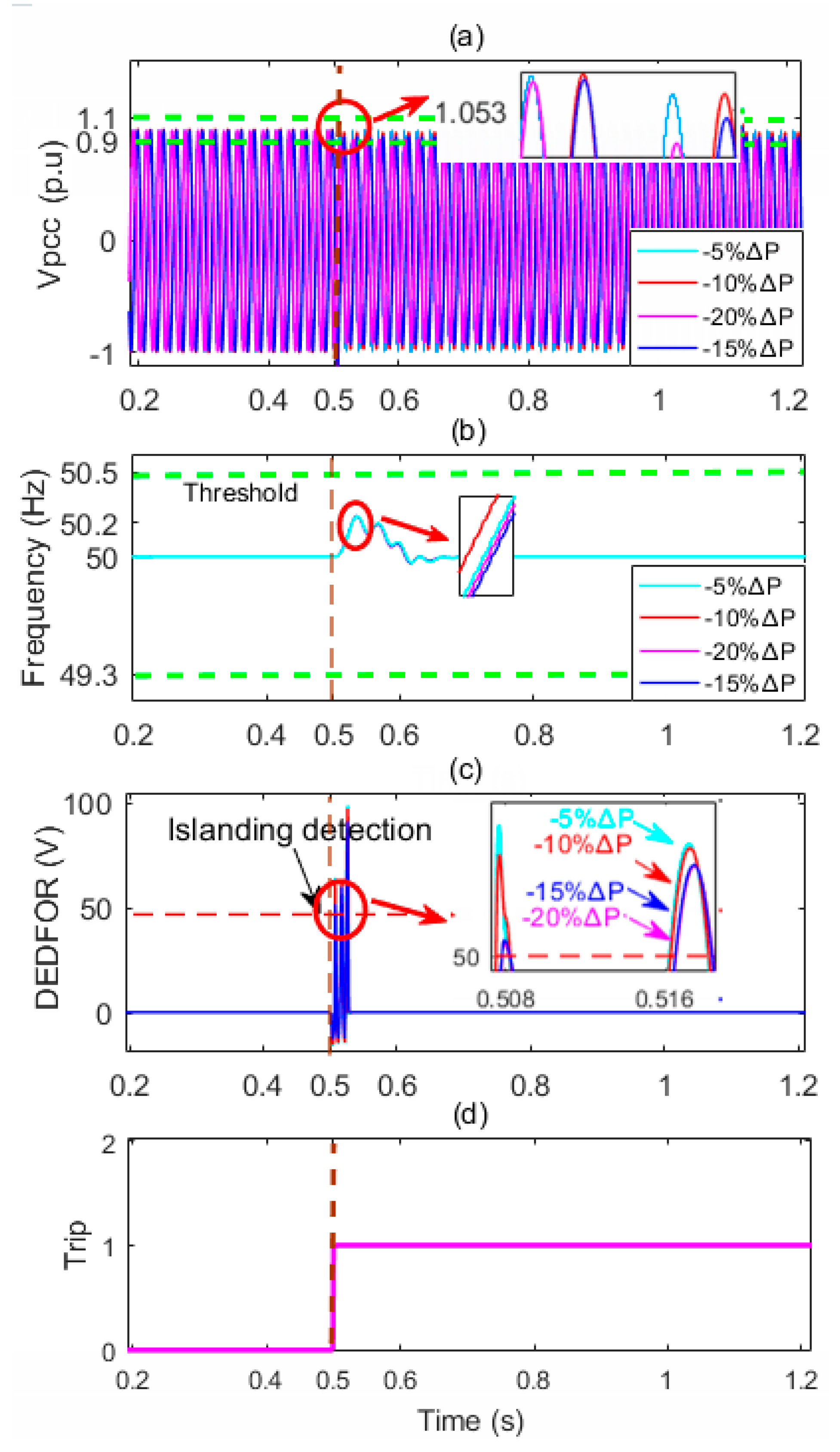
5.3.2. Scenario II
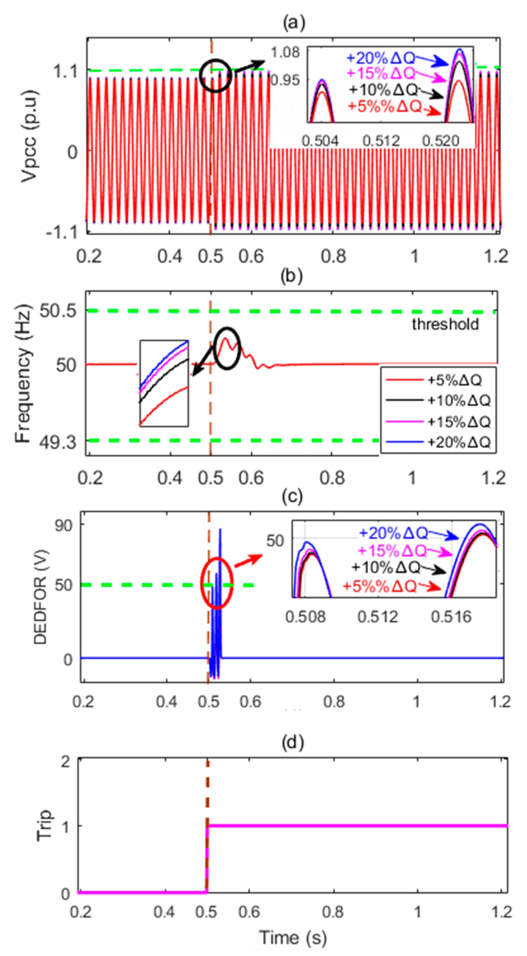
5.3.3. Scenarios III, IV
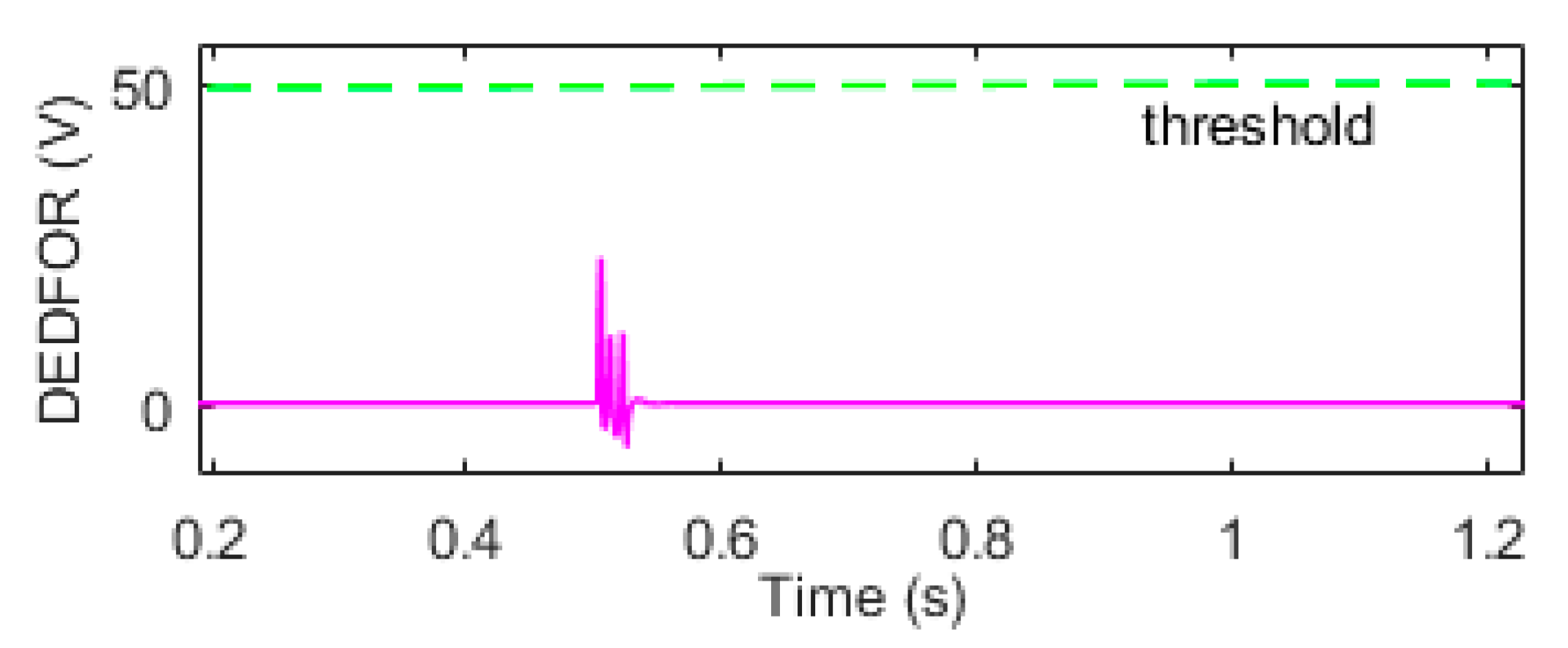
5.4. Case 3: Capacitor Switching Condition
5.5. Case 4: Motor Starting
5.6. Case 5: Load Change
6. Conclusions
Author Contributions
Funding
Conflicts of Interest
Nomenclature
| Load Real Power | |
| DG Real Power | |
| Real Power Imbalance Limits | |
| Load Power | |
| DG Reactive Power | |
| Reactive Power Imbalance Limits | |
| Voltage at PCC | |
| Source Impedance | |
| Source Resistance | |
| Source Reactance | |
| Source Inductance | |
| Source Voltage | |
| CB | Circuit Breaker |
| RMS | Root Mean Square |
| Load Impedance | |
| Load Resistance | |
| Load Inductance | |
| Load Capacity | |
| DG Impedance | |
| DG Resistance | |
| DG Reactance |
References
- Guo, F.; Wen, C.; Li, Z. Distributed optimal energy scheduling based on a novel PD pricing feedback strategy in smart grid. In Proceedings of the 2015 IEEE 10th Conference on Industrial Electronics and Applications (ICIEA), Auckland, New Zealand, 15–17 June 2015. [Google Scholar]
- Elsisi, M.; Soliman, M.; Aboelela, M.A.S.; Mansour, W. Model predictive control of plug-in hybrid electric vehicles for frequency regulation in a smart grid. IET Gener. Transm. Distrib. 2017, 11, 3974–3983. [Google Scholar] [CrossRef]
- Wang, Y.; Mao, S.; Nelms, R.M. On hierarchical power scheduling for the macrogrid and cooperative microgrids. IEEE Trans. Ind. Inform. 2015, 11, 1574–1584. [Google Scholar]
- Microgrid Exchange Group. DOE Microgrid Workshop Report; The U.S. Department of Energy (DOE): San Diego, CA, USA, 2011.
- Smith, M.; Ton, D. Key connections: The U.S. department of energy’s microgrid initiative. IEEE Power Energy Mag. 2013, 11, 22–27. [Google Scholar] [CrossRef]
- Farzin, H.; Fotuhi-Firuzabad, M.; Moeini-Aghtaie, M. Stochastic energy management of microgrids during unscheduled islanding period. IEEE Trans. Ind. Inform. 2017, 13, 1079–1087. [Google Scholar] [CrossRef]
- Che, L.; Shahidehpour, M.; Alabdulwahab, A.; Al-Turki, Y. Hierarchical coordination of a community microgrid with AC and DC microgrids. IEEE Trans. Smart Grid 2015, 6, 3042–3051. [Google Scholar] [CrossRef]
- Ghanbari, N.; Mokhtari, H.; Bhattacharya, S. Optimizing operation indices considering different types of distributed generation in microgrid applications. Energies 2018, 11, 894. [Google Scholar] [CrossRef]
- Han, Y.; Ma, R.; Cui, J. Adaptive higher-order sliding mode control for islanding and grid-connected operation of a microgrid. Energies 2018, 11, 1459. [Google Scholar] [CrossRef]
- Zheng, T.; Yang, H.; Zhao, R.; Kang, Y.C.; Terzija, V. Design, evaluation and implementation of an islanding detection method for a micro-grid. Energies 2018, 11, 323. [Google Scholar] [CrossRef]
- Jia, K.; Ren, Z.; Li, L.; Xuan, Z.; Thomas, D. High-frequency transient comparison based fault location in distribution systems with DGs. IET Gener. Transm. Distrib. 2017, 11, 4068–4077. [Google Scholar] [CrossRef] [Green Version]
- Alaboudy, A.H.K.; Zeineldin, H.H. Islanding detection for inverter-based dg coupled with frequency-dependent static loads. IEEE Trans. Power Deliv. 2011, 26, 1053–1063. [Google Scholar] [CrossRef]
- Ghalavand, F.; Al-omari, A.; Karegar, H.K.; Karimipour, H. Hybrid islanding detection for ac/dc network using DC-link voltage. In Proceedings of the IEEE International Conference on Smart Energy Grid Engineering (SEGE), Oshawa, ON, Canada, 12–15 August 2018. [Google Scholar]
- Issa, W.R.; Abusara, M.A.; Sharkh, S.M. Control of transient power during unintentional islanding of microgrids. IEEE Trans. Power Electron. 2015, 30, 4573–4584. [Google Scholar] [CrossRef]
- Salles, D.; Freitas, W.; Vieira, J.C.M.; Venkatesh, B. A practical method for nondetection zone estimation of passive anti-islanding schemes applied to synchronous distributed generators. IEEE Trans. Power Deliv. 2015, 30, 2066–2076. [Google Scholar] [CrossRef]
- Cagnano, A.; De Tuglie, E.; Cicognani, L. Prince—Electrical energy systems lab: A pilot project for smart microgrids. Electr. Power Syst. Res. 2017, 148, 10–17. [Google Scholar] [CrossRef]
- Cagnano, A.; De Tuglie, E.; Trovato, M.; Cicognani, L.; Vona, V. A simple circuit model for the islanding transition of microgrids. In Proceedings of the IEEE 2nd International Forum on Research and Technologies for Society and Industry Leveraging a better tomorrow (RTSI), Bologna, Italy, 7–9 September 2016. [Google Scholar]
- IEEE Standard. 1547–2003—IEEE standard for interconnecting distributed resources with electric power systems. IEEE Stand. Assoc. 2003. [Google Scholar] [CrossRef]
- IEEE Standard. 1547–2018—IEEE standard for interconnection and interoperability of distributed energy resources with associated electric power systems interfaces (revision of IEEE Std 1547–2003). IEEE Stand. Assoc. 2018. [Google Scholar] [CrossRef]
- Reis, M.V.G.; Barros, T.A.S.; Moreira, A.B.; Paulo, S.N.F.; Ernesto, R.F.; Villalva, M.G. Analysis of the Sandia Frequency Shift (SFS) islanding detection method with a single-phase photovoltaic distributed generation system. In Proceedings of the 2015 IEEE PES Innovative Smart Grid Technologies Latin America (ISGT LATAM), Montevideo, Uruguay, 5–7 October 2015. [Google Scholar]
- Reis, M.V.G.; Villalva, M.G.; Barros, T.A.S.; Paulo, S.N.F.; Moreira, A.B.; Ernesto, R.F. Active frequency drift with positive feedback anti-islanding method for a single phase two-stage grid-tied photovoltaic system. In Proceedings of the 2015 IEEE 13th Brazilian Power Electronics Conference and 1st Southern Power Electronics Conference (COBEP/SPEC 2015), Fortaleza, Brazil, 29 November–2 December 2015. [Google Scholar]
- Raza, S.; Mokhlis, H.; Arof, H.; Laghari, J.A.; Wang, L. Application of signal processing techniques for islanding detection of distributed generation in distribution network: A review. Energy Convers. Manag. 2015, 96, 613–624. [Google Scholar] [CrossRef]
- Laaksonen, H. Advanced islanding detection functionality for future electricity distribution networks. IEEE Trans. Power Deliv. 2013, 28, 2056–2064. [Google Scholar] [CrossRef]
- Lin, Z.; Xia, T.; Ye, Y.; Zhang, Y.; Chen, L.; Liu, Y.; Tomsovic, K.; Bilke, T.; Wen, F. Application of wide area measurement systems to islanding detection of bulk power systems. IEEE Trans. Power Syst. 2013, 28, 2006–2015. [Google Scholar] [CrossRef]
- Sun, R.; Centeno, V.A. Wide area system islanding contingency detecting and warning scheme. IEEE Trans. Power Syst. 2014, 29, 2581–2589. [Google Scholar] [CrossRef]
- Hosani, M.A.; Qu, Z.; Zeineldin, H.H. Development of dynamic estimators for islanding detection of inverter-based DG. IEEE Trans. Power Deliv. 2015, 30, 428–436. [Google Scholar] [CrossRef]
- Kim, J.-H.; Kim, J.-G.; Ji, Y.-H.; Jung, Y.-C.; Won, C.-Y. An islanding detection method for a grid-connected system based on the Goertzel algorithm. IEEE Trans. Power Electron. 2011, 26, 1049–1055. [Google Scholar] [CrossRef]
- Jia, K.; Wei, H.; Bi, T.; Thomas, D.W.P.; Sumner, M. An islanding detection method for multi-DG systems based on high-frequency impedance estimation. IEEE Trans. Sustain. Energy 2017, 8, 74–83. [Google Scholar] [CrossRef]
- Emadi, A.; Afrakhte, H.; Sadeh, J. Fast active islanding detection method based on second harmonic drifting for inverter-based distributed generation. IET Gener. Transm. Distrib. 2016, 10, 3470–3480. [Google Scholar] [CrossRef]
- Galleani, L.; Tavella, P. Robust detection of fast and slow frequency jumps of atomic clocks. IEEE Trans. Ultrason. Ferroelectr. Freq. Control 2017, 64, 475–485. [Google Scholar] [PubMed]
- Mazhari, I.; Jafarian, H.; Enslin, J.H.; Bhowmik, S.; Parkhideh, B. Locking frequency band detection method for islanding protection of distribution generation. IEEE J. Emerg. Sel. Top. Power Electron. 2017, 5, 1386–1395. [Google Scholar] [CrossRef]
- Sun, Q.; Guerrero, J.M.; Jing, T.; Vasquez, J.C.; Yang, R. An islanding detection method by using frequency positive feedback based on FLL for single-phase microgrid. IEEE Trans. Smart Grid 2017, 8, 1821–1830. [Google Scholar] [CrossRef]
- Reigosa, D.; Blanco, C.; Guerrero, J.M.; Briz, F. Evaluation of high frequency signal injection islanding detection based methods under non-linear-loads scenarios. In Proceedings of the 2016 IEEE Energy Conversion Congress and Exposition (ECCE), Milwaukee, WI, USA, 18–22 September 2016. [Google Scholar]
- Gu, C.J.; Wei, H.S.; Jia, K.; Bi, T.S.; Liu, B.H. Positive- and negative-sequence control strategy of grid-connected PV systems under balanced and unbalanced voltage sags. In Proceedings of the 12th IET International Conference on AC and DC Power Transmission (ACDC), Beijing, China, 28–29 May 2016. [Google Scholar]
- Hamzeh, M.; Rashidirad, N.; Sheshyekani, K.; Afjei, E. A new islanding detection scheme for multiple inverter-based dg systems. IEEE Trans. Energy Convers. 2016, 31, 1002–1011. [Google Scholar] [CrossRef]
- Zeineldin, H.H., Jr. Performance of the OVP/UVP and OFP/UFP method with voltage and frequency dependent loads. IEEE Trans. Power Deliv. 2009, 24, 772–778. [Google Scholar] [CrossRef]
- Ye, Z.; Kolwalkar, A.; Zhang, Y.; Du, P.; Walling, R. Evaluation of anti-islanding schemes based on nondetection zone concept. IEEE Trans. Power Electron. 2004, 19, 1171–1176. [Google Scholar] [CrossRef]
- Yin, J.; Diduch, C.P.; Chang, L. Islanding detection using proportional power spectral density. IEEE Trans. Power Deliv. 2008, 23, 776–784. [Google Scholar] [CrossRef]
- Liu, N.; Aljankawey, A.; Diduch, C.; Chang, L.; Su, J. Passive islanding detection approach based on tracking the frequency-dependent impedance change. IEEE Trans. Power Deliv. 2015, 30, 2570–2580. [Google Scholar] [CrossRef]
- Samui, A.; Samantaray, S.R. Wavelet singular entropy-based islanding detection in distributed generation. IEEE Trans. Power Deliv. 2013, 28, 411–418. [Google Scholar] [CrossRef]
- Hartmann, N.B.; dos Santos, R.C.; Grilo, A.P.; Vieira, J.C.M. Hardware implementation and real time evaluation of an ANN-based algorithm for anti-islanding protection of distributed generators. IEEE Trans. Ind. Electron. 2017, 65, 5051–5059. [Google Scholar] [CrossRef]
- Arachchige, L.W.; Rajapakse, A. A pattern recognition approach for detecting power islands using transient signals—Part I: Design and implementation. In Proceedings of the 2011 IEEE Power and Energy Society General Meeting, Detroit, MI, USA, 24–29 July 2011. [Google Scholar]
- El-Arroudi, K.; Joos, G.; Kamwa, I.; McGillis, D.T. Intelligent-Based approach to islanding detection in distributed generation. IEEE Trans. Power Deliv. 2007, 22, 828–835. [Google Scholar] [CrossRef]
- Khodaparastan, M.; Vahedi, H.; Khazaeli, F.; Oraee, H. A novel hybrid islanding detection method for inverter-based DGs using SFS and ROCOF. IEEE Trans. Power Deliv. 2017, 32, 2162–2170. [Google Scholar] [CrossRef]
- Dhar, S.; Dash, P.K. Harmonic profile injection-based hybrid active islanding detection technique for PV-VSC-based microgrid system. IEEE Trans. Sustain. Energy 2016, 7, 1473–1481. [Google Scholar] [CrossRef]
- Azim, R.; Li, F.; Xue, Y.; Starke, M.; Wang, H. An islanding detection methodology combining decision trees and Sandia frequency shift for inverter-based distributed generations. IET Gener. Trans. Distrib. 2017, 11, 4104–4113. [Google Scholar] [CrossRef]
- Murugesan, S.; Murali, V.; Daniel, S.A. Hybrid analyzing technique for active islanding detection based on d-axis current injection. IEEE Syst. J. 2017, 1–10. [Google Scholar] [CrossRef]
- Pena, R.; Clare, J.C.; Asher, G.M. Doubly fed induction generator using back-to-back PWM converters and its application to variable-speed wind-energy generation. IEE Proc. Electr. Power Appl. 1996, 143, 231–241. [Google Scholar] [CrossRef]
- Arguence, O.; Raison, B.; Cadoux, F. Comments on “impact of load frequency dependence on the NDZ and performance of the SFS islanding detection method”. IEEE Trans. Ind. Electron. 2017, 64, 7277–7279. [Google Scholar] [CrossRef]
- Heier, S. Grid Integration of Wind Energy: Onshore and Offshore Conversion System; Wiley: Hoboken, NJ, USA, 2014. [Google Scholar]
- Bayat, H.; Yazdani, A. A power mismatch elimination strategy for an MMC-based photovoltaic system. IEEE Trans. Energy Convers. 2018, 33, 1519–1528. [Google Scholar] [CrossRef]


| Standards | Detection Time | Frequency Range | Voltage Range |
|---|---|---|---|
| IEEE-1547 [19] | t < 2 s | 49.3 Hz f 50.5 Hz | 0.88 V 1.1 p.u |
| IEEE-929-2000 [20] | t < 2 s | 49.3 Hz f 50.5 Hz | 0.88 V 1.1 p.u |
| IEC-62116 [21] | t < 2 s | 48.5 Hz f 51.5 Hz | 0.85 V 1.15 p.u |
| Grid | Transformer: TFR1 |
|---|---|
| 120 kV, 50 Hz | Side1: Yg; Side2: ∆ |
| DGs: DFIG1,2 | 50 MVA, 120 kV/25 kV |
| 9 MW, 575 V, 50 Hz | = = 0.08/30 p.u, = = 500 p.u |
| Lines: Line 1, 2, 3, 4, 5, 6, 7 | = = 0.08 p.u |
| 50 Hz, 10 km | Transformer: TFR2,3 |
| 3 phase pi section | Side1: ∆; Side2: Yg |
| = 0.1153, = 0.413 (ohm/km) | 12 MVA, 25 kV/575 V |
| = 1.05 × 10⁻³, = 3.32 × 10⁻³ (H/km) | = = 0.025/30 p.u, = 500 p.u |
| = 11.33 × 10⁻⁹, = 5.01 × 10⁻⁹ (F/km) |
| Scenarios | Power Mismatch | Different Ranges | Constant Value |
|---|---|---|---|
| Scenario I | increased% | +5%,+10%, +15%, +20% | 100% |
| Scenario II | decreased% | −5%, −10%, −15%, −20% | 100% |
| Scenario III | Increased% | +5%, +10%, +15%, +20% | 100% |
| Scenario IV | decreased% | −5%, −10%, −15%, −20% | 100% |
© 2018 by the authors. Licensee MDPI, Basel, Switzerland. This article is an open access article distributed under the terms and conditions of the Creative Commons Attribution (CC BY) license (http://creativecommons.org/licenses/by/4.0/).
Share and Cite
Ghalavand, F.; Alizade, B.A.M.; Gaber, H.; Karimipour, H. Microgrid Islanding Detection Based on Mathematical Morphology. Energies 2018, 11, 2696. https://doi.org/10.3390/en11102696
Ghalavand F, Alizade BAM, Gaber H, Karimipour H. Microgrid Islanding Detection Based on Mathematical Morphology. Energies. 2018; 11(10):2696. https://doi.org/10.3390/en11102696
Chicago/Turabian StyleGhalavand, Fatemeh, Behzad Asle Mohammadi Alizade, Hossam Gaber, and Hadis Karimipour. 2018. "Microgrid Islanding Detection Based on Mathematical Morphology" Energies 11, no. 10: 2696. https://doi.org/10.3390/en11102696
APA StyleGhalavand, F., Alizade, B. A. M., Gaber, H., & Karimipour, H. (2018). Microgrid Islanding Detection Based on Mathematical Morphology. Energies, 11(10), 2696. https://doi.org/10.3390/en11102696