1. Introduction
In recent years, the DGs based on Renewable Energy Sources (RESs) have been playing an important role in the world’s energy supply systems [
1]. DGs can operate in parallel to the main grid or in a Microgrid (MG) mode [
2]. A microgrid can be defined as a group of DGs, load, communication systems, protection devises, and distributed energy storage systems that behave as a controllable entity [
3]. These DGs are mainly used to deliver renewable and clean energy such as Photovoltaic (PV) power to the utility through Grid-Connected Inverters (GCI). Increased changes in the stability of the MG are prompted by the uneven voltage and current due to harmonics, or Total Harmonic Distortion (THD) [
4]. The switching by Insulated-Gate Bipolar Transistor (IGBT) in power electronic devices such as GCIs are the origin of the harmonic distortion. Hence, power electronics systems have inherited the task of reducing the harmonic pollution that they create [
5]. To remove the current or voltage harmonics injected by power electronic devices and nonlinear loads, compensation devices such as Active Power filters (APFs) and Unified Power Quality Conditioner (UPQC) are being extensively employed [
6]. The current control strategy is the main part in APFs, and many current control schemes such as proportional-integral (PI) control [
7,
8], Proportional Resonant (PR) control [
9], hysteresis control [
10], and Deadbeat (DB) control [
11], have been proposed. A Droop control and a control scheme for injecting the negative sequence voltage are suggested in Reference [
12]. In Reference [
13], the utilization of secondary and tertiary controls for improving the voltage quality was proposed. Tonyma et al. [
14] in a capacity-limiting action for compensating the harmonic current and unbalanced current, proposed a multifunctional three-phase power conditioner. One of the problems is existence of zero-sequence circulating current flowing between parallel converters. It ought to be specified that in previous studies around three-phase MGs, the zero-sequence component of voltage and current in the grid-connected inverter in microgrids are not taken into account [
15,
16,
17].
V. Khadkikar in [
18] presents a comprehensive review of the UPQC to enhance the electric power quality at distribution levels. It provides an overview of the different possible UPQC system configurations for single-phase (two-wire) and three-phase (three-wire and four-wire) networks, different compensation approaches, and recent developments in the field. Paper [
19] proposed a synchronous reference frame control method for current unbalance compensation in the microgrid. This method is based on the proper control of Distributed Generations (DGs) interface converters. It also proposed the direct change of the current reference to compensate for current unbalance. The fault analysis with hybrid compensation for unbalanced distribution systems is discussed in Reference [
20]. The method employs the unbalanced three-phase model to analyse faults. Two matrices containing information on the topological characteristics of distribution networks were built along with the proposed hybrid-compensation method for analysis. Ting-Chia Ou et al. [
21] have shown dynamic operation and control strategies for a microgrid hybrid wind-Photovoltaic (PV)-Fuel Cell (FC) based power supply system. The system consists of the PV power, wind power, FC power, Static VAr Compensator (SVC), and an intelligent power controller. Paper [
22] proposed a novel intelligent damping controller for the Static Synchronous Compensator (STATCOM) to reduce the power fluctuations, voltage support, and damping in a hybrid power multi-system. This paper also discussed the integration of an offshore wind farm and a seashore wave power farm via a high-voltage, alternating current electric power transmission line that connects the STATCOM and the 12-bus hybrid power multi-system.
Author in [
23] proposed a novel unsymmetrical faults analysis method with hybrid compensation for microgrid (MG) distribution systems. The method employs the actual three-phase models to handle unsymmetrical faults. Likewise, two matrices, which are built from the topological characteristics of MG distribution networks, and then combined with the proposed hybrid compensation method for injecting branch mismatch currents caused by the fault are used to analyze the branch mismatch currents and bus mismatch voltages directly. Author in [
24] depicted a direct building algorithm for microgrid distribution ground fault analysis. In this paper, four possibilities of the network topology changes were considered with the proposed iterative process for ground fault analysis. Furthermore, it discusses the ground fault model of a battery energy storage system as a distributed energy resource, which can be used for both islanded and grid-connected modes. M. Tavakoli Bina et al. [
25] focused on the distribution unbalance, completing the available definitions in order to maintain tangible relationships between the level of unbalance and the cited consequences in distribution networks. Furthermore, practical works were performed on 11 selected 20 kV/0.4 kV substations within the Tehran north-west distribution system, where data loggers have been installed for 7 days to measure and record operating conditions of substations. Author [
26] proposed a UPQC topology with reduced DC-link voltage without compromising its compensation capability. The topology consists of capacitors in series with the interfacing inductor of the shunt active filter. This proposed topology also helps to match the dc-link voltage requirement of the shunt and series active filters of the UPQC.
Several studies, such as References [
27,
28,
29,
30,
31,
32] have proposed to use the APFs and UPQC for the cancellation of the voltage and current harmonics in MG. Along this line, Cheng et al. [
27] proposed a control strategy using distributed APFs to weaken the voltage harmonics of the system. In Reference [
28] an islanding detection method to detect the islanding phenomenon in a distribution system has been proposed. The proposed method is a hybrid islanding detection method which consists of a remote detection method and a passive method. The proposed method utilizes error rates of system parameter such as voltage and power to readjust generator controllers and maintain the system stability. Khadem S et al. [
29] has proposed the integration technique and powerful control of UPQC in Distributed Generation (DG) at the microgrid system. The results show that the UPQC can compensate for the voltage and current disturbance at the Point of Common Coupling (PCC) during interconnected mode. It is used in [
30] as a flexible digital-control design in a three-phase APF, which is used in variable-frequency grid conditions. The design consisted of a grid-frequency flexible resonant current adjuster and an upgraded synchronous-reference-frame phase-locked loop. In [
31], a single-stage 3 Phase-4 Wire grid-linked PV system that operated with a UPQC is presented. The UPQC with old load harmonic currents and atoning reactive power. The PV-UPQC denominated the power circuit of the system and is built from twin back-to-back linked neutral-point fastened inverters. In Reference [
32], an advanced UPQC has been proposed to fine tune the existing solutions for producing perfect sinusoidal air turbine-end currents within both bent-unbalanced load-terminal voltages and non-linear load cases.
The flexible UPQC and APFs could add outstanding redemption for current and voltage distortions, yet they are far from being a cost-effective solution because of high design and working costs. Compared to the additional investment for equipment purchasing, the improved control method of GCI can be practically incorporated.
It is to be noted that the current work targets the redemption of voltage and grid current harmonics. Wherever big disorders exist in the main grids, for example, the harmonic or THD, the GCI with the proposed control method is seldom useful to redeem the grid, including MG problems. To verify the performance of the suggested control solution, the system has been simulated and implemented in MATLAB/Simulink.
This paper is organized as follows:
Section 2 describes the control approach for a DG grid-connected inverter.
Section 3 presents the proposed control method for photovoltaic GCI. In this section, details of the entire control structure, including the power stage and the harmonic current and voltage compensation stage, are explained. Simulation results with three case studies are presented in
Section 4. Finally, in
Section 5, the conclusions are presented.
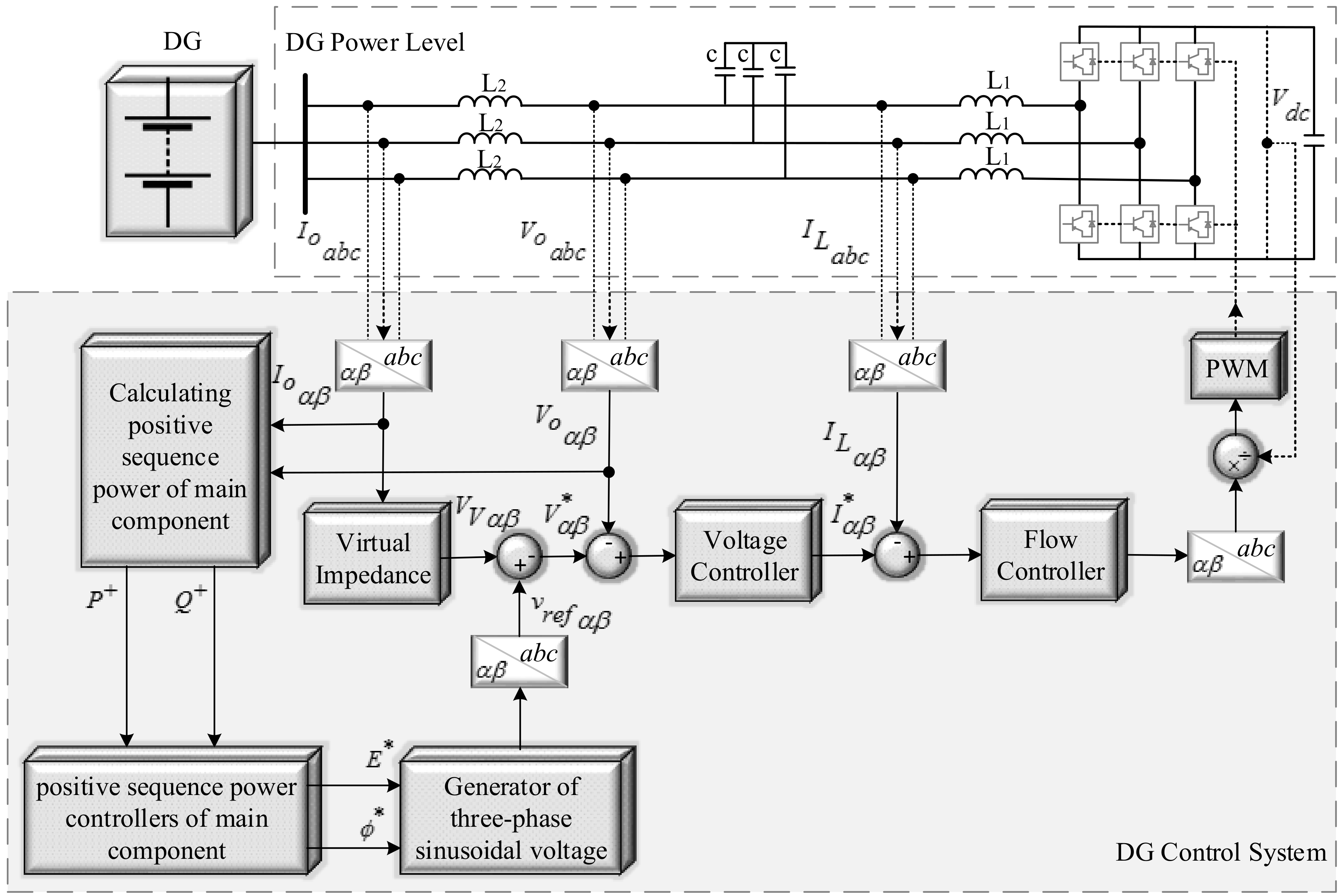
2. Control Approach for Distributed Generation (DG) Grid-Connected Inverter
Figure 1 shows the DG structure with power stage and local controller (without power quality controllers). Evidently, a feedforward loop might be incorporated to measure small variation of DC-link voltage (
. The DGs power level included the DC-link with voltage (
which can be assumed as an almost constant voltage in the DC link to control the interface inverter of the DG and inverter and an LCL-filter. An LCL filter is often used to interconnect an inverter to the utility grid in order to filter the harmonics produced by the inverter. However, as shown in this figure, it can be seen that fluctuations of the DC link voltage in the production of inverter gate signals can be considered by using a feed-forward loop.
This framework used the instantaneous active and reactive power theory to calculate the positive sequence of active and reactive powers [
33]. Droop controllers generated the droop-based voltage
in the control system. The “Mode Selector” switch enables the compensation modes to be chosen for harmonic and voltage or current unbalance. Transformation of the variables between
and
frames was made possible through Clarke transformation [
33]. For the transformation, Equations (1) and (2) were utilized.
where
and
represent the instantaneous output voltage (
and
), the output current (
and
) or the LC filter inductor current (
and
) in the
abc and
αβ frames, respectively.
The angle between the main grid
, voltage amplitude
, and an output voltage of DG are identifiers of the positive sequence (PS) of active and reactive powers if the GCI is connected to the inductive grid. Accordingly, in this study,
and
power droops were utilized to produce a reference voltage. As these power droops add virtual inertia to the power inverters, they are presented as shown by Equations (3) and (4):
where
is rated and
is the voltage-phase angle reference. Hence,
is a basic positive-sequence active power and
is the positive-sequence reactive power. Meanwhile, rated and reference values of voltage amplitude are
and
,
is positive sequence active power proportional, and
is positive sequence integral coefficients. The integral and proportional coefficients related to reactive power are represented by
and
, respectively. References to active and reactive powers are
and
, respectively. If the MG functions in an islanded mode [
34],
,
, and
need to be zero.
As previously mentioned, based on the assumption that the microgrid is inductive, the
and
droops were created. Inductive virtual impedance loop for droop-controlled three-phase GCI was used to compensate the effect of the resistance and designation of the
and
droops. Equations (5) and (6) represent the main frequency virtual impedance as:
where the virtual resistance and inductive impedances are represented by
and
, respectively. The following Equation (7) represents the reference voltage:
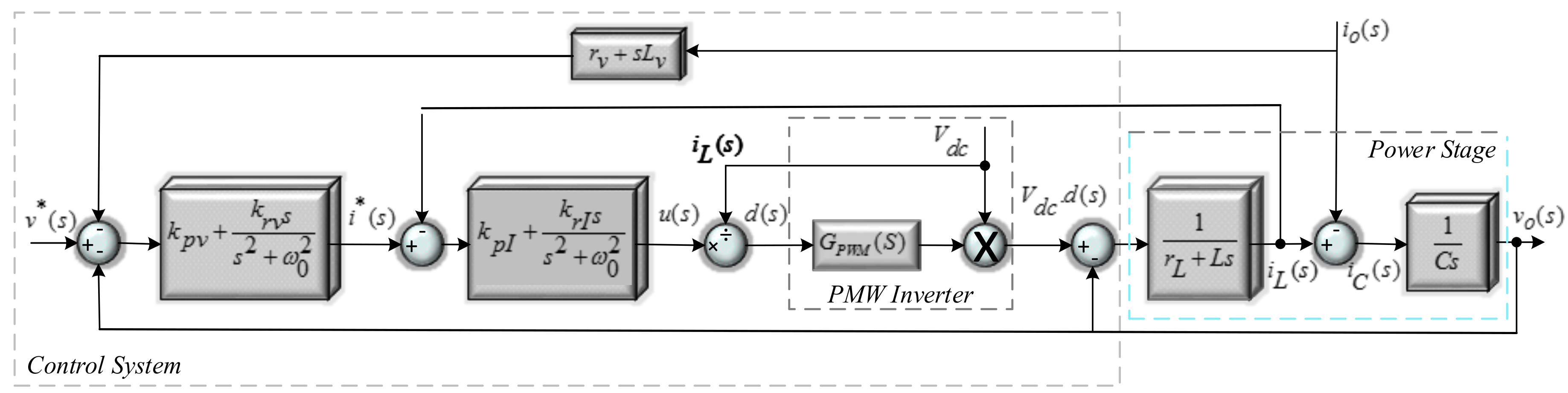
Proportional–Resonant (PR) Controllers of Voltage and Current
The PR current controllers based on stationary reference frames are commonly suitable to manage the voltage and current [
35]. In this study, the PR voltage and current controllers are used, as represented by Equations (8) and (9).
where
(
) and
(
) are the proportional and resonant factors of the voltage and current controller, respectively.
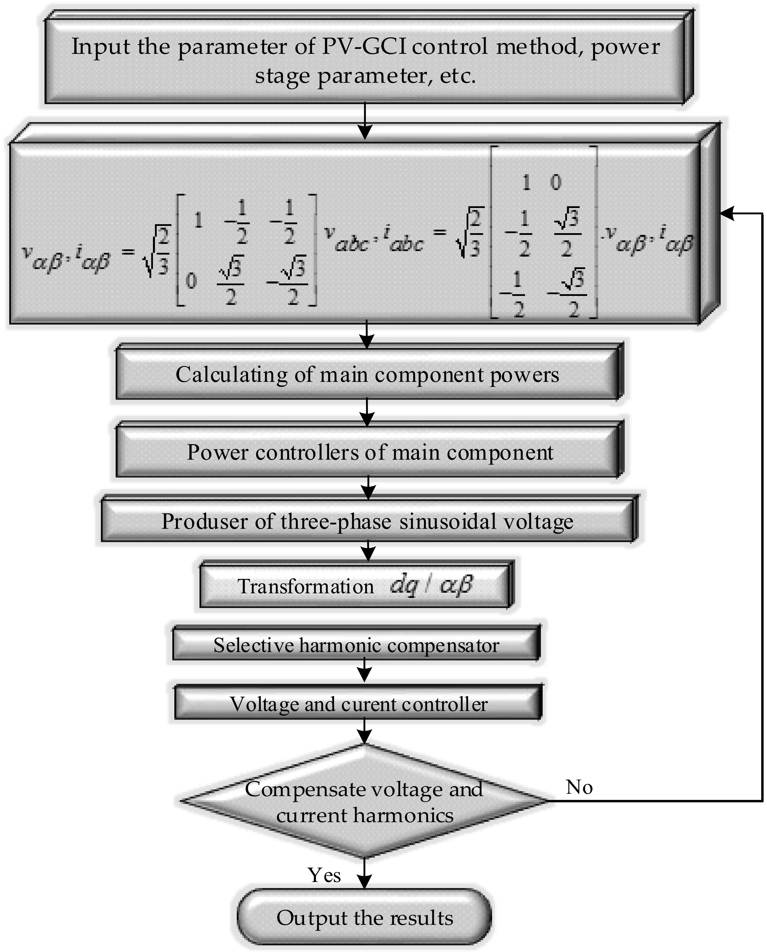
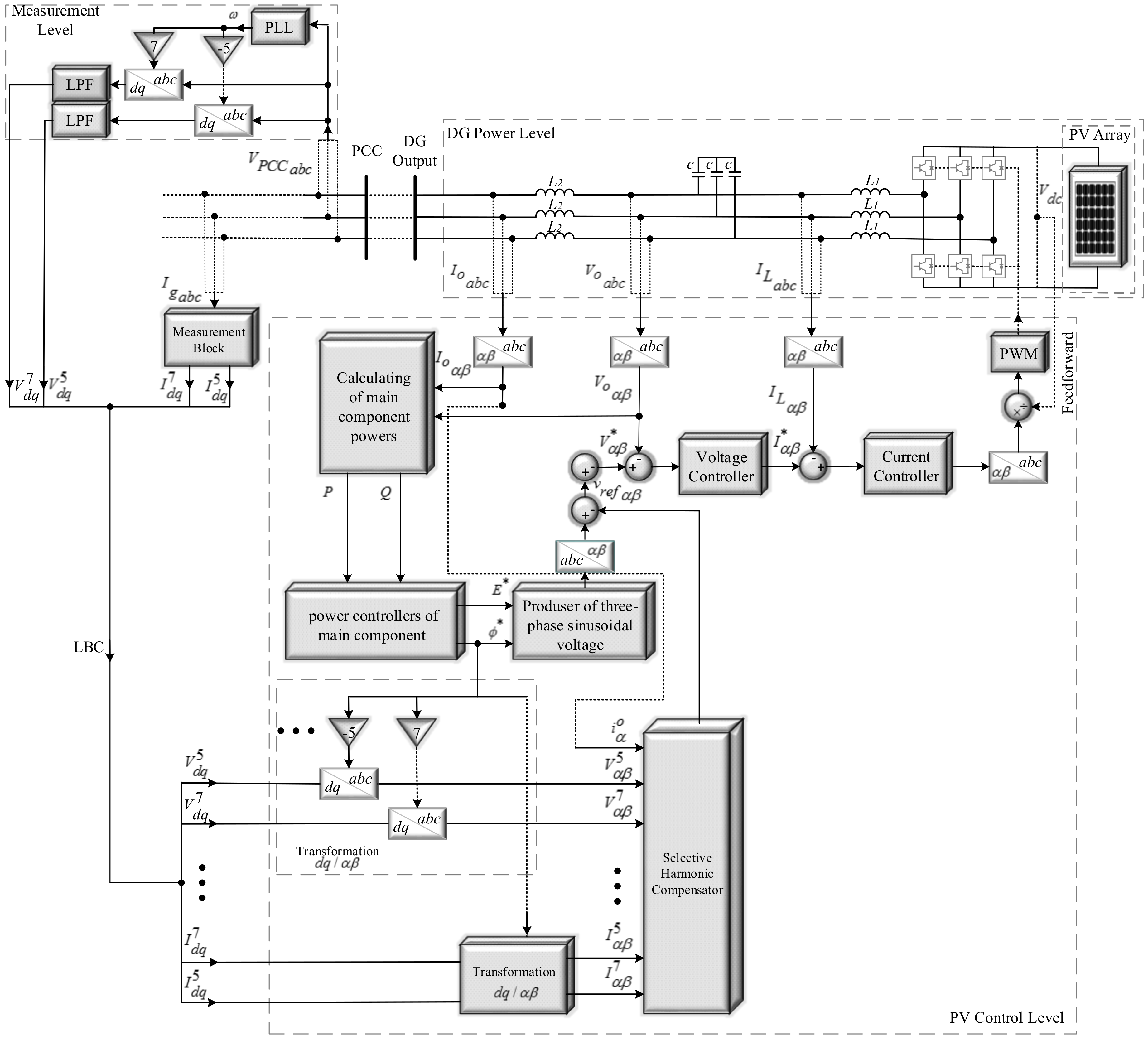
3. Proposed Control Method
Figure 2 shows the flowchart of the proposed control method of the PV grid-connected inverter. The main blocks of the method are discussed as follows. The computation starts with the parameter of PV-GCI control method, power stage parameter, and electrical system parameters. The parameters of the power stage parameter consist of the DC-link voltage, LCL-filter, nonlinear load tie lines, distribution lines, and also PV-GCI control parameters, which include power controllers and voltage/current controllers.
Figure 3 shows a block diagram of the flexible proposed control method for a PV three-phase GCI. The system was performed in two separate parts. First, the power stage of a DG, which was comprised of an LCL filter, a three-phase inverter, and a DC link like PV Module. Second, the proposed controller part was modeled by means of the selective harmonic compensator theory. By controlling the instantaneous filter inductor current (
) in
Figure 3, which is controlled by a current controller, the influx of the load current on the control system performance is properly rejected [
15].
Certain controllers, namely, the control method of PV, are implemented in reference frame to adjust the grid currents in the reference frame.
In the “photovoltaic local adjuster” block, the reference of the DG output voltage in the frame was given by virtual impedance loop, compensation effort adjuster, and power adjusters. At this point, as indicated by *vαβ and the instantaneous measured output voltage (), the reference current () was produced.
Contrarily, the LC filter inductor current was estimated and transformed to the frame and the desired controlled signals were used in the Pulse Width Modulator (PWM) process to produce the changing signals for the PV-GCI.
The Phase Locked Loop (PLL) is widely used for GCI to obtain the grid synchronization information, and its dynamic characteristics have an effect on the stability of the system. The DC components (average values of
p and
q) are fundamental positive sequence active and reactive powers that can be extracted using Low-Pass filters (LPFs) [
36]. The DC-link voltage controller provides the Alternating Current (AC) active power reference. The AC reference is then determined by active and reactive power references and the AC voltage angle. The fixed DC link voltage is definitely greater than peak values of AC voltage. Hence, regulating DC bus voltage by controlling
current of DC/AC converter and regulating Maximum Power Point Tracking (MPPT) by controlling input of DC/DC converter will reduce the complexity of circuitry of a commercial grid-connected PV system. Controlling the DC bus by regulating
current of DC/AC inverter is the best solution to maintain high dynamic response on the AC side. Hence, a PV system designed to provide
in proposed control method.
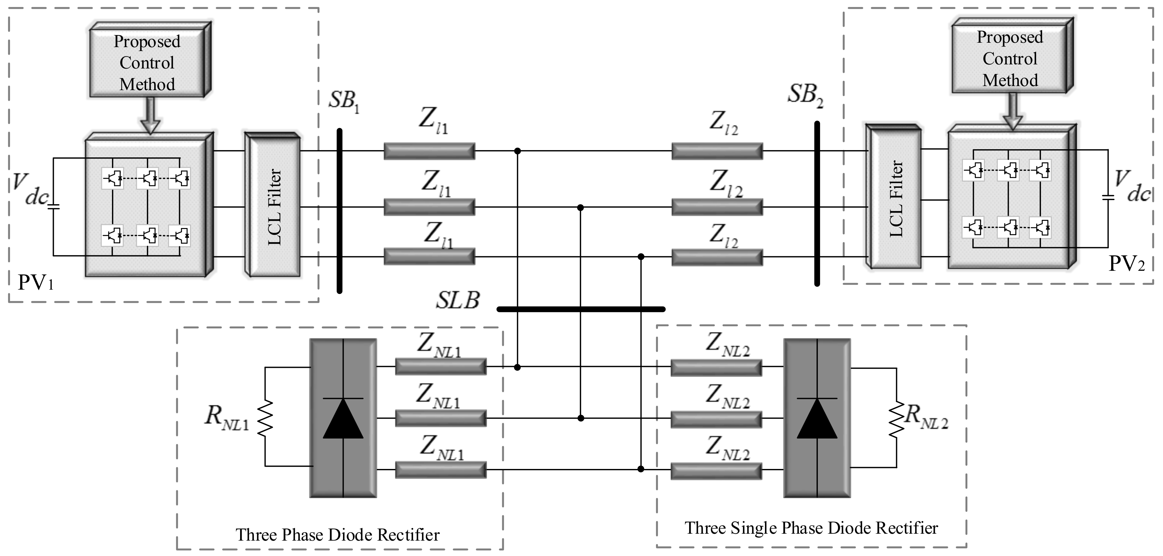
4. Simulation Result
As shows in
Figure 5, an MG with two PV was considered. The nominal power of PV1 and PV2 was the same. Therefore, the parameters of PV1 and PV2 can be adjusted based on their nominal power. Stability can also be analyzed for PV1 and PV2, and similar results can be achieved [
37]. In this regard, this described how to control the droop controllers of the power control.
4.1. Improved Droop Control Method
Most of previous research only reported the implementation of DGs for the injection of active and reactive power into the grid. In the current work, the objectives of GCI is to improve the control strategy for a three-phase GCI of distributed generation sources such as PV. The GCI structure consists of two main parts: The power control part, and the harmonic current and voltage compensation part.
The DC-link voltage of the proposed method is given by:
where
D is average grid voltage approximation,
C is DC-link capacitance.
A and
B is given by:
where
L is AC filter inductance,
is AC grid current and
is AC grid voltage. The three-phase voltages are measured with respect to an artificial voltage
, which is calculated as follows:
where
,
and
are three-phase grid voltages,
is rated angular frequency and
is peak voltage. The PV-GCI that is connected to the grid through the impedance
. The following characteristics were applied to control
and
in the microgrid that was connected to the main grid:
In these equations, and are the reference values of powers, and and are the integral coefficient of active and reactive powers, respectively. Hence, and are the proportion coefficient of active and reactive powers, respectively. Furthermore, E is the phase root-mean-square (rms) value of the PV inverter Fundamental Positive Sequence (FPS) output voltage, represents the grid phase rms voltage, is the load angle, and and are the magnitude and the phase of the impedance, respectively.
Equation (17) acted as a PI controller for voltage with the aim of bringing injection reactive power by the PV to the reference value. Meanwhile, Equation (16), acted as a proportional-derivative controller for the frequency. In fact, since all systems have the same frequency, and there was no frequency error, integral coefficient (zero steady-state error) was not required for following the reference active power.
can be determined in a similar manner to the maximum value of power produced by the original source of PV. For example, MPPT can be used to determine
(even in islanded mode) in the case of a solar system. Additionally,
can be set as zero in order to achieve unity power factor or a positive value to support the reactive power of the network. The
and
can also be determined by a central controller of the microgrid. As explained in Reference [
33], the instantaneous values of active and reactive powers can be writen according to the Equations (20) and (21):
Thus, Equations (20) and (21) can be modified as follows to calculate instantaneous FPS active and reactive powers, respectively:
Furthermore, according to the aforementioned explanations, Equation (24) can be applied for calculation of instantaneous fundamental negative-sequence reactive power in Equation (24):
The FNS reactive power and
LPF(
s) can be expressed by the following Equations (25) and (26) respectively:
where
is the laplace variable, LPFs is transfer function of LPF, and
is cutoff frequency of LPFs.
Using LPF in Equation (25) improves the stability of unbalance compensation by preventing the sudden change of
as aresult of compensation. Finally, the THD of the output current of the inverter can be obtained using Equation (27).
where
is the RMS current of the nth harmonic, and
is the fundamental frequency.
The THD was mainly affected by the output impedance at the harmonic frequencies. Therefore, it is feasible to optimize the design of the output impedance at higher frequencies to minimize the THD of the output voltage and current. It can be achieved without affecting the impedance at the fundamental frequency.
4.2. Current Compensation
The simulation results were obtained using the Matlab/Simulink software to verify the effectiveness of the suggested control strategy shown in
Figure 5.
As shown in
Figure 5, the rated voltage and frequency are considered to be 230 V and 50 Hz, respectively. The system also consisted of twin Nonlinear Loads (NLLs) including three-phase diode rectifier as well as three unbalanced single-phase diode rectifiers generating the bent wave structure. The nonlinear loads are responsible for producing the distorted waveforms [
38,
39]. A proposed control methods were applied to PVs and the values of the three-phase power band and control system are presented in
Table 1 and
Table 2, respectively.
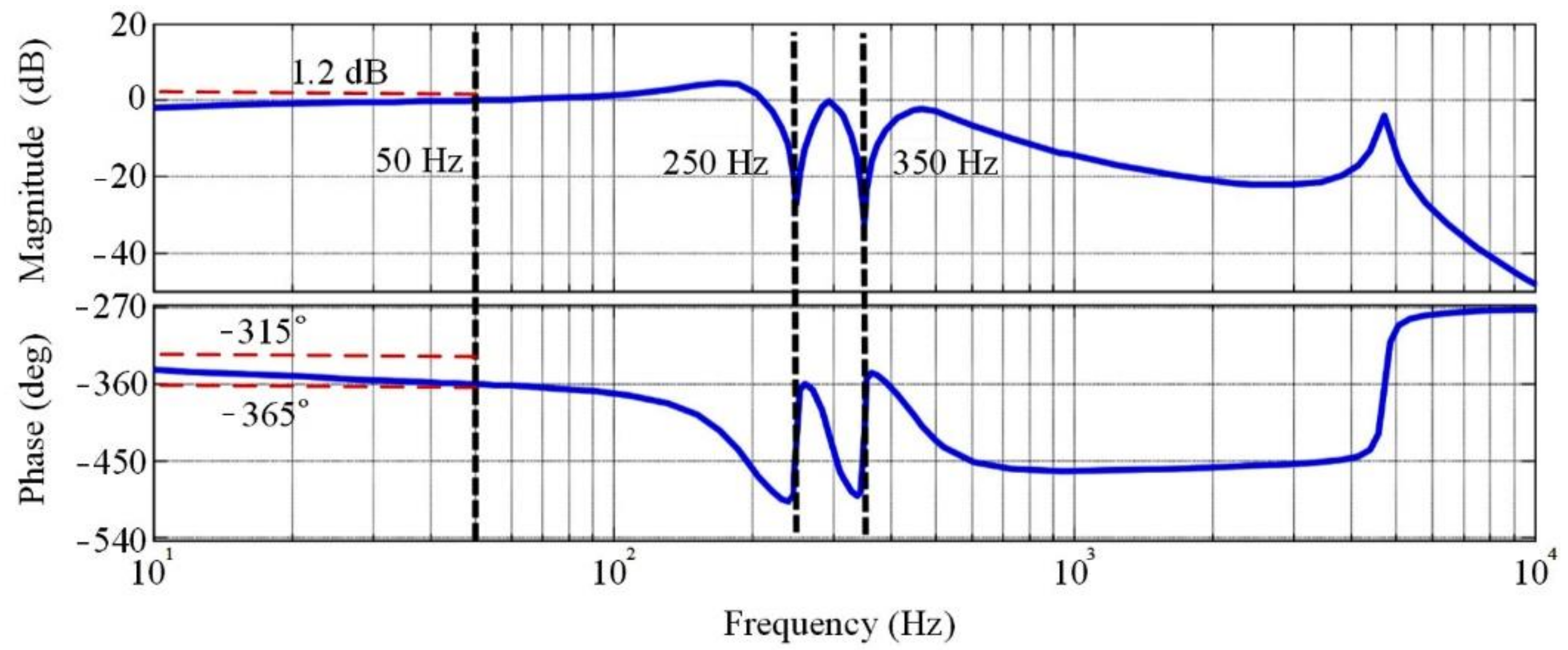
Table 1 lists the positive and the negative-sequence Bode plots of
and
Table 2 lists the positive and the negative-sequence Bode diagrams of
, which were considered as the power stage and PV-GCI control parameters.
Figure 5 shows the magnitude of
for positive and negative sequences. Where
is output impedance and can be extracted:
In this system, one set of phasors has the same phase sequence as the system. Furthermore, the positive and negative sequences can usually be seen in the opposite phase. The positive sequences are needed for unity and negative sequences needed to zero.
Bode diagrams of the magnitude and
are compared in
Figure 6. Moreover, the phase angle of 5th and 7th voltages and currents harmonic components are zero. Thus, the gain and the phase angle of the closed-loop transfer function are unity and zero, respectively. Hence, voltage references are used to provide proper tracking.
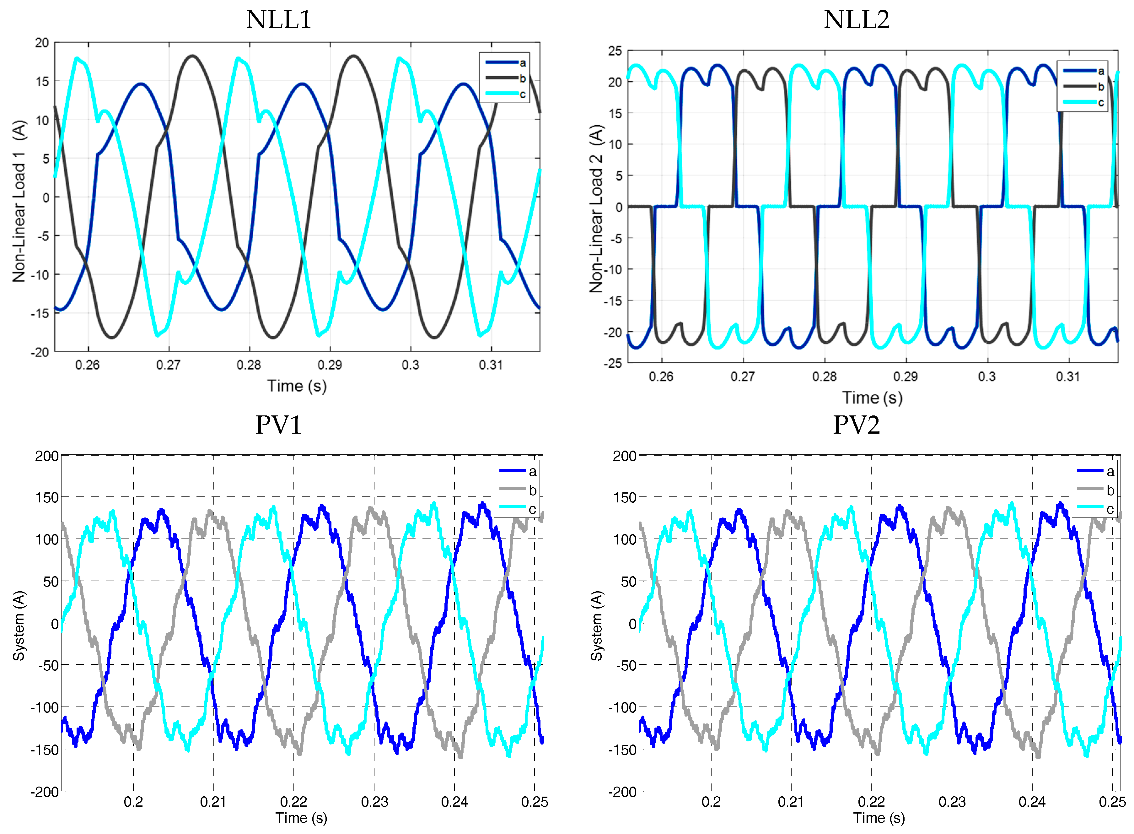
The NLLs including GCI resulted to nonlinear system current and unbalanced which need the insertion of harmonic currents added to MG and grid. The uncompensated nonlinear loads and DGs current wave structures also displayed by
Figure 7.
This figure shows the currents NLL1 and NLL2 and PV1 and PV2, equipped without any compensation devices, which is connected alone to the microgrid. The THD of the current is 5.86% (NLL1), 17.51% (NLL2), 27.41% (PV1), and 27.41% (PV2), respectively. The precompensation and post-compensation waveforms of PV1 and PV2 three-phase output currents are depicted in
Figure 8.
For all simulations, the results of using the proposed control method are compared with those using the control method of UPQC and APFs.
According to the IEEE standards, the current total harmonic distortion should be maintained below 5%.
Figure 8 displays the wave structures of the system currents inserted by the GCI in the case of PVs and nonlinear loads without particular filters working. Prior to proposed control method being switched in, the system current is unbalanced due to harmonics contents. The THDs of NLL1, NLL2, PV1, and PV2 are 0.12%, 0.17%, 0.09%, and 0.08%, respectively. Apparently, the proposed compensation method works by rectifying the bent.
4.3. Voltage Compensation
Figure 5 is also considered as a grid-connected system to test voltage compensation. The power and control system parameters are listed as
Table 1 and
Table 2 respectively. The switching frequency for the grid-connected inverter is set to 10 Hz. According to
Figure 5, two nonlinear loads can cause a harmonic voltage in the microgrid, this ultimately leads to an imbalance in the microgrid. The balanced three-phase line is connected at the PCC point. According to the figure, zl1 and zl2 denote the distribution lines between PVs and PCC. The voltage compensation to balance voltage starts at
t = 0.1 s. Voltage Unbalance Factor (VUF) is adjusted up to 0.5%.
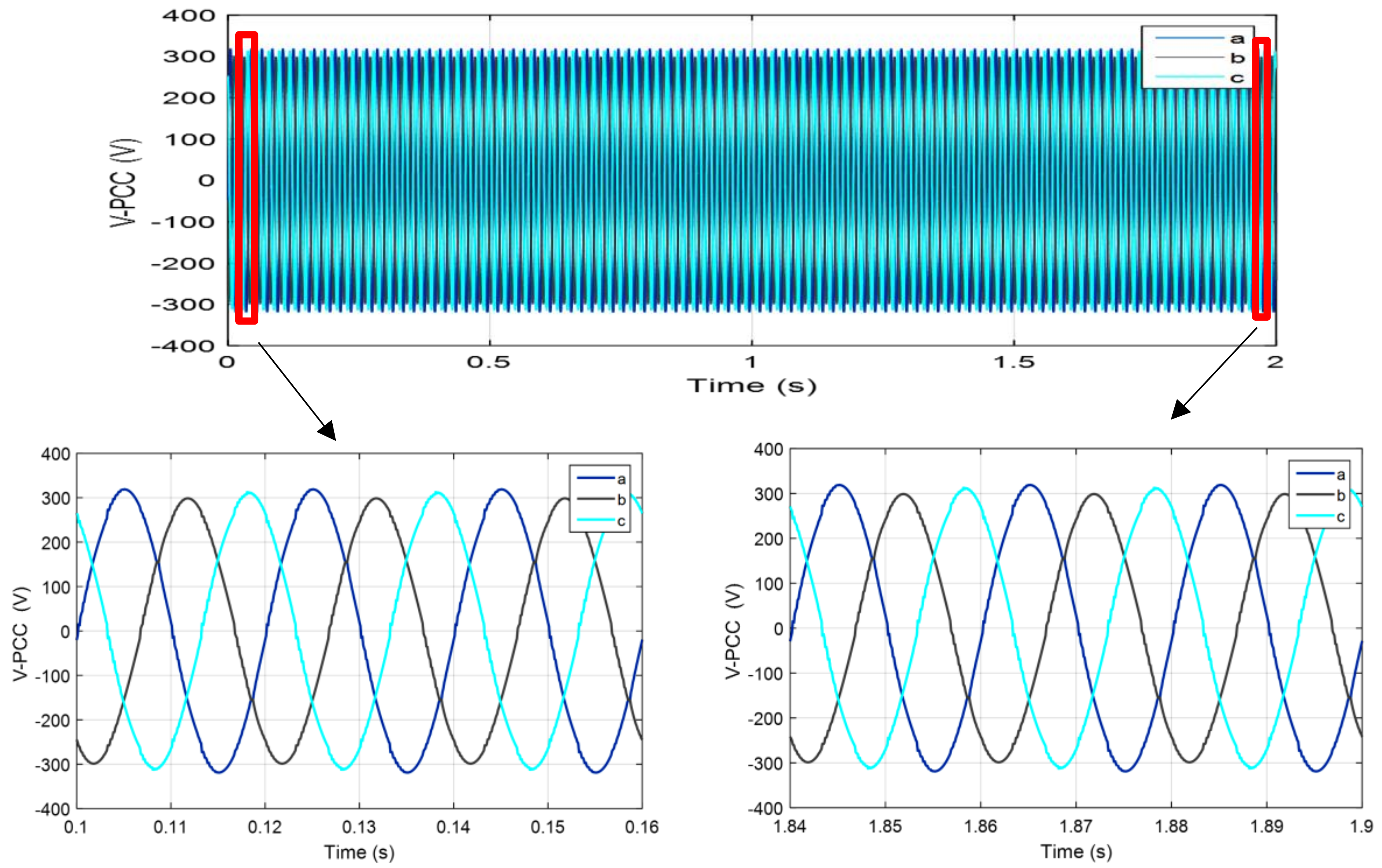
The three-phase output voltages of the grid-connected unit under varying unbalanced load changes, with the conventional control strategy, is depicted in
Figure 9. This figure also shows the transient load voltages as zoomed figures. As can be observed from this figure, the load voltage in phase ‘a’ and ‘c’ are increased by at least 3 line cycles unbalanced due to the inclusion of the line-to-line load between phase ‘a’ and ‘c’. A large distortion voltage is observed in the output voltages with this control strategy; however, it is restored with a slow transient response. Afterwards, the connected load between phase ‘c’ and the neutral line is changed. Consequently, the voltage in phase ‘c’ is gradually increased. Similarly, a unbalanced waveform in the load voltages, and is restored slowly because of the sudden load change. As can be seen from the zoomed figure, the load disconnection leads to unequal voltage values on three-phases. Nevertheless, the output voltage values are restored with a slow transient response.
The PLL is taken into account in the impedance model of the inverter to analyze the impact of PLL on the system, and evaluate the stability of the GCI system. The
frame coincides with the controller
system in a steady state. If there are perturbations in the grid voltage, an angle exists between the two frames due to the PLL dynamics, which will have an impact on the system stability. The transfer function matrix from system
frames to controller
frames can be expressed by
.
The Voltage Unbalance Factor (VUF) at the PCC point follows the reference value properly and defined as follows, is considered as the index of unbalance (40):
where the
is the rms values of the negative of the DG output voltage and the
is the rms values of the positive of the DG output voltage.
Besides this, the quality of the PCC voltage is improved by PVs output voltage disruption. On the other hand, due to the low impedance of the line between PV2 and PCC, VUF is slightly increased. The negative sequence voltages are observed in phase at the PCC point and the PVs terminal. Accordingly, the negative sequence voltage of the PCC is reduced by increasing the negative sequence of the PV output voltage. In addition, in order to show the imbalance compensation, the three-phase output voltages at the PCC before compensation shown in
Figure 9.
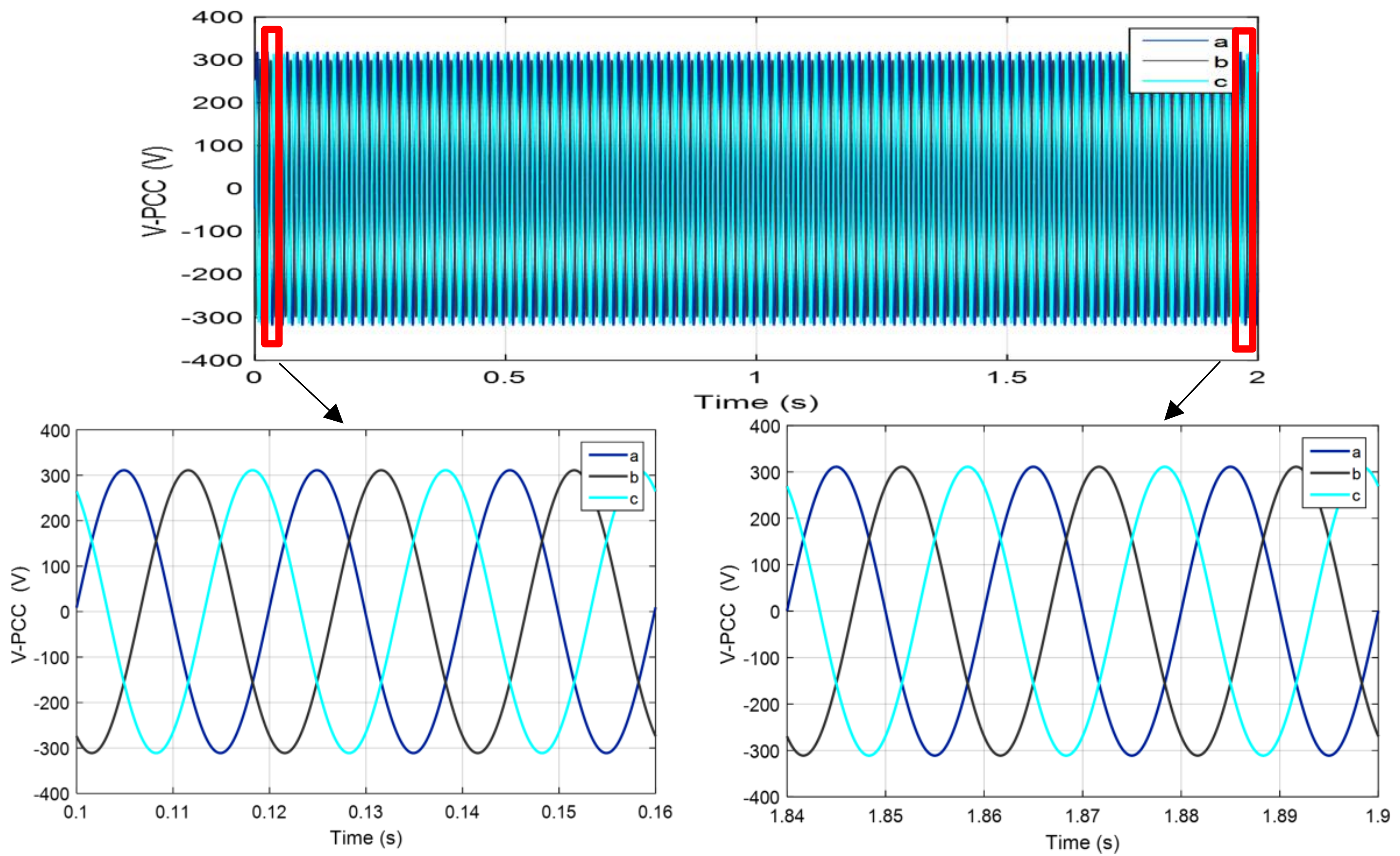
The harmonic value of the voltage is 5.73%. The output of the PV2 voltage is similar to PV1. As it is observed after the compensation, while the PV output voltage is unstable, the voltage imbalance at the PCC point is reduced effectively.
The output voltages of PV1 and PV2, equipped with the proposed control method, are shown in
Figure 10. The balanced voltage is shown as zoomed figures. As can be observed from this figure, the three-phase output voltage is sharply increased due to the inclusion of the three-phase unbalanced load. Afterwards, the output voltage rapidly changes as a consequence of the connection of the three-phase load between phase ‘c’ and the neutral. It is surprising to see that the output voltages of the PV1 and PV2 remain balanced under all unbalanced load changes. Comparing the two PV waveforms, it can be seen that both PVs have the ability to provide balanced output voltages under unbalanced load situations, even when they have to supply a three-phase load in the grid-connected microgrid.
Based on
Figure 10, the voltage THD is reduced from 5.73% to 0.3%, which is approved by the IEEE-519 standard.
Finally, according to Reference [
29], in addition to the current compensation, voltage compensation is also carried out in this paper so that in Reference [
29], only harmonic current compensation is implemented. Therefore, according to the results, the proposed control method is capable of harmonic compensation and the simultaneous unbalance of voltage and current in the presence of nonlinear loads in the microgrid.
The next step is to develop a control method to compensate for other harmonic current and voltage problems at the presence of larger nonlinear loads and more distributed generation sources and also the other PCC voltage power quality problems such as voltage sags.


 and
and 


