Article

Determining Division Location for Sectional Wind Turbine Blades

1
School of Materials Science and Engineering, Wuhan University of Technology, Wuhan 430070, China
2
National Energy Wind Turbine Blade R&D Center, Institute of Engineering Thermophysics, Chinese Academy of Sciences, Beijing 100190, China
*
Authors to whom correspondence should be addressed.
Energies 2017, 10(9), 1404; https://doi.org/10.3390/en10091404
Submission received: 22 July 2017 / Revised: 17 August 2017 / Accepted: 7 September 2017 / Published: 14 September 2017
(This article belongs to the Special Issue Wind Turbine Loads and Wind Plant Performance)

Abstract

:
Sectional wind turbine blades, by dividing an intact blade into multiple segments, have the advantage of being easy to handle and transport. To determine a suitable blade division location, this study was performed to clarify some crucial aspects and challenges for sectional blades. This paper proposes a method to estimate the effects of the location of the blade division on structural, manufacturing, and assembling performance of sectional blades. The advantage of this method is the ease of the assessment process, since it can be performed at an early stage of blade design, where only the aerodynamic profile, mass density and stiffness distribution, and service fatigue loads of original blades are essential. A case study with the proposed method was carried out based on a 38-meter commercial blade. Results show that the best position for the division of sectional blades is located 20% from the blade root by balancing the three aspects listed above. The key approaches to reduce additional increases in stiffness and weight of sectional blades are related to improving the fatigue strength and the choice of low-modulus materials for connecting bolts. The effects of the division location on assembling accessibility and natural frequencies of scaled sectional blades are consistent with the basic sectional blade. Unfavorable effects occur when up-scaling the diameter of the bolts; and, harsh external loads on the connections have negative effects on the application of sectional blades with larger wind turbines. In this regard, lightweight design is indispensable to reduce bolt stress.

1. Introduction

Amongst all the clean and renewable energies, wind energy has been a promising candidate to replace conventional fossil energy, due to availability and relative low cost. Driven by technological innovations and low-cost energy demand, wind turbine (WT) installation capacity has been growing quickly for two decades; blades larger than 50 m are expected to be the mainstream for large-scale WTs [1,2]. As of 2016, the longest commercial blade extended to 88.4 m in length [3]. However, transporting long blades may require police assistance, disconnecting and reconnecting traffic components, decrease the perceived value of wind energy, and even increase the damage risk of the blades [4,5]. Griffin indicated that blades 45.7–48.4 m in length are the transition point where longer blades tend to visibly increase the costs of transportation and handling problems [6]. In addition, the length constraints of goods transported by truck and rail are 53 m and 62 m, respectively. In the case where the route to the wind farm is difficult, multiple handlings between different transportation vehicles are often required, causing the cost of blade transportation to increase sharply. Meanwhile, manufacturing long blades would be beset with difficulties without special tooling and molding equipment. In fact, the cost of wind energy is not necessarily reduced by upscaling WTs based on current technology [7,8,9], due to size effects such as expensive transportation and logistics, overloads, and mass increase [8,9]. Sectional blades, as an innovative technique, are the key solution to transportation issues and to help reduce the cost of wind energy [5]. Moreover, records show that the cases of blades in service are most often damaged by lightning strikes, which ruins the blade tips. The outer sections of blades can be replaced at a lower cost and under easier assembly conditions than the entire blade. Moreover, blade families can be easily built by designing the blade tip section to follow various wind farms and turbines based on the current inner section of the blade [10,11].
Sectional WT blades have been developed for more than 30 years [12]. During this period, sectional blades attracted interest from engineers and researchers, and many patents related to innovative connection design and configuration of sectional blades were created [10], but mass commercial application of sectional blades has not yet been achieved due to technology and cost limitations [5,7,13]. In spite of the benefits in the transportation of large WTs using sectional blades, undesired cost increases, feasible and accessible connections, and the effects of blade separation on overall structural performance are major obstacles [10,12,13,14,15]. Once the intact blade is cut into multiple segments, the continuous fibers of the composite blades, which are used to be the load carrying media, break and are unable to sustain the same loads at the terminals as before. As a result, additional materials or structures ought to be used to compensate for the reduction in stress transfer, and structural reinforcements around the blade connection then causes stress concentration as well. On-site assembling of different segments and maintenance of blades would require sufficient operation space. Therefore, comprehensive estimates of the various aspects discussed above have to be solved during the early stages of sectional blade design, and a trade-off decision then has to be made to determine the division location.
There are several research institutes and corporations that have completed practical studies on sectional blades [11,12,13,14,15,16,17,18,19]. The general results of these studies are outlined in Table 1.
The concept of the sectional blade was first used on a DEBRA WT with T-bolt connections in 1982. The blade was divided into two segments with equal length, so that an 11.58 m blade could be easily packed and transported within a 6 m uniform container [12]. Dutton et al. [14] investigated the structural performance of sectional blades with tube connections based on an LM 13.4 m commercial blade; the division location was 4.5 m from the blade root. Results of extreme and fatigue loading tests met the requirements for the prototype blade. Dutton et al. [13] tested a sectional blade with T-bolts based on the LM 23.3 blade, and the division location for larger sectional blades was determined at 7.3 m from the blade root, rather than at the midpoint of 11.5 m. The results showed that the sectional blade fulfilled the fatigue requirements. In addition, Vionis et al. [11,15] first studied sectional blades based on a MW-class blade whose length was 29.65 m, without considering the 4.5 m tip section used for braking; the rest of the inner section was designed to be nearly equally divided so that the final division location was 12.4 m from the blade root. When a prototype blade was tested according to the IEC-61400-23 standard, the bolt connection failed to bear the fatigue loads, and a large number of bolts, one after another, broke during the test. GAMESA developed a commercial sectional blade with a length of 62.5 m in 2010 [16], for which the separation of the blade was determined near the mid-point of the blade, 32 m from the blade root, taking utmost advantage of transportation accessibility with equal-length sections. In 2007, ENERCON [17] installed their multi-megawatt WTs with sectional blades. The blades uniquely consisted of a 24 m steel inner part and a 35 m composite outer part. More recently, ENERCON developed a 56 m sectional blade with a relatively shorter inner segment (12 m) compared to the previous sectional blades [18], fabricating the inner part of the sectional blade with glass fiber composites instead of steel. Qin [19] considered 18 m as the division location for a 38 m sectional blade, due to the overall consideration of composite layups and operation space for the maintenance of sectional blades. The blade performed successfully under 120% of the design loads in all four directions during extremely static tests in 2015, while the fatigue test has not yet been performed until now.
Meanwhile, GAMESA [7] completed the preliminary design of a 42.5 m sectional blade with a 15 m inner segment. They considered the impact of blade separation on natural frequencies as being negligible when the separation was located in the range of 10–20% of the radius from the blade root. Saenz [10] took the smooth ratio of flap moment to thickness as the approximate rule for determining the division location for sectional blades. Nanami [20] chose the midpoint as the division location for a case study of an 80 m sectional blade. Bhat [21] decided that the mid-point on a 47 m sectional blade was best for the division location, based on modal shape, bending deflection, and fatigue damage of the original non-divided blade. Unfortunately, the impacts of blade connection on structural responses were not investigated in that analysis. Saldanha [22] considered the ratio of deflection slope to length under test loads as the criterion for the division location. Xu [23] selected 16 m as the division location for a 46.5 m blade for loads while considering manufacturing and the ratio of thickness to chord, but without any more comments.
From the previous literature, it can be summarized that (i) the mechanical connection with bolted joints is the best load transfer media for sectional blades, and bolt failure is the key challenge for the use of sectional blades, (ii) the blades targeted by studies have become increasingly longer, which involve more severe transportation problems, and (iii) the division location of sectional blades varies with the many concerns of blade designers. Obviously, there is no consensus on the preferable position for blade separation. However, the location of a division on a sectional blade is vital and predictive; it affects the multiple considerations for the design of WT blades, such as blade mass and cost, dynamic vibration, connection strength, manufacturing, assembly, and maintenance. Since the costs of the blade are tightly associated with connection configuration and detailed structural constitution, the effects of the division location on the cost increase of sectional blades will finally be discussed. Natural vibration responses, connection strength, and assembling accessibility are crucial for the engineering design of sectional blades [7,10,12,13,15,19], and will be considered the main estimation factors in the following analysis because natural frequencies of the WT blade are related to the dynamic WT responses, and the design regulation requirements must be fulfilled. Improving connection strength and assembling accessibility are two key factors for most patents for the use of sectional blades with the intent of putting forward new joint configurations.
Based on previous studies and our experience with designing and manufacturing sectional blades [19], our work presents a brief method for determining the division location for sectional blades by evaluating the effects of the following three aspects on connection performance of sectional blades: natural frequencies, connection strength, and assembling accessibility. A practical case study was performed to clarify the optimal division location for sectional blades, and an upscaling study was conducted to analyze the demands and trends in larger sectional WT blades. This paper provides clear insight on the span location selection for large sectional WT blades from a technological view, highlights the challenges, and offers some recommendations for larger sectional WT blades.
This article is organized as follows: firstly, the influences of associated factors are illustrated, and a method to evaluate the division location on the performance of sectional blades is proposed. Then, a case study analyzing the optimal division location for a 38 m original blade, which has been mostly installed, is reported. Finally, the effects and prospective challenges of sectional blades on larger WTs are evaluated using an analytic upscaling principle and by examining the constraints on transportation vehicles.

2. Evaluation of Connection Performance of Sectional Blades

2.1. Connection Strength for Sectional Blades

After decades of evolution, most modern WT blades have a similar structural configuration. Figure 1 illustrates the cross section of a typical WT blade, which consists of outer surface shells, involving pressure and suction surfaces, and inner shear webs. The shear webs mainly carry shear stress, and the direct stress of WT blades is mainly distributed to the outer surface shells. Literature review reveals that a mechanical connection with a bolted joint dominates the load transfer for sectional blades, and bolt failure is the key challenge of sectional blade applications [10,13,15,17,20,23,24,25]. To improve the connection strength of sectional blades, more bolts are generally distributed along the entire surface shell of sectional blades at the division section. Since bending moments, which are mostly supported by surface shells, are the dominant loads for large horizontal-axis WT blades [26,27], this design can take advantage of assembly space to strengthen the connection to a maximum extent. Meanwhile, bolt arrangement to form a closed circle of sectional blades can enhance torsion stiffness [28] and avoid the detrimental prying effect of the bolted joint [29]. This study assumes that blade segments are connected by bolts along the whole of the surface shells. Extreme static and fatigue strength are required to guarantee the structural safety of WT blades according to IEC standards [30]. Previous experimental studies indicated that no sectional blades have ever failed the static test, and the static strength of the bolted joints of sectional blades is less critical; that stress on bolts can be relieved, to some extent, without significant strength degradation by material yield, and the fatigue strength of bolts is comparatively more important for sectional blades. Statistical investigation also determined that most of the pre-stress bolted joint failure was due to large fatigue stress [29]. Therefore, the connection strength of sectional blades would be evaluated on their fatigue performance.
For bolted joints under high dynamic loads, pre-stress bolted joints, which mainly carry axial loads, are preferred to reduce the fluctuating stress of connection bolts [31]. When the bolted joints of sectional blades are committed to axial loads produced by bending moments or centrifugal forces, the loads on the bolts in the axial direction are proportional to external axial loads, according to VDI 2230 guidelines [32]. The load increments of connection bolts depend on the relative stiffness of the bolted joint, which acts as a spring stiffness model. The coefficient is called the load factor, expressed in Equation (1):
= Δ F b Δ F e = n × k b k b + k m .
If the bending effect of the bolted joint is not considered, = k b k b + k m is satisfied with n = 1.
For a specific bolted joint, k b and k m are kept constant regardless of the nonlinear deformation of the bolted joint, due to very large external loads [33,34]. Then, the fatigue loads on the bolts are in line with the axial fatigue loads, as shown in Equation (2):
Δ F f b = × Δ F f e .
The range of fatigue stress imposed by bolts can be easily calculated by external fatigue loads and the cross-section area of the bolt. Pre-tightening of high-strength bolts generates pre-stress, which then is formed as the mean stress of connection bolts. Experimental research has demonstrated that the mean stress has far less impact on the fatigue limits of bolt strength [35] than the classic Goodman correction theory, which indicates the fatigue stress range as the determinant term for strength evaluation of bolt fatigue with different pre-tightening levels.
Assuming that all connection bolts used are identical in standard and type, the blades generally are manufactured with constant thickness laminates near the division (Figure 2).
Firstly, the centroid (O) of the airfoil is derived by integrating the contour line of the airfoil, and the axial stress (z direction) normal to the local section (x–y plane) can then be expressed in Equation (3):
σ z = E ( a y + b x + c ) .
According to classical beam theory [36] the flap-wise and edge-wise bending moments ( M x and M y ) can be expressed by Equations (4) and (5):
M x = a E I x x + b E I x y + c E S x *
M y = a E I x y + b E I y y + c E S y * .
When the beam structure of a blade is subjected to asymmetrical bending moments, the axial stress of the blade-cross section can be formulated by Equation (6):
σ z = M x I y y + M y I x y I x y 2 I x x I y y y + M y I x x + M x I x y I x y 2 I x x I y y x .
Then, the variable ( Δ σ k , A ) b , for estimating the connecting strength of bolts, can be simply expressed by Equation (7):
Δ F f b = Δ σ z × A shell A bolt = A shell A bolt Δ σ z
where A bolt and A shell are considered constant values for the given bolted joint; hence, we can estimate the ranges of fatigue stress of the bolts by indirectly using the fatigue stress ranges of blade shells, and the stress calculation of blade shells under bending moments is stated by Equation (7).
To obtain the stress distribution of blade shells, the calculation process can be performed with the user developed program. Firstly, the equivalent fatigue moment of blades is transformed into a chord coordinate system, and M x and M y are obtained. Then, the discrete points on the blade shells (skin) are equally allocated. Next, a virtual area value is given to every point while ensuring the area value is always kept identical; based on the known points and the area value, I x x , I y y , and I x y can be computed. Through Equation (6), the fatigue stress ranges of the blade shells at every point are obtained, and the maximum stress from the discrete points is identified. This procedure should be repeated to achieve all maximum stress values for all the desired sections for sectional blades. Low stress carried by bolts indicates superior connection strength for sectional blades.

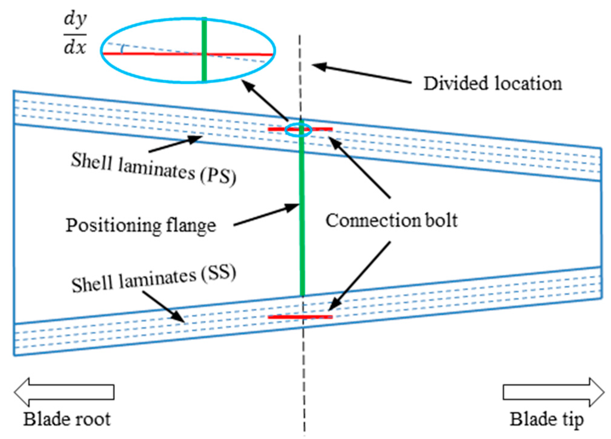
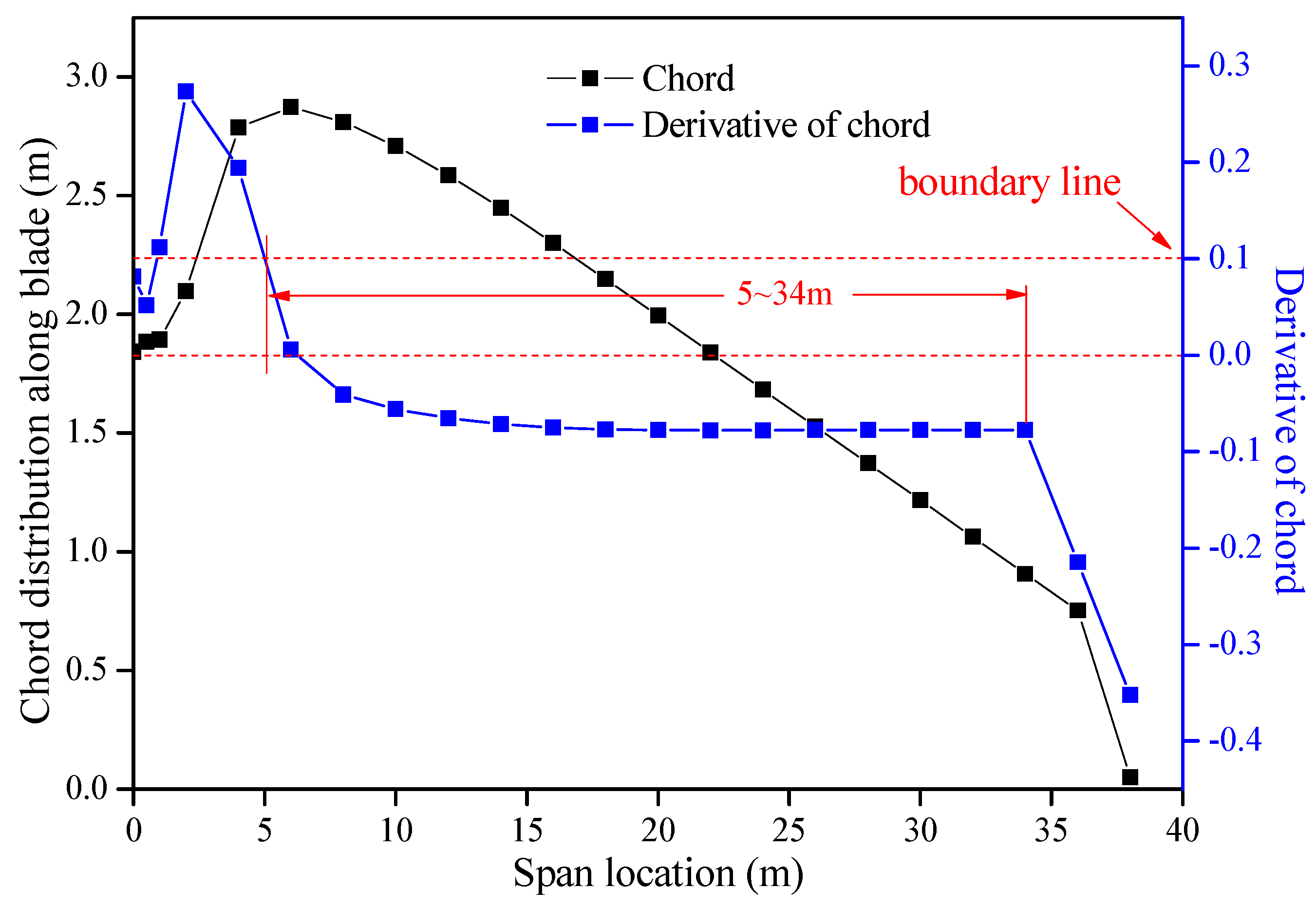
2.2. Manufacturing and Assembling Accessibility for Sectional Blades

The manufacturing and assembling process of sectional blades are key aspects for practical applications. Their feasibility and adoptability are directly related to manufacturing costs and complexity. Nowadays, T-bolts and embedded sleeves dominate connection patterns for large WT blades [37,38]. High-strength connecting bolts for sectional blades mainly bear axial loads, and bolts transfer loads from outer to inner parts of the blades. From the point of view of connection efficiency and the strength of bolts, if the axial direction of the bolts is parallel to the local blade shell, or 0-degree fiber of composite laminates, then the composite layer can be laid down smoothly and a smaller bending effect occurs on the bolts. The bending effect of force transfer has detrimental effects on bonded joints, involving embedded sleeve cohesion, and bolted joints [39,40]. In terms of manufacturing and assembling, a positioning flange exists for manufacturing each section of the blade. Generally, the flange is a flat plate, and the bolt axial direction is vertical to the flange plate. For a conventional tapered blade with chord and thickness reduction along the blade, inevitably there would be an intersection angle between the blade shells and the bolt axis (Figure 3). This would lead to a worsened mechanical performance of the laminates adjacent to bolts due to wrinkle or resin sockets during the molding process. Therefore, when selecting the division location of sectional blades, the slopes d C d x x , d T d x x . of the chord and thickness, respectively, along the blades are taken as main factors for evaluating manufacturing and assembling accessibility, where the chord and thickness of the blades are denoted as C and T, respectively.

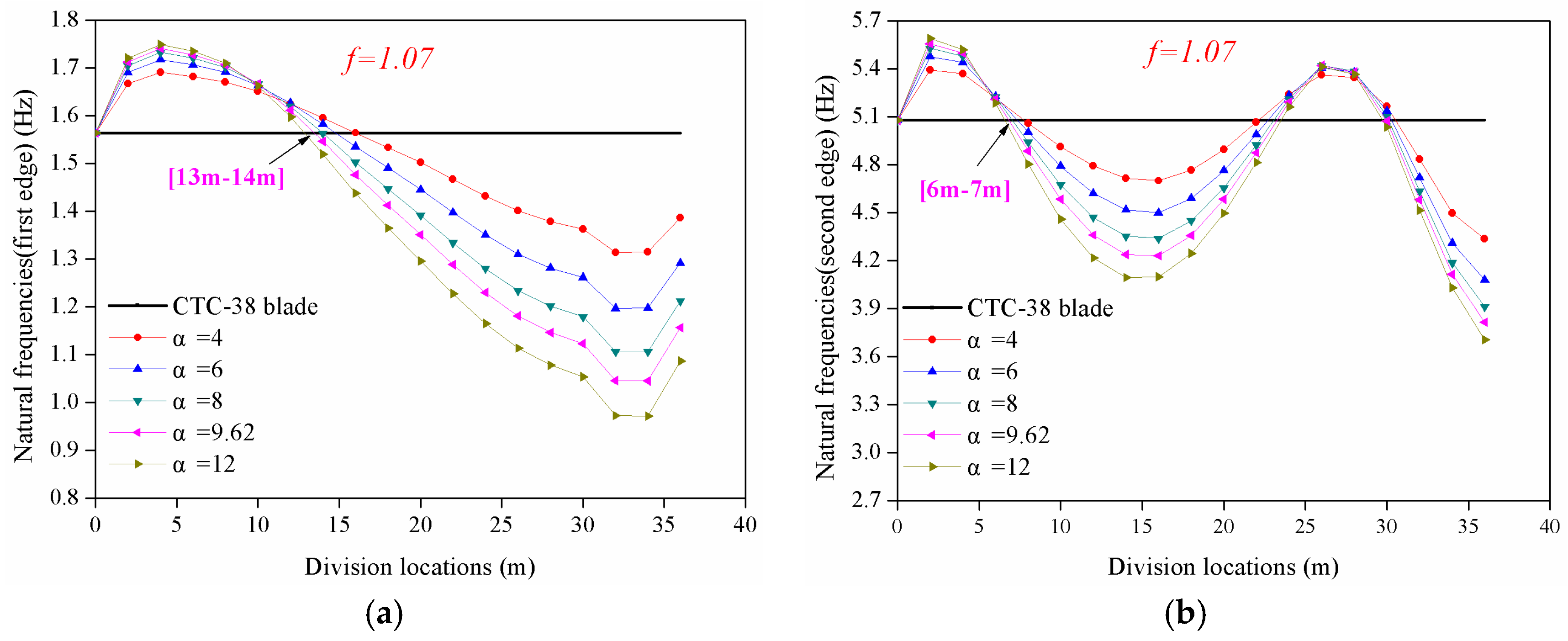
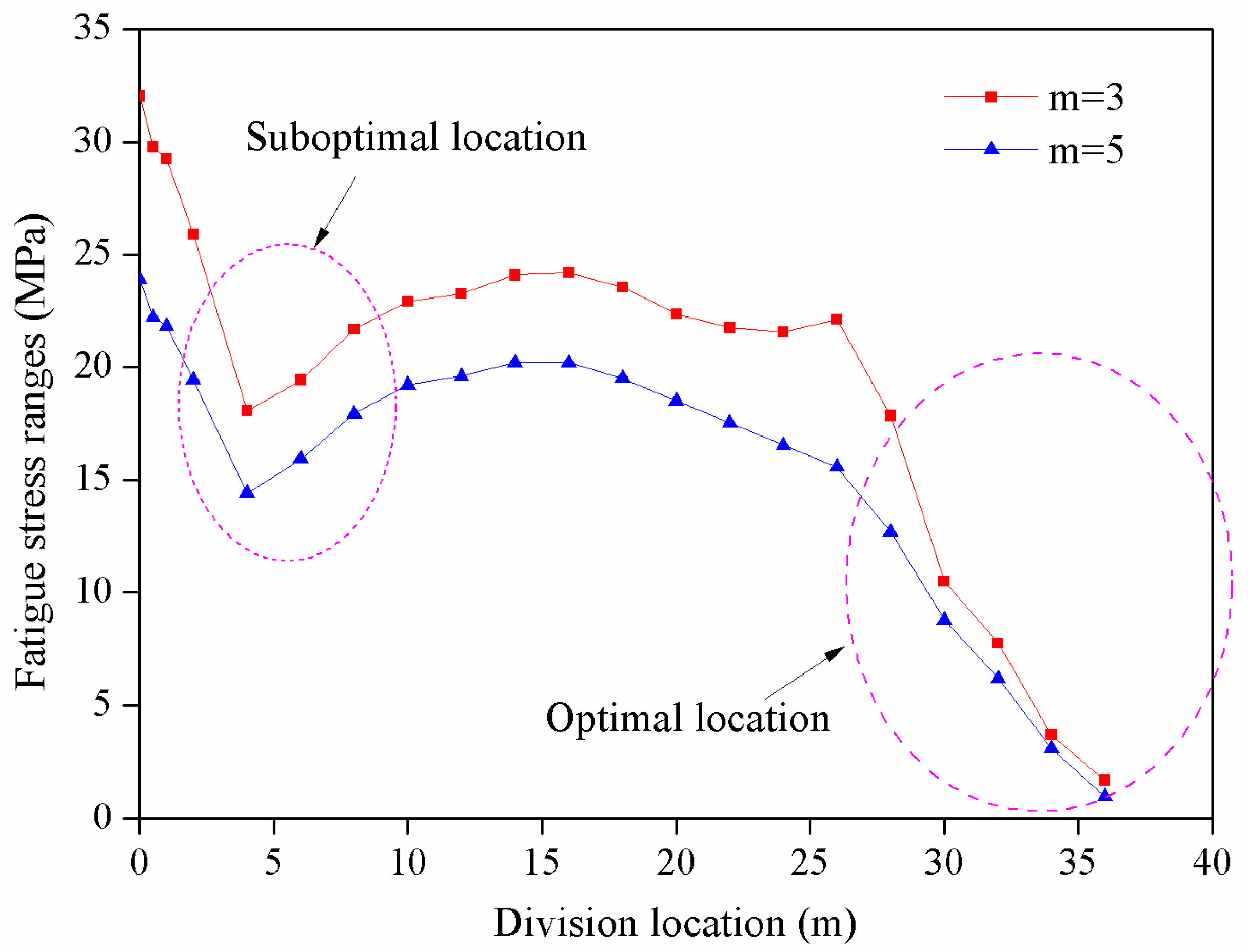
2.3. Division Location Determination by Natural Frequencies of Sectional Blades

2.3.1. Natural Frequencies Calculation

The dynamic response of sectional blades is another aspect that affects the operation of the blades and other components of WTs [26]. To avoid resonance issues, natural frequencies need to be carefully calibrated after dividing the blade. To estimate the natural frequencies at various division locations, this study determined cross-section stiffness and mass density of the sectional blades by scaling those of the original blades at the division sections and then gradually transitioning to the corresponding values of the original blades.
Figure 4 illustrates the distribution of cross-section stiffness and mass density of the original and corresponding sectional blades with blue and dark lines, respectively. If ( E I ) O B and ( M D ) O B of the original blade are known, additional stiffness and mass density should be added around the division location for sectional blades, and the corresponding values at the division location are defined as ( E I ) S B and ( M D ) S B . Simultaneously, the cross-section stiffness and mass density should gradually change around the division location to avoid local stress concentration. The transition region for cross-section stiffness and mass density are considered as the same, and are equally distributed at each side; they change linearly in the region and then arrive at the corresponding values of the original blade beyond the transition region.
With these assumptions, cross-section stiffness and mass density distribution of sectional blades can be obtained for a given stiffness, mass density distribution, and transition region. With the help of our own developed program based on Matlab R2010, natural frequencies of sectional blades can be solved as an eigenvalue problem of the classical beam.
The cross-section bending stiffness of the sectional blade in flap-wise and edge-wise directions are shown in Equations (8) and (9):
( E I x x ) S B = S B E y 2 d x d y = E y 2 d x d y = i = 1 N E e , s A s y i 2 = A s E e , s i = 1 N y i 2
( E I y y ) S B = A s E e , s i = 1 N x i 2 .
The cross-section bending stiffness of the original blade, which is popularly manufactured by fiber-reinforced composite (FRC), in flap-wise and edge-wise directions, are shown in Equations (10) and (11):
( E I x x ) O B = O B E y 2 d x d y = i = 1 N E F R C , o A F R C , o y i 2 = A F R C , o E F R C , o i = 1 N y i 2
( E I y y ) O B = A F R C , o E F R C , o i = 1 N x i 2 .
Combining Equations (8)–(11), the ratio α of cross-section stiffness between the sectional blade and the original blade at division location is shown by Equation (12):
α x = ( E I x x ) S B ( E I x x ) O B = A s E e , s A F R C , o E F R C , o = A b , s A F R C , o × E b E F R C , o × A s E e , s A b , s E b = μ × ω × φ = α y
The terms used to describe α are defined in Equations (13)–(15):
μ = A b , s A F R C , o
ω = E b E F R C , o
φ = A s E e , s A b , s E b .
The cross-section mass density of the original and section blades are shown in Equations (16) and (17):
( M D ) S B = S B ρ d x d y = i = 1 N ρ i A i = ρ e , s A s
( M D ) O B = S B ρ d x d y = i = 1 N ρ i A i = ρ F R C , o A F R C , o .
According to the intrinsic characteristics of modulus and density of FRC and steel materials, we define a term f in Equation (18):
f = ( E I ) S B ( E I ) O B ( M D ) S B ( M D ) O B = ( E A ) S B ( M D ) S B × ( M D ) O B ( E A ) O B = A s E e , s A F R C , o E F R C , o × ρ F R C , o A F R C , o ρ e , s A s = E e , s ρ e , s × ρ F R C , o E F R C , o = E F R C , s Θ F R C , s + E b ( 1 Θ F R C , s ) ρ F R C , s Θ F R C , s + ρ b , s ( 1 Θ F R C , s ) × ρ F R C , o E F R C , o = f ( Θ F R C , s )
where f is the function of Θ F R C , s , and Θ F R C , s varies between 0 and 1. With a given value of E F R C , s ,   E b , ρ F R C , s , and ρ b , s , the f ( Θ F R C , s ) can be determined. Therefore, the cross-section mass density ratio β can be formulated with Equation (19):
β = ( M D ) S B ( M D ) O B = α x ( y ) f ( Θ F R C , s ) .
Since ω and f are easy to determine, the allowable and reasonable values of μ and φ will be deduced in the following sections.

2.3.2. Analysis and Deduction of Parameters μ and φ

Fatigue strength of the bolted joint is a major issue for sectional blades, according to GL guidelines [27]. For a given FRC fabricated by a specific manufacturing method, the short-term strength of the FRC can be obtained through the corresponding experiment, under a symmetrical fatigue loading; and, the fluctuating stress ( Δ σ k , A ) F R C , o for given fatigue cycles can be computed according to S-N relationship formula defined by GL guidelines [27].
Regarding the fluctuating stress ( Δ σ k , A ) b , s of connection bolts, detail category Δ σ k , C is defined with respect to 2 × 10 6 fatigue cycles according to Eurocode 3 [41]. The fluctuating stress ( Δ σ k , A ) b , s of bolts for given fatigue cycles, less than 5 × 10 6 , are computed via Equation (20):
( Δ σ k , A ) b , s = ( 2 × 10 6 N ) 1 3 × Δ σ k , C .
If fatigue cycles are between 5 × 10 6 and 1 × 10 8 , the fluctuating stress ( Δ σ k , A ) b , s of bolts is obtained with Equation (21):
( Δ σ k , A ) b , s = ( 5 × 10 6 N ) 1 5 × ( 2 5 ) 1 3 × Δ σ k , C .
If fatigue cycles are more than 1 × 10 8 , the fluctuating stress ( Δ σ k , A ) b , s of bolts is obtained with Equation (22):
( Δ σ k , A ) b , s = 0.405 Δ σ k , C .
Based on equal fatigue strength of the bolt and FRC, and the considering load factor of the bolted joint, the cross-section area ratio μ , can be expressed in Equation (23):
μ = A b , s A F R C , o = ( Δ σ k , A ) F R C , o ( Δ σ k , A ) b , s .
A single bolted joint can be extracted from the bolted joint group illustrated in Figure 5, where the stiffness of the bolt and clamped members are expressed in Equations (24) and (25):
k b = 0 l k E b A b d x
k m = 0 l k E m A m d x .
Thus, the stiffness of the bolt can be obtained with Equation (26) because of uniform stress distribution in the axial direction. According to the stress distribution of the clamped members beneath the nut, the stiffness would be expressed by Equation (27), including three parts of cone and cylinder areas. Numerical simulation has validated that the assumed 30 degrees was fitted well for most cases (Figure 5b) and adopted for general practical design [42].
k b = A b E b l K
1 k m = 1 k m 1 + 1 k m 2 + 1 k m 3 .
For an ideal case, uniform compression of clamped members under bolt tightening occurs, which increases the stiffness of the upper and lower parts, and they can be expressed with k m 1 and k m 3 shown in Figure 5c, and can be deduced in Equations (28)–(30):
k m 1 k m 1 ;   k m 2 = k m 2 ;   k m 3 k m 3
1 k m = 1 k m 1 + 1 k m 2 + 1 k m 3 1 k m = 1 k m 1 + 1 k m 2 + 1 k m 3
k m k m .
As assumed above, and combining Equations (28)–(30), these yield the following:
k m 1 = A m E m l k 1 ;   k m 2 = A m E m l k 2 ;   k m 3 = A m E m l k 3
1 k m = 1 k m 1 + 1 k m 2 + 1 k m 3 = A m E m l k
= k b k b + k m = A b E b A b E b + A m E m = A b E b A s E s e .
Then, the minimal stiffness ratio φ m i n of the sectional blade to the original blade is computed as follows:
φ = A s E s e A b E b φ m i n = 1 .
For most bolted joints used for sectional blades, the distance of the adjacent bolts D k and the thickness of the clamped members are much less than the axial length of clamped members l k . This design characteristic benefits the initial clamped strain energy to prevent joint loosening and smaller ranges of fatigue stress by bolts [29]. Thus, the ideal value of φ is near φ m i n . In consideration of sound joints, we assume φ to be equal to γ φ m i n in the following analysis. Substituting Equations (13), (23), and (34) into Equation (12), it gives:
α x ( y ) = μ × ω × φ = ( Δ σ k , A ) F R C , o ( Δ σ k , A ) b , s × E b , s E F R C , o × γ = γ × ( Δ σ k , A ) F R C , o ( Δ σ k , A ) b , s × E b , s E F R C , o .
Equation (35) reveals that stiffness increases of sectional blades are mainly affected by fatigue strength and the modulus of bolts rather than the load factor of a bolted joint.

3. Case Study of a Commercial Sectional Blade

To understand the effects of the division location on various performance indicators of sectional blades and to further offer some recommendations for engineering design, a case study of an excellent and typical commercial blade was conducted with the proposed method. The work is based on a 38-meter commercial WT blade (CTC-38), which was designed by CTC Technology of The Netherlands in 2006. Over 1000 CTC-38 blades, with a rated power of 1.5 MW, have been sold and installed. These blades have been in good working condition for the last 10 years. The specifications of the CTC-38 blade along the span are shown in Figure A1, Figure A2 and Figure A3 in Appendix A. The blade adopts a popular structural configuration, including two main spar caps and shear webs (Figure 1). The corresponding sectional blade, based on the CTC-38 blade, is called the SB-38 sectional blade in the following paragraphs.

3.1. Calculation of Connection Strength of Sectional Blades

According to the scheme (Section 2.1), the SB-38 sectional blade keeps the aerodynamic profiles of the CTC-38 blade with a constant thick shell at the division location, assuming that the thickness is 50 mm. The slopes of the fatigue S-N curves with m = 3 and m = 5 (Eurocode 3 requirements) of bolts are considered in fatigue strength calculation. Figure 6 exhibits the maximum axial stress ranges of the SB-38 sectional blade surface shells with different division locations under combined equivalent fatigue loads ( M x and M y ). Under the condition of both slopes, the maximum stress ranges decrease from the blade root to around the maximum chord, then rise near the middle of the blade, and finally descend at the blade tip. According to the linear relationship between the axial stress carried by bolts and shell loads (stress), the optimal span locations for blade separation is located around the blade tip with respect to the connection strength of the sectional blade, and the suboptimal location lies around the maximum chord at 4 m from the blade root. The middle span location is rigorously avoided because of the large stress ranges.

3.2. Manufacturing and Assembling Requirements of Sectional Blades

According to the statement about the importance of manufacturing and assembling requirements of sectional blades (Section 2.2), Figure 7 and Figure 8 show the chord and thickness distributions and their slopes along the span of the SB-38 sectional blade, respectively, where a smaller slope means a smaller intersection angle between the blade shell and bolt axis. This further provides a larger assembling tolerance and less additional bending stress on the connection bolts. Figure 7 indicates that the suitable division location for the SB-38 sectional blade is from around the maximum chord to the blade tip, considering the effect of chord variation on manufacturing and connection assembling of sectional blades. If assumed within 0.1 of derivative of chord, then the suitable division location is specifically 5–34 m from the blade root.
Figure 8 reveals that the area from around the maximum chord to the blade tip is best for the SB-38 sectional blade when considering thickness variation in manufacturing and connection assembling. Assuming that the derivative of thickness is within 0.1, the preferable division location is specifically between 6 and 36 m from the blade root.
Considering both assembling accessibility and minimizing the bending stress of connection bolts, chord and thickness variations along the span of the SB-38 sectional blade were evaluated, and the ideal span interval for blade connection is reduced from 6 (16%) to 34 m (89%). This can be explained by the aerodynamic profile changing smoothly in this interval.

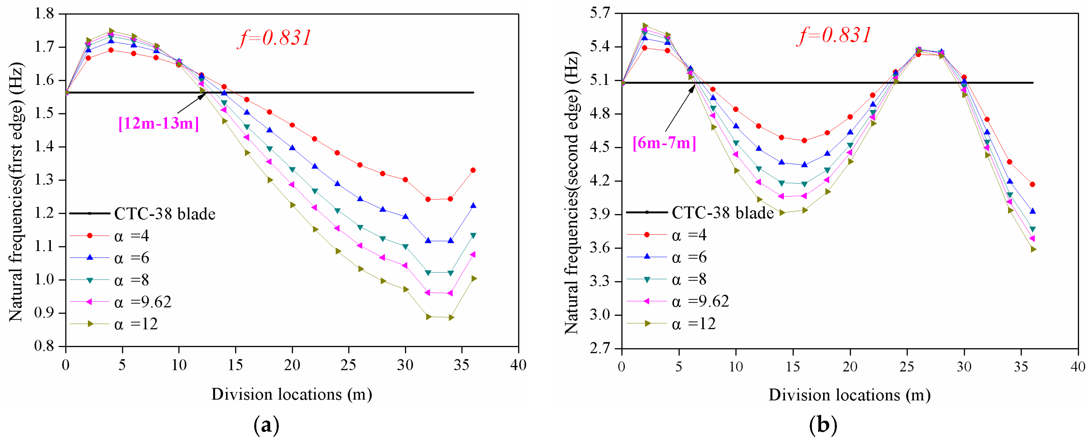
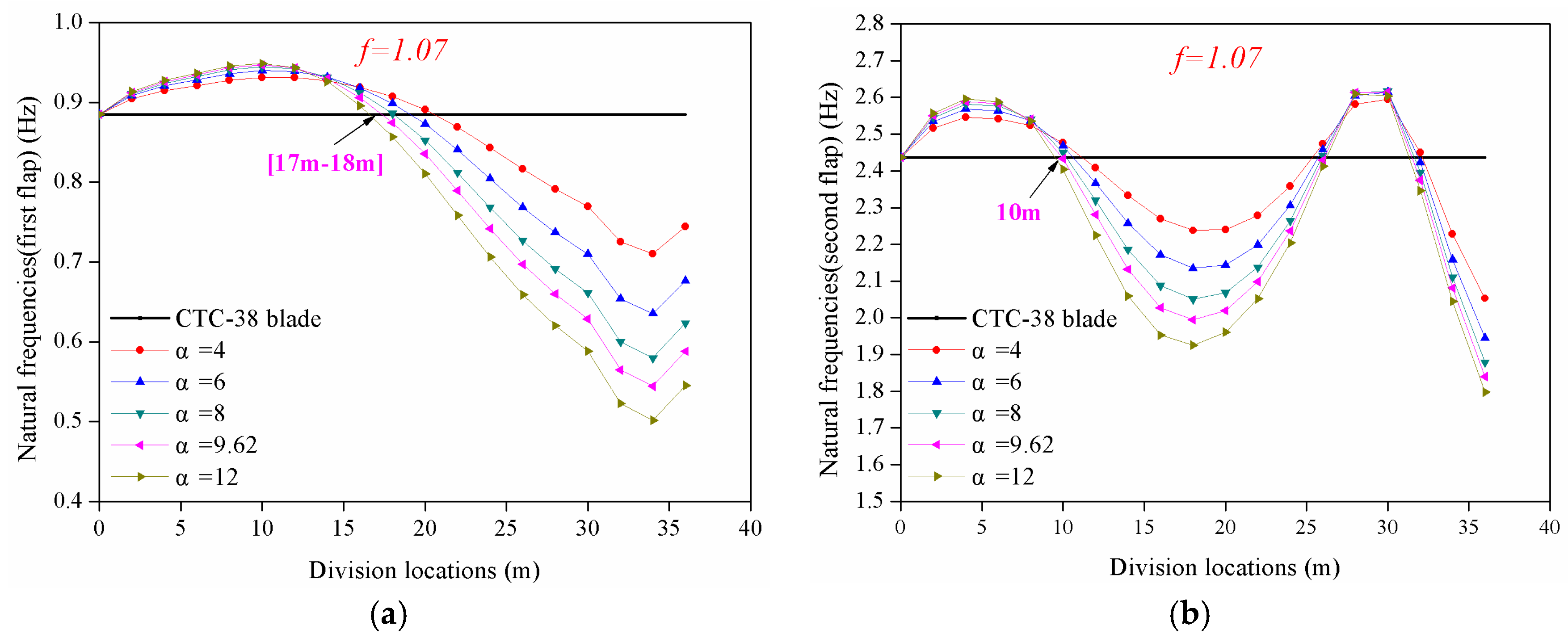
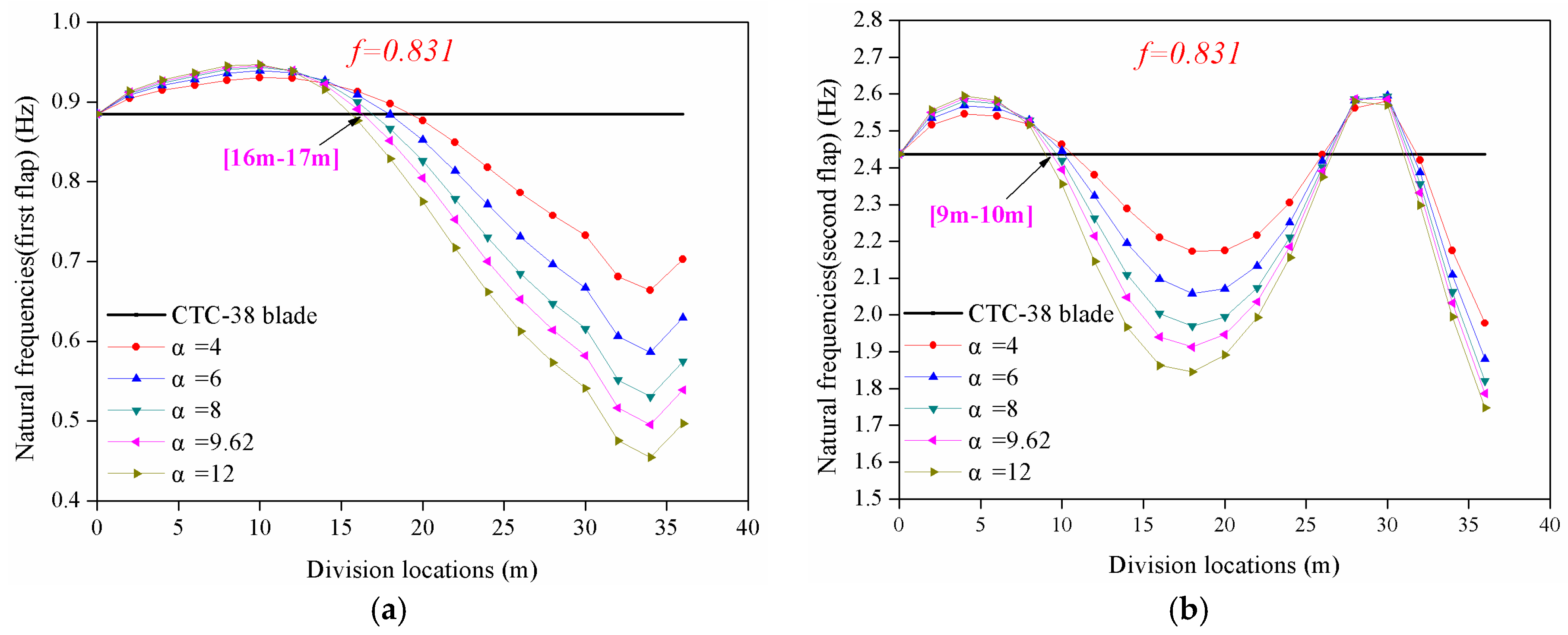
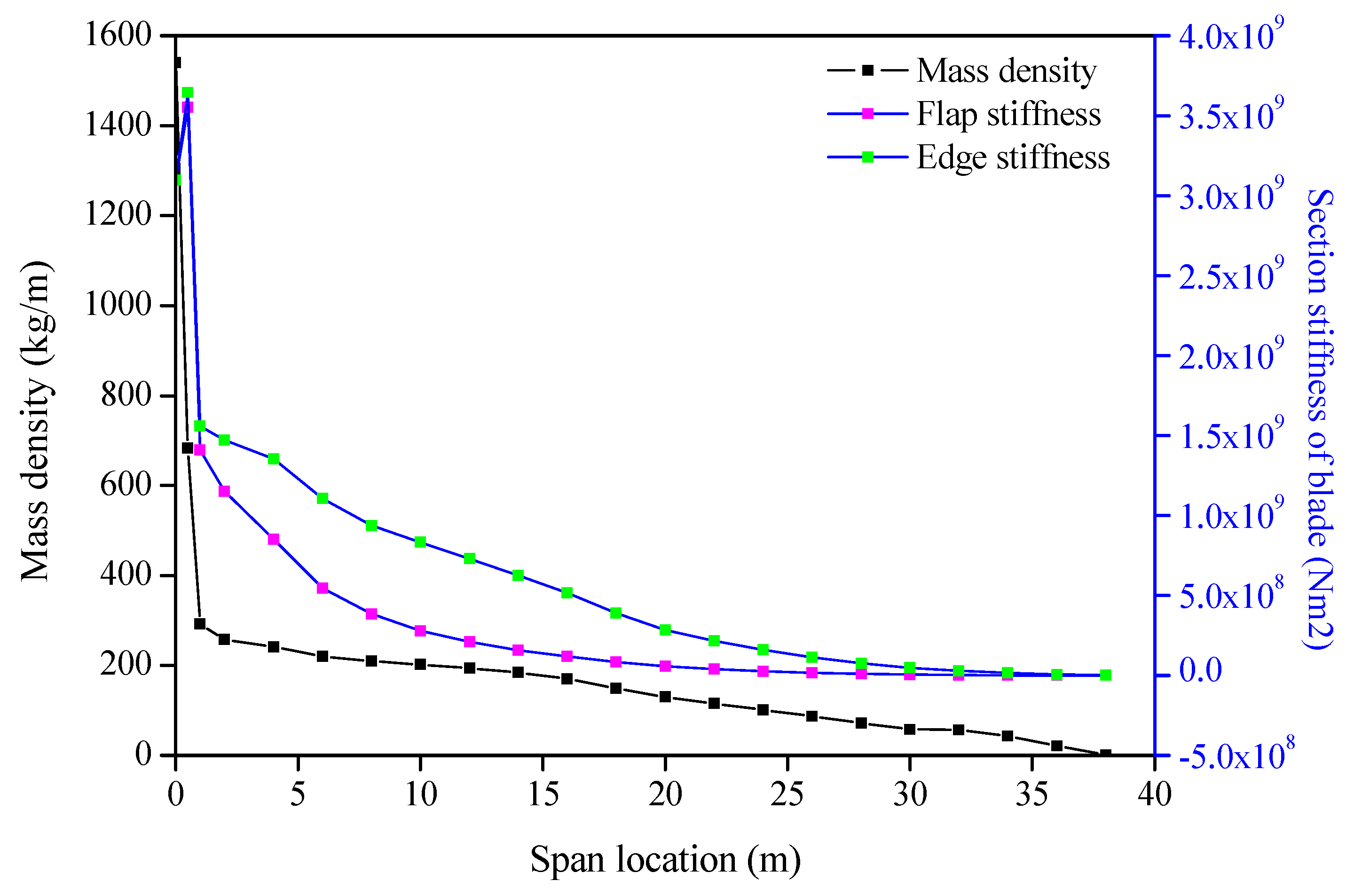
3.3. Natural Frequencies Variation of Sectional Blades

For 10.9 class bolts that are rolled before heat treatment, the detail category Δ σ k , C is 71 MPa, and 10 7 cycles are used to evaluate fatigue strength. Unidirectional FRC was the main material used for this analysis, and the material properties were obtained from Sandia’s report [43]. The fluctuating stress ( Δ σ k , A ) F R C , o and ( Δ σ k , A ) b , s are 74.46 MPa and 45.55 MPa for unidirectional glass FRC and bolts, respectively, such that ω is 1.63. The elastic modulus E F R C , o of unidirectional glass FRC equals 41.8 GPa, and the elastic modulus E b , s of the bolts is 205 GPa, such that μ equal 4.90, and γ is roughly 1.2. Substituting Equations (23) and (34) into Equation (12) gives:
α x ( y ) = γ × ( Δ σ k , A ) F R C , o ( Δ σ k , A ) b , s × E b , s E F R C , o = 9.62 .
For a typical embedded sleeve connection with M30 bolts, Θ F R C , s equals 0.877, and f ( Θ F R C , s ) equals 1.07 and 0.831 for unidirectional and tri-axial glass FRCs, respectively (Figure 9). Therefore, β equals 8.99 and 11.58 for unidirectional and tri-axial glass FRCs, respectively. For T-bolted joints, Θ F R C , s would be larger than that of the embedded sleeve connection.
According to the scheme proposed in Section 2.3, we assumed that the stiffness of the SB-38 sectional blade increases with α of 4, 6, 8, 9.62, and 12 as much as the original blade at the division location. At α = 9.62 is a specific characteristic for the CTC-38 blade, and the other values of 4, 6, 8, and 12 were also considered to study the impacts on natural frequencies. For FRCs, f ( Θ F R C , s ) values of 1.07 and 0.831 were both selected in the analysis. Since low order vibration frequencies are prone to be excited, and the first two order edge and flap natural frequencies are generally required to be checked by GL guidelines and certification bodies for long blades, the first two edge and flap natural frequencies were analyzed.
Figure 10 exhibits the first and second edge natural frequencies with different α at various division locations ( f = 1.07). From Figure 10a, it can be seen that the first natural edge frequency increases when the division location is less than 13 m or 14 m from the blade root. The increment of natural frequency keeps pace with α, but within 20% of the original value. Conversely, the first edge natural frequencies decrease faster and faster when division locations are from 14 m to the blade tip.
Figure 10b indicates that the second natural edge frequencies increase when the division location is within 6 m and between 24 and 30 m, and the increments of natural frequencies keep pace with α, but are within 9% and 7% of the original value. When the division location falls in the interval of 30 m to the blade tip, the second edge natural frequency of the sectional blade decreases quickly.
When f equals 0.831 (Figure 11), the trend of the first and second edge natural frequencies vary consistently with that of 1.07 stated above. The variation in natural frequency is more serious, which makes natural frequencies lower than that for f = 1.07.
Figure 12 shows the first and second flap natural frequencies with different α-values at various division locations ( f = 1.07). The trend in flap natural frequencies varies similarly with those in the edge-wise direction. From Figure 12a, the first natural flap frequencies increase when the division location is within 17 m, and the increment of natural frequency fluctuates with α, but within 6% of the original value. When the division location is far away from 17 m, the first flap natural frequencies of the sectional blade decrease increasingly faster to the blade tip. The maximum decrease could be about 39% of the original value.
Figure 12b shows that second natural flap frequencies increase when the division location is within 10 m, and between 24 and 30 m, and the increase in natural frequency fluctuates with α, but at most is within 7% of the original value. When the division location falls within the interval of 10–24 m, and 30 m to the blade tip, the second flap natural frequency of the sectional blade decreases quickly.
When f equals 0.831 (Figure 13), the trend of the first and second natural flap frequencies vary in line with that of 1.07 stated above.
In summary, in terms of variation in natural frequencies of the blade, the first flap and edge natural frequencies increase slightly when the division location would be from the blade root to around 35% of the blade (13 m), and the second flap and edge natural frequencies change slightly if the division is located from the blade root to around 20% of the blade (around 8 m), while the natural frequencies shift significantly beyond this region, considering flap and edge natural frequencies, the reduction in frequencies would probably result in structural resonance of the WTs.
Trade-offs should be made to simultaneously fulfill both manufacturing and structural performance requirements. The blade with higher natural frequencies would more easily avoid resonance in the WT according to the vibration Campbell diagram. Around 8 m (20%) from the blade root should be a suitable location for a sectional blade, where the transportation advantages are also evident with a balance in the weight, with a 2465 kg inner part (42% of total mass) and a 3356 kg outer part (58% of total mass). Moreover, the sectional blade bends slightly when it runs, and that pre-tension of the bolted joint does not tend to loosen.

4. Trends of Sectional Blades for Large WTs

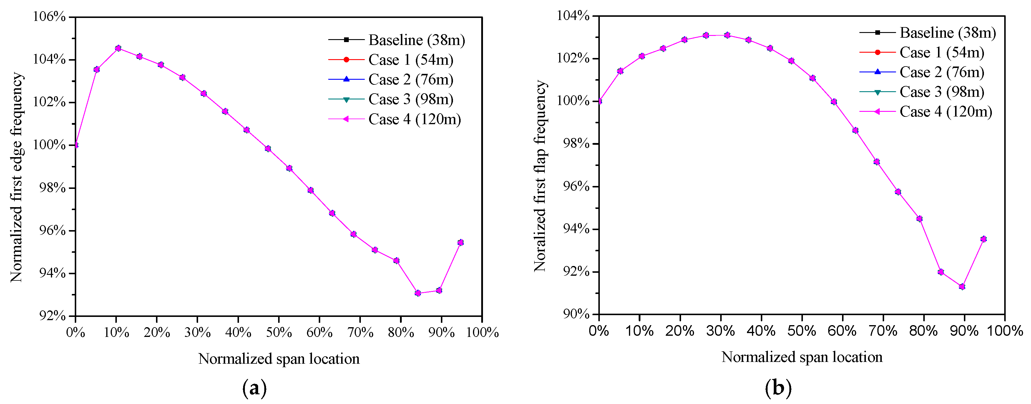
4.1. Upscaling Studies of Sectional Blades

Scaling WTs provides reasonable and fast access for evaluating loads and geometrical features for up-scaled blades in relation to the existing blade. The geometrical dimensions of different scaled blades are proportional to the scale factor, denoted as R . Correspondingly, the structural and aerodynamic parameters are related to the scale factor, as shown in Table 2. The aerodynamic bending moment can be orthogonally divided into flap-wise moment M x and edge-wise moment M y [44].
Physical dimension h ( x ,     y ) is a function of x and y coordinates at a given position, as well as axial stress due to centrifugal forces:
σ F c = F c A .
Direct stress due to aerodynamic moments at position (x, y) is expressed as
σ M = ( θ M x + ϑ M y ) h ( x , y ) I h ( z ) .
Direct stress due to moments of blade weight at position (x, y) is expressed as
σ m = m g l h ( x , y ) I h ( z ) .
Table 3 indicates that the direct stress induced by centrifugal forces and aerodynamic moments remain constant after scaling the blade. This is also validated by NREL research [45], where the stress from flap-wise moments stays identical after scaling. As for bolted joints, the wrench space for bolt pretension and connecting bolts are approximately proportional to the bolt diameter [31]. Therefore, by scaling the geometrical dimensions of the blade and the connecting bolts for sectional blades, the bolts can be allocated with the same ratio distributed along the blade shells. Since the load-carrying capacity of bonded joint with linear increase overlap length is lower than the corresponding proportional load in adhesively bonded joints, the embedded sleeve joint will not be able to supply enough strength for the upscale sectional blades. Moreover, the fatigue strength of the connecting bolts is reduced with a larger bolt diameter, with an additional reduction factor of α k ( = ( 30 mm d ) 0.25 ) according to the GL guidelines [27].
In addition, the axial stress of the bolts resulting from flap-wise bending moments stays the same, so the diameter of the connection bolts for sectional blades changes with scale factor R .
At the same time, bending moments induced by gravitation, compared to aerodynamic moments, vary at a higher ratio. The stress due to the bending moment of the blade weight is amplified linearly with the dimension of the blade, which further indicates that a limitation on blade length exists when extending blades, and the lightweight design of blades then becomes highly important and indispensable when examining the strength tolerance of the materials. The gravitational force mainly produces an edge-wise bending moment, so the extreme stress at the leading and trailing edges evidently increases when extending blades. Because of this, more attention should be paid to the edge-wise bending loads and to the stress of the bolts on the leading and trailing edges.
When the scale factors are 1, 1.414, 2, 2.582, and 3.162, the blade length and rotor power are listed in Table 4.
Figure 14 shows the variation of the first edge and flap natural frequencies of differently sized blades, where the span-wise location, on the x-axis, and the variation of natural frequencies, on the y-axis, are normalized for comparison. It is clear that the relative variation in natural frequencies is kept constant when the blade is divided at relative identical locations for the scaled blades.
According to the rule of geometrical similarity, the assembling performance ( d C d x , d T d x ) for sectional blades remains the same.

4.2. Challenges and Recommendations for Large Sectional Blades

When considering the connection strength of sectional blades, the diameters of the connection bolts increase with the scale factor, whereas the stress carried by the bolts due to bending moments of aerodynamic and centrifugal forces remain the same after amplifying the blade. However, the stress carried by bolts due to the bending moment of blade gravitation increases and additional bolt stress is produced, mainly at the leading and trailing edges. If possible, a lightweight design could be implemented so that the increase in stress due to blade gravitation is reduced. Nevertheless, large-diameter connection bolts would scatter the stress by bolts and thus reduce the reliability of the bolt connection of sectional blades [27]. This explains why larger sectional blades are susceptible to failure [13,15,24]. From the results in Section 3.1, the connection strength of sectional blades is more critical at the midpoint of the blade than at the blade root or blade tip. Two-row bolted joints provide an alternative for overcoming the insufficient strength of the blade connection. As for embedded sleeve bolted joints for sectional blades, the load capacity of bonding works by shear force transfer on the interface between sleeves and FRC. Due to uneven shear stress along the bonding interface, longer overlaps on the bonded joint cannot sustain the desired loads by upscaling the overlap length of bonding. The bonded strength can no longer meet the requirements for larger sectional blades. Innovative attempts could help to improve the strength of connections by using thicker airfoils around the division locations in the aerodynamic design.
With respect to the natural vibration of blades, resonance is promoted when the division is situated at the mid-point or the blade tip. However, resonance avoidance can be partly realized by the control regulation of WTs. Meanwhile, the effect of large deflection of the sectional blade at the division location on the structural reliability should be experimentally reviewed.
Since assembling the segment joint could not be improved in larger sectional blades, a novel aerodynamic design of sectional blades may be a more viable approach, potentially by using a uniform profile around the division location. However, the power loss of the WT should be evaluated to determine viability.
Finally, the cost increase after blade separation should be comprehensively addressed by considering materials, equipment, labor force, transportation routes, and vehicles. On account of mass density and stiffness deduction and their distribution assumed around the division location, cost increases after blade separation is reduced from the blade root to the blade tip.

5. Conclusions

The location of the division on sectional blades has significant influences on connection reliability, manufacturing accessibility, and structural dynamics. This paper proposed a method to evaluate the bolt strength, fabrication accessibility, and natural frequencies at different division locations based on the characterization of the axial bolts, practical requirements for bolt assembling, and stiffness and mass density variation after blade separation. Then, a case study on a 38-meter commercial blade, as a representative of structural and aerodynamic characteristics of the modern blade, was conducted to investigate the effects of the division location on the WT performance. Finally, upscaling studies were completed to address the challenges of large sectional blades according to the geometrical similarity rule. The conclusions drawn are as follows.
The beneficial interval of the division for sectional blades is located in the middle of the blades, when considering the manufacturing and assembling of the blade connection of current blades.
The optimal interval of the location for the division for sectional blades is situated at around 20% from the blade root, taking into consideration the connection strength and natural frequency variation of the sectional blade, as well as the convenience of manufacturing and assembly.
Key approaches to reduce additional increases in stiffness and weight are to improve fatigue strength and to choose low-modulus connection bolts.
Upscale-diameter connection bolts may be inadequate to meet the requirements for identical upscaled sectional blades due to the relatively low mechanical reliability of large diameter bolts. The lightweight design of blades is indispensable for extremely large sectional blades, especially to reduce bolt stress around the trailing and leading edges.
The effect of blade separation on the natural frequencies for scaled sectional blades is the same as that for the base sectional blade, and the assembling accessibility of the scaled sectional blade is consistent with that of the base blade.

Acknowledgments

The authors gratefully acknowledge that the work is financially supported by the National Science Foundation of China (No. 51476171, No. 51376180) and the Key Laboratory of Wind Energy Utilization (KLWEU-2016-0301). The authors also thank Xiao Chen for comments and suggestions on this paper. We are also grateful to anonymous reviewers for their suggestions to improve this paper.

Author Contributions

Analysis of the key issues, theoretical deduction, and Matlab programs were carried out by Zhiwen Qin, who also wrote the manuscript. Lei Zhang helped to revise the manuscript, while Ke Yang, Jihui Wang, Caicai Liao, and Jianzhong Xu critically revised the paper and provided constructive criticism.

Conflicts of Interest

The authors declare no conflict of interest.

Nomenclature

SymbolDesignation
A Cross-section area of blade section, general
A b Cross-section area of bolt, general
A bolt Unit cross-section area of assumed bolt
A b , s Cross-section area (bolts) of the sectional blade at the division location
A F R C , o Cross-section area (FRC) of the original blade
A i Cross-section area unit, general
A m Contact area of clamped members of a bolted joint
A s Cross-section area of the sectional blade at the division location
A shell Unit cross-section area of assumed blade shell
a Constant related to position at the cross-section plane
b Constant related to position at the cross-section plane
C 
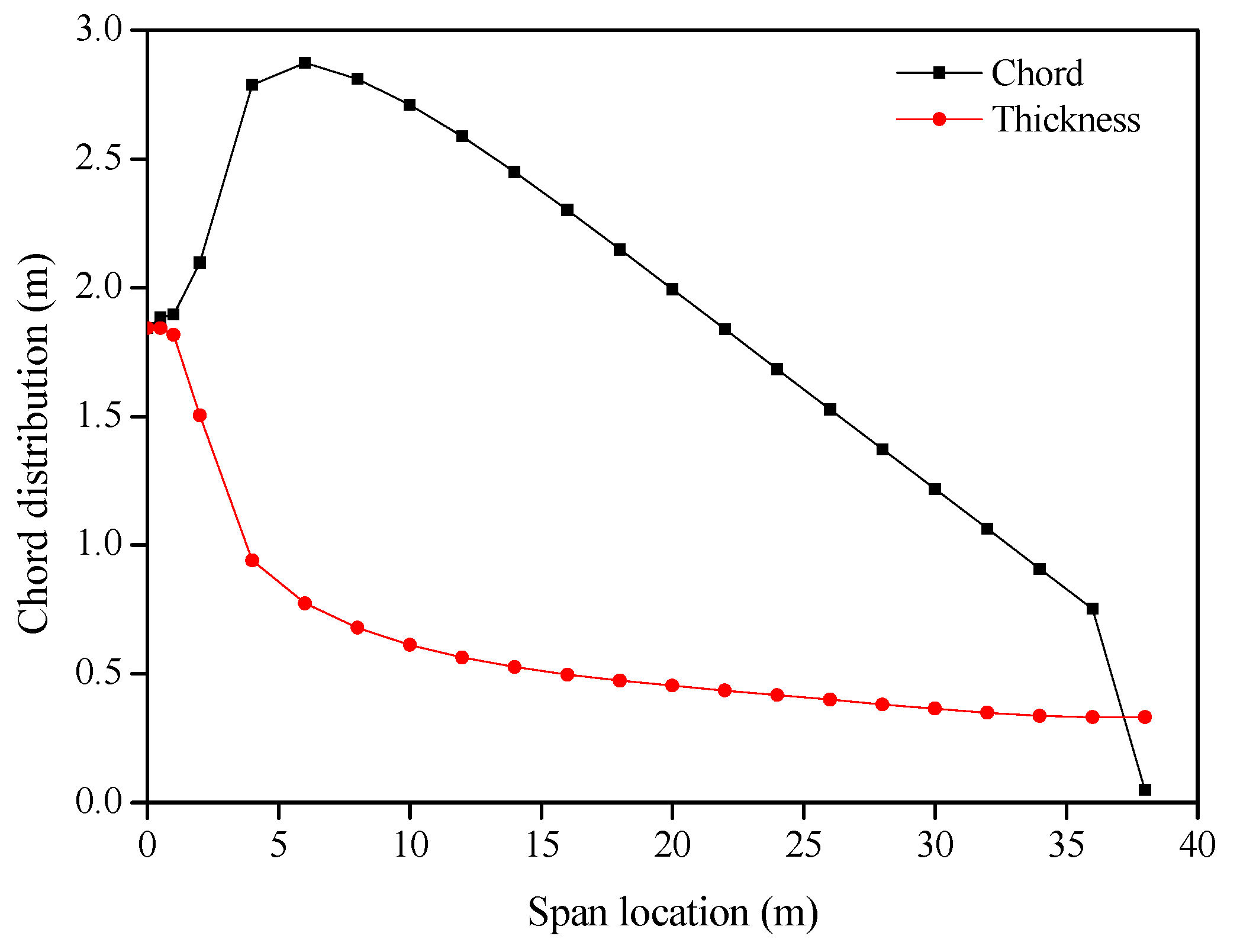
The chord of the blade section
c Constant related to position at the cross-section plane
D k 
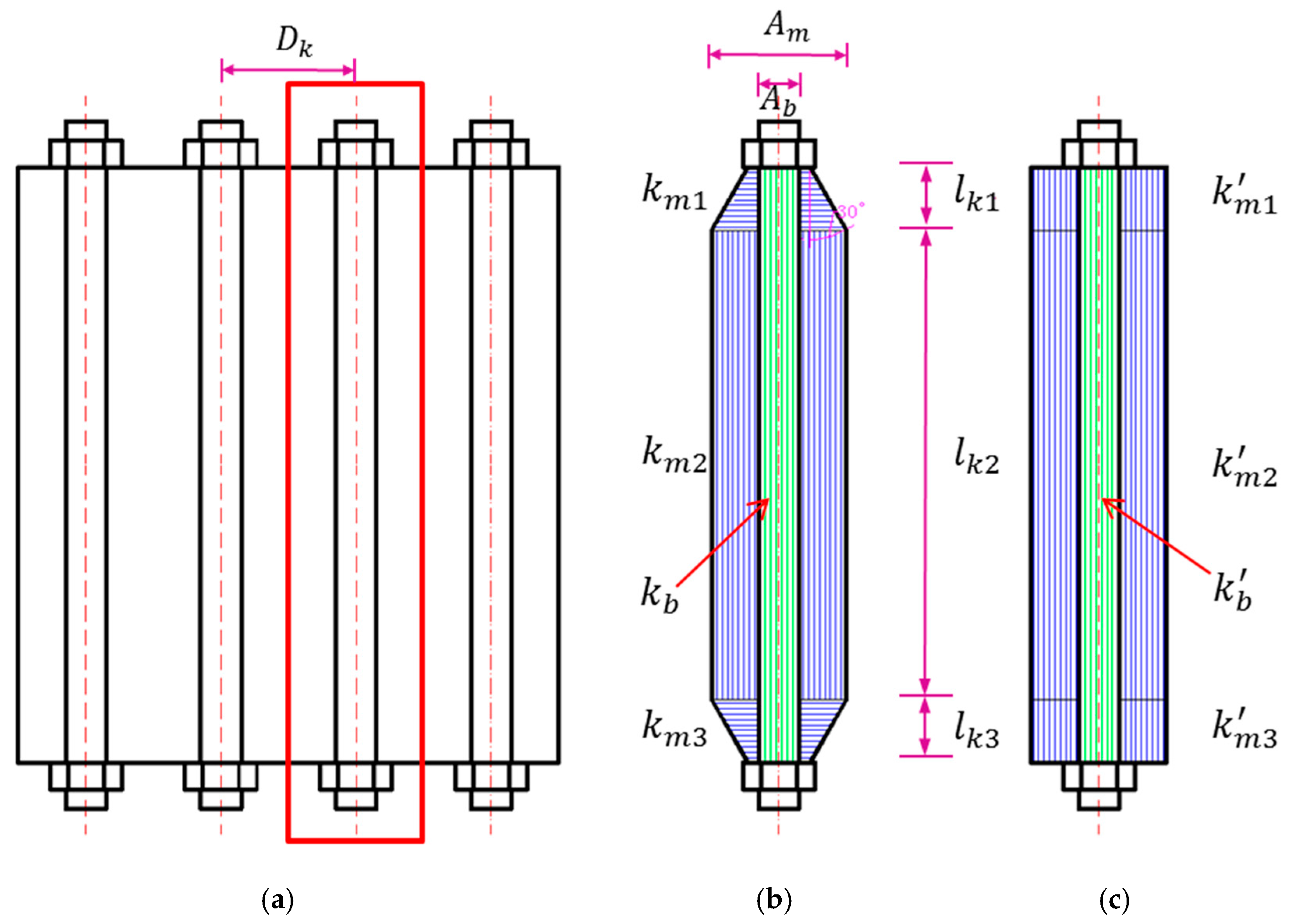
Distance of adjacent bolts in multi-bolted joints of the sectional blade
E Young’s modulus, general
E b Young’s modulus of the bolt material
E F R C , o Young’s modulus of FRC material
E m Young’s modulus of the clamped member material
E e , s Equivalent young’s modulus of materials of the sectional blade at the division location
E s e Equivalent young’s modulus of materials of the bolted joint based on the ideal stress model
F c Centrifugal force of blades
f 
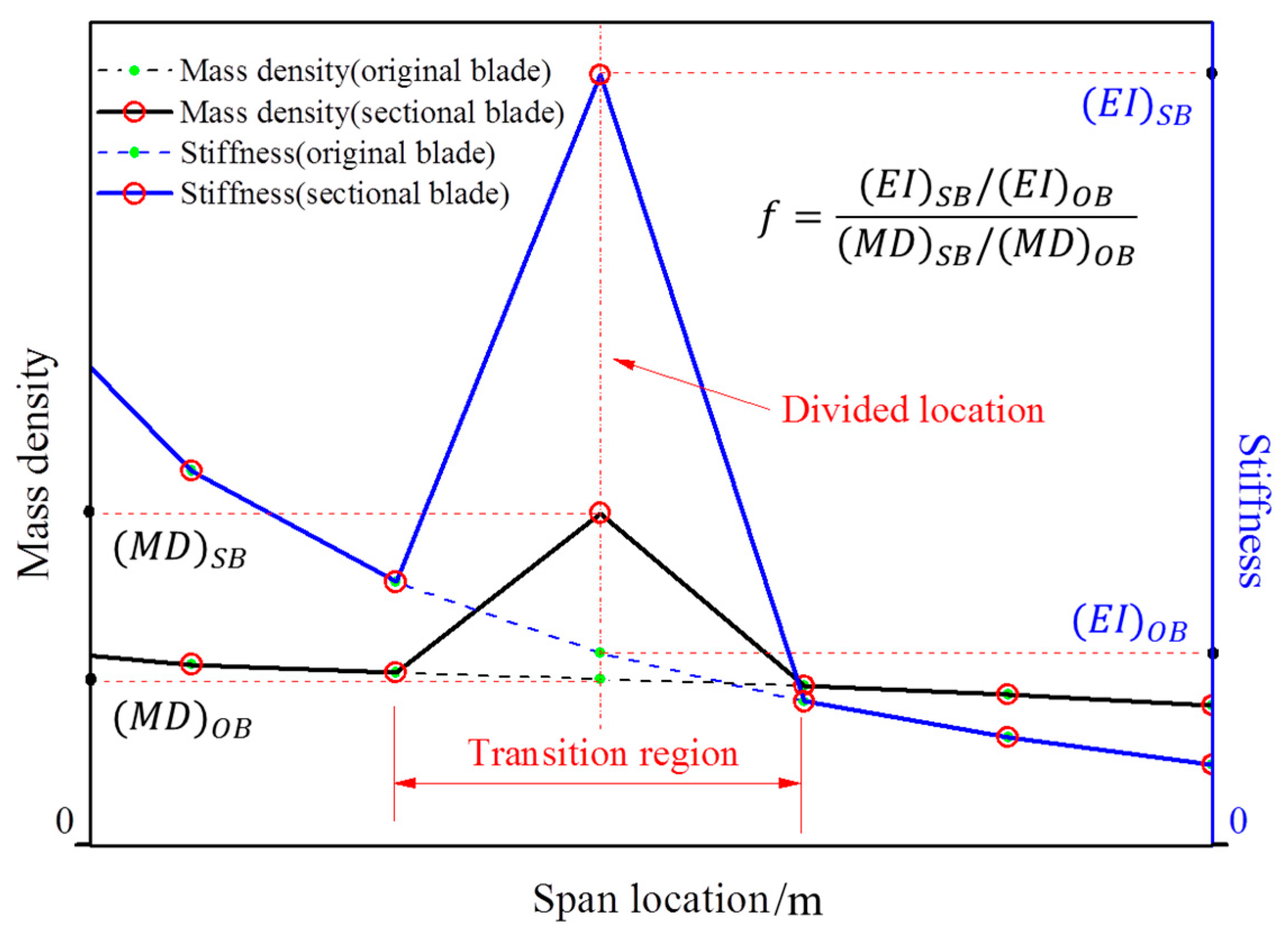
Ratio of section bending stiffness to mass density of the sectional to the original blade
h ( x , y ) A physical dimension, decided by coordinates at given position
k b Axial stiffness of the bolt
k m Axial stiffness of the clamped members
k m Axial stiffness of clamped members based on the ideal stress model, shown in Figure 5c
k m 1 Axial stiffness of the upper clamped member based on hypothesis stress model, shown in Figure 5b
k m 1 Axial stiffness of the upper clamped members based on the ideal stress model, shown in Figure 5c
k m 2 Axial stiffness of the middle clamped member based on hypothesis stress model, shown in Figure 5b
k m 2 Axial stiffness of the middle clamped member based on the ideal stress model, shown in Figure 5c
k m 3 Axial stiffness of the bottom clamped member based on hypothesis stress model, shown in Figure 5b
k m 3 Axial stiffness of the bottom clamped member based on the ideal stress model, shown in Figure 5c
l Span–wise length from the rotor center to the center of blade gravity
l k Axial length of clamped members, shown in Figure 5
l k 1 Axial length of upper clamped members, shown in Figure 5
l k 2 Axial length of middle clamped members, shown in Figure 5
l k 3 Axial length of bottom clamped members, shown in Figure 5
M x Bending moments on the x-axis at the cross section
M y Bending moments on the y-axis at the cross section
n Load introduction factor
N Permissible load cycle number, defined by Eurocode 3
I h ( z ) Area moment of inertia on the user-defined h -axis
I x x Area moment of inertia on the x-axis
I x y Product moment of area
I y y Area moment of inertia on the y-axis
R Scale factor for different geometrical blades
S x * First moment of area on the x-axis
S y * First moment of area on the y-axis
T Thickness of the blade section
x Coordinate value on the x-axis
x i x coordinate of centroid of the cross-section unit
y Coordinate value on the y-axis
y i y coordinate of centroid of the cross-section unit
X Horizontal coordinate axis
Y Vertical coordinate axis
Δ F b Bolt load variation of the bolted joint
Δ F e External load variation of the bolted joint
Δ F f b Fatigue bolt load variation of the bolted joint
Δ F f e External fatigue load variation of the bolted joint
( Δ σ k , A ) b , s Fluctuating stress limit of bolts for a given fatigue cycles in the sectional blade
( Δ σ k , A ) F R C , o Fluctuating stress limit of FRC for a given fatigue cycles in the original blade
Δ σ k , A Fluctuating stress limit for a given fatigue cycles
Δ σ k , C Detail category with respect to 2 × 10 6 fatigue cycles, defined in Eurocode 3
Δ σ z Fluctuating direct stress along the z-axis due to bending moments
( E I ) O B Bending stiffness of the original blade
( E I ) S B Bending stiffness of the sectional blade
( E I x x ) O B Bending stiffness of the original blade on the x-axis
( E I x x ) S B Bending stiffness of the sectional blade on the x-axis
( E I y y ) O B Bending stiffness of the original blade on the y-axis
( E I y y ) S B Bending stiffness of the sectional blade on the y-axis
( E A ) O B Axial stiffness of the original blade
( E A ) S B Axial stiffness of the sectional blade
( M D ) O B Mass density of the original blade, equal to beam mass of unit length
( M D ) S B Mass density of the sectional blade, equal to beam mass of unit length
Load factor of the bolted joint
Load factor of the bolted joint, obtained by the ideal stress model
φ Axial stiffness ratio of to bolt, calculated by the ideal stress model
θ Constant related to position at the cross-section plane
ϑ Constant related to position at the cross-section plane
φ m i n Minimum value of φ
Θ F R C , s Cross-section area portion of FRC at the division location
ρ Density
ρ b , s Density of connection bolt material for sectional blades
ρ i Density of components
ρ e , s Equivalent density of the sectional blade at the division location
ρ F R C , o Density of FRC material of the original blade
σ F c Axial stress due to centrifugal force of blades
σ m Direct stress due to blade weight, m g
σ M Direct stress due to bending moments, M x and M y
σ z Direct stress along the z-axis due to bending moments
α x Bending stiffness (on the x-axis) ratio of the original blade to the sectional blade at the division location
α y Bending stiffness (on the y-axis) ratio of the original blade to the sectional blade at the division location
β Cross-section mass density ratio of the original blade to the sectional blade at the division location
μ Variable expressing A b , s A F R C , o
ω Vaing E b , s E F R C , o
φ Variable expressing s A s E e , s A b , s E b , s
γ Magnification factors for φ

Abbreviations

WTWind turbine
FRCFiber-reinforced composite
GFRCGlass-fiber-reinforced composite

Appendix A

Figure A1. Chord and thickness distribution of the CTC-38 blade.
Energies 10 01404 g015
Figure A2. Mass density and flap and edge stiffness of the CTC-38 blade.
Energies 10 01404 g016
Figure A3. Equivalent fatigue loads of the CTC-38 blade (m = 3 and m = 5) with no consideration of mean value.
Energies 10 01404 g017

References

  1. Hernández, C.V.; Telsnig, T.; Pradas, A.V. JRC Wind Energy Status Report 2016 Edition. Available online: www.apren.pt/fotos/newsletter/conteudos/wind_energy_status_report-2016_joint_research_centre_2017_1490879640.pdf (accessed on 7 September 2017).
  2. Barr, A. Blade technology trends and market developments. In Proceedings of the Sandia 2014 Wind Turbine Blade Workshop, Albuquerque, NM, USA, 25–29 August 2014. [Google Scholar]
  3. IWES Develops Test Field for Offshore Wind Turbines. Available online: http://der-lab.net/iwes-develops-test-field-for-offshore-wind-turbines/ (accessed on 7 September 2017).
  4. Smith, K. WindPACT Turbine Design Scaling Studies Technical Area 2: Turbine, Rotor, and Blade Logistics. Available online: https://www.nrel.gov/docs/fy01osti/29439.pdf (accessed on 7 September 2017).
  5. Cotrell, J.; Stehly, T.; Johnson, J.; Roberts, J.; Parker, Z.; Scott, G.; Heimiller, D. Analysis of Transportation and Logistics Challenges Affecting the Deployment of Larger Wind Turbines: Summary of Results. Available online: www.nrel.gov/docs/fy14osti/61063.pdf (accessed on 7 September 2017).
  6. Griffin, D.A. Blade System Design Studies Volume I: Composite Technologies for Large Wind Turbine Blades. Available online: https://pdfs.semanticscholar.org/7c26/295163ed8dd054f2a6c15127c54ab9003a25.pdf (accessed on 7 September 2017).
  7. European Wind Energy Association. UpWind: Design Limits and Solutions for Very Large Wind Turbines; European Wind Energy Association: Brussels, Belgium, 2011. [Google Scholar]
  8. Sieros, G.; Chaviaropoulos, P.; Sørensen, J.D.; Bulder, B.; Jamieson, P. Upscaling wind turbines: Theoretical and practical aspects and their impact on the cost of energy. Wind Energy 2012, 15, 3–17. [Google Scholar] [CrossRef]
  9. Ashuri, T.; Zaaijer, M.B.; Martins, J.R.; Zhang, J. Multidisciplinary design optimization of large wind turbines—Technical, economic, and design challenges. Energy Conver. Manag. 2016, 123, 56–70. [Google Scholar] [CrossRef]
  10. Saenz, E.; Nuin, I.; Montejo, R.; Sanz, J. Development and validation of a new joint system for sectional blades. Wind Energy 2014, 18, 419–428. [Google Scholar] [CrossRef]
  11. MEGAWIND. 30 m Split Rotor Blade. Available online: http://www.cres.gr/megawind/split_rotor_blade.htm (accessed on 7 September 2017).
  12. Dutton, A.G.; Geiger, T.; Hahn, F.; Olesen, M.; Kenche, C.; Korsgaard, J.; Van Delft, D.R.V. Design concept for sectional wind turbine blades. In Proceedings of the European Wind Energy Conference (EWEC99), Nice, France, 1–5 March 1999. [Google Scholar]
  13. Dutton, A.G.; Kildegaard, C.; Dobbe, T.; Bensoussan, R.; Kensche, C.; Hahn, F.; Van Delft, D.R.V.; De Winkel, G.D. Design, Structural Testing, and Cost Effectiveness of Sectional Wind Turbine Blades. Available online: http://cordis.europa.eu/project/rcn/37637_en.html (accessed on 7 September 2017).
  14. Hahn, F.; Kensche, C.W.; Paynter, R.J.H.; Dutton, A.G.; Kildegaard, C.; Korsgaard, J. Design, fatigue test, and NDE of a sectional wind turbine rotor blade. J. Thermoplast. Compos. Mater. 2002, 15, 267–277. [Google Scholar] [CrossRef]
  15. Vionis, P.; Lekou, D.; Gonzalez, F.; Mieres, J.; Kossivas, T.; Soria, E.; Gutierrez, E.; Galiotis, C.; Philippidis, T.P.; Voutsinas, S.; et al. Development of a MW Scale wind turbine for high wind complex terrain sites: The MEGAWIND project. In Proceedings of the European Wind Energy Conference, Athens, Greece, 27 Feburary–3 March 2006. [Google Scholar]
  16. GAMESA, G-128 4.5 MW. Available online: http://www.gamesacorp.com (accessed on 7 September 2017).
  17. ENERCON, E-126 State of the Art. Available online: http://www.enercon.de/en-en/66.htm/ (accessed on 7 September 2017).
  18. ENERCON, ENERCON Delivers First E-115 Turbines for Export Project. Available online: http://northern-observer.com/enercon-delivers-first-new-turbines-export (accessed on 7 September 2017).
  19. Qin, Z. The First Sectional Wind Turbine Blade Has Successfully Passed Extreme Static Test in China. Available online: http://www.iet.cn/xwdt/kydt/201511/t20151120_4470609.html (accessed on 7 September 2017). (In Chinese).
  20. Nanami, N. Structural and Damage Assessment of Multi-Section Modular Hybrid Composite Wind Turbine Blade. Available online: http://oaktrust.library.tamu.edu/bitstream/handle/1969.1/153418/NANAMI-DISSERTATION-2014.pdf?sequence=1&isAllowed=y (accessed on 7 September 2017).
  21. Bhat, C.; Noronha, D.J.; Saldana, F.A. Structural Performance Evaluation of Segmented Wind Turbine Blade through Finite Element Simulation. Int. J. Mech. Aerosp. Ind. Mechatron. Manuf. Eng. 2015, 9, 980–989. [Google Scholar]
  22. Saldanha, F.A.; Rao, V.V.; Christopher, J.; Adhikari, R. Investigations on concepts for modularizing a horizontal axis wind turbine blade. In Proceedings of the ASME 2013 International Design Engineering Technical Conferences and Computers and Information in Engineering Conference, Portland, OR, USA, 4–7 August 2013. [Google Scholar]
  23. Xu, B.; Han, J.L. Numerical simulation on a joint segment of a prestressed prefabricated sectional wind turbine blade model. Eng. Mech. 2016, 33, 209–215. [Google Scholar]
  24. Kensche, C.W. Fatigue of composites for wind turbines. Int. J. Fatigue 2006, 28, 1363–1374. [Google Scholar] [CrossRef]
  25. LM. Meet a Record-Breaker: LM 88.4 P. Available online: http://www.lmwindpower.com (accessed on 7 September 2017).
  26. Burton, T.; Jenkins, N.; Sharpe, D.; Bossanyi, E. Wind Energy Handbook, 2nd ed.; John Wiley & Sons: Chichester, UK, 2011. [Google Scholar]
  27. Lloyd, G. Rules and Guidelines IV Industrial Services: Part I: Guideline for the Certification of Wind Turbines. Available online: https://www.scribd.com/doc/42161563/Guideline-for-the-Certification-of-Win-Turbines-Edition-2010-1 (accessed on 7 September 2017).
  28. Pilkey, W.D. Formulas for Stress, Strain, and Structural Matrices; John Wiley & Sons: Hoboken, NJ, USA, 2004. [Google Scholar]
  29. Bickford, J.H. Introduction to the Design and Behavior of Bolted Joints: Non-Gasketed Joints; CRC Press: Boca Raton, FL, USA, 2007. [Google Scholar]
  30. International Electrotechnical Commission. Wind Turbines—Part 3: Design Requirements for Offshore Wind Turbines; International Electrotechnical Commission: Geneva, Switzerland, 2009. [Google Scholar]
  31. Bickford, J.H. Handbook of Bolts and Bolted Joints; CRC Press: Boca Raton, FL, USA, 1998. [Google Scholar]
  32. Verein Deutscher Ingenieure. Systematic Calculation of High Duty Bolt Joints-Joints with One Cylindrical Bolt; Verein Deutscher Ingenieure: Düsseldorf, Germany, 2003. [Google Scholar]
  33. Lehnhoff, T.F.; Wistehuff, W.E. Nonlinear Effects on the Stresses and Deformations of Bolted Joints. J. Press. Vessel Technol. 1996, 118, 54–58. [Google Scholar] [CrossRef]
  34. Nassar, S.A.; Yang, X.; Gandham, S.V.T.; Wu, Z. Nonlinear Deformation Behavior of Clamped Bolted Joints under a Separating Service Load. J. Press. Vessel Technol. 2011, 133, 140–144. [Google Scholar] [CrossRef]
  35. Burguete, R.L.; Patterson, E.A. Effect of mean stress on the fatigue limit of high tensile bolts. ARCHIVE Proc. Inst. Mech. Eng. Part C J. Mech. Eng. Sci. 1995, 209, 257–262. [Google Scholar] [CrossRef]
  36. Megson, T.H.G. Structural and Stress Analysis; Butterworth-Heinemann: Oxford, UK, 2005. [Google Scholar]
  37. Hosseini-Toudeshky, H.; Jahanmardi, M.; Goodarzi, M.S. Progressive debonding analysis of composite blade root joint of wind turbines under fatigue loading. Compos. Struct. 2014, 120, 417–427. [Google Scholar] [CrossRef]
  38. Martínez, V.; Güemes, A.; Trias, D.; Blanco, N. Numerical and experimental analysis of stresses and failure in T-bolt joints. Compos. Struct. 2011, 93, 2636–2645. [Google Scholar] [CrossRef]
  39. Da Silva, L.F.M.; Öchsner, A. Modeling of Adhesively Bonded Joints; Springer: Berlin, Germany, 2008. [Google Scholar]
  40. Hobbs, J.; Burguete, R.; Heyes, P.; Patterson, E. The effect of eccentric loading on the fatigue performance of high-tensile bolts. Int. J. Fatigue 2000, 22, 531–538. [Google Scholar] [CrossRef]
  41. Eurocode 3: Design of Steel Structures-Part 1–9: Fatigue. Available online: http://www.phd.eng.br/wp-content/uploads/2015/12/en.1993.1.9.2005-1.pdf (accessed on 7 September 2017).
  42. Budynas, R.G.; Nisbett, J.K. Shigley’s Mechanical Engineering Design, 9th ed.; McGraw-Hill Series; Mechanical Engineering: New York, NY, USA, 2011. [Google Scholar]
  43. Griffith, D.T. The SNL100–01 Blade: Carbon Design Studies for the Sandia 100-Meter Blade; SAND2013–1178; Sandia National Laboratories: Albuquerque, NJ, USA, 2013. [Google Scholar]
  44. Hansen, M.O.L. Aerodynamics of Wind Turbines, 2nd ed.; Routledge: Abingdon, UK, 2008. [Google Scholar]
  45. Griffith, D.T.; Ashwill, T.D.; Resor, B.R. Large Offshore Rotor Development Design and Analysis of the Sandia 100-meter Wind Turbine Blade. In Proceedings of the 53 AIAA/ASME/ASCE/AHS/ASC Structures, Strutural Dynamics and Materials Conference, Honolulu, HI, USA, 23–26 April 2012. [Google Scholar]
Figure 1. Schematics of the section of a typical modern WT blade.
Energies 10 01404 g001
Figure 2. Stress calculation of a blade profile shell with a constant thickness.
Energies 10 01404 g002
Figure 3. Schematic diagram of the assembling position.
Energies 10 01404 g003
Figure 4. Cross-section mass density and stiffness distribution around the division location.
Energies 10 01404 g004
Figure 5. Stiffness equivalence of a bolted joint: (a) bolted joint group; (b) hypothesis stress model; (c) ideal stress model.
Energies 10 01404 g005
Figure 6. Maximum axial stress range of blade sections under fatigue loads.
Energies 10 01404 g006
Figure 7. Chords and their slopes along the blade.
Energies 10 01404 g007
Figure 8. Thicknesses and their slopes along the blade.
Energies 10 01404 g008
Figure 9. Ratio f ( Θ F R C , s ) changes with Θ F R C , s of a bolted joint.
Energies 10 01404 g009
Figure 10. Edge natural frequencies of sectional blades at different division locations ( f = 1.07): (a) first edge frequencies; (b) second edge frequencies.
Energies 10 01404 g010
Figure 11. Edge natural frequencies of sectional blades at different division locations ( f = 0.831): (a) first edge frequencies; (b) second edge frequencies.
Energies 10 01404 g011
Figure 12. Flap natural frequencies of sectional blades at different division locations ( f = 1.07): (a) first flap frequencies; (b) second flap frequencies.
Energies 10 01404 g012
Figure 13. Flap natural frequencies of sectional blades at different division locations ( f = 0.831): (a) first flap frequencies; (b) second flap frequencies.
Energies 10 01404 g013
Figure 14. Frequency variation for scaled sectional blades: (a) normalized first edge frequency and (b) normalized first flap frequency.
Energies 10 01404 g014
Table 1. Summary of studies on sectional blades.
Sponsor/SupporterTotal LengthDivision LocationConnection TypeStatusDate
DLR11.58 m5.79 m (50%)T-boltsHas run safely for 18 years1982
CLRC & LM & DLR & Delft13.4 m4.5 m (34%)Tube Static and fatigue test successfully2000
23.3 m7.3 m (31%)T-boltsStatic and fatigue test successfully2000
CRES29.65 m12.4 m (42%)T-boltsBolt failure in fatigue test2006
Enercon59 m24 m (40%)BoltsA small amount of installation2007
Gamesa62.5 m32 m (51%)Fitting channel and boltsLimited installation2010
Enercon56 m12 m (21%)BoltsPrototype installation2014
IET-wind, CAS38 m18 m (47%)Embedded sleeves and boltsStatic test already, preparing for fatigue test2015
Table 2. Impacts of scaling a rotor with scale factor R .
VariableRatio (Scaled/Base)
Power ( P ) R 2
Mass (m) R 3
Aerodynamic moments ( M x , M y ) R 3
Centrifugal forces ( F c ) R 2
Table 3. Stress impacts of scaling a rotor with scale factor R .
Stress CauseRatio (Scaled/Base)Features
Centrifugal forces ( σ F c ) R 0 Axial stress
Aerodynamic moments ( σ M ) R 0 Direct stress of bending
Mass ( σ m ) R 1 Direct stress of bending
Table 4. Information on scaled blades.
VariableBaselineCase 1Case 2Case 3Case 4
Scale factor1 2 = 1.4142 20 3 = 2.582 10 = 3.162
Blade length (m)38547698120
Rotor power (MW)1.5361015

