Design Improvisation for Reduced Harmonic Distortion in a Flux Pump-Integrated HTS Generator


 ,
,
Abstract
:1. Introduction
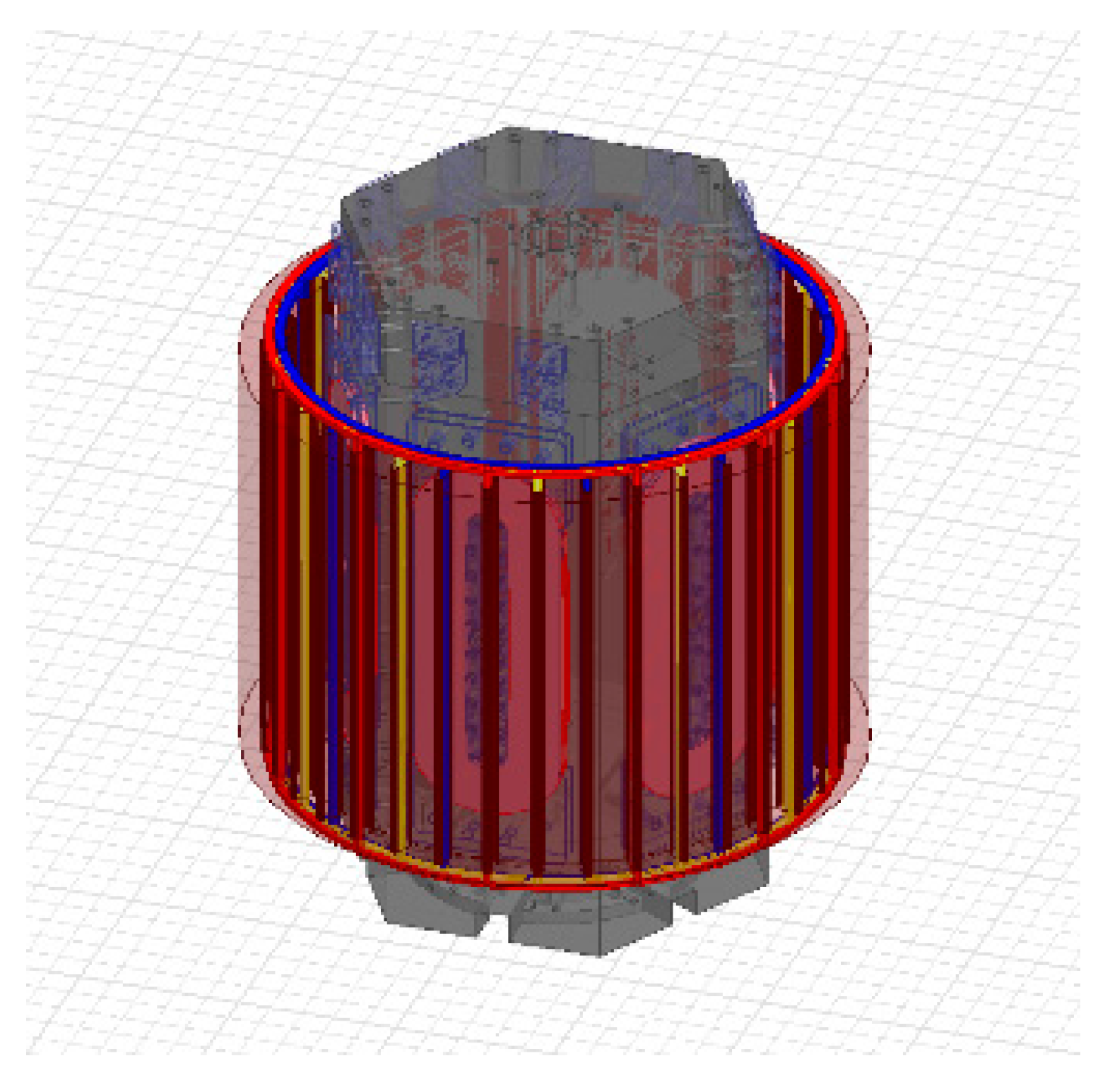
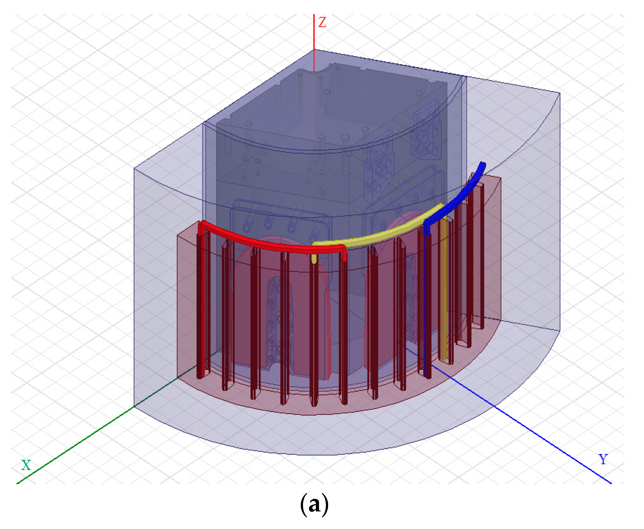
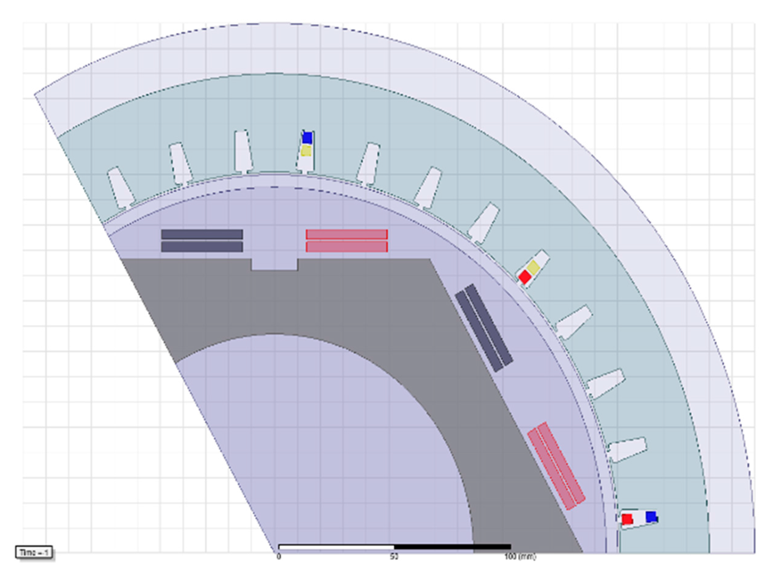
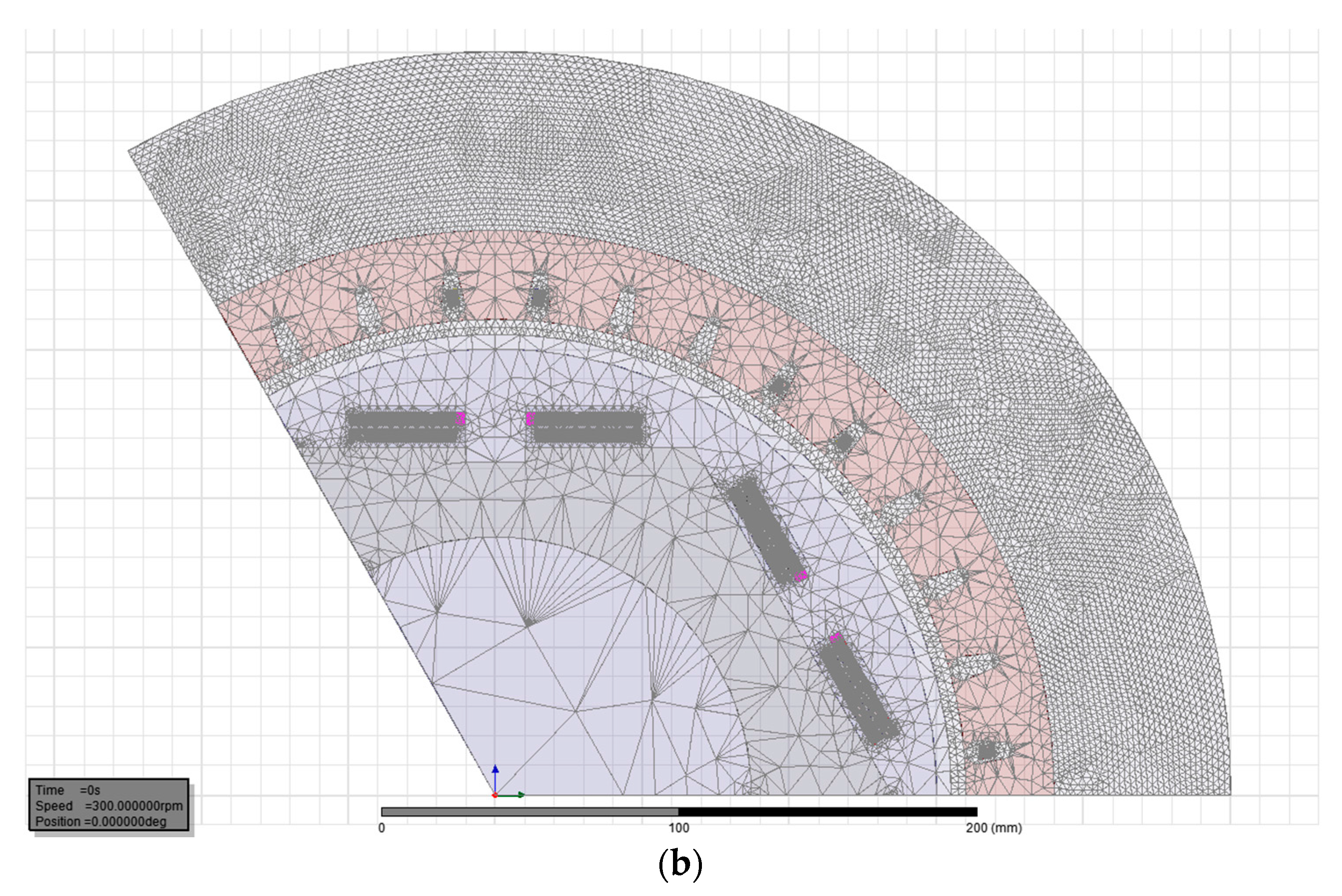
2. FEA Modelling of HTS Generator
3. Performance Analysis
3.1. Effect of Stator Yoke Material
3.2 Effect of Winding Pitch Factor (Kp)
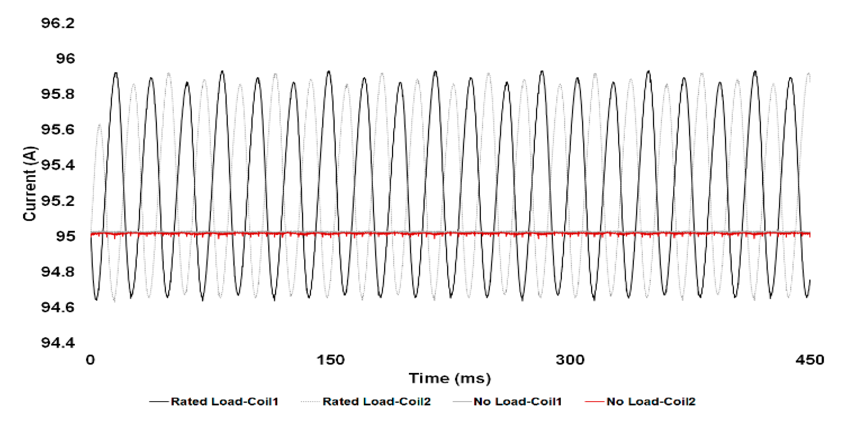
3.3. Effect of Load Configuration
- Star-Star (S-S)
- Star-Delta (S-D)
4. Results and Discussion
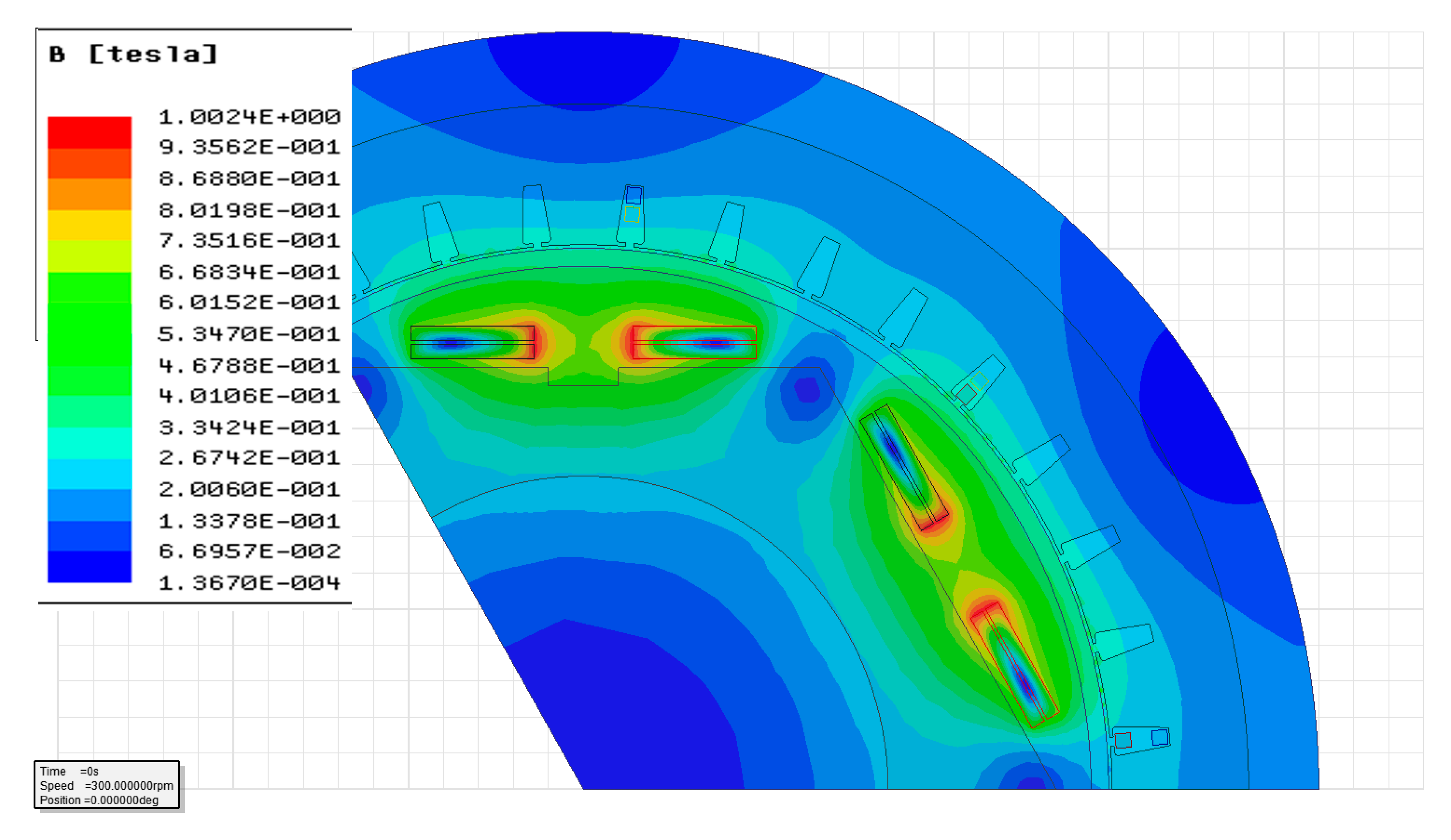
4.1 Field Pattern
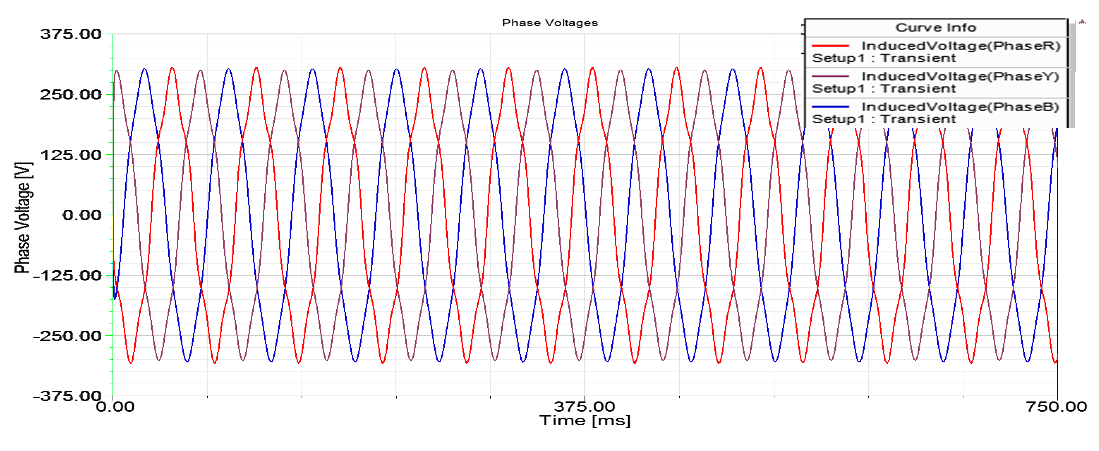
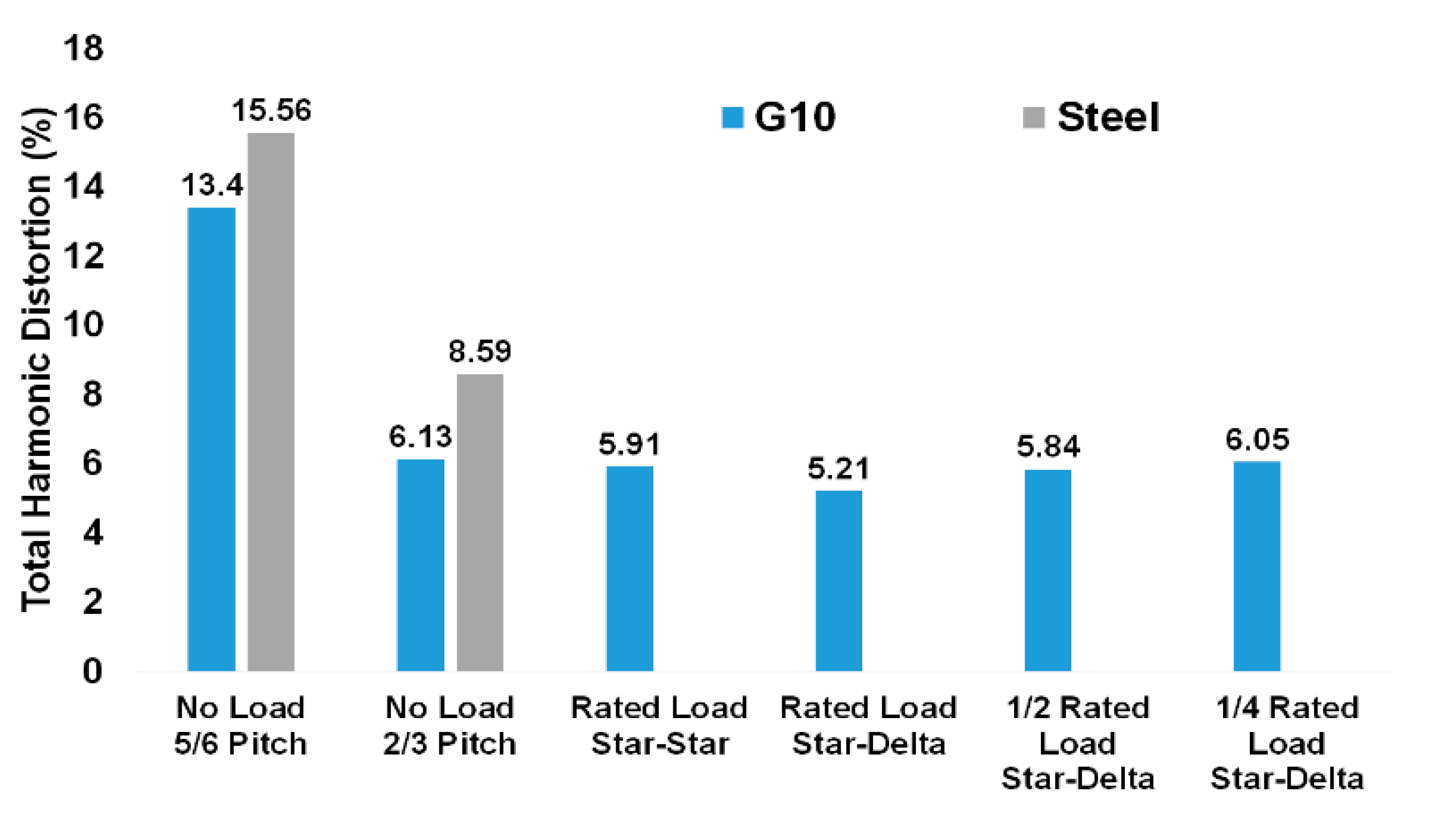
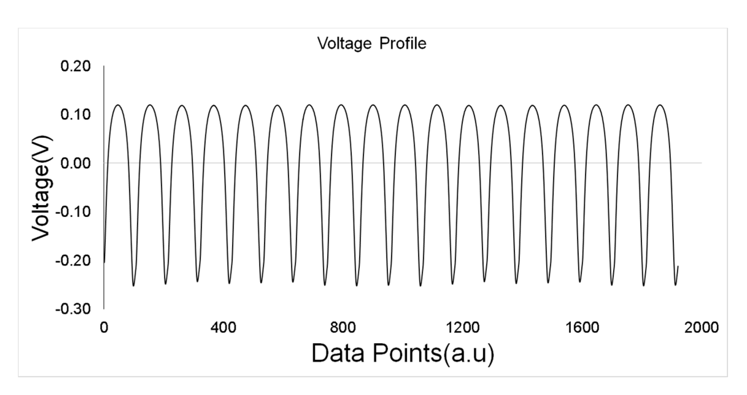
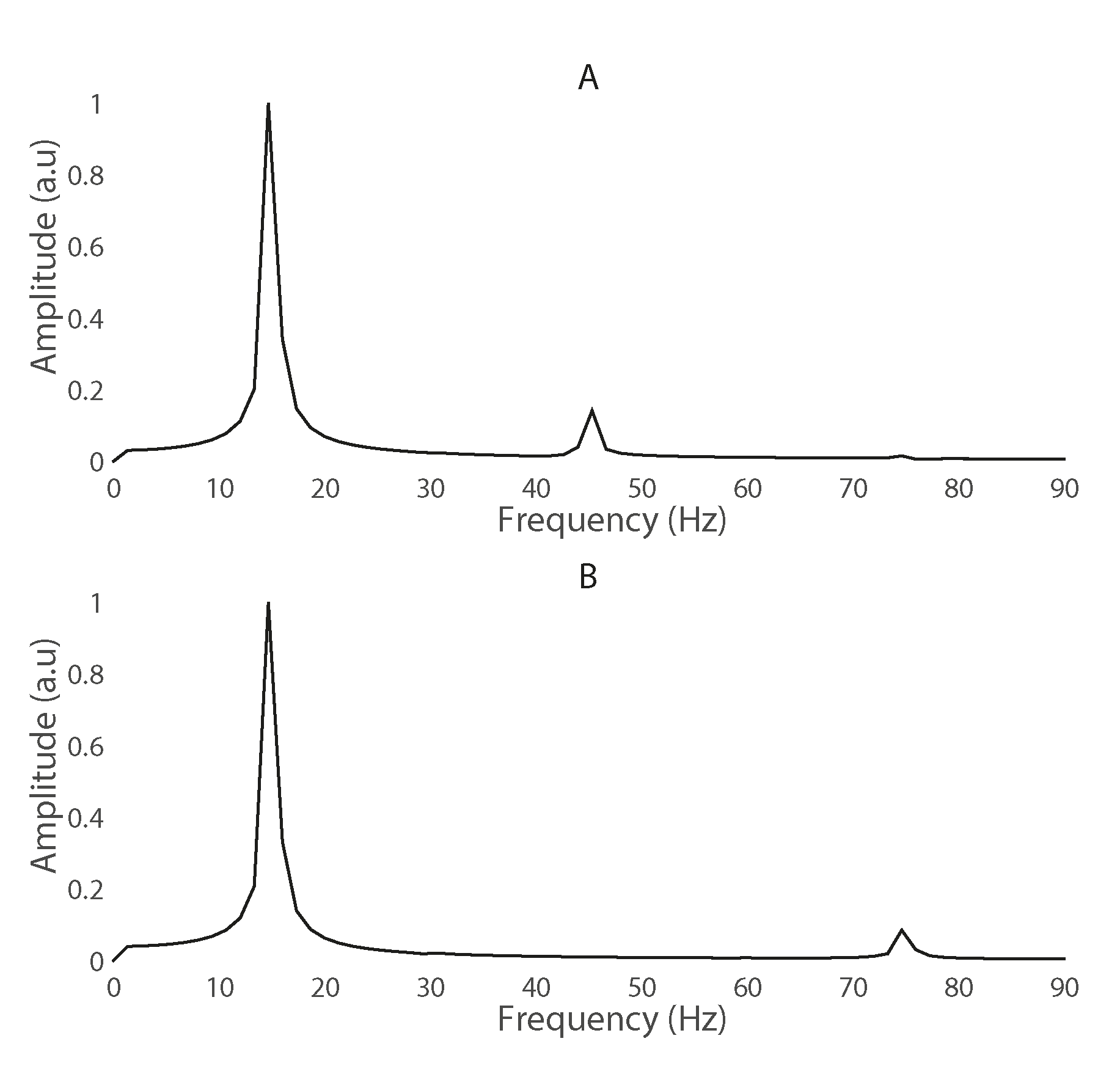
4.2 Total Harmonic Distortion
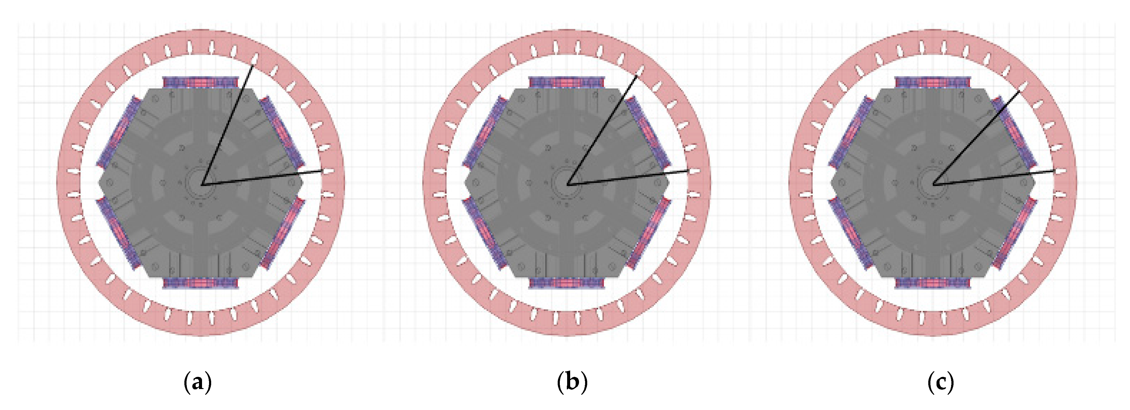
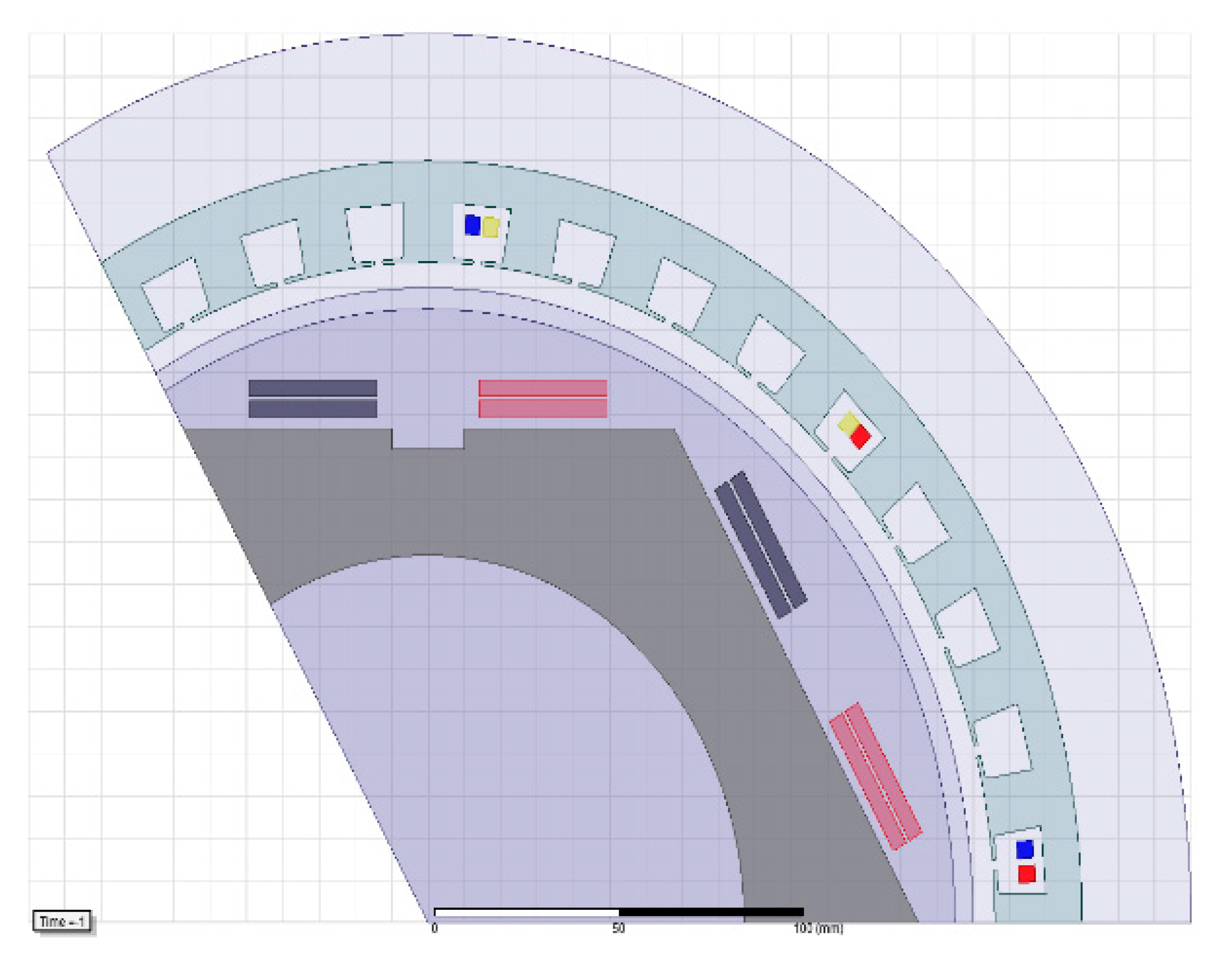
4.3 Stator Design Improvement
4.3.1. Stator Design 1
4.3.2. Stator Design 2
- Stator slot width, and
- Internal diameter of the rotor.
5. Conclusions
Acknowledgments
Author Contributions
Conflicts of Interest
References
- Kalsi, S.S. Application of High Temperature Superconductors to Electric Power Equipment; John Wiley & Sons: Hoboken, NJ, USA, 2011. [Google Scholar]
- Qu, R.; Liu, Y.; Wang, J. Review of Superconducting Generator Topologies for Direct-Drive Wind Turbines. IEEE Trans. Appl. Supercond. 2013, 23, 5201108. [Google Scholar]
- Kalsi, S.S.; Henderson, N.; Gritter, D.; Nayak, O.; Gallagher, C. Benefits of HTS technology to ship systems. In Proceedings of the IEEE Symposium on Electric Ship Technologies, Philadelphia, PA, USA, 27 July 2005. [Google Scholar]
- Kalsi, S.S.; Weeber, K.; Takesue, H.; Lewis, C.L.; Neumueller, H.W.; Blaugher, R.D. Development status of rotating machines employing superconducting field windings. Proc. IEEE. 2004, 92, 1688–1704. [Google Scholar] [CrossRef]
- Nick, W.; Nerowski, G.; Neumüller, H.W.; Frank, M.; Van Hasselt, P.; Frauenhofer, J.; Steinmeyer, F. 380 kW synchronous machine with HTS rotor windings—Development at Siemens and first test results. Phys. C Supercond. 2002, 372–376, 1506–1512. [Google Scholar] [CrossRef]
- Barnes, P.N.; Sumption, M.D.; Rhoads, G.L. Review of high power density superconducting generators: Present state and prospects for incorporating YBCO windings. Cryogenics 2005, 45, 670–686. [Google Scholar] [CrossRef]
- Jeong, S.; Kim, Y. Thermal anchoring of conduction-cooled current leads for superconductivity applications near liquid nitrogen temperature. Cryogenics 2010, 50, 287–291. [Google Scholar] [CrossRef]
- Bumby, C.W.; Pantoja, A.E.; Sung, H.J.; Jiang, Z.; Kulkarni, R.; Badcock, R.A. Through-Wall Excitation of a Magnet Coil by an External-Rotor HTS Flux Pump. IEEE Trans. Appl. Supercond. 2016, 26, 1–5. [Google Scholar] [CrossRef]
- Kulkarni, R.; Prasad, K.; Lie, T.T. Flux pump for HTS rotating machinery applications. In Proceedings of the 2015 IEEE Eindhoven PowerTech 2015, Eindhoven, The Netherlands, 29 June–2 July 2015. [Google Scholar]
- Nakamura, T.; Sugano, M.; Doi, T.; Amemiya, N. Flux Pumping Effect of HTS Films in a Traveling Magnetic Field. IEEE Trans. Appl. Supercond. 2010, 20, 1033–1036. [Google Scholar] [CrossRef]
- Ishmael, S.; Goodzeit, C.; Masson, P.; Meinke, R.; Sullivan, R. Flux Pump Excited Double-Helix Rotor for Use in Synchronous Machines. IEEE Trans. Appl. Supercond. 2008, 18, 693–696. [Google Scholar] [CrossRef]
- Hoffmann, C.; Walsh, R.; Karrer-Mueller, E.; Pooke, D. Design Parameters for an HTS Flux Pump. Phys. Procedia 2012, 36, 1324–1329. [Google Scholar] [CrossRef]
- Hoffmann, C.; Pooke, D.; Caplin, A.D. Flux Pump for HTS Magnets. IEEE Trans. Appl. Supercond. 2011, 21, 1628–1631. [Google Scholar] [CrossRef]
- Coombs, T.; Hong, Z.; Zhu, X. A thermally actuated superconducting flux pump. Phys. C Supercond. 2008, 468, 153–159. [Google Scholar] [CrossRef]
- Jiang, Z.; Hamilton, K.; Amemiya, N.; Badcock, R.A.; Bumby, C.W. Dynamic resistance of a high-Tc superconducting flux pump. Appl. Phys. Lett. 2014, 105, 112601. [Google Scholar] [CrossRef]
- Bumby, C.W.; Badcock, R.A.; Sung, H.J.; Kim, K.M.; Jiang, Z.; Pantoja, A.E.; Buckley, R.G. Development of a brushless HTS exciter for a 10 kW HTS synchronous generator. Supercond. Sci. Technol. 2016, 29, 024008. [Google Scholar] [CrossRef]
- Mawardi, O.; Muelder, S.; Michelotti, R. Brushless superconducting alternators. IEEE Trans. Magn. 1977, 13, 780–783. [Google Scholar] [CrossRef]
- Muta, I.; Tsukiji, H.; Hoshino, T.; Mukai, E. Electrical characteristics of fully superconducting synchronous generator in persistent excitation mode. IEEE Trans. Magn. 1992, 28, 434–437. [Google Scholar] [CrossRef]
- Muta, I.; Tsukiji, H.; Hoshino, T.; Mukai, E. Output power limit of 200 MW class brushless superconducting generator excited with magnetic flux-pump. IEEE Trans. Appl. Supercond. 2001, 11, 2335–2338. [Google Scholar]
- Ferendeci, A.; Mawardi, O.; Melfi, M.; Laquer, H. Flux pump excited brushless alternator. IEEE Trans. Magn. 1981, 17, 146–148. [Google Scholar] [CrossRef]
- Vashi, A. Harmonic Reduction in Power System. Master’s Degree, California State University, Sacramento, CA, USA, 8 June 2010. [Google Scholar]
- Wakileh, G.J. Harmonics in rotating machines. Electr. Power Syst. Res. 2003, 66, 31–37. [Google Scholar] [CrossRef]
- Miller, T.J.E.; Hughes, A. Comparative design and performance analysis of air-cored and iron-cored synchronous machines. Proc. Inst. Electr. Eng. 1977, 124, 127–132. [Google Scholar] [CrossRef]
- Hughes, A.; Miller, T.J.E. Analysis of fields and inductances in air-cored and iron-cored synchronous machines. Proc. Inst. Electr. Eng. 1977, 124, 121–126. [Google Scholar] [CrossRef]
- Kulkarni, R.; Prasad, K.; Lie, T.T.; Badcock, R.A.; Bumby, C.W.; Sung, H.J. FEM and performance analysis of 10 kW HTS generator with flux pump excitation. In Proceedings of the 2016 IEEE International Conference on Power System Technology (POWERCON), Wollongong, Australia, 28 September–1 October 2016. [Google Scholar]
- Khalf, M.A.; Wamkeue, R.; Aguglia, D. Finite element approach for performances prediction of a small synchronous generator using ANSYS software. In Proceedings of the 25th IEEE Canadian Conference on Electrical & Computer Engineering (CCECE), Montreal, QC, Canada, 29 April–2 May 2012. [Google Scholar]
- ANSYS Maxwell Manual. Available online: https://support.ANSYS.com/portal/site/ANSYSCustomerPortal/template.fss?file=%2Fsolutions%2Fattach%2FMAXWELL.pdf (accessed on 29 August 2017).
- Shafaie, R.; Kalantar, M. Design of a 10-MW-Class Wind Turbine HTS Synchronous Generator with Optimized Field Winding. IEEE Trans. Appl. Supercond. 2013, 23, 5202307. [Google Scholar] [CrossRef]
- Seo, J.H.; Han, K.J.; Choi, H.S.; Lee, S.H.; Hahn, S.; Lee, H. Comparison Study on Harmonic Loss of MW-Class Wind Generators with HTS Field Winding. IEEE Trans. Appl. Supercond. 2014, 24, 1–5. [Google Scholar] [CrossRef]
- Technical Note. Available online: library.e.abb.com/public/8d5deb3fe4638051c1257c9400508282/Technical%20note%20Winding%20pitch%20LR_040214.pdf (accessed on 25 August 2017).
- Nelson, J.P. A better understanding of harmonic distortion in the petrochemical industry. IEEE Trans. Ind. Appl. 2004, 40, 220–231. [Google Scholar] [CrossRef]
- Butcher Charles, A. Synchronous Machine Starting System. U.S. Patent 1,804,591, 12 May 1931. [Google Scholar]
- Zhang, L.; Huang, Y.; Dong, J.; Guo, B.; Zhou, T. Stator winding design of induction motors for high efficiency. In Proceedings of the 17th International Conference on Electrical Machines and Systems (ICEMS), Hangzhou, China, 22–25 October 2014. [Google Scholar]
- Smith, R.; Layton, J.M. Harmonic elimination in poly-phase machines by graded windings. Proc. Inst. Electr. Eng. 1963, 110, 1640–1648. [Google Scholar] [CrossRef]
- Alternator Winding Pitch and Power System Design. Available online: https://power.cummins.com/technical-papers (accessed on 29 August 2017).
- Say, M.G. Alternating Current Machines, 4th ed.; Pitman Publishing Ltd.: London, UK, 1976. [Google Scholar]
- Zhang, Z.; Molinas, M.; Matveev, A.; Nilssen, R.; Nysveen, A. Efficiency calculation and improvement of a large-diameter ironless permanent magnet generator. In Proceedings of the 2012 15th International Conference on Electrical Machines and Systems (ICEMS), Sapporo, Japan, 21–24 October 2012. [Google Scholar]


| Parameter | Value |
|---|---|
| Rating | 10 kW |
| HTS Coil Temperature | 30K |
| Rated Voltage | 400 V |
| Poles | 6 |
| Speed | 300 rpm |
| Frequency | 15 Hz |
| Type of Rotor | HTS |
| HTS Winding | Racetrack |
| HTS Wire | SuNam |
| Coil Thickness | 35.25 mm |
| Turns in field coil | 235 |
| Rated field current | 98 A |
| Field current margin | 40% |
| Rotor shaft length | 315 mm |
| Total diameter | 497 mm |
| Boundary Conditions | Vector Potential & Master Slave |
|---|---|
| Mesh type | Length based |
| Analysis type | Magnetic transient |
| Time step | 0.2 ms |
| Total simulation time | 750 ms |
| Winding Pitch Factor (Kp) | ||
|---|---|---|
| Component | 2/3 Pitch | 5/6 Pitch |
| Fundamental | 0.87 | 0.97 |
| 3rd Harmonic | 0.00 | 0.71 |
| 5th Harmonic | 0.87 | 0.26 |
| 7th Harmonic | 0.87 | 0.26 |
| f (Hz) | Pitch = 5/6 | Pitch = 2/3 | ||
|---|---|---|---|---|
| Steel | G10 | Steel | G10 | |
| 60 | 15.56 | 13.40 | 8.59 | 6.13 |
| 120 | 15.56 | 13.41 | 8.60 | 6.14 |
| 240 | 15.57 | 13.41 | 8.61 | 6.14 |
| f (Hz) | Star-Star | Star-Delta |
|---|---|---|
| 60 | 5.91 | 5.21 |
| 120 | 5.91 | 5.22 |
| 240 | 5.98 | 5.22 |
| f (Hz) | THD (Vph) | ||
|---|---|---|---|
| Rated Load | 1/2 Rated Load | 1/4 Rated Load | |
| 60 | 5.21 | 5.84 | 6.05 |
| 120 | 5.22 | 5.84 | 6.05 |
| 240 | 5.22 | 5.84 | 6.05 |
| f (Hz) | No Load THD | Rated Load THD | ||
| Design 1 | Design 2 | Design 1 | Design 2 | |
| 60 | 6.1367 | 4.2915 | 5.2164 | 2.7269 |
| 120 | 6.1378 | 4.3016 | 5.2196 | 2.7366 |
| 240 | 6.1383 | 4.3155 | 5.2243 | 2.7398 |
© 2017 by the authors. Licensee MDPI, Basel, Switzerland. This article is an open access article distributed under the terms and conditions of the Creative Commons Attribution (CC BY) license (http://creativecommons.org/licenses/by/4.0/).
Share and Cite
Kulkarni, R.; Prasad, K.; Tjing Lie, T.; Badcock, R.A.; Bumby, C.W.; Sung, H.-J. Design Improvisation for Reduced Harmonic Distortion in a Flux Pump-Integrated HTS Generator. Energies 2017, 10, 1344. https://doi.org/10.3390/en10091344
Kulkarni R, Prasad K, Tjing Lie T, Badcock RA, Bumby CW, Sung H-J. Design Improvisation for Reduced Harmonic Distortion in a Flux Pump-Integrated HTS Generator. Energies. 2017; 10(9):1344. https://doi.org/10.3390/en10091344
Chicago/Turabian StyleKulkarni, Ravichandra, Krishnamachar Prasad, Tek Tjing Lie, Rodney A. Badcock, Chris W. Bumby, and Hae-Jin Sung. 2017. "Design Improvisation for Reduced Harmonic Distortion in a Flux Pump-Integrated HTS Generator" Energies 10, no. 9: 1344. https://doi.org/10.3390/en10091344
APA StyleKulkarni, R., Prasad, K., Tjing Lie, T., Badcock, R. A., Bumby, C. W., & Sung, H.-J. (2017). Design Improvisation for Reduced Harmonic Distortion in a Flux Pump-Integrated HTS Generator. Energies, 10(9), 1344. https://doi.org/10.3390/en10091344