Review

Overview of AC Microgrid Controls with Inverter-Interfaced Generations

1
School of Engineering & Information Technology, The University of New South Wales, Canberra, ACT 2610, Australia
2
Department of Engineering and Mathematics, Sheffield Hallam University, Sheffield S1 1WB, UK
3
Department of Engineering, Macquarie University, Sydney, NSW 2109, Australia
*
Author to whom correspondence should be addressed.
Energies 2017, 10(9), 1300; https://doi.org/10.3390/en10091300
Submission received: 18 July 2017 / Revised: 24 August 2017 / Accepted: 24 August 2017 / Published: 30 August 2017

Abstract

:
Distributed generation (DG) is one of the key components of the emerging microgrid concept that enables renewable energy integration in a distribution network. In DG unit operation, inverters play a vital role in interfacing energy sources with the grid utility. An effective interfacing can successfully be accomplished by operating inverters with effective control techniques. This paper reviews and categorises different control methods (voltage and primary) for improving microgrid power quality, stability and power sharing approaches. In addition, the specific characteristics of microgrids are summarised to distinguish from distribution network control. Moreover, various control approaches including inner-loop controls and primary controls are compared according to their relative advantages and disadvantages. Finally, future research trends for microgrid control are discussed pointing out the research opportunities. This review paper will be a good basis for researchers working in microgrids and for industry to implement the ongoing research improvement in real systems.

1. Introduction

Due to the exhaustion of conventional energy sources and growing electricity demand, electric power systems are incorporating alternative renewable energy sources (RESs) including photovoltaic (PV) systems, wind energy systems, fuel cells, and micro-turbines [1,2,3]. These RESs are connected to the distribution network in the form of distributed generations (DGs) as shown in Figure 1. As the frequency of the power generated from RESs is not the same as that of the traditional power system, power electronic converters (PECs) are employed as interfacing devices to synchronise to the device with the network. In PECs, voltage source inverters (VSIs) are used as the last step of the conversion process to produce ac voltage. The VSIs regulate voltage, frequency and power output to the network while fulfilling the grid requirements [4].
The operation and control strategies of an inverter can vary depending on the types of loads and the modes of microgrids. Until now, no standard control and operation strategies have been set by any institution/organisation for inverter-interfaced microgrids, and it may not be possible to do so. The majority of the published literature reviews on the control and operation of DG units focus on the primary control strategies due to their power sharing challenges [5,6,7]. Therefore, this paper is intended to present a comprehensive review of the different control levels of a hierarchical grid-forming DG units and show recent progress on the control strategies to enable a better understanding of the inverter control and operation.
The rest of the paper is organised as follows. In Section 2, an overview of DG units is briefly discussed. Section 3 describes the characteristics of microgrids and modes of microgrid operation, namely, a grid-connected and an islanded mode. In Section 4, a hierarchical control approach for grid-forming DG units is depicted. The control strategies in various reference frames are illustrated in Section 5. Section 6 presents different inner-loop control methods of an inverter and highlights their relative advantages and disadvantages. In Section 7, communication-less control for power sharing strategies are demonstrated with the pros and cons of each method. Section 8 discusses possible future research opportunities on microgrid control.

2. Overview of DG Units

A typical DG unit consisting of an energy source, a conversion system and an output filter is shown in Figure 2. In the energy source block, power is converted to electric dc form through different intermediate stages including dc/dc conversion. These sources are divided into two categories, namely renewable and non-renewable. Renewable sources include wind, solar, geothermal, and biomass; where non-renewable sources are coal, diesel, furnace oil, natural gas, and fuel cells.
In between the energy source and the inverter, a capacitor bank is often connected to realise a dc interface. The main functions of the capacitor bank are to reduce voltage ripple, stabilise the dc-link voltage and supply/absorb energy for a short period during disturbances, such as load changing events. In addition, the capacitor assists slightly in balancing power difference between the energy source and inverter input [8,9]. The placement of the capacitor at the dc busbar plays a vital role in controlling the inverter.
Power semiconductor components are fundamental elements of inverters [10]. Inverters are often constructed with insulated-gate bipolar transistors (IGBTs) and diodes connected in the reverse direction, which allow bidirectional power flow, shown in Figure 2. The preference for using IGBTs over metal-oxide-semiconductor field-effect transistors (MOSFETs) is that it offers greater power gain with lower power losses, higher voltage operation, and higher allowable junction temperature. The dc voltage at the dc busbar is converted into pulsating ac voltage by the inverter. An LC filter following the inverter is used to attenuate the high frequency harmonics from the output. The pulsating ac is generated because of the turning on and off sequences of the IGBT gates and change in the direction of the dc power flow. These sequences are typically calculated by pulse width modulation (PWM) which is adjusted by the current/voltage controller taking feedbacks from the LC filter current and voltage. This filter enhances the power quality of an inverter output by eliminating ripple waves, i.e., harmonics, and consequently, it can assist in coordinating multiple DG units by proper selection of the LC parameters. The practical implementation of inverters and their related controls are available in [11].
Two principal operations of inverters are determined in a microgrid operation: grid-following and grid-forming. The grid-following operating mode, sometimes denoted as grid feeding and PQ control [12,13], is achieved by current source inverters (CSIs). In the grid-forming operation, voltage source inverters (VSIs) are usually employed to control the voltage and frequency of a network. Both the grid-forming and grid-following units utilise VSIs. It just adopts different control algorithms based on the mode changes.

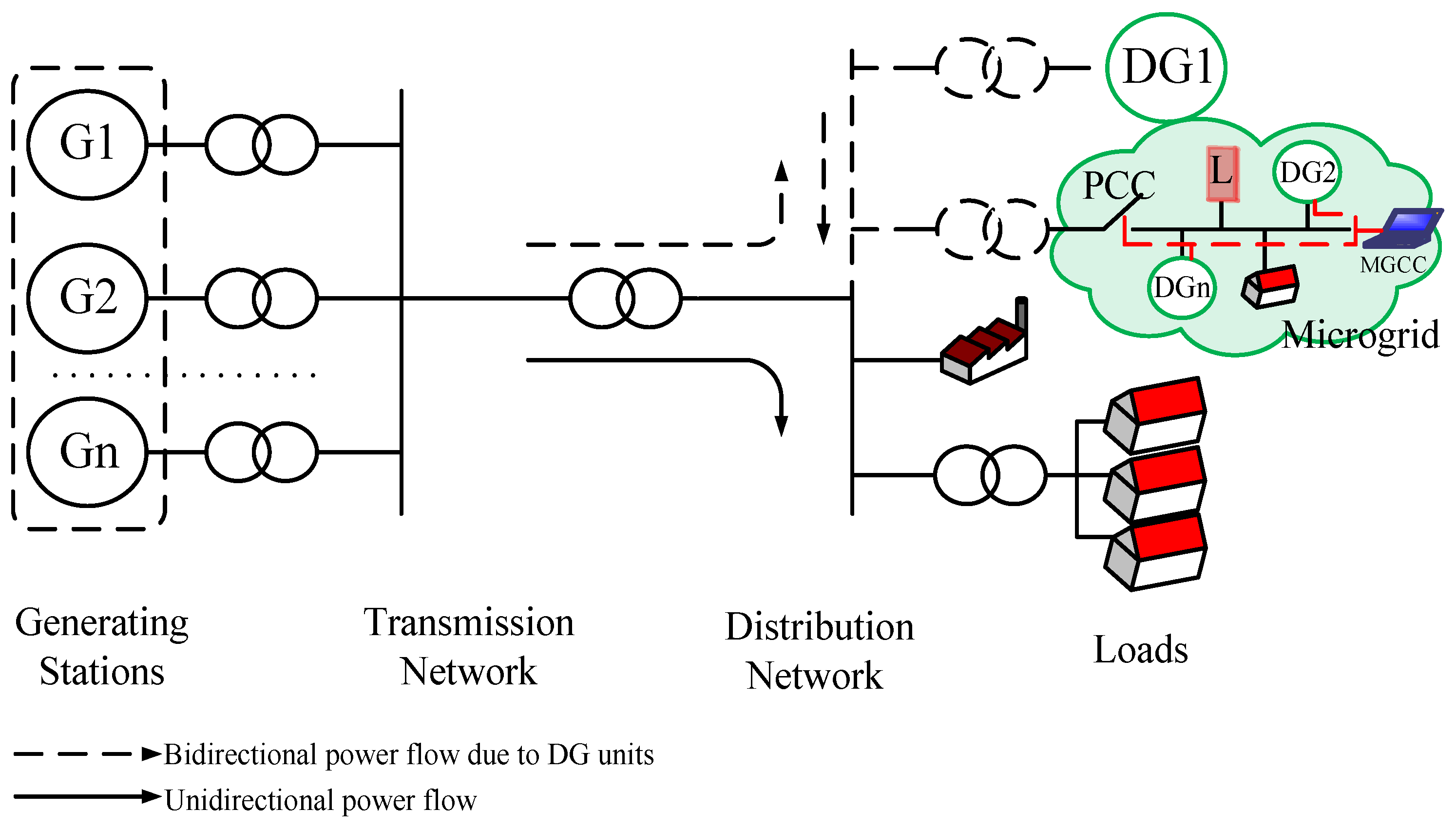
3. Microgrid Characteristics and Operation

3.1. Characteristics of Microgrids

The high penetration of DG units in a distribution network causes several technical and operational issues, including power quality, network stability, low inertia, and network voltage and fault level change. To overcome the above issues, a microgrid concept has evolved [14,15,16]. However, the notion of microgrids is often confused with distribution network control. The key differences with a microgrid are that it has a central control unit with a specific region and a point of common coupling (PCC) to connect and disconnect the microgrid with the grid utility. The features of a typical microgrid [12,17,18] are summarised as follows.
  • It supervises the electrical components, such as powers, voltages and frequencies by means of monitors.
  • It has a PCC in a distribution network for connecting and disconnecting the grid utility.
  • It is a subset of LV or medium-voltage (MV) distribution networks.
  • It consists of generation units, a hierarchical control approach, power consumption places and energy storage systems.
  • It facilitates an uninterrupted power supply to, at least, the highest priority loads during a grid failure or power quality degradation.
  • It has two operating modes: (1) grid-connected; and (2) islanded or standalone (autonomous).
  • It acts as a single controllable entity from the grid perspective.
  • It generates the required reference voltage and frequency in an islanded operation.
  • It is constructed in a defined location which can be in a distribution network or remote area.
  • It has the necessary protection schemes.
  • It controls the power supply during both grid-connected and islanding operations.
  • It accumulates DG units, the ratings of which are less than 100 MW.
  • It displays ‘plug and play’ features and ‘peer to peer’ functionality.
  • It adjusts to abnormal situations (unintentional islanding or faults).
  • It uses local information to control the power flow of DG units.
  • It can possess ac and/or dc distribution networks.
  • It may provide electrical energy and thermal energy (heat and/or cool) simultaneously.
Considering the above characteristics, a microgrid can be defined as follows: A microgrid (consisting of small-scale emerging generators, loads, energy storage elements, and control units) is a controlled small-scale power system that can be operated in an islanded and/or grid-connected mode, serving within a defined area to facilitate power supplementation and/or improved power quality to the consumer’s premises.

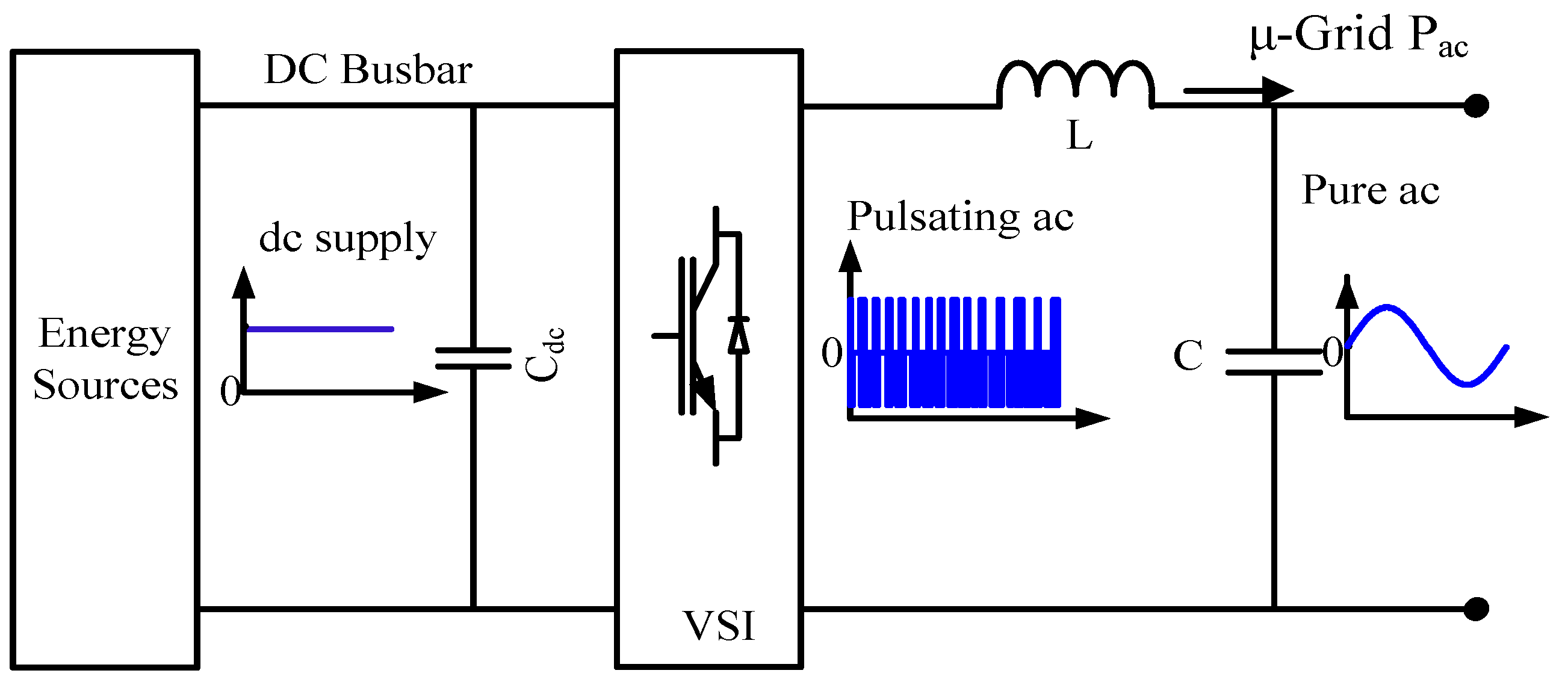
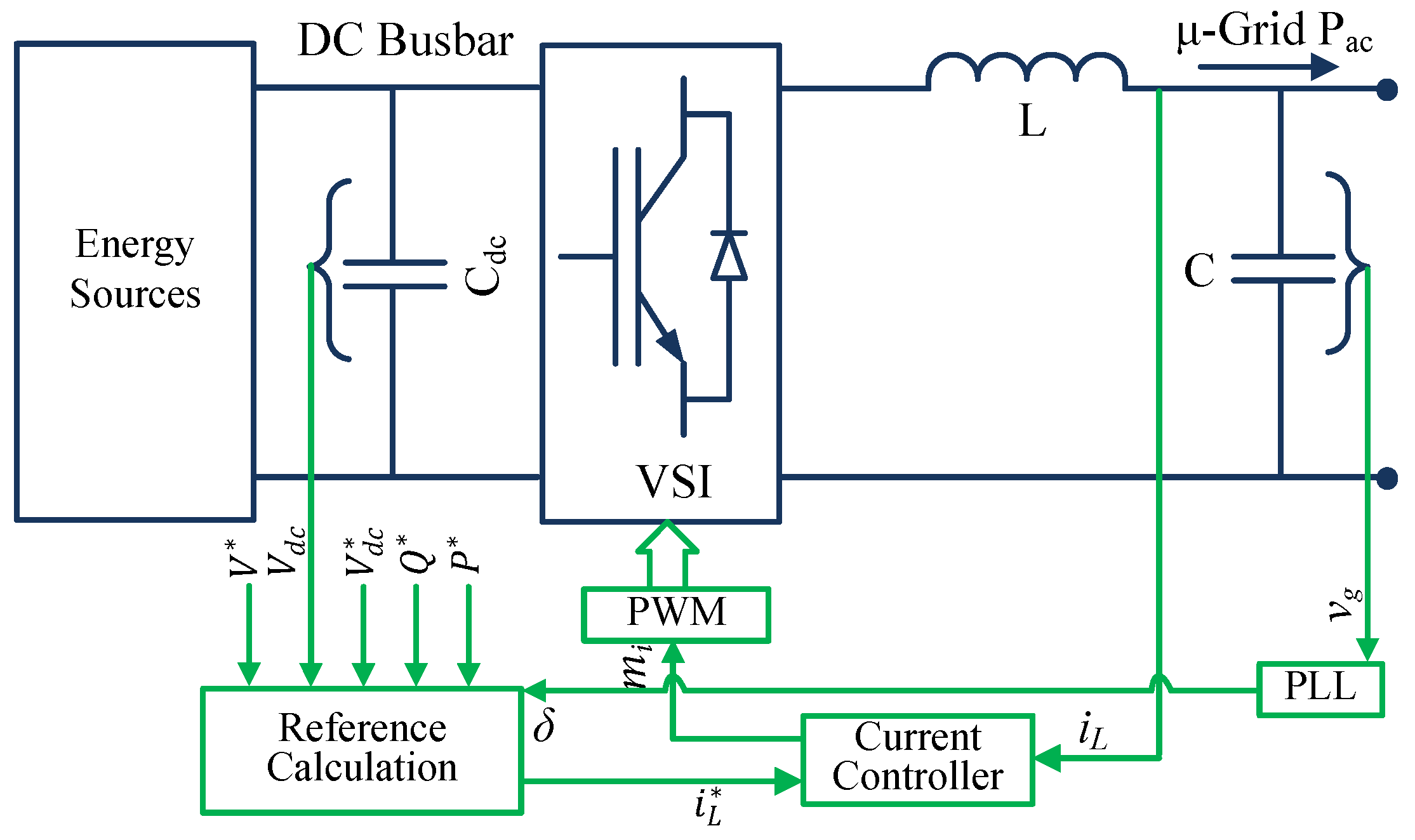
3.2. Grid-Connected Operation

The aim of the grid-connected inverter is to export controllable power with the established voltage. The generated power is controlled by the in-phase current component which is proportional to the network power demand. The supervisory controller (SC), receiving power demand information from short-term/long-term prediction values, operates DG units either in a constant power output or in a load-following manner [19]. In Figure 3, the power set-points generate a current reference for the current regulator. The closed-loop controller ensures that the output current tracks the reference value with a zero steady-state error.
Figure 3 shows a block diagram of a grid-connected inverter control strategy, where the closed-loop current controller enables output power delivery by calculating an error signal from measured and commanded signals. The reference current is determined from the set values of the controller. Each inverter is responsible for controlling its output current and power according to a power demand set by the supervisory controller. The inverter power quality can be influenced by the background network harmonics. However, the quality can be improved by properly designing the controller and filter [20,21].
Some of the desired features of the inner-loop current control are as follows: (1) accurate current control; (2) high bandwidth; (3) fast dynamic response, 4–6 times faster than that of the outer voltage controller; (4) low current distortion, and filter resonance damping. These characteristics are achieved with the different control techniques for various microgrid models [22,23].

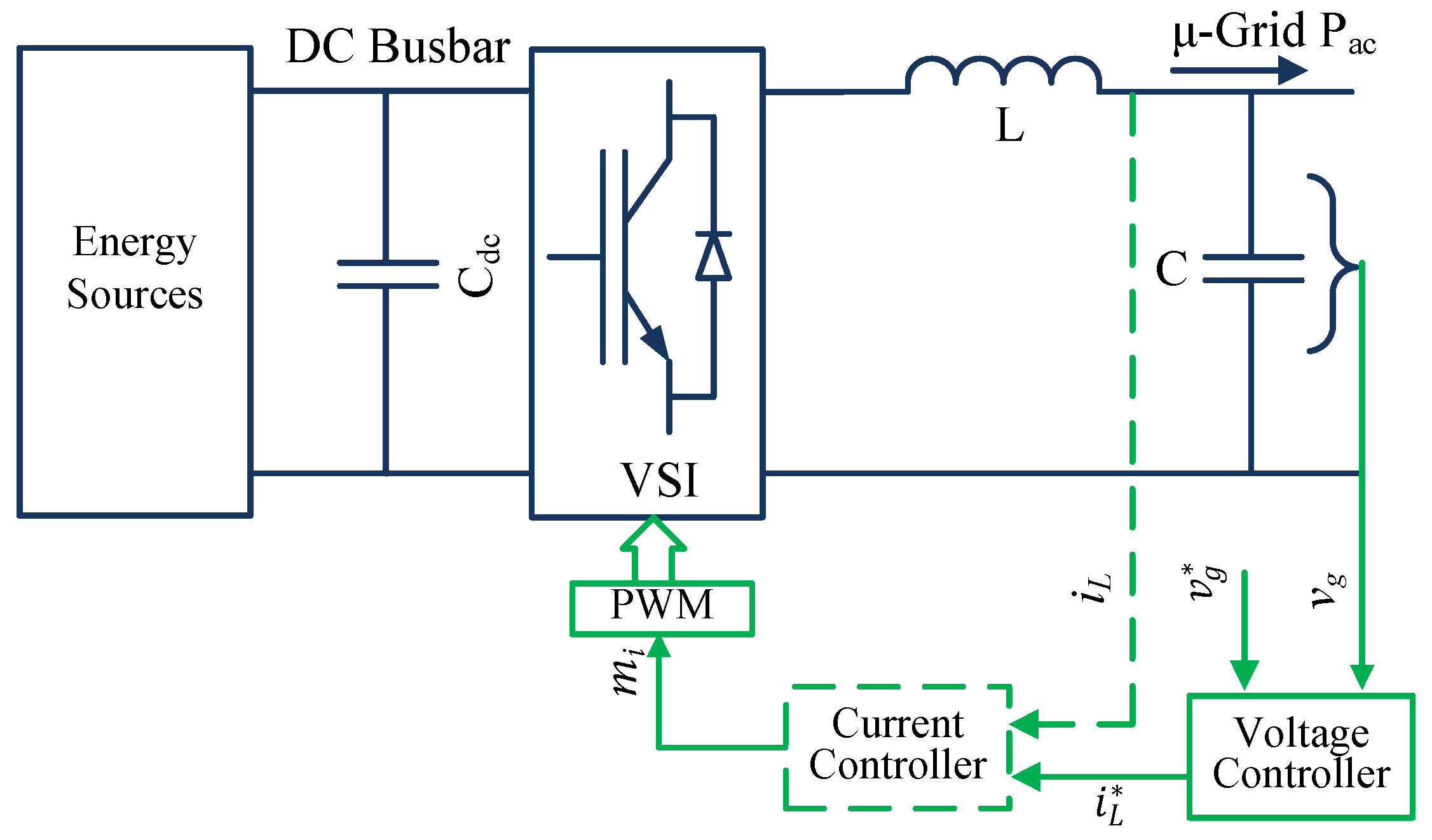
3.3. Islanded Operation

The lack of the grid utility supply to a microgrid operation necessitates establishing the reference voltage and frequency. Therefore, DG units operated in an islanded microgrid are responsible for ensuring the reference voltage and frequency, which are the main functions of the inverters [4,24]. The simple diagram of a VSI control, without considering current control loop illustrated in dashed lines, is shown in Figure 4, although some of its shortcomings are reported in [10] as follows.
  • The absence of a current control can lead to a large transient current that may damage semiconductor components during faults.
  • The voltage measurement across the capacitor may not provide accurate information regarding the network.
Considering the drawback of a simple VSI control, an alternative cascaded control strategy (both the voltage and current controls) can be applied shown in Figure 4. The response time of the current control loop, forming round the inductor, is comparatively lower than the voltage control loop, which facilitates faster current control response. The advantage of this strategy is that excessive current can be limited in the voltage control loop. The reference current provided from the voltage control loop can be also used in other parallel modules as a reference current for power sharing purposes. In this case, the plants should be in close proximity; otherwise, communication lines with a bandwidth 100 kb/s are required to retain a controller performance [19].
If the voltage controller alone is used in the inner-loop control, some of the desired characteristics are expected [25] as follows: (1) high loop gain at dc for regulating the voltage magnitude with a minimum error; (2) high bandwidth to eliminate harmonics; (3) high loop gain at the fundamental frequency to restrain imbalance; (4) robust performance in the presence of plant model uncertainty; (5) fast response with the lowest overshoot; (6) negligible coupling between the active and reactive powers and (7) highly stable to any non-linear network attitude.
It is worth mentioning that, in voltage source inverters, the inner-loop current control is not required, generally, to control the voltage. However, the implementation of the current control in a voltage control loop improves the inverter performance and confirms current limitations.

3.4. Miscellaneous DG Operation

If both inverter-based DG units and conventional synchronous generators deliver power in a microgrid, two possible solutions of connecting DG units can be implemented. If a high penetration of inverter-based DG units exists, synchronous generators can be operated as current/power sources synchronising with the inverters which dominate the bus voltage and frequency control. In contrast, if a number of synchronous machines are higher than inverter-based DG units, the control approaches of inverter-connected DG units will be employed as a grid-connected operation [26].

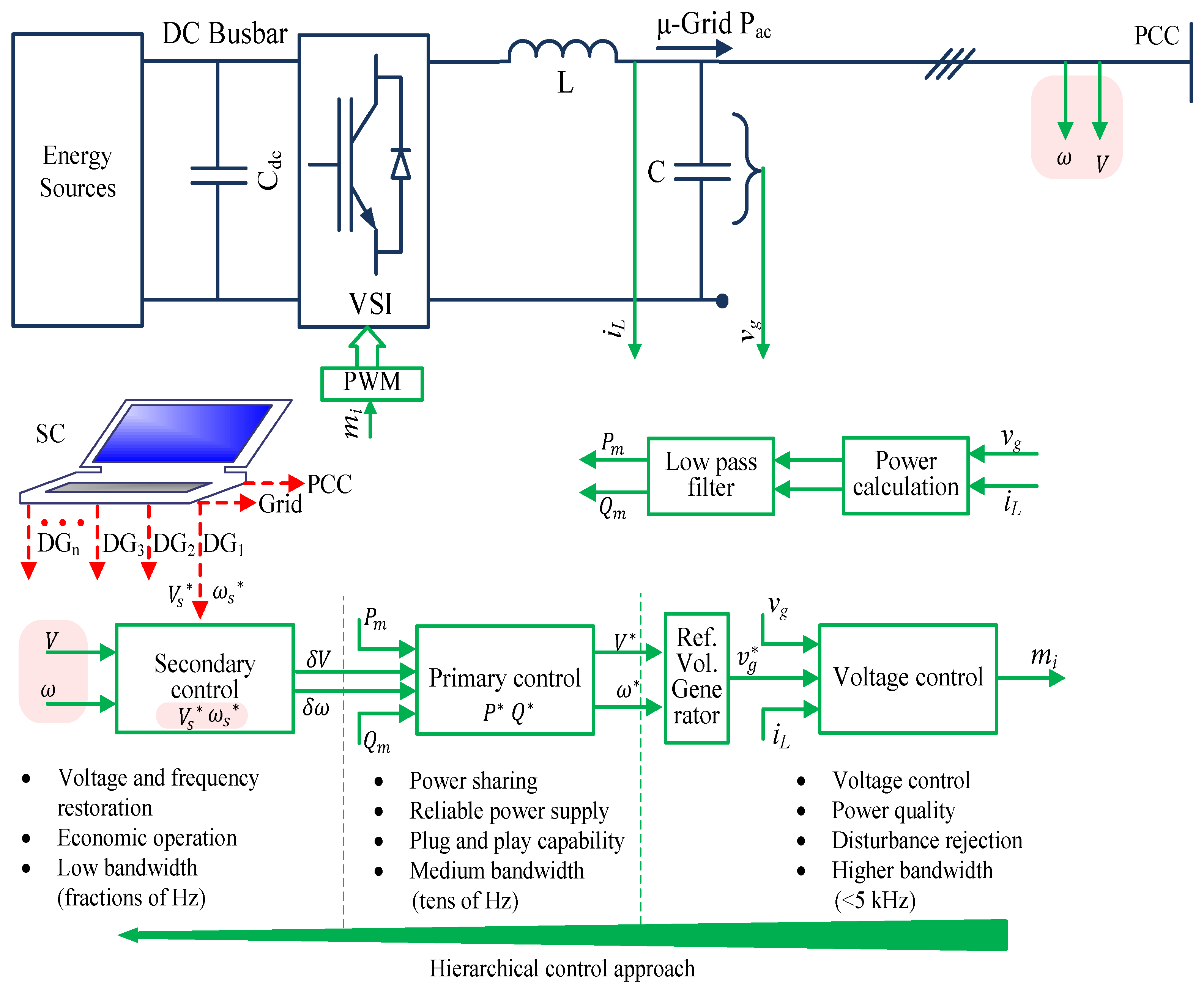
4. Hierarchical Control of DG Units

Sustainable control approaches are essential to operating microgrids in a stable and economically viable way [12,14,27]. The main activities in a microgrid are the voltage and frequency regulations, load sharing and DG coordination, power flow control, cost optimisation, and power generation and demand prediction. These requirements necessitate a hierarchical control structure for a microgrid operation [28]. The hierarchical control structure for grid-forming DG units in an islanded microgrid is divided into three levels, namely, voltage control, primary control, and secondary/tertiary control shown in Figure 5. The reason for categorising three levels is that islanded microgrids are situated in a small region unlike the conventional power system, although, in some studies, this hierarchical structure is divided into four levels. The extra control layer increases initial investment and operating cost which may not be economically viable for an islanded microgrid.
The voltage control is responsible for the instantaneous reference grid voltage tracking and power quality issues [7]. The voltage control loop includes either an inner-loop voltage control or both the voltage and current control loops—often known as a cascaded control [24]. These loops may contain feedback, feed forward, virtual impedance, and linear and non-linear control loops to regulate the inductor current and/or capacitor voltage properly. Moreover, this level contains higher bandwidth compared to the others to guarantee the microgrid stability with a fast response under any disturbance. For instance, the current control can be constructed as 20 kHz bandwidth and the voltage control as 5 kHz, which is much higher than a bandwidth of the primary control. The reference value of the voltage control is determined by the mid-level primary control.
The primary control in microgrids has several roles, including: enhancing system performance and stability, maintaining the voltage and frequency stability, offering plug and play features of DG units, ensuring accurate power sharing in the presence of linear and non-linear loads, and eliminating circular current [28,29,30,31]. This control loop can be designed based on either communication or communication-less; however, the latter one, which is based on local measurements, is preferable to improve microgrid reliability. The bandwidth of this control is typically tens of Hz depending on the control design, for example, it can be 30 Hz which is much lower than the inner-loop control.
The reference values of the primary control can be changed by the secondary/tertiary control. This control level measures the voltage and frequency at the PCC or at a large reference generator, and compares the values with ω s * and V s * to generate error signals for restoring the commanded values [32,33,34]. The controller decouples the control parameters and creates a management system for frequency and voltage restoration, reactive power compensation, mode transfer, power settings, voltage regulation, and power sharing. In addition, secondary/tertiary control predicts the power generation and demand to determine the optimum operation points for DG units. The controller also takes care of the microgrid synchronisation with the grid utility. The secondary/tertiary controller—sometimes referred to a supervisory controller or microgrid central control (MGCC)—is designed based on optimisation algorithms and economical issues. This control level generally uses low-bandwidth (such as 3 Hz) communication lines for communication purposes.

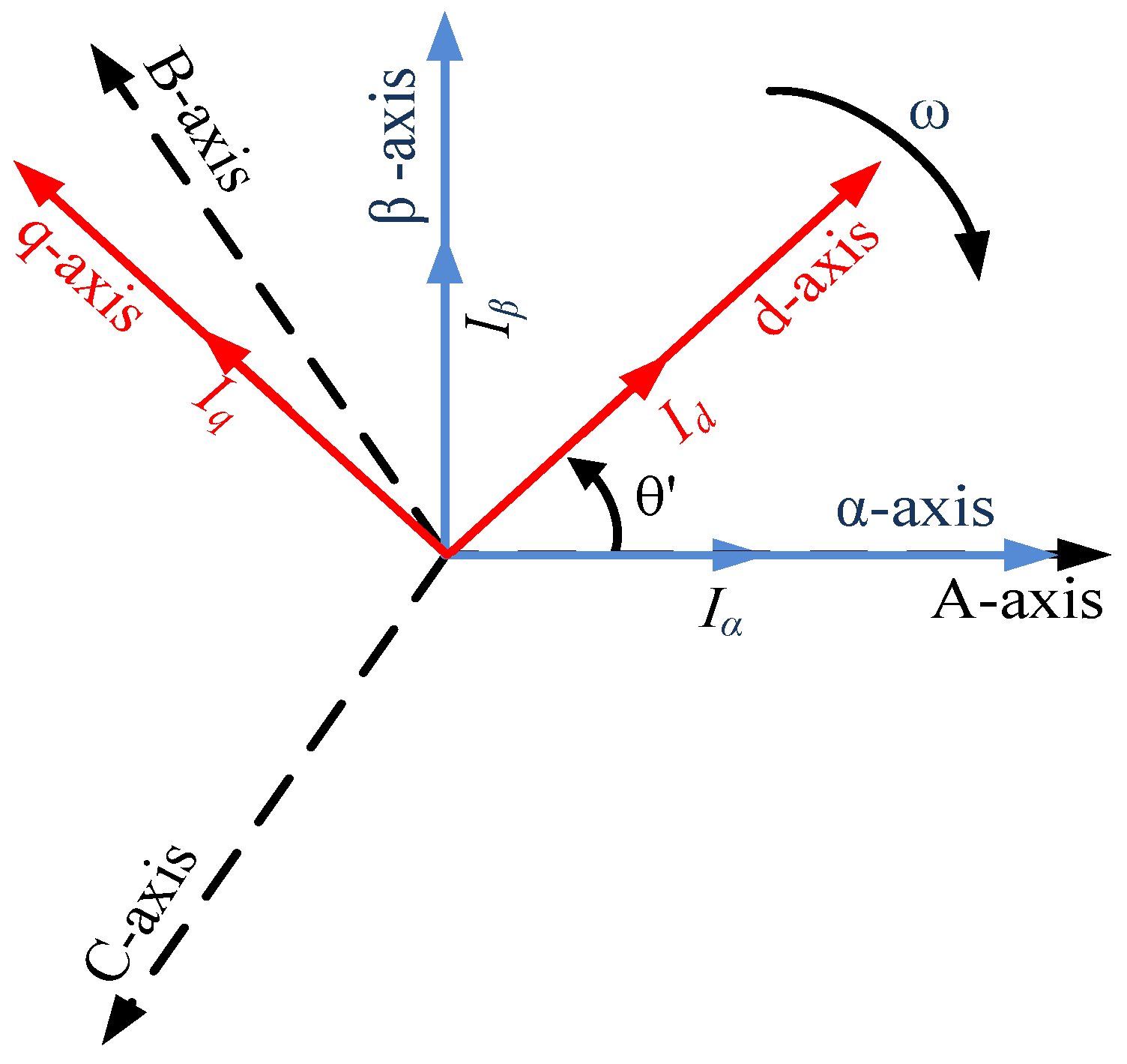
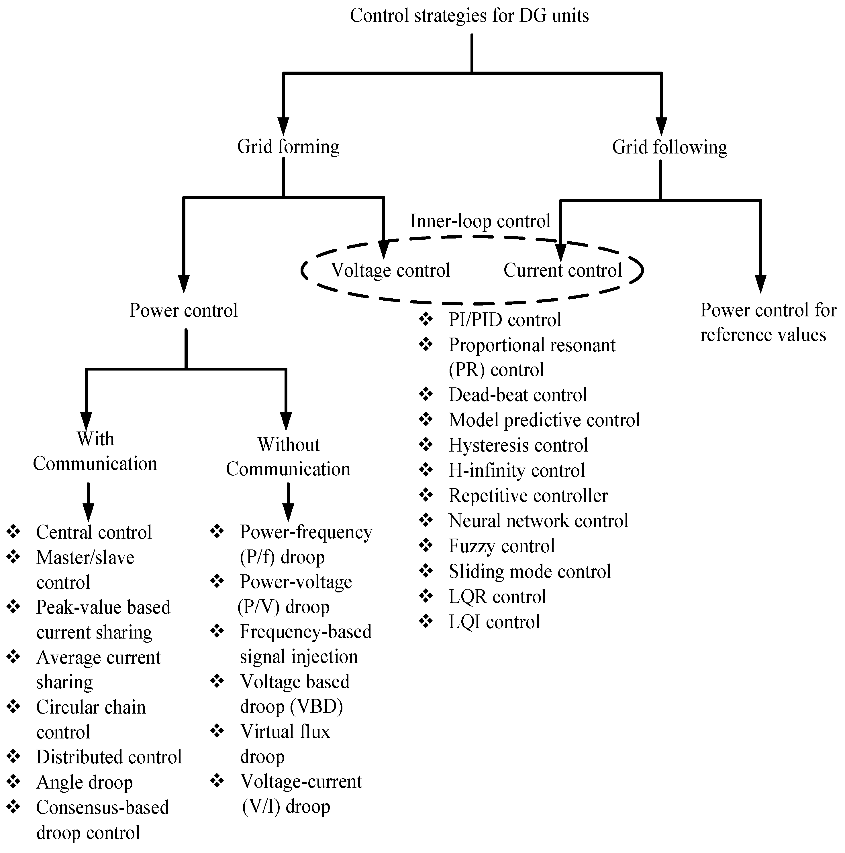
5. Control Strategies in Different Reference Frames

In standalone microgrids, generally, a VSI is used in a voltage controlled operation to regulate the injected voltage and frequency into the network [35,36]. This topology allows inverters to be operated with a precise instantaneous voltage control, an overload rejection, a peak current protection, and adequate dynamics [37]. As the voltage control loop regulates the output inverter voltage and frequency, voltage quality can be improved by a proper design of the voltage controller. The different control approaches can be applied to various reference frames [38].
A transformation of the controlled parameters is, sometimes, essential to improving a controller performance. Therefore, the voltage controller as an inner-loop control of a VSI uses different reference frames, such as a synchronous reference frame ( d q ), stationary reference frame ( α β ) and natural reference frame (abc). Typically, the features of the proposed microgrids determine the required transformation frame. The relationship among different reference frames are depicted in Figure 6.

5.1. Synchronous Rotating Reference Frame

In a synchronous rotating reference frame, also known as a d q transformation or Park transformation, electrical quantities are transferred to dc components by rotating electrical quantities synchronously with the network frequency. Since the outcomes of the frame transformation are dc, controlling and/or filtering of these values are easier by employing a simple PI controller. The real and reactive power can be regulated by accurate calculation of I d * and I q * .

5.2. Stationary Reference Frame

In this control method, the electrical quantities are transformed into a α β transformation frame, which is also known as a Clarke transformation. The transformed quantities are sinusoidal. For this reason, the harmonic rejection and fundamental frequency control through correct gain selections of a simple PI controller are difficult [39]. Therefore, a proportional-resonant (PR) controller is preferred with this transformation. The active and reactive power controls depend on reference currents, I α * and I β * . This method can only be applied in a three-phase system that is similar to the d q reference frame.

5.3. Natural Transformation Frame

In a natural frame control, each phase of the three-phase system is controlled by an individual controller. The control strategy of the natural frame (abc) is divided into linear and non-linear controls [39]. Linear controllers (such as PI and PR) and non-linear controllers (such as hysteresis and deadbeat, both of which have good dynamic behaviour) can be employed in the abc frame [40]. This approach allows for control of both the three-phase and single-phase system without any control parameter transformation.

6. Control Methods for Inner-Loop Control

Numerous control methods, as shown in Figure 7, are developed to improve the power quality, disturbance rejection and voltage/current tracking of the inverter output. The different developed control strategies are used according to the characteristics of microgrids. The control strategies are developed from simple approaches to complex analytical methods. The control methods are described below.

6.1. Proportional-Integral Controller

In a synchronous reference frame transformation, a proportional-integral (PI) controller is often used by implementing its transfer function [41] as follows:
C P I ( s ) = K p + K i s
where K p and K i are the proportional and integral gain, respectively.
The effectiveness of the PI controller can be enhanced by using a feed-forward voltage and/or cross-coupling term. The controller dynamics during voltage fluctuation can be enhanced by the feed-forward voltage [42]. The principal benefit of using the PI controller in the d q frame is that it achieves a zero steady-state error. Therefore, it assists in achieving accurate real and reactive power flows in a network by directly controlling the real and reactive current components.
The PI controller in the d q reference frame is an effective approach for controlling electrical quantities; however, this approach is not suitable in the presence of distorted electrical quantities [43]. Moreover, its implementation in the d q transformation is relatively complex compared to the PR controller in the α β frame, because knowledge of the synchronous frequency and phase are essential.

6.2. Proportional-Resonant Controller

A PR controller can be applied in both the abc and α β reference frames [44,45,46]. The steady-state error of electrical quantities can be easily eliminated by this controller since it has high gain near the resonant frequency [39]. A PR controller can be implemented by:
C P R ( s ) = K p + K i s s 2 + ω 2
where ω is the resonant frequency. The resonant frequency determines the controller performance by maintaining a similar network frequency (i.e., network frequency = resonant frequency), which can be adjusted according to grid frequency variations. The two main drawbacks of this method are accurate tuning needed and sensitivity of the frequency variations.

6.3. Deadbeat Controller

The effective dynamic performance of the deadbeat (DB) predictive controller facilitates the current control of an inverter. The instantaneous current tracking of the DB becomes attractive due to its high bandwidth [47,48,49]. The derivative of control parameters assists predicting its future control action. This control is well known due to its error compensation. The main difficulty of the controller is its sensitivity to the network parameters [50].

6.4. Model Predictive Control

The aim of the developing model predictive control is to minimise the forecast error for accurate current tracking. Managing general constraints and non-linearities of a system with multiple input and output in a flexible control scheme are attractive features of the model predictive control [51]. This strategy uses control actions of the present states to predict the future action of the controlled variables. According to the cost function employed as a criterion, the controller selects the optimal switching states. The mathematical based strategy of the method reveals its sensitivity to parameter variations [52].

6.5. Hysteresis Controller

The hysteresis control approach, being very simple and fast response, produces each leg switching signal for an inverter. The hysteresis controller produces a signal if the error between the reference signal and measured signal exceeds certain limits [53,54]. The advantages of the controller are very simple, easy implementation in practice, and high dynamic responses. It also has an inherent current protection. The challenge of the control approach is to control ripple in the output current hence reducing total harmonic distortion (THD), which may not be acceptable. Moreover, the switching frequency of an inverter varies according to ac voltage and load changes. The design of the output filter is quite difficult owing to randomness of the output.

6.6. H-Infinity Controller

The H method achieves a robust performance in both parameter value changes and worse-case disturbances. Reducing a disturbance effect on output is the prime responsibility of the H controller. In this method, first, the problems are expressed in an optimisation process, then a controller is applied to solve the problems [55]. The specifications of design (robustness and/or tracking performance) are formulated as constraints on singular values of different loop transfer functions. The proper selection of weighting functions allows shaping these loops [56]. The method has numerous advantages, including: robust behaviour in the presence of unbalanced loads, less THD, reduced tracking error and easy implementation in practice. The requirement of perfect mathematical understanding and relatively slow dynamics are the disadvantages of this controller.

6.7. Repetitive Controller

The repetitive control (RC) algorithm (a simple learning control) eliminates error in a dynamic system by using an internal model principle [57,58]. The internal model on an error term gives a series of pole-pairs at multiples of a selected frequency. The parallel combinations of an integral controller, resonant controllers, and a proportional control are considered as a mathematical equivalent of the RC. A low pass filter is employed within the RC to attenuate high-frequency resonant peaks of the controller gains. Therefore, the RC offers a very low harmonic distortion in the output voltage/current, even in the presence of large non-linear loads [59].

6.8. Neural Network

The neural network (NN) allows information to be processed in a systematic way that mimics the function of a biological nerve system with incorporating a time delay. The NN is an architecture—consisting of input layers, hidden layers, and output layers—that is interconnected and operated in parallel mode to transmit signals to one another for achieving a certain processing task [60]. The self-learning feature of the NN algorithm gives feasibility and easy design for different operating conditions and grid disturbances, and augmenting a robust control performance [61].

6.9. Fuzzy Controller

Fuzzy logic is a form of numerous logic values and deals with reality. It deals with linguistic values rather than crisp values, where it ranges 1 for completely true and 0 for completely false [62,63]. In fuzzy control, the concept of fuzzy set membership is used in fuzzy set theory, and the concept of subjective probability is used in probability theory. To minimise overshoot and enhance tracking performance, a fuzzy logic controller is proposed in [64,65].

6.10. Sliding Mode Control

A sliding mode controller (SMC) facilitates a robust performance in the variation of system parameters over wide ranges of the operating points [66]. If a plant deviates from its normal operating points, the controller responds with a strong control action [67]. The controller suffers from chattering problems. Therefore, the SMC parameters are optimised based on output ripple waves to overcome this issue; and an extra integral term of the grid current is added to the sliding surface to eliminate tracking errors. The disturbance rejection, easy implementation, and low sensitivity to the parameter value changes are the key advantages of the SMC method [68].

6.11. Linear Quadratic Regulator

The state feedback of pole placement has advantages: a high degree of freedom and simplicity in implementation. The linear quadratic regulator (LQR) algorithm shows effective performance in both the steady-state and transient conditions [69,70,71]. The method is inherently stable and can be employed independently of the system order [72]. The disadvantage of this method is its tracking accuracy during load changes.

6.12. Linear Quadratic Integrator

The linear quadratic integrator (LQI), minimizing the cost function of the system, is presented in [4] to satisfy the fast dynamic response and nullify the steady-state voltage error between grid voltage and reference grid voltage during load changes. The integral term of controller minimises an error, produced from outside disturbances, in instantaneous reference voltage tracking. This approach is simple to find the optimal gains that provide an acceptable tracking with zero steady-state error.
In summary, the application of the inner-loop control techniques depends on the characteristics of microgrids. For example, if microgrid parameters are sensitive and have high uncertainty, robust controllers are preferable to achieve effective performance. The relative advantages and disadvantages are summarised in Table 1. From the table, it can be concluded that only one controller can not solve all the drawbacks. However, further investigation can improve the design and implementation of these controllers for microgrid application.

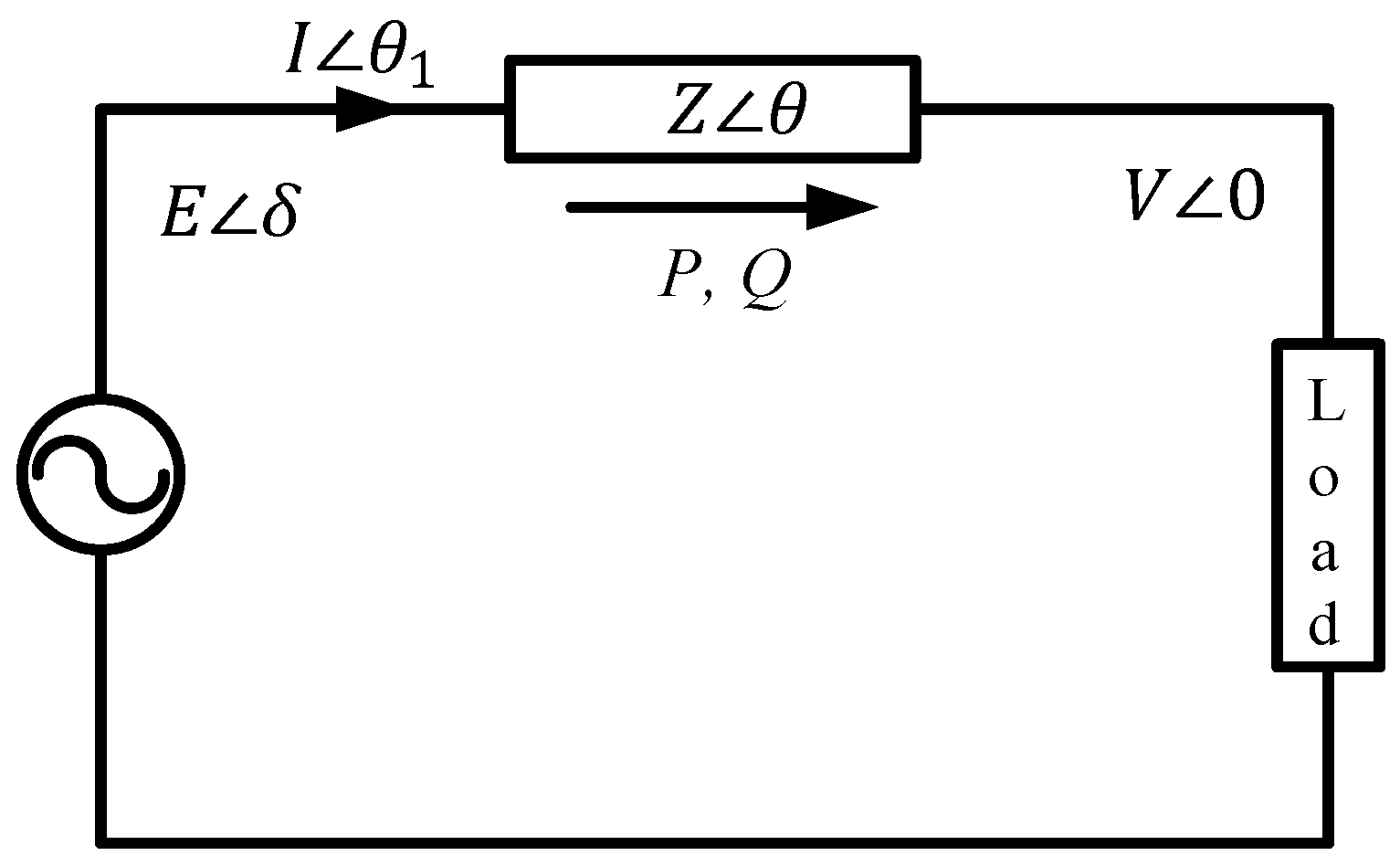
7. Control Methods for Power Sharing

7.1. Communication-Based Control

The communication-based power control achieves good power sharing and voltage regulation. However, expensive communication lines between modules decrease microgrid reliability and limit the DG expansion and flexibility.
The instantaneous reference grid voltage ( v g * ) of a voltage controller shown in Figure 5 is determined by primary controls/power sharing controls, including: centralised control, master-slave control, average load sharing control, peak value based current sharing, circular chain control, distributed control, angle droop control, and consensus-based droop control. A centralised control distributes overall load current evenly among sources through equal current set points for all DG units [73]. In the master-slave control, the master converter works as a VSI by producing controlled voltage, while slave inverters act as CSIs by obeying the current pattern ordered from the master inverter [74,75]. The average load sharing control continuously updates the current reference for each inverter as a weighted average current [76,77]. To achieve proper power sharing and smooth mode transfer, peak-value based current sharing control is applied, where the reference current magnitude of a VSI is determined by the current magnitude of the VSI through peak value calculation [78,79]. In a circular chain control, inverters are assumed to be connected as chain links, and reference currents of inverters are determined by the previous inverter [80]. The distributed control, implemented separately between the low-bandwidth central controller and high-bandwidth local controllers, emphasises the reduction of communication lines to enhance reliability and easy implementation [81]. In angle droop control, a similar method of the P/f droop control as discussed in Section 7.2.1, phase angle is used to control the active power; however, a communication line is required to determine the phase angle reference [82,83]. To reduce dependence on output line impedance and avoid inappropriate reactive power sharing under distributed line impedances, the consensus-based droop control with sparse communication network is presented in [84].

7.2. Communication-Less Control

In the primary control level, the control approaches of DG units are expected without communication to maintain high reliability, reduce costs, avoid communication complexity, and apply plug and play features of each unit. The communication-based operations are unsuitable, especially, if DG units are placed in remote areas because of high bandwidth communication and infrastructure, which is very costly. In this case, droop based control approaches can be applied, and are able to handle different ratings of DG units with great flexibility and reliability. However, this has some drawbacks, such as power (P-Q) control coupling, voltage and frequency deviation, dependence on network impedance, and issues with non-linear loads and accuracy [85,86,87,88]. To overcome these problems, different control approaches are proposed in the literature with their relative advantages and disadvantages [6,7,89].

7.2.1. Power/Frequency Droop Control

In the conventional power system, the power/frequency (P/f) droop control strategy is generally employed to achieve plug and play features. In a large synchronous machine, if power demand increases suddenly, rotation speed of generator drops in order to supply extra power leading to lower frequency of its terminal voltage. As frequency is a global variable and has direct attachment to the rotating speed, each generator of the network increases its mechanical input power to share accurate power.
The application of the P/f droop control in DG units is introduced as a standalone microgrid control [90,91,92]. The P/f droop control of a large synchronous machine is operated based on the synchronous speed which has inertia, but converter-based microgrids lack this inertia. Therefore, the P/f droop control is applied according to the characteristics of power transmission lines. The power flows through the transmission lines can be determined based on the following algorithms.
The current flowing through the impedance, shown in Figure 8, is:
I θ 1 = E δ V 0 Z θ
where E is the supply voltage, V is the terminal voltage, and δ is the power angle or phase difference between the supply voltage and terminal voltage.
The real and reactive power can be written as:
P = ( E V Z cos δ V 2 Z ) cos θ + E V Z sin δ s i n θ
Q = ( E V Z cos δ V 2 Z ) sin θ E V Z sin δ cos θ .
For an inductive transmission line, θ = 90 , Equations (4) and (5) can be written as:
P = E V Z sin δ ; Q = E V Z cos δ V 2 Z .
If δ is small
P E V Z δ ; Q V Z ( E V ) .
From Equation (7), it is concluded that, in an inductive transmission line, the active power has linkage with the phase angle, and the reactive power is associated with the terminal voltage. In the control application, frequency is chosen to regulate the active power instead of phase angle; because DG units do not know the initial phase values of other DG units, and the power angle dynamically depends on the frequency.
In the P/f droop control, the frequency measurement of a converter-based microgrid is not straightforward while the active power measurement is easier [93]. Consequently, a droop in the frequency as a function of the active power is proposed in [94] as:
ω i = ω * K f ( P i P i * ) , i = 1 , 2 , 3 . .
where ω is the angular velocity ( ω = 2 π f ), P i * and P i are the ith reference and measured active power, respectively, and K f is the frequency droop coefficient. This droop coefficient is synthesised according to its capacity to supply proportional power.
The droop gain, K f , can be calculated as follows:
K f = ω * ω m i n P i * P i , m a x > 0
where ω m i n and P i , m a x are the minimum allowable angular frequency and maximum active power, respectively.
Similarly, the voltage amplitude can be measured in accordance with the reactive power measurement as:
V i = V * K v ( Q i Q i * )
where V i is the terminal voltage, Q i * and Q i are ith the reference and measured reactive power, respectively, and K v is the voltage droop gain. The selection of K v and K f have an influence on system stability [95,96].
The droop gain, K v , can be calculated as follows:
K v = V * V m i n Q i * Q i , m a x > 0
where V m i n and Q i , m a x are the minimum allowable voltage and maximum reactive power, respectively.
In the conventional droop control, the voltage control performance and transient responses of this method are lower, and harmonic current cannot be shared appropriately. It has another inherent drawback between the voltage regulation and power sharing [28,97]. In determining the droop coefficient, there is also a trade-off between system stability and droop magnitude. For example, a low droop coefficient slows down the control action, whereas a large coefficient speeds up the load sharing but can lead to instability.
To enhance the system dynamics and avoid a large start up transient, a derivative term is added with an adaptive gain [61] as follows:
ω i = ω * K f P i K ^ f d d P i d t
V i = V * K v Q i K ^ v d d Q i d t
where K ^ f d and K ^ v d are the adaptive transient droop gains. These gains assist in incorporating damping, avoiding large transient and circulating currents.
When the resistive and inductive line impedances of a distribution network are almost similar, i.e., R/X ratio is near unity, a strong bond exists in between active and reactive power called power coupling which leads difficulty in their individual controls. Therefore, to reduce the impact of this coupling, in [98], the droop control method is modified as follows:
ω i = ω * K f ( P i Q i )
V i = V * K v ( P i + Q i ) .
Moreover, the coupling issue of the droop control strategy can be minimised by adding a virtual inductor in the output of the droop control method [99,100,101]. The reference voltage of the voltage control loop becomes [102]:
v * = v fm droop * L v i r d i g d t .
The derivative term in Equation (16) may introduce high-frequency noise, especially during transient conditions which may lead to instability in voltage control [102]. Therefore, to avoid high-frequency noise, a high pass filter can be used instead of pure derivative [103] as follows:
v * = v fm droop * s s + ω c L v i r i g .
Incorporating a virtual impedance in a control loop can successfully impede P-Q coupling, although reactive power sharing error increases. A frame transformation is proposed to prevent P-Q coupling in [104,105].
To share reactive power properly, in [106], additional two terms of which one is used for compensating voltage droop across the transmission lines and another is responsible for improving reactive power sharing with system stability are added to conventional (Q/V) droop control method as follows:
V i = V i * ( K v i + K q i Q i 2 + K p i P i 2 ) Q i + K r i r i P i V i * + K x i x i Q i V i *
where K v i , K q i and K p i are droop coefficients, r i and x i are resistive and inductive line parameters, respectively, K r i and K x i are coefficient ranging in span [0 1]. The parameters ( K q i , K p i , K r i and K x i ) are determined by solving an optimisation problem. Although this method improves reactive power sharing, small error from power line parameters may lead to system instability.
Furthermore, a slow integration term is added in [107] to the conventional Q/V droop control to minimise reactive power sharing errors in which the error is determined by injecting a real-reactive power transient coupling term that is triggered from the central controller using low-bandwidth synchronisation signals. The modified control is shown as follows:
ω i = ω * K f P i K v Q i
V i = V * K v Q i + K c s ( P i P avg )
where K c is an integral term that is kept similar value for all DG units and P avg the steady-state averaged real power. Although the term K v Q in (19) used as offset indicates the power coupling, the integral term used in (20) can bring the accurate real power sharing during any reactive power errors. However, the involvement of central controller for synchronising signal can spoil the whole stability.

7.2.2. Power/Voltage Droop Control

The P/f droop control is well-suited for high-voltage (HV) transmission lines. However, low-voltage (LV) distribution networks have different characteristics from HV networks. LV networks are mainly resistive in nature, leading the active power is linked to the voltage and the reactive power is linked to the frequency [108]. Typical line characteristics are depicted in Table 2 [109]. The principal benefit of the power/voltage (P/V) droop control is that it perfectly matches with the network characteristics. Moreover, the problem of reactive power sharing is solved in this method as frequency is a global parameter, which is used in controlling reactive power. This strategy is especially true if DG units are connected to a microgrid without inductors or transformers, where the output inductance is negligible compared to the resistive impedance values.
For a resistive impedance, θ = 0 , Equations (4) and (5) can be written as follows:
P = V Z ( E cos δ V ) ; Q = E V Z sin δ .
If δ is small
P V Z ( E V ) ; Q E V Z δ .
From Equation (22), the active power depends on voltage difference and its own voltage, while the reactive power relies on the phase angle. The relationship indicates effectiveness of the P/V and Q/f droop control strategies [15,93,110]. From the measured active and reactive powers, rms voltage and frequency can be computed as follows:
V i = V * K v ( P i P i * )
ω i = ω * + K f ( Q i Q i * )
where K v and K f are droop gains.
A comparative study regarding the P/V and P/f droop control in an LV network is investigated in [111], and it is concluded that the P/V shows better-damped response compared to the P/f droop control.
A derivative term is added to the P/V droop control to enhance system dynamics as follows [99]:
V i = V * K v P i K p , d d P i d t
ω i = ω * + K f Q i + K q , d d Q i d t .
A resistive virtual impedance is included for the P-Q decoupling and improving dynamics and stability in [99,112] as follows:
v * = v fm droop * i g R v
where R v is the virtual resistance, and i g is the grid current.
Inverters equipping droop control strategy can be operated with different power set-points during islanded or grid-connected modes of a microgrid due to a difference in power generation capacity and power consumption. Network contingencies (faults on a heavy load side or unintentional islanding) in this situation may lead to inter-unit circulating power caused by a large mismatch in power consumption and power generation, and may change the dc-link voltage beyond its limit. As a result, the protection systems may shut down the inverter because of voltage violation, which may reduce the overall reliability of a microgrid [15,31].

7.2.3. Signal-Injection Based Method

Numerous current sharing strategies depending on frequency coding of the current information are discussed in [113,114]. For power sharing, power lines are utilised as a communication line. In this method, spare control interconnections are not necessary. Frequency signal is calculated by the reactive power droop as:
f q = f q o + K q Q
where f q o is the reference frequency of the injected ac signal, and K q is a boost coefficient. The output voltage, V, can be calculated from the real power droop as follows:
V = V * K p p q .
Harmonic distraction, D, produces by non-linear loads can be shared in the same way. The power of the control signal adjusts the voltage loop bandwidth as follows:
f d = f d o m D
D = S 2 P 2 Q 2
B W = B W o K b d p d
where B W o and K b d are the reference voltage loop bandwidth and the droop coefficient, respectively.
This method accurately regulates the reactive power sharing and is not affected by the line impedance variation [113]. However, it cannot properly guarantee the voltage control. Complexity, high-frequency generation and measurements are the disadvantages of this method. It can reduce power quality. Furthermore, an injected signal can lead to resonance and harmonics. Therefore, harmonic virtual impedance is proposed in [101].

7.2.4. Voltage-Based Droop Control

In the voltage-based droop control, the characteristics of renewable energy sources are considered in power sharing strategies of a microgrid [115]. This method divides the P/V droop control into two droop controls, namely P d c / V g and V g / V d c droop control, and a constant power-band is added to the P d c / V g droop control.
The V g / V d c droop control is responsible for indicating power supply status, for example, extra generated power causes high dc-link voltage and lower generated power leads to low dc-link voltage. The V g / V d c droop control is expressed as follows:
V g * = V g + K v ( V d c V d c )
where V g and V d c are the set/reference terminal voltage and the dc-link voltage, respectively. In this method, variation in terminal voltage also alters power supply to the network. To limit a voltage deviation up to a certain point, the P d c / V g droop control is applied, as:
P d c = P d c K p { V g ( 1 + b ) V g } if V g > ( 1 + b ) V g P d c K p { V g ( 1 b ) V g } if V g < ( 1 b ) V g P d c if ( 1 b ) V g V g ( 1 + b ) V g
where P d c is the set active dc power supply, b is the constant power band, and K p is the power droop coefficient. Constant power-bands are responsible for sharing power into the network among dispatchable and non-dispatchable sources, where the V g / V d c controller facilitates the dc-link voltage control.
This method takes full advantage of acceptable voltage deviation by incorporating a power band in P d c / V g control strategy. For this reason, renewable energy sources can be utilised effectively with maximum power point tracking. In addition, this method can supply flexible power without violating the voltage limit to the network if voltage deviation goes beyond the constant power band. However, in this control approach, the stability margin of the method and its practical implementation were not yet investigated. Moreover, active power control in [115] is postponed up to a certain limit of the terminal voltage considering the features of renewable energy sources (RESs). But, recent RESs use an energy storage element [116], such as a battery that can deliver power into the network during power mismanagement like a dispatchable generator. Therefore, the method (VBD) needs to be modified for application in microgrids.

7.2.5. Virtual Flux Droop Control

To simplify an inverter control by eliminating multi-feedback loops and PWM, the virtual flux method is first introduced in [91] as parallel connected inverter control and latter it is presented as a microgrid control in [117]. The working principle of the virtual flux droop control is to droop the virtual flux instead of inverter voltage droop. This method is applied in power sharing approach to improve frequency deviation compared to the conventional one. The reason of improving frequency regulation is that angular frequency of a virtual flux vector does not depend on angular differences. In this method, active and reactive powers are proportional to the flux phase angle difference and flux magnitude difference as follows:
δ = δ * m ( P rated P )
| Φ v | = | Φ v * | n ( Q rated Q )
where δ * and Φ v * are the reference phase angle difference of two flux amplitudes and reference inverter output flux amplitude, respectively; P rated and Q rated are active and reactive power ratings of DG units, respectively; m and n are the coefficients of P δ and Q | Φ v | droop control.

7.2.6. V/I Droop Characteristic Method

A control method based on voltage/current (V/I) characteristics is proposed in [118] to improve reactive power sharing, dynamic and stability of microgrids by drooping the direct and quadrature axis voltage components with the corresponding currents according to a piecewise linear droop function. In the V/I droop control, the inverter output voltage is drooped with respect to inverter output current. In this method, two voltage signals are added to the d and q reference voltage and the injected voltage are droop signals of steady-state and transient components. The V/I droop can be represented as follows:
V q i * = V o + R i i q i + X i i d i m i f ( i q i )
V d i * = R i i d i X i i q i n i f ( i d i )
where the droop coefficients (m and n) are selected inversely proportional to the DG rating and f ( i d q ) are arbitrary functions of the currents and line impedances. This method may suffer from unbalanced load currents on controller performances and oscillation issue for small droop coefficient [119], and needs further investigation for exploring its application on non-dispatchable DG units.

7.2.7. Other Control Methods

A multi-variable droop synchronous current converter control method is described in [120] to manage currents of an LV network by enabling decouple of d- and q-axis current using the loop shaping technique. To improve power sharing performance and line impedance mismatches, extra loops, such as reactive current loop and on-line reactive power offset estimator, are incorporated in [102,121]. A Q / V ˙ droop control technique with designing V ˙ , rate of change of voltage magnitude, restoration mechanism is presented in [122] to enhance reactive power sharing and maintain steady-state voltage magnitude.

8. Future Work

From the above literature review, it is clear that each and every control technique has its own unique application, benefits and drawbacks as shown in Table 1 and Table 3. It is important to take into consideration the high penetration of the RESs with different power ratings in a distribution network. This makes complexity in controlling microgrids, especially in network power quality and accurate power sharing techniques among DG units. Therefore, advanced control techniques (such as artificial intelligent, predictive control and multi-agent systems) need to be designed/implemented to maintain power quality and improve the power sharing issues. As the effective control application depends on model accuracy of the system, the uncertainty model of a microgrid, for example catastrophe, power and load uncertainty, should also be considered while designing a controller. Furthermore, the complexity of the advanced algorithms can be further reduced to implement it in practical systems.
Most of the DG units in a microgrid are based on renewable energy sources, which have a low-inertia compared to conventional generators. These low-inertia of DG units may experience severe voltage and/or frequency changes during abrupt disturbances. Although some of the research work is presented to increase the response time of the DG units by applying flywheel and/or mimicking synchronous generators [123,124,125,126,127,128,129], there are still opportunities for researchers to further examine the microgrid with improved inertia.
Application of different types of loads in a microgrid has an adverse effect on a DG unit control and operation. However, research work is frequently validated by the simulation of the above controllers with linear loads for power quality improvements and power sharing techniques. There are opportunities to validate the controllers with non-linear loads, such as dynamic loads, electric vehicles, constant power loads, and induction motors, which are seldom applied in literature. The application of these types of loads with experimental setup needs to be reconsidered in the future research.
Maintaining stable operation of microgrids becomes challenging due to the increased participation of non-linear loads and high penetration of DG units. Although the microgrid stabilities with linear loads are extensively studied over the past period [95,130,131,132], the determination of stability margins for DG units and synchronous generators with non-linear loads, such as induction motors, constant power loads and electrical vehicles are not studied thoroughly.

9. Conclusions

This paper presents a technical overview of different control techniques for DG units in an islanded microgrid. The aim of this research is to provide a detailed and thorough review of different control levels of microgrids which is very important in the development of smart microgrids. The historical development of the control methods used in the power industry and those reported in the literature is documented. The key discussions are divided into two parts: inner-loop controls and primary controls without communication. It is realised from the literature review on inner-loop controllers that the acceptability of suitable inner-loop controls for DG units completely depends on the microgrid characteristics. For example, if microgrid parameters are sensitive, robust controllers for voltage control are preferable. In addition, if the harmonics are in a concern, certain controllers are able to address this, e.g., resonant and predictive controllers, compared with others like PI controller. On the other hand, as a primary control, communication-based controls suffer from risk of communication failure that can jeopardise microgrid stability, whereas droop based controls have exhibited a superior performance in terms of power sharing, power quality, reliability, flexibility, and extensibility. The shortcomings of conventional power sharing are overcome by applying various techniques, such as virtual impedances, frame transformation, V/I droop control and so on. Each method has its unique features. Different control approaches are compared in this paper showing their relative benefits and drawbacks. Moreover, the future research direction that needs to be carried out for the development and implementation of smart microgrids is also presented.

Author Contributions

Md Alamgir Hossain has written the manuscript under the supervision of Hemanshu Roy Pota. Walid Issa and Md Jahangir Hossain have supported the manuscript in terms of scientific and technical expertise, and improving the paper quality. All authors contributed to bringing the manuscript in its current state.

Conflicts of Interest

The authors declare no conflict of interest.

Abbreviations

The following abbreviations are used in this manuscript:
DGsDistributed generations
RESsRenewable energy sources
PECsPower electronic converters
MOSFETsMetal-oxide-semiconductor field-effect transistors
PWMPulse width modulation
CSIsCurrent source inverters
VSIsVoltage source inverters
PCCPoint of common coupling
SCSupervisory controller
MGCCMicrogrid central control
PLLPhase-locked loop
PRProportional-resonant
DBDeadbeat
THDTotal harmonic distortion
SMCSliding mode control
LQRLinear quadratic regulator
LQILinear quadratic integrator
VBDVoltage-based droop
RCRepetitive controller
NNNeural network
m i Modulation index of PWM
GGenerator
ZLine impedance
ESupply voltage
VTerminal voltage
SApparent power
PActive power
QReactive power
LFilter inductor
CFilter capacitor
C d c DC-link capacitor
v g Instantaneous grid voltage
v g * Reference instantaneous voltage for control
i L Instantaneous line current
i L * Reference instantaneous current for control
V * Reference grid voltage
ω * Reference angular frequency
P m Measured active power
Q m Measured reactive power
P * Reference active power
Q * Reference reactive power
I d Direct axis current component
I q Quadratic axis current component
I d * Reference direct current component
I q * Reference quadratic current component
I α Alpha axis current component
I β Beta axis current component
ω s * Reference angular frequency set by supervisory controller
V s * Reference voltage set by supervisory controller
p q Small real power in the injected signal

References

  1. Jin, M.; Feng, W.; Liu, P.; Marnay, C.; Spanos, C. MOD-DR: Microgrid optimal dispatch with demand response. Appl. Energy 2017, 187, 758–776. [Google Scholar] [CrossRef]
  2. Hossain, M.A.; Ahmed, M.R. Present energy scenario and potentiality of wind energy in Bangladesh. World Acad. Sci. Eng. Technol. 2013, 7, 1001–1005. [Google Scholar]
  3. Jin, M.; Feng, W.; Marnay, C.; Spanos, C. Microgrid to enable optimal distributed energy retail and end-user demand response. Appl. Energy 2017. [Google Scholar] [CrossRef]
  4. Hossain, M.A.; Azim, M.I.; Mahmud, M.A.; Pota, H.R. Primary Voltage Control of a Single-phase Inverter using Linear Quadratic Regulator with Integrator. In Proceedings of the 2015 Australasian Universities Power Engineering Conference (AUPEC), Wollongong, Australia, 27–30 September 2015. [Google Scholar]
  5. Han, H.; Hou, X.; Yang, J.; Wu, J.; Su, M.; Guerrero, J.M. Review of power sharing control strategies for islanding operation of AC microgrids. IEEE Trans. Smart Grid 2016, 7, 200–215. [Google Scholar] [CrossRef]
  6. Vandoorn, T.; De Kooning, J.; Meersman, B.; Vandevelde, L. Review of primary control strategies for islanded microgrids with power-electronic interfaces. Renew. Sustain. Energy Rev. 2013, 19, 613–628. [Google Scholar] [CrossRef]
  7. Bidram, A.; Davoudi, A. Hierarchical structure of microgrids control system. IEEE Trans. Smart Grid 2012, 3, 1963–1976. [Google Scholar] [CrossRef]
  8. Hossain, M.A.; Azim, M.I.; Mahmud, M.A.; Pota, H.R. Active power control in an islanded microgrid using DC link voltage status. In Proceedings of the 2015 IEEE Innovative Smart Grid Technologies-Asia (ISGT ASIA), Bangkok, Thailand, 3–6 November 2015; pp. 1–6. [Google Scholar]
  9. Chung, H.S.H.; Wang, H.; Blaabjerg, F.; Pecht, M. Reliability of Power Electronic Converter Systems; The Institution of Engineering and Technology: London, UK, 2016. [Google Scholar]
  10. Mohan, N.; Undeland, T.M. Power Electronics: Converters, Applications, and Design; John Wiley & Sons: Hoboken, NJ, USA, 2007. [Google Scholar]
  11. Erickson, R.W.; Maksimovic, D. Fundamentals of Power Electronics; Springer Science & Business Media: New York, NY, USA, 2007. [Google Scholar]
  12. Katiraei, F.; Iravani, R.; Hatziargyriou, N.; Dimeas, A. Microgrids management. IEEE Power Energy Mag. 2008, 6, 54–65. [Google Scholar] [CrossRef]
  13. Lopes, J.; Moreira, C.; Madureira, A. Defining control strategies for microgrids islanded operation. IEEE Trans. Power Syst. 2006, 21, 916–924. [Google Scholar] [CrossRef]
  14. Lasseter, R.H. Microgrids. In Proceedings of the 2002 Power Engineering Society Winter Meeting, New York, NY, USA, 27–31 January 2002; IEEE: Piscataway, NJ, USA, 2002; Volume 1, pp. 305–308. [Google Scholar]
  15. Hossain, M.A.; Pota, H.R.; Haruni, A.M.O.; Hossain, M.J. DC-link voltage regulation of inverters to enhance microgrid stability during network contingencies. Electr. Power Syst. Res. 2017, 147, 233–244. [Google Scholar] [CrossRef]
  16. Bhaskara, S.N.; Chowdhury, B.H. Microgrids—A review of modeling, control, protection, simulation and future potential. In Proceedings of the 2012 IEEE Power and Energy Society General Meeting, San Diego, CA, USA, 22–26 July 2012; IEEE: Piscataway, NJ, USA, 2012; pp. 1–7. [Google Scholar]
  17. Hatziargyriou, N.; Asano, H.; Iravani, R.; Marnay, C. Microgrids. IEEE Power Energy Mag. 2007, 5, 78–94. [Google Scholar] [CrossRef]
  18. Nejabatkhah, F.; Li, Y.W. Overview of power management strategies of hybrid AC/DC microgrid. IEEE Trans. Power Electron. 2015, 30, 7072–7089. [Google Scholar] [CrossRef]
  19. Green, T.; Prodanovi, M. Control of inverter-based micro-grids. Electr. Power Syst. Res. 2007, 77, 1204–1213. [Google Scholar] [CrossRef]
  20. Prodanovi, M.; Green, T. Power quality improvement in grid connection of three-phase inverters. In Proceedings of the International Conference on Power Electronics, Machines and Drives, 2002 (Conf. Publ. No. 487), Sante Fe, NM, USA, 4–7 June 2002; IET: London, UK, 2002; pp. 24–29. [Google Scholar]
  21. Abeyasekera, T.; Johnson, C.M.; Atkinson, D.J.; Armstrong, M. Suppression of line voltage related distortion in current controlled grid connected inverters. IEEE Trans. Power Electron. 2005, 20, 1393–1401. [Google Scholar] [CrossRef]
  22. Sofla, M.A.; Wang, L.; King, R. Modeling and Control of DC-AC Power Converters of Distributed Energy Resources in Microgrids. In Modeling and Control of Sustainable Power Systems; Springer: Berlin/Heidelberg, Germany, 2012; pp. 341–366. [Google Scholar]
  23. Issa, W.; Abusara, A.; Sharkh, S. Impedance interaction between islanded parallel voltage source inverters and the distribution network. In Proceedings of the 7th IET International Conference on Power Electronics, Machines and Drives (PEMD 2014), Manchester, UK, 8–10 April 2014. [Google Scholar]
  24. Hossain, M.A.; Pota, H.R. Voltage tracking of a single-phase inverter in an islanded microgrid. Int. J. Renew. Energy Res. 2015, 5, 806–814. [Google Scholar]
  25. Kim, J.; Lee, J.; Nam, K. Inverter-based local AC bus voltage control utilizing two DOF control. IEEE Trans. Power Electron. 2008, 23, 1288–1298. [Google Scholar]
  26. Vandoorn, T.L.; Meersman, B.; De Kooning, J.D.; Vandevelde, L. Analogy between conventional grid control and islanded microgrid control based on a global DC-link voltage droop. IEEE Trans. Power Deliv. 2012, 27, 1405–1414. [Google Scholar] [CrossRef] [Green Version]
  27. Piagi, P.; Lasseter, R.H. Industrial Application of MicroGrids; Power System Engineering Research Center, University of Wisconsin-Madison: Madison, WI, USA, 2001. [Google Scholar]
  28. Guerrero, J.M.; Vasquez, J.C.; Matas, J.; Vicuna, D.; García, L.; Castilla, M. Hierarchical control of droop-controlled AC and DC microgrids—A general approach toward standardization. IEEE Trans. Ind. Electron. 2011, 58, 158–172. [Google Scholar]
  29. Mehrizi-Sani, A.; Iravani, R. Potential-function based control of a microgrid in islanded and grid-connected modes. IEEE Trans. Power Syst. 2010, 25, 1883–1891. [Google Scholar] [CrossRef]
  30. Karimi, H.; Nikkhajoei, H.; Iravani, R. Control of an electronically-coupled distributed resource unit subsequent to an islanding event. IEEE Trans. Power Deliv. 2008, 23, 493–501. [Google Scholar] [CrossRef]
  31. Issa, W.R.; Abusara, M.A.; Sharkh, S.M. Control of transient power during unintentional islanding of microgrids. IEEE Trans. Power Electron. 2015, 30, 4573–4584. [Google Scholar] [CrossRef]
  32. Lu, X.; Guerrero, J.M.; Sun, K.; Vasquez, J.C.; Teodorescu, R.; Huang, L. Hierarchical control of parallel AC-DC converter interfaces for hybrid microgrids. IEEE Trans. Smart Grid 2014, 5, 683–692. [Google Scholar] [CrossRef]
  33. Guerrero, J.M.; Chandorkar, M.; Lee, T.L.; Loh, P.C. Advanced control architectures for intelligent microgrids, part I: Decentralized and hierarchical control. IEEE Trans. Ind. Electron. 2013, 60, 1254–1262. [Google Scholar] [CrossRef]
  34. Savaghebi, M.; Jalilian, A.; Vasquez, J.C.; Guerrero, J.M. Secondary control for voltage quality enhancement in microgrids. IEEE Trans. Smart Grid 2012, 3, 1893–1902. [Google Scholar] [CrossRef]
  35. Ko, S.H.; Lee, S.R.; Dehbonei, H.; Nayar, C.V. Application of voltage-and current-controlled voltage source inverters for distributed generation systems. IEEE Trans. Energy Convers. 2006, 21, 782–792. [Google Scholar] [CrossRef]
  36. Li, Y.W. Control and resonance damping of voltage-source and current-source converters with filters. IEEE Trans. Ind. Electron. 2009, 56, 1511–1521. [Google Scholar]
  37. Irwin, J.; Kazmierkowski, M.P.; Krishnan, R.; Blaabjerg, F. Control in Power Electronics: Selected Problems; Academic Press: New York, NY, USA, 2002. [Google Scholar]
  38. Rocabert, J.; Luna, A.; Blaabjerg, F.; Rodrguez, P. Control of power converters in AC microgrids. IEEE Trans. Power Electron. 2012, 27, 4734–4749. [Google Scholar] [CrossRef]
  39. Blaabjerg, F.; Teodorescu, R.; Liserre, M.; Timbus, A.V. Overview of control and grid synchronization for distributed power generation systems. IEEE Trans. Ind. Electron. 2006, 53, 1398–1409. [Google Scholar] [CrossRef]
  40. Timbus, A.V.; Teodorescu, R.; Blaabjerg, F.; Liserre, M.; Rodriguez, P. Linear and nonlinear control of distributed power generation systems. In Proceedings of the Conference Record of the 2006 IEEE Industry Applications Conference 41st IAS Annual Meeting, Tampa, FL, USA, 8–12 October 2006; IEEE: Piscataway, NJ, USA, 2006; Volume 2, pp. 1015–1023. [Google Scholar]
  41. Vandoorn, T.; Renders, B.; De Belie, F.; Meersman, B.; Vandevelde, L. A voltage-source inverter for microgrid applications with an inner current control loop and an outer voltage control loop. In Proceedings of the International Conference on Renewable Energies and Power Quality (ICREPQ ’09), Valencia, Spain, 15–17 April 2009. [Google Scholar]
  42. Abusara, M.A.; Sharkh, S.M.; Guerrero, J.M. Improved droop control strategy for grid-connected inverters. Sustain. Energy Grids Netw. 2015, 1, 10–19. [Google Scholar] [CrossRef]
  43. Weiss, G.; Zhong, Q.C.; Green, T.C.; Liang, J. H-infinity repetitive control of DC-AC converters in microgrids. IEEE Trans. Power Electron. 2004, 19, 219–230. [Google Scholar] [CrossRef]
  44. Teodorescu, R.; Blaabjerg, F.; Liserre, M.; Loh, P.C. Proportional-resonant controllers and filters for grid-connected voltage-source converters. IEE Proc. Electr. Power Appl. 2006, 153, 750–762. [Google Scholar] [CrossRef]
  45. Yan, Y.; Wang, M.; Song, Z.F.; Xia, C.L. Proportional-resonant control of doubly-fed induction generator wind turbines for low-voltage ride-through enhancement. Energies 2012, 5, 4758–4778. [Google Scholar] [CrossRef]
  46. Vidal, A.; Freijedo, F.D.; Yepes, A.; Fernandez-Comesana, P.; Malvar, J.; Lopez, O.; Doval-Gandoy, J. Assessment and optimization of the transient response of proportional-resonant current controllers for distributed power generation systems. IEEE Trans. Ind. Electron. 2013, 60, 1367–1383. [Google Scholar] [CrossRef]
  47. Xueguang, Z.; Wenjie, Z.; Jiaming, C.; Dianguo, X. Deadbeat control strategy of circulating currents in parallel connection system of three-phase PWM converter. IEEE Trans. Energy Convers. 2014, 29, 406–417. [Google Scholar]
  48. Kim, J.; Hong, J.; Kim, H. Improved Direct Deadbeat Voltage Control with an Actively Damped Inductor-Capacitor Plant Model in an Islanded AC Microgrid. Energies 2016, 9, 978. [Google Scholar] [CrossRef]
  49. Song, W.; Ma, J.; Zhou, L.; Feng, X. Deadbeat Predictive Power Control of Single-Phase Three-Level Neutral-Point-Clamped Converters Using Space-Vector Modulation for Electric Railway Traction. IEEE Trans. Power Electron. 2016, 31, 721–732. [Google Scholar] [CrossRef]
  50. Timbus, A.; Liserre, M.; Teodorescu, R.; Rodriguez, P.; Blaabjerg, F. Evaluation of current controllers for distributed power generation systems. IEEE Trans. Power Electron. 2009, 24, 654–664. [Google Scholar] [CrossRef]
  51. Hu, J.; Zhu, J.; Dorrell, D.G. Model predictive control of grid-connected inverters for PV systems with flexible power regulation and switching frequency reduction. IEEE Trans. Ind. Appl. 2015, 51, 587–594. [Google Scholar] [CrossRef]
  52. Cortés, P.; Kazmierkowski, M.P.; Kennel, R.M.; Quevedo, D.E.; Rodríguez, J. Predictive control in power electronics and drives. IEEE Trans. Ind. Electron. 2008, 55, 4312–4324. [Google Scholar] [CrossRef]
  53. Rahim, N.A.; Selvaraj, J.; Krismadinata. Implementation of hysteresis current control for single-phase grid connected inverter. In Proceedings of the 2007 7th International Conference on Power Electronics and Drive Systems, Bangkok, Thailand, 27–30 November 2007. [Google Scholar]
  54. Prabhakar, N.; Mishra, M.K. Dynamic hysteresis current control to minimize switching for three-phase four-leg VSI topology to compensate nonlinear load. IEEE Trans. Power Electron. 2010, 25, 1935–1942. [Google Scholar] [CrossRef]
  55. Hornik, T.; Zhong, Q.C. Parallel PI voltage-H current controller for the neutral point of a three-phase inverter. IEEE Trans. Ind. Electron. 2013, 60, 1335–1343. [Google Scholar] [CrossRef]
  56. Zhong, Q.C.; Hornik, T. Cascaded current–voltage control to improve the power quality for a grid-connected inverter with a local load. IEEE Trans. Ind. Electron. 2013, 60, 1344–1355. [Google Scholar] [CrossRef]
  57. Hara, S.; Yamamoto, Y.; Omata, T.; Nakano, M. Repetitive control system: A new type servo system for periodic exogenous signals. IEEE Trans. Autom. Control 1988, 33, 659–668. [Google Scholar] [CrossRef] [Green Version]
  58. Jin, W.; Li, Y.; Sun, G.; Bu, L. H-infinity Repetitive Control Based on Active Damping with Reduced Computation Delay for LCL-Type Grid-Connected Inverters. Energies 2017, 10, 586. [Google Scholar] [CrossRef]
  59. Liu, T.; Wang, D. Parallel Structure Fractional Repetitive Control for PWM Inverters. IEEE Trans. Ind. Electron. 2015, 62, 5045–5054. [Google Scholar] [CrossRef]
  60. Hatti, M.; Tioursi, M. Dynamic neural network controller model of PEM fuel cell system. Int. J. Hydrogen Energy 2009, 34, 5015–5021. [Google Scholar]
  61. Mohamed, Y.A.R.I.; El-Saadany, E.F. Adaptive decentralized droop controller to preserve power sharing stability of paralleled inverters in distributed generation microgrids. IEEE Trans. Power Electron. 2008, 23, 2806–2816. [Google Scholar] [CrossRef]
  62. Suganthi, L.; Iniyan, S.; Samuel, A.A. Applications of fuzzy logic in renewable energy systems—A review. Renew. Sustain. Energy Rev. 2015, 48, 585–607. [Google Scholar] [CrossRef]
  63. Musa, S.; Radzi, M.A.M.; Hizam, H.; Wahab, N.I.A.; Hoon, Y.; Zainuri, M.A.A.M. Modified Synchronous Reference Frame Based Shunt Active Power Filter with Fuzzy Logic Control Pulse Width Modulation Inverter. Energies 2017, 10, 758. [Google Scholar] [CrossRef]
  64. Hasanien, H.M.; Matar, M. A fuzzy logic controller for autonomous operation of a voltage source converter-based distributed generation system. IEEE Trans. Smart Grid 2015, 6, 158–165. [Google Scholar] [CrossRef]
  65. Sefa, I.; Altin, N.; Ozdemir, S.; Kaplan, O. Fuzzy PI controlled inverter for grid interactive renewable energy systems. IET Renew. Power Gener. 2015, 9, 729–738. [Google Scholar] [CrossRef]
  66. Chen, Z.; Luo, A.; Wang, H.; Chen, Y.; Li, M.; Huang, Y. Adaptive sliding-mode voltage control for inverter operating in islanded mode in microgrid. Int. J. Electr. Power Energy Syst. 2015, 66, 133–143. [Google Scholar] [CrossRef]
  67. Hao, X.; Yang, X.; Xie, R.; Huang, L.; Liu, T.; Li, Y. A fixed switching frequency integral resonant sliding mode controller for three-phase grid-connected photovoltaic inverter with LCL-filter. In Proceedings of the 2013 IEEE ECCE Asia Downunder (ECCE Asia), Melbourne, Australia, 3–6 June 2013; IEEE: Piscataway, NJ, USA, 2013; pp. 793–798. [Google Scholar]
  68. Esmaeli, A. Stability analysis and control of microgrids by sliding mode control. Int. J. Electr. Power Energy Syst. 2016, 78, 22–28. [Google Scholar]
  69. Ahmed, K.; Massoud, A.; Finney, S.; Williams, B. Optimum selection of state feedback variables PWM inverters control. In Proceedings of the 4th IET Conference on Power Electronics, Machines and Drives, York, UK, 2–4 April 2008. [Google Scholar]
  70. Lalili, D.; Mellit, A.; Lourci, N.; Medjahed, B.; Boubakir, C. State feedback control of a three level grid-connected photovoltaic inverter. In Proceedings of the 2012 9th International Multi-Conference on Systems, Signals and Devices (SSD), Chemnitz, Germany, 20–23 March 2012; IEEE: Piscataway, NJ, USA, 2012; pp. 1–6. [Google Scholar]
  71. Xue, M.; Zhang, Y.; Kang, Y.; Yi, Y.; Li, S.; Liu, F. Full feedforward of grid voltage for discrete state feedback controlled grid-connected inverter with LCL filter. IEEE Trans. Power Electron. 2012, 27, 4234–4247. [Google Scholar] [CrossRef]
  72. Jaen, C.; Pou, J.; Pindado, R.; Sala, V.; Zaragoza, J. A linear-quadratic regulator with integral action applied to PWM dc-dc converters. In Proceedings of the IECON 2006—32nd Annual Conference on Industrial Electronics, Paris, France, 6–10 November 2006; IEEE: Piscataway, NJ, USA, 2006; pp. 2280–2285. [Google Scholar]
  73. Siri, K.; Lee, C.; Wu, T.F. Current distribution control for parallel connected converters. I. IEEE Trans. Aerosp. Electron. Syst. 1992, 28, 829–840. [Google Scholar] [CrossRef]
  74. Chen, J.F.; Chu, C.L. Combination voltage-controlled and current-controlled PWM inverters for UPS parallel operation. IEEE Trans. Power Electron. 1995, 10, 547–558. [Google Scholar] [CrossRef]
  75. Pei, Y.; Jiang, G.; Yang, X.; Wang, Z. Auto-master-slave control technique of parallel inverters in distributed AC power systems and UPS. In Proceedings of the 2004 IEEE 35th Annual Power Electronics Specialists Conference, Aachen, Germany, 20–25 June 2004; IEEE: Piscataway, NJ, USA, 2004; Volume 3, pp. 2050–2053. [Google Scholar]
  76. Roslan, A.M.; Ahmed, K.H.; Finney, S.J.; Williams, B.W. Improved instantaneous average current-sharing control scheme for parallel-connected inverter considering line impedance impact in microgrid networks. IEEE Trans. Power Electron. 2011, 26, 702–716. [Google Scholar] [CrossRef]
  77. Sun, X.; Lee, Y.S.; Xu, D. Modeling, analysis, and implementation of parallel multi-inverter systems with instantaneous average-current-sharing scheme. IEEE Trans. Power Electron. 2003, 18, 844–856. [Google Scholar]
  78. Chen, C.L.; Wang, Y.; Lai, J.S.; Lee, Y.S.; Martin, D. Design of parallel inverters for smooth mode transfer microgrid applications. IEEE Trans. Power Electron. 2010, 25, 6–15. [Google Scholar] [CrossRef]
  79. Chen, Q.; Ju, P.; Shi, K.; Tang, Y.; Shao, Z.; Yang, W. Parameter estimation and comparison of the load models with considering distribution network directly or indirectly. Int. J. Electr. Power Energy Syst. 2010, 32, 965–968. [Google Scholar] [CrossRef]
  80. Wu, T.F.; Chen, Y.K.; Huang, Y.H. 3C strategy for inverters in parallel operation achieving an equal current distribution. IEEE Trans. Ind. Electron. 2000, 47, 273–281. [Google Scholar]
  81. Prodanović, M.; Green, T.C. High-quality power generation through distributed control of a power park microgrid. IEEE Trans. Ind. Electron. 2006, 53, 1471–1482. [Google Scholar] [CrossRef] [Green Version]
  82. Majumder, R.; Chaudhuri, B.; Ghosh, A.; Majumder, R.; Ledwich, G.; Zare, F. Improvement of stability and load sharing in an autonomous microgrid using supplementary droop control loop. IEEE Trans. Power Syst. 2010, 25, 796–808. [Google Scholar] [CrossRef]
  83. Pota, H.R.; Hossain, M.J.; Mahmud, M.; Gadh, R. Control for microgrids with inverter connected renewable energy resources. In Proceedings of the IEEE PES General Meeting| Conference & Exposition, National Harbor, MD, USA, 27–31 July 2014; pp. 1–5. [Google Scholar]
  84. Lu, L.Y.; Chu, C.C. Consensus-based droop control synthesis for multiple DICs in isolated micro-grids. IEEE Trans. Power Syst. 2015, 30, 2243–2256. [Google Scholar] [CrossRef]
  85. Yu, X.; Khambadkone, A.M.; Wang, H.; Terence, S.T.S. Control of parallel-connected power converters for low-voltage microgrid—Part I: A hybrid control architecture. IEEE Trans. Power Electron. 2010, 25, 2962–2970. [Google Scholar] [CrossRef]
  86. Delghavi, M.B.; Yazdani, A. An adaptive feedforward compensation for stability enhancement in droop-controlled inverter-based microgrids. IEEE Trans. Power Deliv. 2011, 26, 1764–1773. [Google Scholar] [CrossRef]
  87. Xinchun, L.; Feng, F.; Shanxu, D.; Yong, K.; Jian, C. The droop characteristic decoupling control of parallel connected UPS with no control interconnection. In Proceedings of the 2003 IEEE International Electric Machines and Drives Conference, Madison, WI, USA, 1–4 June 2003; IEEE: Piscataway, NJ, USA, 2003; Volume 3, pp. 1777–1780. [Google Scholar]
  88. Olivares, D.E.; Mehrizi-Sani, A.; Etemadi, A.H.; Cañizares, C.A.; Iravani, R.; Kazerani, M.; Hajimiragha, A.H.; Gomis-Bellmunt, O.; Saeedifard, M.; Palma-Behnke, R.; et al. Trends in microgrid control. IEEE Trans. Smart Grid 2014, 5, 1905–1919. [Google Scholar] [CrossRef]
  89. Han, Y.; Li, H.; Shen, P.; Coelho, E.A.A.; Guerrero, J.M. Review of active and reactive power sharing strategies in hierarchical controlled microgrids. IEEE Trans. Power Electron. 2017, 32, 2427–2451. [Google Scholar] [CrossRef]
  90. Barklund, E.; Pogaku, N.; Prodanovic, M.; Hernandez-Aramburo, C.; Green, T.C. Energy management in autonomous microgrid using stability-constrained droop control of inverters. IEEE Trans. Power Electron. 2008, 23, 2346–2352. [Google Scholar] [CrossRef]
  91. Chandorkar, M.C.; Divan, D.M.; Adapa, R. Control of parallel connected inverters in standalone AC supply systems. IEEE Trans. Ind. Appl. 1993, 29, 136–143. [Google Scholar] [CrossRef]
  92. Marwali, M.N.; Jung, J.W.; Keyhani, A. Control of distributed generation systems-Part II: Load sharing control. IEEE Trans. Power Electron. 2004, 19, 1551–1561. [Google Scholar] [CrossRef]
  93. Engler, A.; Osika, O.; Barnes, M.; Hatziargyriou, N. DB2 Evaluation of the Local Controller Strategies; European Commission: Brussels, Belgium; Luxembourg, 2005. [Google Scholar]
  94. Bhuiyan, F.A.; Yazdani, A. Multimode control of a DFIG-based wind-power unit for remote applications. IEEE Trans. Power Deliv. 2009, 24, 2079–2089. [Google Scholar] [CrossRef]
  95. Bottrell, N.; Prodanovic, M.; Green, T.C. Dynamic stability of a microgrid with an active load. IEEE Trans. Power Electron. 2013, 28, 5107–5119. [Google Scholar] [CrossRef]
  96. Pogaku, N.; Prodanović, M.; Green, T.C. Modeling, analysis and testing of autonomous operation of an inverter-based microgrid. IEEE Trans. Power Electron. 2007, 22, 613–625. [Google Scholar] [CrossRef]
  97. Guerrero, J.M.; Matas, J.; Vicuna, D.; García, L.; Castilla, M.; Miret, J. Wireless-control strategy for parallel operation of distributed-generation inverters. IEEE Trans. Ind. Electron. 2006, 53, 1461–1470. [Google Scholar] [CrossRef]
  98. Yao, W.; Chen, M.; Matas, J.; Guerrero, J.M.; Qian, Z.M. Design and analysis of the droop control method for parallel inverters considering the impact of the complex impedance on the power sharing. IEEE Trans. Ind. Electron. 2011, 58, 576–588. [Google Scholar] [CrossRef]
  99. Guerrero, J.M.; Matas, J.; De Vicuña, L.G.; Castilla, M.; Miret, J. Decentralized control for parallel operation of distributed generation inverters using resistive output impedance. IEEE Trans. Ind. Electron. 2007, 54, 994–1004. [Google Scholar] [CrossRef]
  100. He, J.; Li, Y.W. Analysis, design, and implementation of virtual impedance for power electronics interfaced distributed generation. IEEE Trans. Ind. Appl. 2011, 47, 2525–2538. [Google Scholar] [CrossRef]
  101. He, J.; Li, Y.W.; Guerrero, J.M.; Blaabjerg, F.; Vasquez, J.C. An islanding microgrid power sharing approach using enhanced virtual impedance control scheme. IEEE Trans. Power Electron. 2013, 28, 5272–5282. [Google Scholar] [CrossRef]
  102. Li, Y.W.; Kao, C.N. An accurate power control strategy for power-electronics-interfaced distributed generation units operating in a low-voltage multibus microgrid. IEEE Trans. Power Electron. 2009, 24, 2977–2988. [Google Scholar]
  103. Guerrero, J.M.; Vicuña, D.; García, L.; Matas, J.; Castilla, M.; Miret, J. Output impedance design of parallel-connected UPS inverters with wireless load-sharing control. IEEE Trans. Ind. Electron. 2005, 52, 1126–1135. [Google Scholar] [CrossRef]
  104. De Brabandere, K.; Bolsens, B.; Van den Keybus, J.; Woyte, A.; Driesen, J.; Belmans, R. A voltage and frequency droop control method for parallel inverters. IEEE Trans. Power Electron. 2007, 22, 1107–1115. [Google Scholar] [CrossRef]
  105. Li, Y.; Li, Y.W. Power management of inverter interfaced autonomous microgrid based on virtual frequency-voltage frame. IEEE Trans. Smart Grid 2011, 2, 30–40. [Google Scholar] [CrossRef]
  106. Rokrok, E.; Golshan, M. Adaptive voltage droop scheme for voltage source converters in an islanded multibus microgrid. IET Gener. Transm. Distrib. 2010, 4, 562–578. [Google Scholar] [CrossRef]
  107. He, J.; Li, Y.W. An enhanced microgrid load demand sharing strategy. IEEE Trans. Power Electron. 2012, 27, 3984–3995. [Google Scholar] [CrossRef]
  108. Hossain, M.; Pota, H.; Haruni, A.; Hossain, M. Over-voltage limiter of an inverter to improve microgrid reliability during unpredictable cases. In Proceedings of the Innovative Smart Grid Technologies-Asia (ISGT-Asia), Melbourne, Australia, 28 November–1 December 2016; IEEE: Piscataway, NJ, USA, 2016; pp. 406–411. [Google Scholar]
  109. Engler, A.; Soultanis, N. Droop control in LV-grids. In Proceedings of the International Conference on Future Power Systems, Amsterdam, The Netherlands, 16–18 November 2005; IEEE: Piscataway, NJ, USA, 2005; pp. 1–6. [Google Scholar]
  110. Sao, C.K.; Lehn, P.W. Control and power management of converter fed microgrids. IEEE Trans. Power Syst. 2008, 23, 1088–1098. [Google Scholar] [CrossRef]
  111. Au-Yeung, J.; Vanalme, G.M.; Myrzik, J.M.; Karaliolios, P.; Bongaerts, M.; Bozelie, J.; Kling, W.L. Development of a voltage and frequency control strategy for an autonomous LV network with distributed generators. In Proceedings of the 44th International Universities Power Engineering Conference (UPEC), Glasgow, UK, 1–4 September 2009; IEEE: Piscataway, NJ, USA, 2009; pp. 1–5. [Google Scholar]
  112. Vasquez, J.C.; Mastromauro, R.A.; Guerrero, J.M.; Liserre, M. Voltage support provided by a droop-controlled multifunctional inverter. IEEE Trans. Ind. Electron. 2009, 56, 4510–4519. [Google Scholar] [CrossRef]
  113. Perreault, D.J.; Selders, R.L.; Kassakian, J.G. Frequency-based current-sharing techniques for paralleled power converters. IEEE Trans. Power Electron. 1998, 13, 626–634. [Google Scholar] [CrossRef]
  114. Tuladhar, A.; Jin, H.; Unger, T.; Mauch, K. Control of parallel inverters in distributed AC power systems with consideration of line impedance effect. IEEE Trans. Ind. Appl. 2000, 36, 131–138. [Google Scholar] [CrossRef]
  115. Vandoorn, T.L.; Meersman, B.; Degroote, L.; Renders, B.; Vandevelde, L. A control strategy for islanded microgrids with dc-link voltage control. IEEE Trans. Power Deliv. 2011, 26, 703–713. [Google Scholar] [CrossRef]
  116. Shafiee, Q.; Guerrero, J.M.; Vasquez, J.C. Distributed secondary control for islanded microgrids—A novel approach. IEEE Trans. Power Electron. 2014, 29, 1018–1031. [Google Scholar] [CrossRef]
  117. Hu, J.; Zhu, J.; Dorrell, D.G.; Guerrero, J.M. Virtual Flux Droop Method—A New Control Strategy of Inverters in Microgrids. IEEE Trans. Power Electron. 2014, 29, 4704–4711. [Google Scholar] [CrossRef]
  118. Golsorkhi, M.S.; Lu, D.D. A control method for inverter-based islanded microgrids based on VI droop characteristics. IEEE Trans. Power Deliv. 2015, 30, 1196–1204. [Google Scholar] [CrossRef]
  119. Li, Y.; Fan, L. Stability Analysis of Two Parallel Converters with Voltage-Current Droop Control. IEEE Trans. Power Deliv. 2017, PP, 1. [Google Scholar] [CrossRef]
  120. Ashabani, M.; Yasser, A.R.M.; Mirsalim, M.; Aghashabani, M. Multivariable droop control of synchronous current converters in weak grids/microgrids with decoupled dq-axes currents. IEEE Trans. Smart Grid 2015, 6, 1610–1620. [Google Scholar] [CrossRef]
  121. Vasquez, J.C.; Guerrero, J.M.; Luna, A.; Rodríguez, P.; Teodorescu, R. Adaptive droop control applied to voltage-source inverters operating in grid-connected and islanded modes. IEEE Trans. Ind. Electron. 2009, 56, 4088–4096. [Google Scholar] [CrossRef]
  122. Lee, C.T.; Chu, C.C.; Cheng, P.T. A new droop control method for the autonomous operation of distributed energy resource interface converters. IEEE Trans. Power Electron. 2013, 28, 1980–1993. [Google Scholar] [CrossRef]
  123. Zhong, Q.C.; Weiss, G. Synchronverters: Inverters that mimic synchronous generators. IEEE Trans. Ind. Electron. 2011, 58, 1259–1267. [Google Scholar] [CrossRef]
  124. Natarajan, V.; Weiss, G. Synchronverters with better stability due to virtual inductors, virtual capacitors and anti-windup. IEEE Trans. Ind. Electron. 2017, 64, 5994–6004. [Google Scholar] [CrossRef]
  125. Ma, Y.; Cao, W.; Yang, L.; Wang, F.; Tolbert, L.M. Virtual Synchronous Generator Control of Full Converter Wind Turbines with Short Term Energy Storage. IEEE Trans. Ind. Electron. 2017, PP, 1. [Google Scholar] [CrossRef]
  126. Liu, J.; Miura, Y.; Ise, T. Comparison of dynamic characteristics between virtual synchronous generator and droop control in inverter-based distributed generators. IEEE Trans. Power Electron. 2016, 31, 3600–3611. [Google Scholar] [CrossRef]
  127. Liu, J.; Miura, Y.; Bevrani, H.; Ise, T. Enhanced virtual synchronous generator control for parallel inverters in microgrids. IEEE Trans. Smart Grid 2016, 8, 2268–2277. [Google Scholar] [CrossRef]
  128. Dreidy, M.; Mokhlis, H.; Mekhilef, S. Inertia response and frequency control techniques for renewable energy sources: A review. Renew. Sustain. Energy Rev. 2017, 69, 144–155. [Google Scholar] [CrossRef]
  129. Nguyen, T.T.; Yoo, H.J.; Kim, H.M. A flywheel energy storage system based on a doubly fed induction machine and battery for microgrid control. Energies 2015, 8, 5074–5089. [Google Scholar] [CrossRef]
  130. Rasheduzzaman, M.; Mueller, J.A.; Kimball, J.W. An Accurate Small-Signal Model of Inverter-Dominated Islanded Microgrids Using dq Reference Frame. IEEE J. Emerg. Sel. Top. Power Electron. 2014, 2, 1070–1080. [Google Scholar] [CrossRef]
  131. Yu, K.; Ai, Q.; Wang, S.; Ni, J.; Lv, T. Analysis and optimization of droop controller for microgrid system based on small-signal dynamic model. IEEE Trans. Smart Grid 2016, 7, 695–705. [Google Scholar] [CrossRef]
  132. Dheer, D.K.; Soni, N.; Doolla, S. Improvement of small signal stability margin and transient response in inverter-dominated microgrids. Sustain. Energy Grids Netw. 2016, 5, 135–147. [Google Scholar] [CrossRef]
Figure 1. Modern power system.
Energies 10 01300 g001
Figure 2. DC-AC voltage conversion by an inverter.
Energies 10 01300 g002
Figure 3. A current control loop for exporting power in the grid-connected operation.
Energies 10 01300 g003
Figure 4. A voltage and current control loop for regulating grid voltage.
Energies 10 01300 g004
Figure 5. A hierarchical grid-forming distributed generation (DG) control.
Energies 10 01300 g005
Figure 6. Relationship among synchronous rotating, stationary, and natural transformation frame.
Energies 10 01300 g006
Figure 7. Control techniques for inner-loop control and primary control.
Energies 10 01300 g007
Figure 8. Single line diagram for power flow study.
Energies 10 01300 g008
Table 1. Benefits and drawbacks of inner-loop controllers.
Control MethodsAdvantagesDisadvantages
Classical control PI Simple control structures and easy implementationPerformance degradation during disturbances
A zero steady-state error in d q frameSteady-state error in an unbalance system
Proportional Resonant (PR) Improved performance with a robust inner current controllerSensitive to frequency variation
Almost zero steady-state errorDifficulty in controlling harmonics
Low computational burden and implementation complexityRequire accurate tuning
Dead-beat controller (DB) Suitable for harmonics controlRequire accurate filter model
Fast transient response with low THD and sampling frequencySensitive to network parameters
Predictive controlSuitable for use in non-linear systemRequire accurate filter model
Require less switching frequencyRequire extensive calculations
Accurate current control with lower THD and harmonic noiseSensitive to parameter variations
Hysteresis current control Easy and simple implementationResonance problems
Fast transient responseLimited to lower power levels
Inherent current protectionError in current tracking and harmonic issues
H controller A very low THD and improved performanceRequire deep mathematical understanding
Robust performance in linear and non-linear/unbalance loadsRelatively slow dynamics
Reduced tracking error
Repetitive Controller (RC) Robust performance during periodic disturbancesStabilising problem
A zero steady-state error at all harmonic frequenciesSlow response during load fluctuations
Neural networks Good performance in current controlA slow dynamic response
Apply in static mode
Fuzzy control methods Not influence by parameter variations and operational pointsSlow control method
Suitable for a large-scale non-linear system with easy design
Sliding Mode Control (SMC) Reliable performance during transientsChattering Phenomenon in discrete implementation
Control over THD based on designDifficulty in designing procedure
Good disturbance rejection
LQR controller Fast dynamic responsePhase shift in voltage tracking during normal operation
Easy design procedureVoltage tracking error during disturbances
Good tracking performanceDifficulty in extracting model
LQI controller Fast dynamic responsePhase shift in voltage tracking during normal operation
Simple design procedureDifficulty in extracting model
Good tracking performance even after disturbances
Table 2. Typical line parameters.
TypeR ( Ω /km)X ( Ω /km) I N (A)R/X
LV0.6420.0831427.73
MV0.1610.1903960.85
HV0.0600.1915800.31
Table 3. Benefits and drawbacks of power sharing strategies.
Control MethodsAdvantagesDisadvantages
P/f droop Suitable for high and medium voltage lineSluggish dynamic response
Not dependable on communication linePoor reactive power regulation
Easy implementation and flexible expansionSensitive in physical components
P/V droop Suitable for low voltage transmission lineSluggish dynamic response
Not dependable on communication linePoor active power regulation
Easy implementation and flexible expansionSensitive in physical components
Adaptive derivation Enhanced power sharingNot suitable for complex network
Eliminating voltage and frequency distortionDifficulty in implementation of multiple DGs
Improving dynamic stability of power sharing
Frequency based signal injection Suitable for different types of load applicationHarmonic issue in voltage control
Robustness in system parameter variationComplicated implementation
Voltage based droop Suitable for high resistive networkDifficulty in practical implementation
Suitable for renewable energy controlVoltage varies during load changes
Easy power balancing
Virtual flux control Improved frequency controlImplementation difficulty in a large system
Simple control structureSlow dynamic performance
V/I droop control Improved faster dynamicOscillation issue for small droop coefficients
Ensure accurate real and reactive power sharingVoltage issue under heavy load conditions
Suitable for small inertia DG units

