1. Introduction
Benefits of pumped hydro energy storage (PHES) on electrical system operations are prominent. The flexible generation of PHES can provide upregulation and downregulation in power systems. Furthermore, PHES enable quick start and the provision of spinning and standing reserves. Interest in this technology has been renewed because of the increase in variable renewable energy, such as wind power [
1,
2]. In recent years, higher head and larger capacity PHES stations have been developed in order to reduce the construction costs [
3].
The pump-turbine is a key component in PHES stations. It usually takes only one runner functioning as pump or turbine. Therefore, pump and turbine efficiencies should be guaranteed for the runners during water pumping and electricity generation. Furthermore, the cavitation performance and operation stability have to be improved for both operating conditions. It is difficult to develop a pump-turbine runner with high overall performance because the targets affect each other and sometimes conflict in its two operations [
4,
5].
The pump-turbine runners are usually designed from pump mode, and then verified with turbine mode [
1,
5], given that the requirements for pump operation are difficult to meet, and the relatively good performance can be maintained when pumps operate as turbines [
6,
7]. The runners are more like centrifugal pump impellers in shape, rather than Francis turbine runners. Furthermore, pump-turbine runners with higher working heads possess more prolonged flow channels. Low efficiency and bad cavitation characteristics are the main challenges in the development of ultrahigh-head pump turbines, especially the runners.
Computational fluid dynamics (CFD) has been widely used in the development of the pump-turbine runner [
8,
9]. The profile of the runner can be modified by changing the design parameters on the basis of internal flow analysis [
10,
11]. However, this CFD flow analysis cannot directly propose a blade configuration with favorable flow pattern. Moreover, the direct CFD-based modification technique is considerably time consuming and requires intensive experience. With the development of design theory and computer technology, three-dimensional (3D) inverse design methods have been increasing in popularity for turbomachinery in the past 30 years [
12,
13,
14]. In the so-called inverse design methods, the geometry of the blades is unknown and it can be directly calculated according to the design specifications. The main advantage of the inverse design methods is the closer relationship between the design parameters and the hydrodynamic flow field. However, no direct relationship can be given between geometric parameters and runner performances. Accordingly, trial and error in flow analyses and model tests is still necessary.
More systematic approaches, such as optimization techniques, have been applied in the design of turbomachinery [
9,
15]. Optimal design associated to turbomachinery is a multiobjective and difficult problem by its nature. Gradient-based optimization methods have been successfully applied in the foil design [
16,
17]. It is known that gradient techniques are efficient in terms of convergence rate, but do not guarantee production of the global optimum. On the other hand, multiobjective evolutionary algorithms (MOEAs) have gained increasing popularity over the past two or three decades [
18,
19,
20]. These population-based methods mimic the evolution of species and the survival of the fittest, and comparted to the gradient-based optimization techniques, they offer advantages, such as good approximations to optimal sets of solutions, generating multiple trade-off solutions in a single iteration [
18,
21]. Recently, a multiobjective optimization design strategy has been used to develop pump-turbine runners [
22,
23]. The strategy has been built by combining 3D design method, CFD analysis, design of experiment (DoE), response surface methodology (RSM), and multiobjective genetic algorithm (MOGA). A middle-high-head turbine runner with high efficiency and stability has been designed by using this strategy [
23]. Because of its simplicity, its ease of use and its suitability to be coupled with specialized numerical tools, for instance CFD techniques, the strategy can be widely used in the development of fluid machines.
In this study, a parametric design study of an ultra-head pump-turbine runner is carried out based on multiobjective optimization. First, the multiobjective optimization design system was introduced and an ultrahigh-head pump-turbine runner was designed. The runner with high overall performance was obtained. Then, the impact of blade loading and stacking conditions on the runner performance was assessed, where the runners are optimally described using the inverse design method and their performance was estimated with CFD analyses. The main aim is to offer a guideline for the design ultrahigh-head pump-turbine runners by means of comparisons and analyses of design parameters on the runners’ performances.
4. Parametric Effects on the Runner Performance
With the optimization, the runner with good overall performance could be developed as shown in
Table 5. As discussed in
Section 3.3, there were some differences in the performance estimated by RSM model and CFD prediction. In order to assess the impact of the main design parameters on the runner performances and increase the quantitative credibility of the optimized results, besides runners 1–4, more runners (A–H) were selected from the optimized results as shown in
Figure 9. These runners were redesigned using the optimized design parameters and numerically simulated with CFD.
Table 6 shows main design parameters and the CFD calculated performances for runners A–H, as well as the initial runner and the preferred runner.
4.1. Effects of Blade Loading
The blade lean angles for runners A–D are
,
, and
, while the blade lean angles for the initial runner and the preferred runner are
and
, respectively.
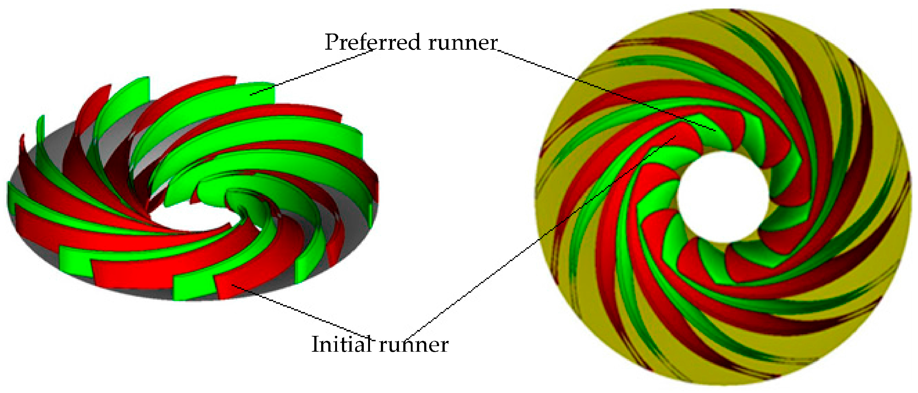
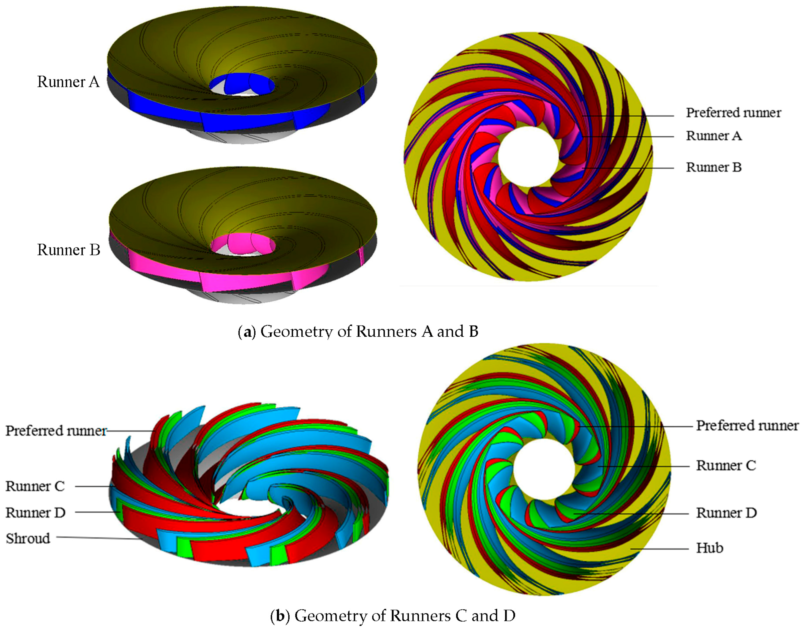
Figure 10 shows the comparisons of the shapes among runners A–D and the preferred runner. For runners A, B, and the preferred runner, their blade shapes are similar near HPS. As shown in
Figure 10b, the blade shapes are a little different near HPS for runners C, D, and the preferred runner because of a slightly different blade lean. Near LPS, the blade shapes of runner D and the preferred runner are similar, and the blades tilt more to the turbine rotation direction than the other runners.
According to
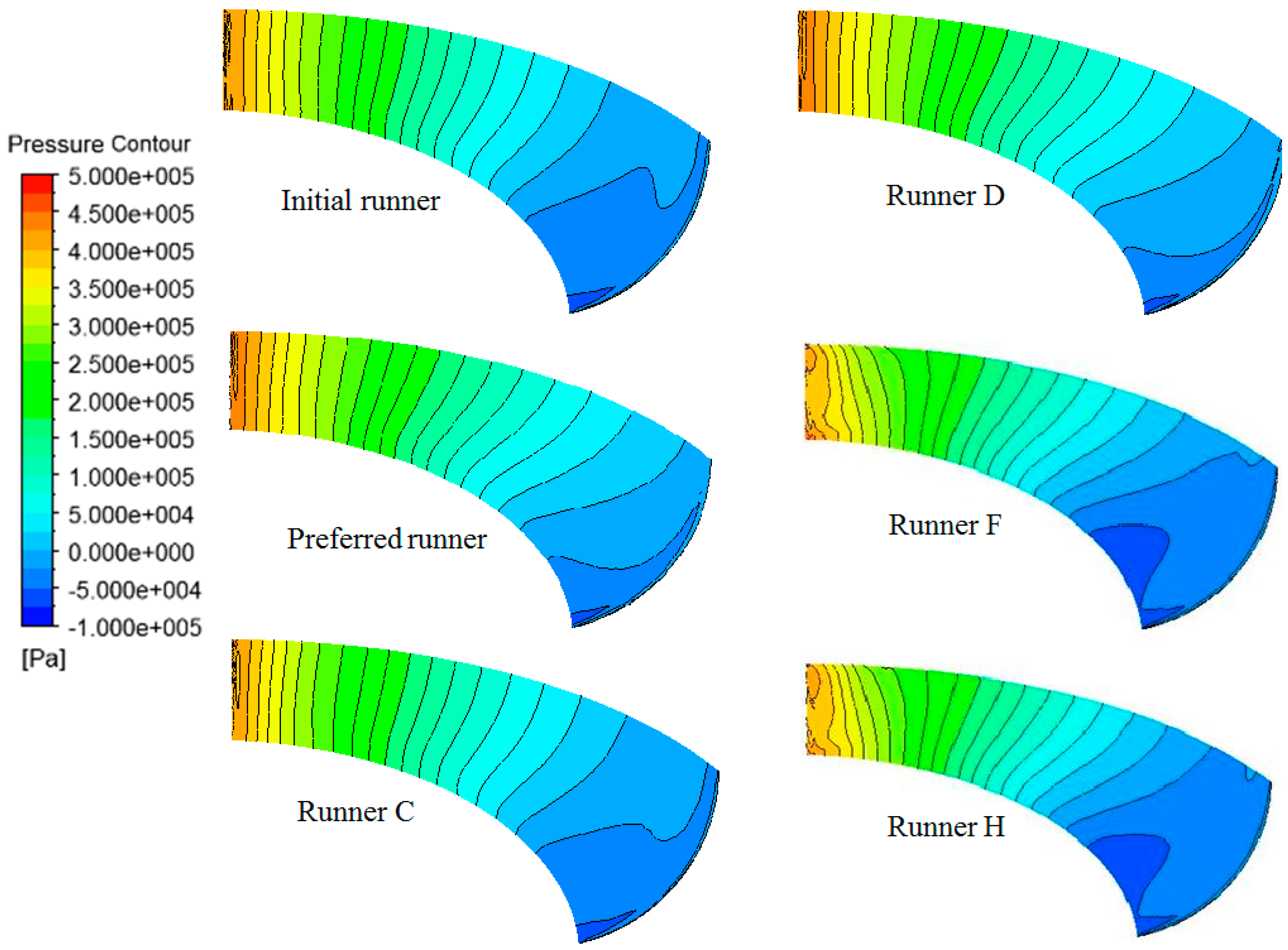
Table 6, the preferred runner and runner D have a higher efficiency in both turbine and pump mode. Furthermore, the minimum pressure at the blade surface is lower for these two runners.
Figure 11 shows the pressure distributions on the blade suction surface under pump mode for different runners. Smaller low pressure zones on the blade suction side in pump mode show that the preferred runner and runner D have better cavitation characteristics.
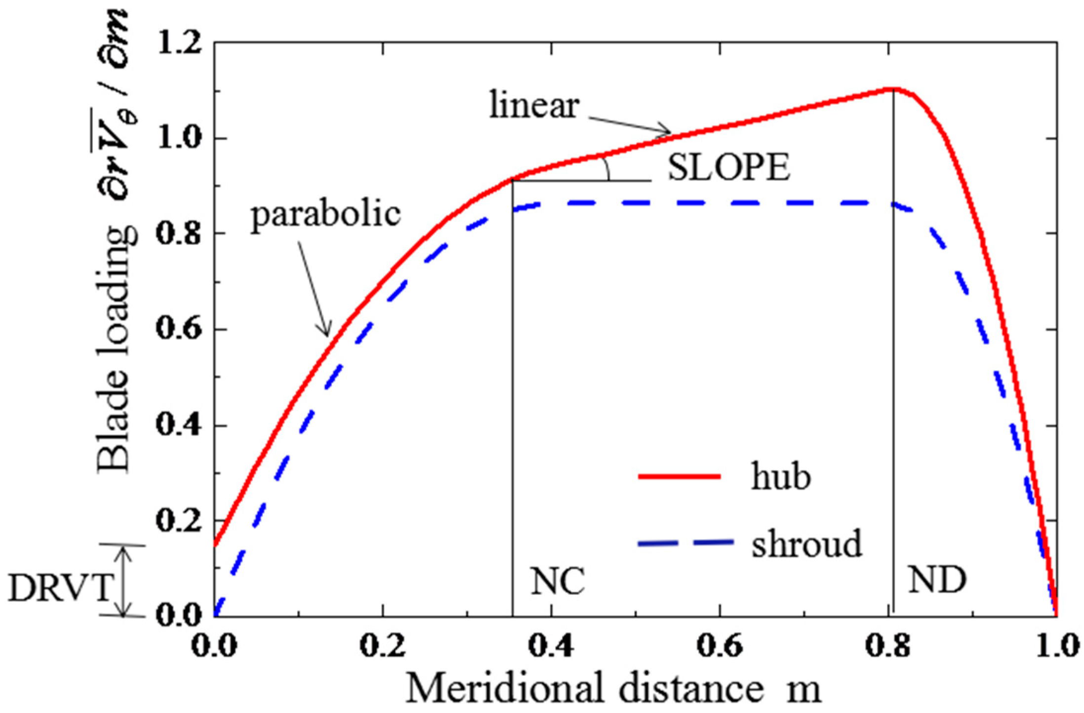
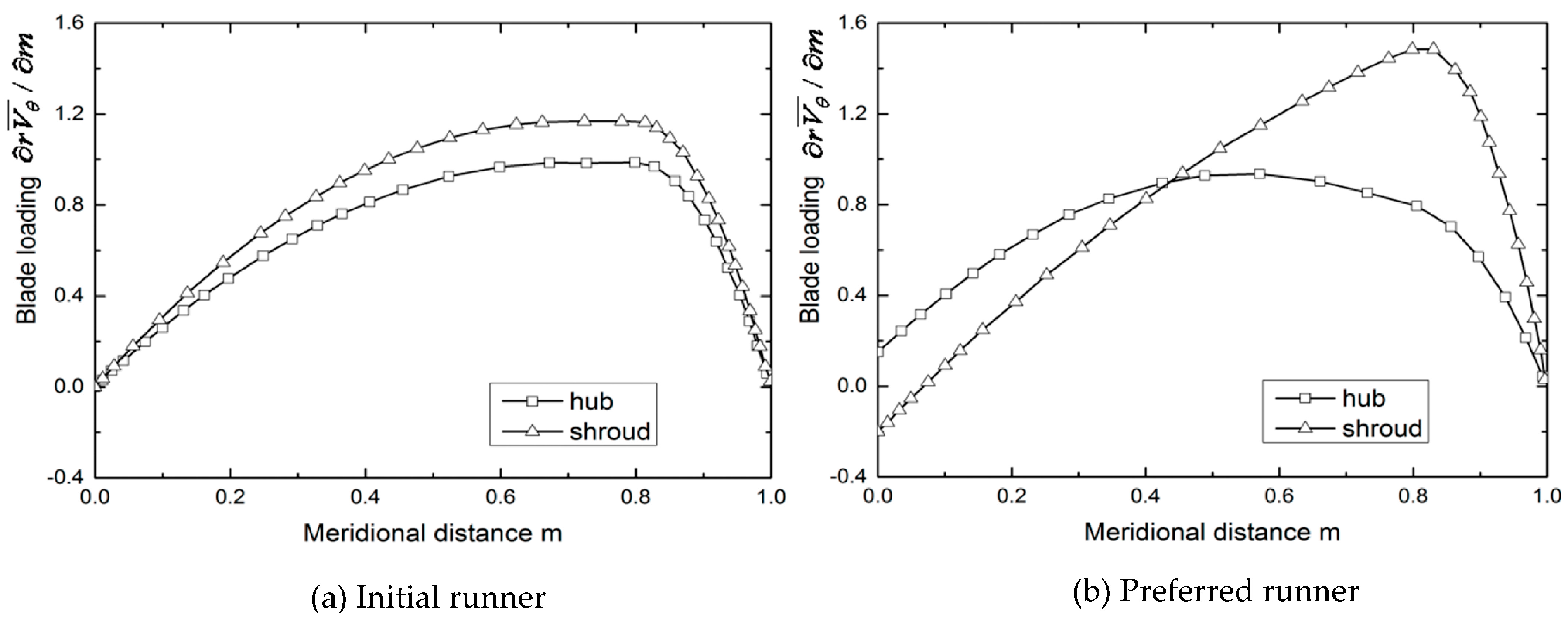
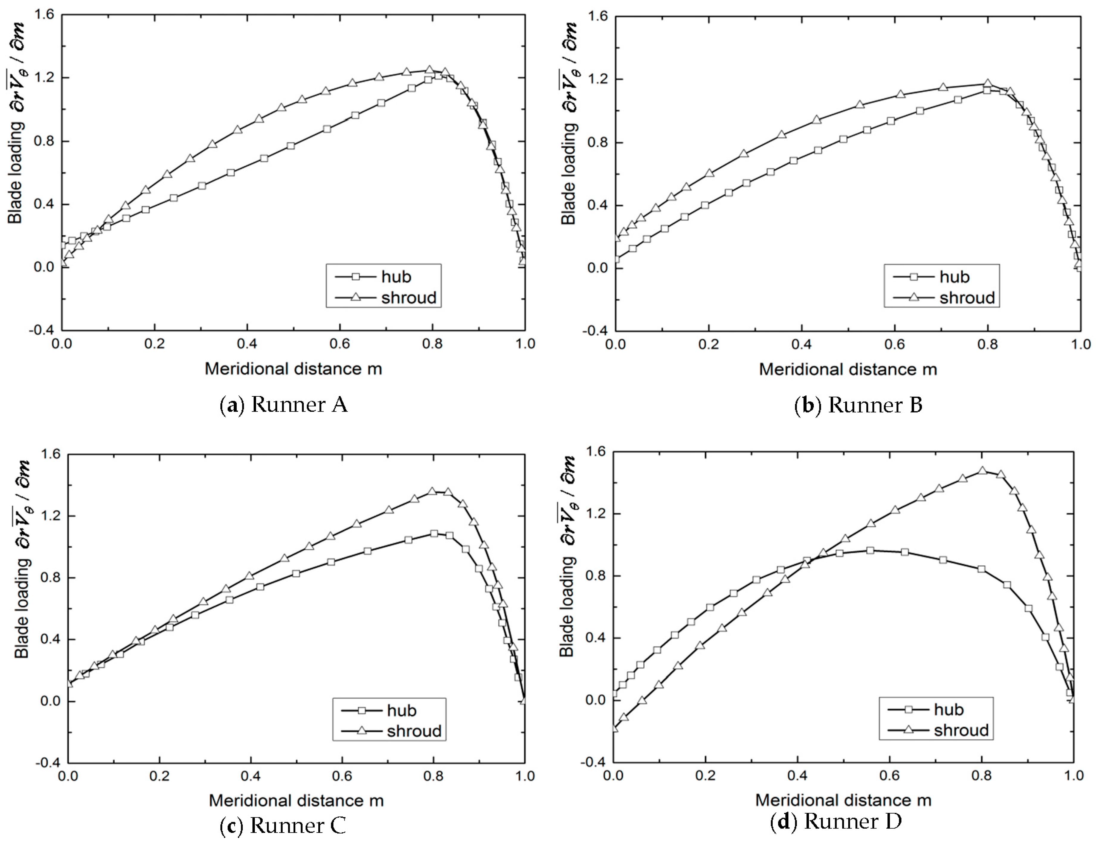
Figure 12 shows the blade loading for runners A–D. Blade loading distributions are aft-loaded on the hub and shroud for runners A, B, and C, similar to the initial runner in
Figure 7a. For runner D, blade loading distributions are middle-loaded on the hub and aft-loaded on the shroud, similar with the preferred runner shown in
Figure 7b. The preferred runner has same blade lean angle with runners A and B, meanwhile runner D has the same blade lean angle as the initial runner. Therefore, the performance improvement for the preferred runner and runner D is mainly provided by the blade loading distribution. Synthetically considering the effects on efficiency and cavitation, it is recommended to design the runner to be middle-loaded on hub and back-loaded on shroud for blade loading distributions.
4.2. Effects of the Blade Lean
More runners marked by E–H were investigated. For these four runners, the blade loading distributions were almost the same with the preferred runner and runner D, while the blade lean angles changed greatly,
,
,
, and
, respectively.
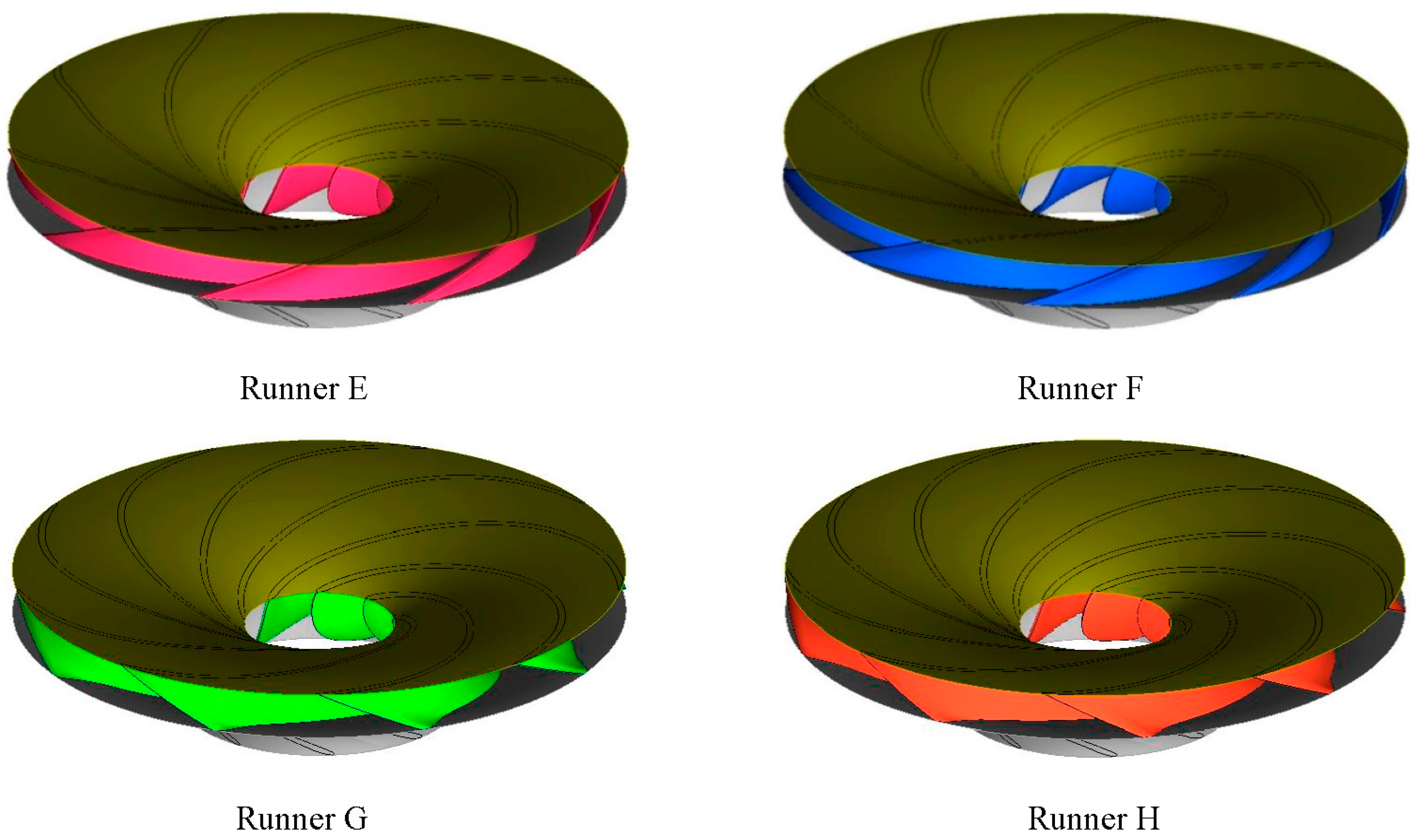
Figure 13 shows the shapes of these four runners. It can found that large positive or negative blade lean angles significantly change the spatial shape of the blades from shroud to hub.
Table 6 shows that runners E and F with large positive blade lean angle have a higher efficiency than the preferred runner and the initial runner in both turbine mode and pump mode. Runners G and H with large negative blade lean angles retain a relative high efficiency in pump mode, but the efficiency in turbine mode decreases. For all these four runners, the minimum pressure at the blade surface is lower than that of the initial runner and the preferred runner. It is clearly shown in
Figure 11 that low pressure zones on the blade suction surface for runners F and H are larger than those for the initial and preferred runner.
The cavitation characteristics of the runner mainly depend on the blade shape near the runner’s LPS. The blade loading for the preferred runner and runners D–H are almost the same, so that the large blade lean on the HPS induces the blade shape change near the runner’s LPS, and deteriorates the runner’s cavitation characteristics. Therefore, the large blade lean on the HPS is not recommended to be used for the ultra-head reversible pump-turbine runner considering cavitation characteristics.
5. Conclusions
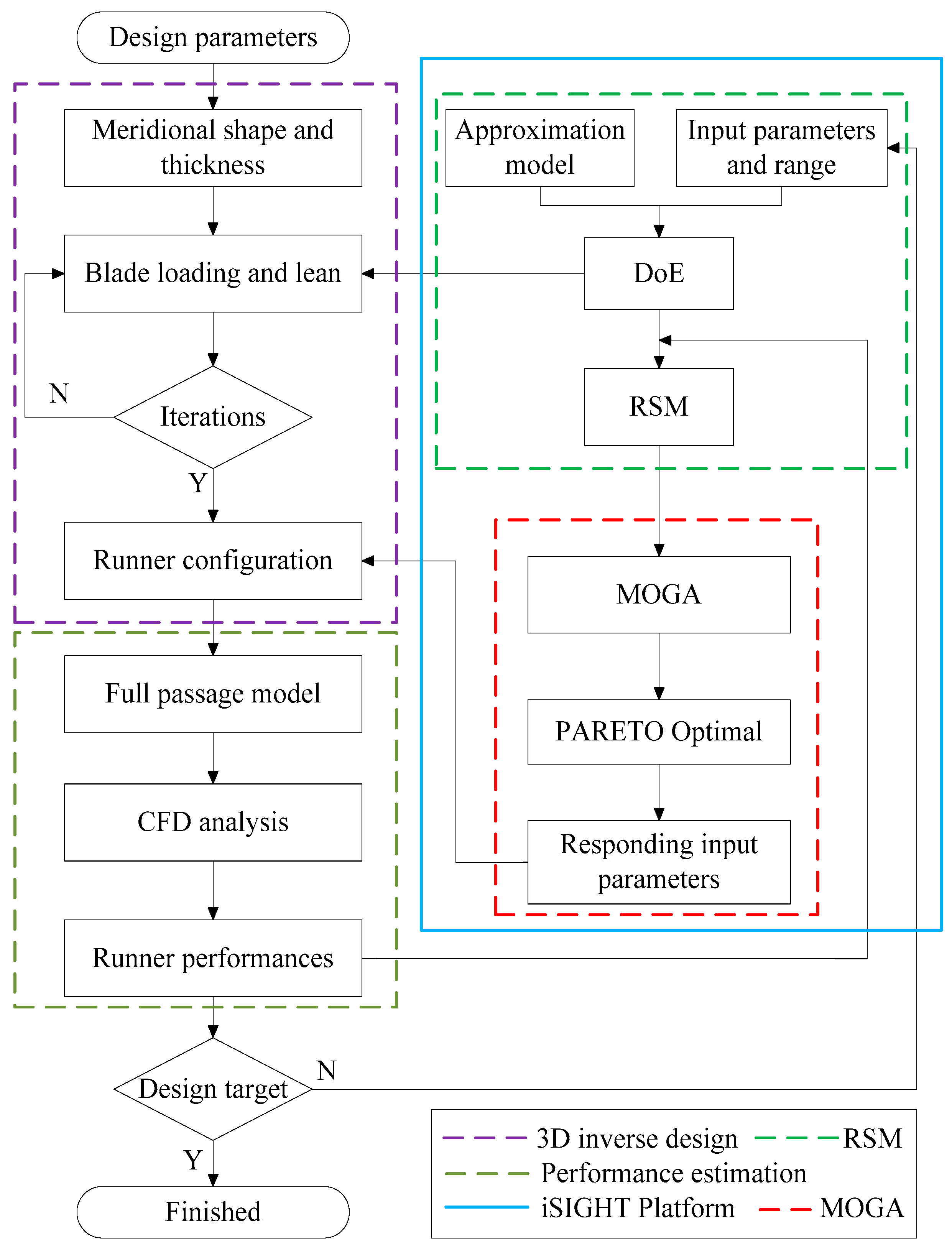
In the present paper, a multiobjective optimization design strategy is briefly presented. The design approach is a combination of 3D inverse design to parameterize the blade geometry, CFD for flow analysis, DoE to reduce the number of calculation times, RSM to correlate the design parameters with the objectives, and MOGA to search the trade-off design. The strategy is used to develop an ultrahigh-head pump-turbine runner. Based on the trade-offs among the optimized targets, a runner is recommended from the optimized runners. Compared to the initial runner, the preferred runner’s efficiency under turbine mode is increased by about 0.7% and the pump efficiency by about 0.6%, while the runner’s cavitation is greatly promoted.
The hydrodynamic performance characteristics of the pump-turbine correlate strongly with the design parameters. Based on the optimization, the effects of blade loading and blade lean on the runners’ geometry and performance are studied. It is suggested that middle-loaded blade loading distribution on the hub, and back-loaded distribution on the shroud—as shown in
Figure 7b—are good for the improvement for the runner efficiencies under two operating modes. On the shroud, the blade loading should be reduced near the LPS because the cavitation is most likely to occur in this zone. The large positive blade lean angle on the high pressure side can increase the runner efficiency under turbine mode. However, large blade lean angles may induce drop on the lowest pressure, and deteriorate the cavitation characteristics.
For the large capacity pump-turbine unit, besides the efficiency and cavitation performances, the operation stability for both operating conditions should be guaranteed [
3,
28]. Under pump mode, instabilities with cavitation in the hump region limit the normal operating range of the unit. Under turbine mode, pressure fluctuations mainly determine smooth operations for the unit. The flow field is converted into a fully separated unsteady state in these cases. Therefore, enlarging the present strategy to consider the unsteady characteristics of the pump-turbine would be valuable.


