Article

Design, Implementation and Demonstration of Embedded Agents for Energy Management in Non-Residential Buildings

1
Institute for Energy Efficient Buildings and Indoor Climate, RWTH Aachen University, Aachen 52074,Germany
2
Institute for Automation of Complex Power Systems, RWTH Aachen University, Aachen 52074, Germany
*
Author to whom correspondence should be addressed.
Current address: Gridhound UG, Aachen 52068, Germany.
Energies 2017, 10(8), 1106; https://doi.org/10.3390/en10081106
Submission received: 4 June 2017 / Revised: 18 July 2017 / Accepted: 21 July 2017 / Published: 29 July 2017
(This article belongs to the Special Issue ICT for Energy)

Abstract

:
With the building sector being responsible for 30% of the total final energy consumption, great interest lies in implementing adequate policies and deploying efficient technologies that would decrease this number. However, building comfort and energy management systems (BCEM) are challenging to manage on account of their increasing complexity with regard to the integration of renewable energy sources or the connection of electrical, thermal and gas grids. Multi-agent systems (MAS) deal well with such complex issues. This paper presents an MAS for non-residential buildings from the design, implementation and demonstration, both simulation based and in a field test. Starting from an ontology and an attached data model for BCEM application, we elaborated use cases for developing and testing the MAS framework. The building and technical equipment are modeled using the modeling language Modelica under Dymola. The agents are programmed in JADE and communicate with Dymola via TCP/IP and with the real devices via BACnet. Operatively, the agents can take on different control strategies: normal operation with no optimization, optimization of energy costs, where energy is delivered through the room through the devices that have the lowest operating costs, and relaxation of the comfort constraint, where the costs of the productivity loss under sub-optimal comfort conditions is taken into account during optimization. Comfort is expressed as a function of indoor air temperature. Simulation, including a comparison with a benchmark system, and field test results are presented to demonstrate the features of the proposed BCEM.

1. Introduction

Buildings account for over 30% of the total final energy consumption for all sectors of the economy and for 50% of the global electricity demand [1].
Fortunately, the energy savings potential in the buildings sector is substantial. Globally, the  wide deployment of best available technologies and efficiency policies could yield annual savings in building final energy use in the range of 53 EJ by 2050. Compared to continuing on the current path both technology and policy wise, this would mean a 29% reduction in projected building energy consumption [2].
Apart from the building materials and installed equipment, a high impact on the operation efficiency of the building falls on the control concept and implementation for its energy system. Buildings energy systems are becoming more complex, through integration of renewable energy, diverse energy generation, distribution and delivery systems, or the integration in a smart grid. While these conditions expand the possibilities of formulating a control problem, they also make it more challenging. Non-residential buildings with complex energy systems often do not reach the expected energy efficiency and indoor comfort because of lack of effective coordination between resources (coordination of when, how long and how much each device should operate) and because of implementation issues of the centralized control system (flaws in wiring and setting). Multi-agent systems (MAS) offer a solution for this kind of problems due to their distributed and autonomous properties.
A synthesis of the current literature on MAS automation in buildings is available in two recently-published reviews. The authors in [3] look at control optimization methodologies for building energy systems and identify MAS along with model predictive control (MPC) as the most promising, with MPC being the most widely researched. Secondly, the authors in [4] look specifically at MAS and identify rule-based and market-based control as the two control principles most associated with MAS. Furthermore, the authors suggest focusing on ontologies as a first step when building up MAS. However, to our knowledge, no study presents a complete process of development and testing the system from the concept, reinforced with an ontology and attached data model, all the way to testing in a simulation environment and transfer to a field test. Our paper strives to do exactly this.
In this paper we research a MAS solution that moves away from a centralized building automation system, which requires a lot of dedicated hardware and software as well as know-how in setting up. Following the classification in [5], we develop “utility-based agents” that posses a utility function, which the agent uses to evaluate different situations and to take decisions to improve the current state of the system. The goal of the agents in this work consists in mediating the trade-off between energy savings and occupant comfort, which for non-residential buildings directly correlates with productivity. The agents reach their goal through a process of negotiation based on energy and comfort costs. We use the indoor air temperature as a comfort criterion.
The main contributions of our study are:
  • providing an ontology for MAS in buildings and a data model for the application to non-residential buildings, both of which were developed with a focus on existing standards and are re-usable and expandable
  • presenting a validation platform, which allows a swift transition from simulation testing to a field-test experiment
  • assessing the feasibility of embedding the agents in the intelligence of the energy components, by programming them on BeagleBone Blacks using Java
The paper continues with a presentation of the concept (Section 2) including a description of the ontology and data model. Only aspects relevant to the understanding of the use cases are included in this paper, with additional details to be found in [6]. Section 3 deals with the design and implementation of the developed use cases, the agent platform, the simulation models and the cost functions, which build the basis of the agent negotiation. Section 4 details the validation concept including the used evaluation criteria, which were applied to a simulation test, a field-test experiment and the presentation and discussion of the results for exemplary test cases. Conclusions close the paper.

2. Concept

The goal of this work is to develop a methodology for MAS for non-residential buildings (particularly office buildings), by starting from an ontology and by focusing on the application on non-residential buildings adding a data model. Further pursuing our validation and demonstration options we developed use cases for different system functionalities: normal operation including optimization of energy costs and relaxation of comfort constrains, and plug-and-play.
We start from the idea that each office has a room agent in charge of monitoring the indoor comfort and negotiating the delivery of additional energy to the room, in case the comfort needs to be improved. The goal of the person working in that office, the occupant, is optimal comfort conditions, which in return insure optimal productivity. The occupant’s interests are represented by a comfort agent that has knowledge of the his/her preferences and productivity function (depending on indoor temperature). In order to assess the current comfort conditions the comfort agent gets information from temperature sensors, in the room as well as outside. Each energy generation and distribution device in the building is equipped with an agent, called energy supply agent. When the room temperature needs to be increased or decreased, the room agent sends a call for proposal (CFP) to these energy supply agents. The energy supply agents analyze their current operation point and decide whether or not they can provide the needed energy and at what costs. The room agent chooses the most cost effective solution.
The energy supply agents can determine on their own if they can supply energy to the room where the call comes from, by analyzing their location in the energy system of the building. Based on their data model, agents can belong to rooms or to supply circuits, whereas a room can be connected to several supply circuits (heating, cooling, ventilation). A room agent has knowledge of the supply circuits it is connected to and as such only sends CFPs to agents connected to the same circuits. When energy supply agents need sensor measurements for internal power and energy calculations, they identify the relevant sensors by matching the names of the supply circuits the sensors are located on with their own supply circuit. Based on the current operating point of the device and data received from sensors, the energy supply agents are able to calculate the power and energy they can supply. They do this by using data of the characteristic diagram of the devices, which is provided as part of the data model. We developed the data models based on data required to be included in manufacturer data sheets in order to ensure re-usability of the framework when using different types or brands of components.
When comparing our concept with existing ones, the most relevant is PowerMatcher [7], which is a smart grid coordination mechanism, matching electricity supply and demand. The main differences between the two concepts are:
  • the different kind of energy supply agents in our systems, not all of them necessarily electrically powered (e.g., a boiler)
  • the choice of energy supply agent based on merit order, and not a market price
  • basing the concept on an ontology with attached data model for our application
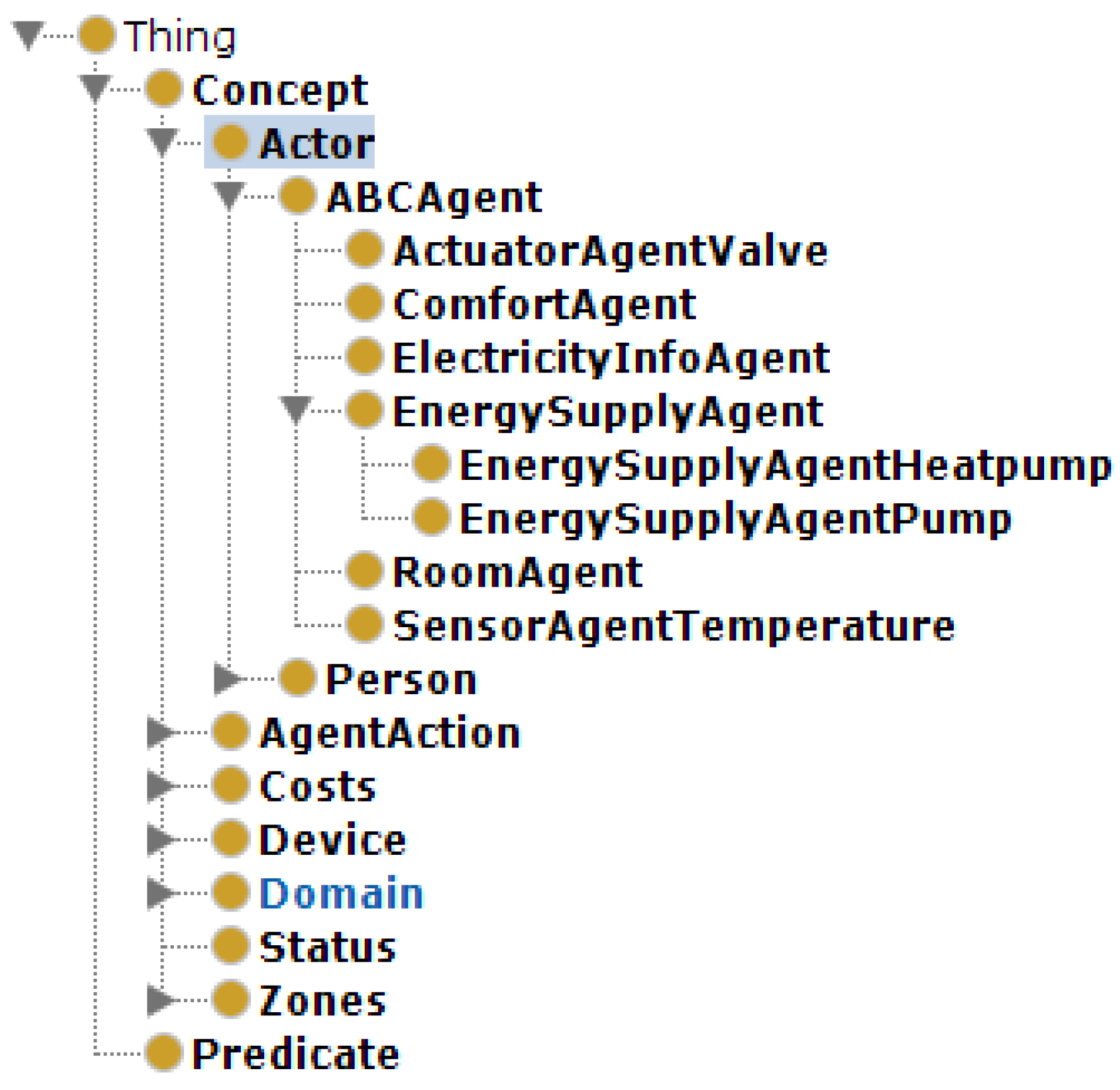
We believe the more complex nature of our concept allows us to test different use cases and provides a large spectrum of design choices, which can be used for different configurations of BCEM systems, which go beyond matching supply and demand as is the case with PowerMatcher.

2.1. Ontology

An ontology is a an explicit formal specification of the terms in the domain (in our case agent systems for building comfort and energy management) and relations among them [8]. On the other hand a data model describes the structure and integrity of the data elements of the specific application in which it will be used [9].
For defining the ontology for MAS for energy management in buildings suitable for the use cases in this work, we use the approach from [10], which focuses on re-using existing ontologies and development using an iterative process for classes and relationships definitions. We used Protégé [11] for building the ontology.
As a first step we researched existing ontologies, ideally which are already used as standards. After our survey we build our ontology using know-how from the following sources: [12,13,14] as well as several FIPA (Foundation for Intelligent Physical Agents) standards [15,16].
We developed an ontology in Protégé called MASforBECM, meaning ontology for multi-agent systems for building energy and comfort management. The main classes of the ontology, with a detailed view on the ABCAgent class are presented in Figure 1.
As we implement our agents using the Java based application JADE (Java Agent DEvelopment Framework) [17], which in its turn support the use of ontologies, several upper level classes are the from JADE: concept, predicate and agent action.
We classify the devices in controllable and uncontrollable, to offer a basis of deciding on which devices an agent should be embedded.
In analogy to the classes from the Smart Grid Architecture Model (SGAM) [14] we developed the following classes in our ontology:
  • Domain: generation, distribution, storage, delivery, customer
  • Zone: building, process, supply circuit, room. The supply circuits are of several types: electrical, air, hot/cold water
The agents along with the real people using the building belong to the class Actor.
As the costs are the basis of the negotiation between agents, there are different types of costs considered: current operation costs, gradient costs for increasing or decreasing the supplied energy, as well as startup or shutdown costs.
Besides the entity tab of the ontology, shown in Figure 1, there are data and property tabs to be defined for each class. These are the basis for the data model (data tab) and for the definitions of the functionalities for the JADE implementation (the properties tab).
We build our ontology mainly for descriptive purposes in order to offer support in the next phases of the project, when developing the behaviors of the agents according to different use cases. However, the ontology can be further used for queries, and in the case of full ontological support for the agent behaviors, it can aid the agents in deciding on their own what the best course of action is. For example, by understanding that a sensor measures the room temperature and the room temperature has a direct influence on the comfort level of the occupant, a room agent would on its own look for a temperature sensor in the room to evaluate the comfort level. In this implementation, each agent behavior is defined in detail; however, more sophisticated reasoning for the agents to make inferences is a possible alternative supported by this ontology.
The ontology supports all of the use cases developed. Additionally, it supports a wider array of energy equipment, than tested in the use cases, for example radiators, floor heating, fan coils and facade ventilation units for energy delivery, or combined heat and power, boilers and heat pumps for energy generation.

2.2. Data Model

When developing the data model, we looked for standards compatible with our application. The resulting data model uses parts of the Neighborhood Information Model from the project on Semantic Tools for Carbon Reduction in Urban Planning (SEMANCO) [18], the International Electrotechnical Commission (IEC) standard IEC 61850 [19] and the Industry Foundation Classes (IFC) [20].
The data model describes the agents in the system. If the agent has an attached device, information on the device functionality is included in the data model. For our application we used the property types from the IEC 61850 standard, but aggregated them into four categories:
  • Descriptions, containing information on name, type, model, energy data, domain, zone and fixed energy costs.
  • Measured and metered values, containing information on energy data such as current operation point, delivered energy and variable energy costs.
  • Settings and controls, providing information on the type of communication used by the agent to the device (TCP/IP, BACnet), control mode of the device and set point types.
  • Status contains information such as heating or cooling mode and information on the health of the device (ok, alarm, waning, out of service).
Table 1 presents a part of the data model for a heat pump regarding the measured and metered values, including the relevant costs to be sent to the room agent in a CFP: relevantCost.
The data models were developed starting from the ontology and according to the target application. The spectrum of the application was defined on a use case basis, so the models were developed along with the use cases.

3. Design and Implementation

3.1. Use Cases

The use cases are detailed according to the specifications of [21,22], with primary use cases focusing on monitoring, normal operation and plug-and-play. For normal operation, we looked at a one room, as well as multiple room scenarios. We further differentiate between one occupant and multiple occupant scenarios. For normal operation, we defined three control modes:
  • Default, meaning the comfort conditions must be satisfied in the room, without further constraints.
  • Optimization of energy costs, where only the most cost effective energy supply option to the room is executed.
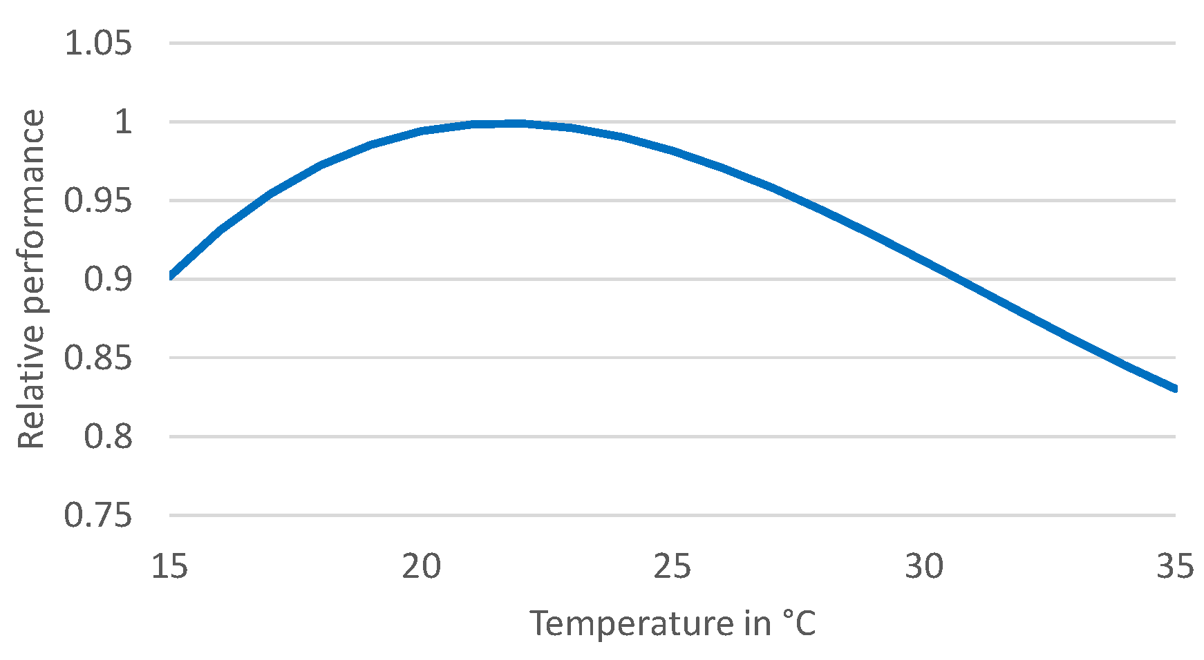
  • Relaxation of the comfort constraint, where the possible productivity gain from increased comfort is compared to the energy supply costs for achieving this comfort level. The energy is supplied to the room, only if the monetary productivity gain is higher than the energy supply costs.
In the considered use cases, thermal energy is supplied to the office via a medium flowing through a system component (e.g., a facade ventilation unit which can both heat and cool). The energy consumption is calculated from the mass flow of the medium and the temperature difference between flow and return temperatures for that component. The temperature in the medium is provided by a central system component (a heat pump). The mass flow through the energy delivery component is controlled by a valve, with a circulation pump moving the medium through the supply circuit. We assume that two temperature sensors (supply and return) are available for each room on the supply circuit of the circulation pump, in order to be able to calculate the energy costs for the pump.
Figure 2 presents the set up of the energy supply system for two rooms (Room1 and Room2) and the involved agents. The numbered arrows describe the communication flow between the agents. We start with the one room scenario, by considering only Room1. The steps in the one room use case with the control strategy “optimization of energy costs", are the following:
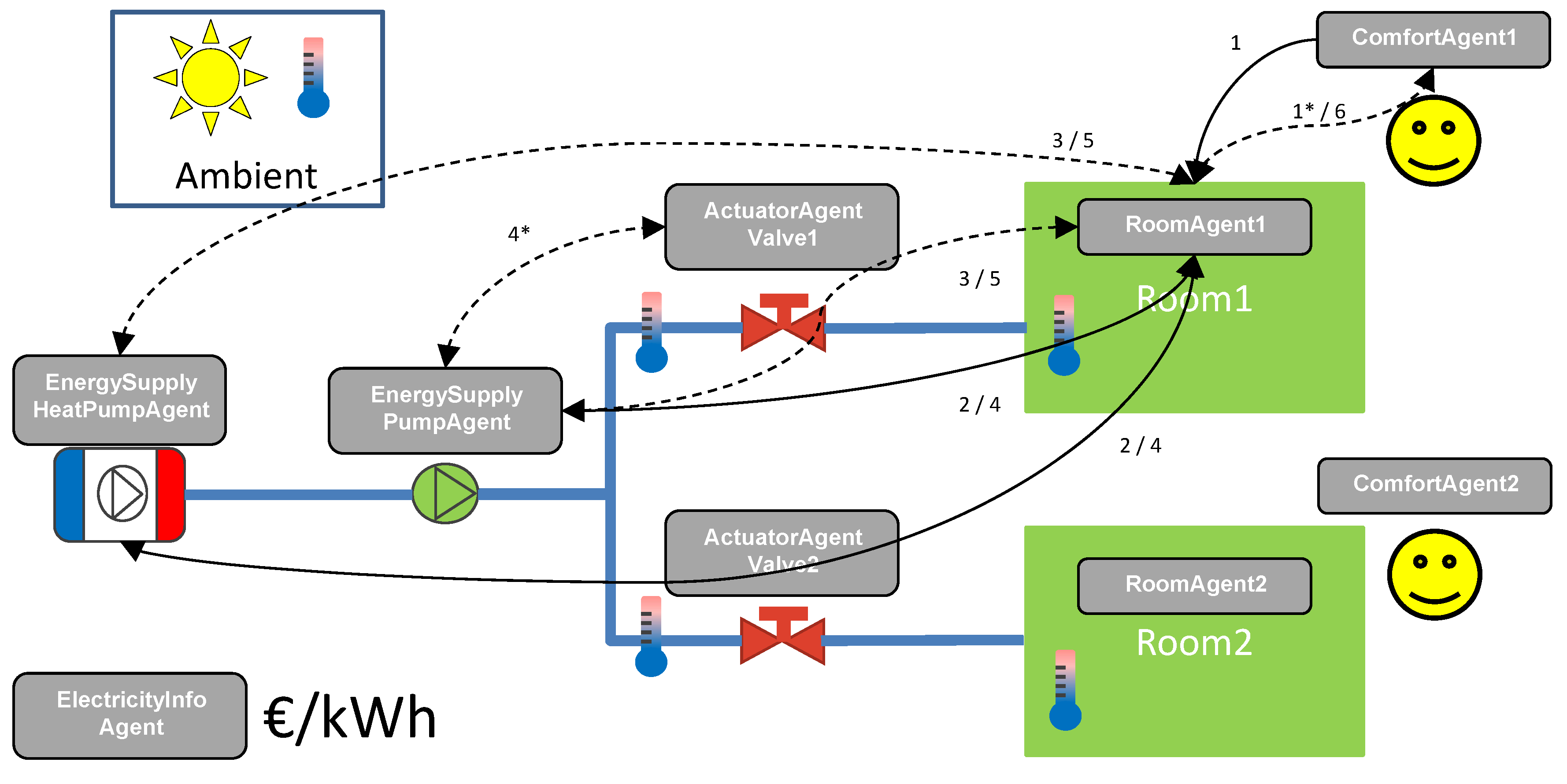
  • The room agent monitors the room temperature (received from the sensor) against the desired room temperature (received from the comfort agent-arrow with number 1). If the room air temperature lies outside a tolerance interval around the desired temperature, a call for proposal is send to the relevant energy supply agents that are connected to the supply circuit of the room and can supply energy (heat pump and circulation pump) (2). Additionally a request for the comfort costs is send to the comfort agent (1 *).
  • The energy supply agents send their costs and the amount of power they can produce (3).
  • The room agent compares the costs for supplying the energy against each other. The option with the lower costs is executed.
  • If energy can be provided to the room, the room agent sends a request to the energy supply agent with the lowest costs (4). In this use case the pump, if chosen, will forward the request to a valve that can directly control the volume flow (4 *). Once the action is performed the valve sends a confirmation back to the pump (4 *).
  • The energy supply agent sends an inform message to the room agent on how the command was executed (5).
  • The room agent informs the comfort agent on how the action for improving the room conditions was executed (6).
When using the control strategy “relaxation of comfort constraint”, the energy supply costs are compared to the comfort costs of the user. The comfort costs express how much the loss of productivity of the user costs as a result of suboptimal comfort conditions in the room. If the comfort costs are higher than the energy supply costs, energy will be supplied to the room.
When dealing with multiple persons present in a room, we differentiate between “owner” and “guest”, where the “guest’s” preferences are not considered and preferences of multiple “owners” are aggregated. The aggregation means building mean values for the optimal temperature and summation of the comfort costs.
The case of multiple rooms is solved by enabling an energy supply agent (e.g. of a heat pump) to understand that it will be supplying multiple rooms, as soon as it receives requests from different rooms in a short period of time. As long as the requests are complementary, the agent calculates the energy delivered to each room and the corresponding costs. Afterwards, the use case follows the one room use case. If the requests are contradictory, the agent decides not to act, allowing other agents (e.g., of a circulation pump), which are better suited for distributed energy delivery, to act.

3.2. Demonstration

We chose for demonstration the office rooms in the main building of the E.ON Energy Research Center in Aachen, Germany [23], with simulation models of these office rooms being set up.
The climatization concept of an office room has two main components: the base load of the thermal demand is covered by the concrete core activation installed in the ceiling, while the peak load is covered by a facade ventilation unit installed in the outside wall, behind a metal facade. Both components can cool and heat, while the facade ventilation unit has an additional air ventilation capability. The control variable at room level is the room set temperature, used by the facade ventilation unit. The concrete core activation has no valves on room level, and it has a slower dynamic than the facade ventilation unit. The energy generation unit is a heat pump and the energy distribution unit is a circulation pump, just as in Figure 2. The MAS includes both the circulation pump in the supply circuit of the facade ventilation units, as well as the central heat pump. Adding an agent for the pump of the concrete core activation circuit is theoretically possible. However it would require extra routines for identification of the difference in the time constants of the two supply systems, which are not part of considered use cases for the proof of concept. The demonstration was done for one and two rooms use cases, with both offices next to each other, having the same orientation and number of occupants.
For a new building, the data model and the ontology have to be populated by using information on the design of the energy system and a description of the pieces of technical equipment. Knowledge on energy systems is required to do this. We have developed a methodology for extracting the necessary information from manufacturer data sheets, which is explained in more detail in Section 3.5. Once the necessary data is made available setting up the ontology and the data model does not take long, for example one day for the two room use case presented in this paper.

3.3. Agent Platform

We developed the agents in the Java based programming language JADE to develop the agents. The decision for JADE was made based on previous knowledge of working with the software as well as its implementation of the FIPA specifications.
The JADE platform can support multiple agent containers and provides them with basic services such as message delivery. Containers can be executed on different hosts thus achieving a distributed platform. Each container can contain none or several agents. This makes the platform ideal for programming agents embedded on different devices.
Agents can communicate with each other, regardless of the container, host or platform on which they are located. The communication is based on an asynchronous message passing paradigm. The message format is by FIPA standards and contains a number of fields including:
  • the sender.
  • the receiver(s).
  • the communicative act that represents the intention of the sender of the message. The FIPA standard defines 22 types of communicate acts, with the most used being: INFORM. REQUEST, CFP. We used only the types of communicate acts defined by FIPA.
  • the content i.e., the actual information included in the message.
Exemplary for the behaviours of an agent, we present those of a room agent (Room Agent). The Room Agent evaluates the room conditions based on parameters provided by the comfort agent (Comfort Agent) of the room’s occupant. If required, the Room Agent starts to negotiate the improvement of this conditions with the relevant energy supply agents (Energy Supply Agents).
Behaviors:
  • Analyse Room Conditions: this behavior is always started if new data is received in Handle Temp Sensor Data Subscription and it is not already running. It analyses and evaluates the current room conditions. If improvements are required, it starts the Initiate Contract Net For Energy Supply behavior. If comfort costs are to be considered, Initiate Prod Loss Cost Request is started first.
  • Update Room Characteristics Ticker: this behavior updates the room characteristics (thermal capacity and resistance) every 15 min.
  • Handle Comfort Agent Subscription: this behavior is initiated whenever a Comfort Agent registration is detected. This behavior receives and handles the notifications from the publishing Comfort Agent it subscribed to. A Comfort Agent General Data structure is transmitted from the Comfort Agent.
  • Handle Electricity Info Subscription: this behavior is initiated whenever an Electricity Info Agent registration is detected. This behavior receives and handles the notifications from the publishing Electricity Info Agent it subscribed to. The electricity price is transmitted from the Electricity Info Agent.
  • Handle Temp Sensor Data Subscription: this behavior is initiated whenever a Sensor Agent Temperature registration is detected. This behavior receives and handles the notifications from the publishing Sensor Agent Temperature it subscribed to. It triggers the Analyse Room Conditions behavior every time a temperature update is received.
  • Initiate Shut down Request: if the last Comfort Agent deregisters from the room, this behavior is initiated, to send a shutdown request to the Energy Supply Agents. It is triggered from Auto Subscribe To Comfort Agent.
  • Initiate Prod Loss Cost Request: this behavior sends a request to the Comfort Agent to get the costs, the current conditions create, due to reduction in productivity. It also handles the answer.
  • Initiate Contract Net For Energy Supply: this behavior is initiated from Analyse Room Conditions, if there is a need to improve the room conditions. It starts a CFP to the Energy Supply Agents, evaluates the proposal requests the execution of the proposal.

3.4. Cost Functions

Cost functions for heat pump and pump
We consider only the current operation costs as the relevant costs for negotiation in a call for proposals. When a CFP comes in, it includes the information on the needed thermal power to improve the room conditions. This additional thermal power would lead to a change of the current operation point of the device. To reach this new operation point, the device has to consume more power (electricity in the case of a circulating pump or heat pump, gas in the case of a gas boiler). This needed power for the device is communicated to the room agent. The room agent has contact to agents that posses knowledge on resource prices (in our case the Electricity Info Agent knows the current price of electricity). Using the information on needed power by the device, the information on the resource price and using the relevant time interval an energy price can be calculated. This price is expressed in € per hour.
C e n e r g y = C · S T · P
where C means costs, ST means sample time (in our case 15 min) and P means power.
Cost function for comfort agent: The productivity of a person is directly influenced by the indoor conditions of the work space. Each person has his/her own preferences. We use a productivity function depending on indoor room temperature according to [24] :
P = 0.1647524 · T - 0.0058274 · T 2 + 0.0000623 · T 3 - 0.4685328
where P is the productivity relative to a maximum value and T is the room air temperature in C. Figure 3 shows the curve of the productivity against the room air temperature according to the equation above. We further extended this model, by centering the maximum productivity on the current optimal temperature for the room. This is a function of outside temperature, meaning in winter the optimal temperature is lower than in summer.
The costs for loss of productivity are calculated by multiplying the productivity loss with the hourly wage rate of the person. The resulting comfort costs are expressed in € per hour. In this way energy costs and comfort costs are directly comparable.
While additional comfort criteria such as CO 2 concentration, lighting or noise exist, air temperature sensors, as well as an air temperature control mechanism are more readily available in buildings, including our demonstration building. Furthermore, studies exist that correlate room air temperature explicitly with productivity, such as the one we used, which in turn allows for the calculation of comfort costs. The productivity function presented here can however be easily extended to include other indoor comfort criteria, if measurements, control mechanisms, as well as a function correlating with productivity are available.
We allow for the occupant to setup his/her own productivity curve. In the field test, the occupant gets direct feedback via a web interface on how high the comfort costs are, based on the current conditions and the function he/she has provided.

3.5. Simulation Models and Set-Ups

Simulation models were build to test the concept and test and develop the agent behaviors. The main limitation of the simulation testing is the perfect communication between the simulation models and the agents, since the simulation can send and receive messages from the agents without a problem. In order to address the communication of the agents with real devices a field test was set up. In order to insure a smooth transfer of the agent platform from simulation to a field test, special care was taken when defining the information agents exchange with the devices (real or simulated): only data available in the field test (measurements and set points) are used when setting up the simulation models and developing the behavior of the agents. The main difference between the simulation and the field test is the communication channel: TCP/IP in the simulation and BACnet [25] in the field test.
The simulation models were developed using blocks from the Modelica Standard Library, the open-access library of the Institute for Energy Efficient Buildings and Indoor Climate, AixLib (https://github.com/RWTH-EBC/AixLib), and an internal Modelica library for components for energy systems.
The following models were used and/or developed:
  • Technical equipment: heat pump, boiler, circulating pump, radiator and fan coil (as a model for the facade ventilation unit)
  • Building: room with walls, windows and doors
  • Internal gains from persons present in the rooms
  • Boundary conditions, mainly weather model
More information on the modeling principles, the communication between JADE and Dymola and the particularities of adjusting the dynamic of the agents systems to the simulation are to be found in [26].
Models for technical equipment are usually parametrized using records, which are an aggregation of relevant parameters. A boiler record might include for example information on the water volume of the boiler, and an equation describing the pressure drop over the component, etc. The equation is usually derived from drawings found in manufacturer data sheets. When deciding on the detail of the models for the controllable pieces of technical equipment, we decided to make them as complex as the available manufacturer data allows us to. For this, we studied data sheets for similar components from different manufacturers. We did this especially for heat pumps and circulation pumps with an additional focus on the current standards, which compel the manufacturers to make certain data available. The idea was to have a methodology in place that will allow future users to test our MAS on other energy system configurations, with different devices, which the user could still provide based on manufacturer data the information needed to make the necessary calculations, e.g., the current power and associated costs. Both the attributes for the agents in JADE and the records for the device models in Modelica are based on the developed data model.
An additional adaptive model of the room as a first order RC-circuit was built and used by the room agent to approximate the energy needed by the room to change to a desired temperature. The R component describes the losses of the room to the exterior, and the C components describes the thermal mass of room. The coefficients are regularly adapted with current temperature measurements, and the final values are obtained by doing a moving average over a desired period of time (e.g., one hour). With this model, effects like opening a window (change in R value) or the presence of other persons in the room (change in C value) over longer periods of time can be accounted for.
In this paper, we present the setup for a two room use case with the control done by the multi-agent system. The setup corresponds to the one described in Figure 2. The rooms are both connected to energy supply circuits on which both a circulating pump and a heat pump are connected. The control of the flow to each room is done by valves. There is one occupant per room, who is also the owner of the room.
In order to better evaluate the results, we use a benchmark system for comparison. As the benchmark we use the same building and energy system setup, but with the following control strategies for the technical equipment, which are commonly used for this type of system:
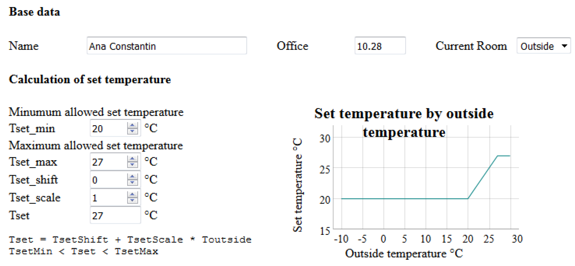
  • the supply temperature for the heat pump is set according to a heating curve, depending on outside air temperature and the characteristics of the building
  • the room temperature control is done via thermostatic valves

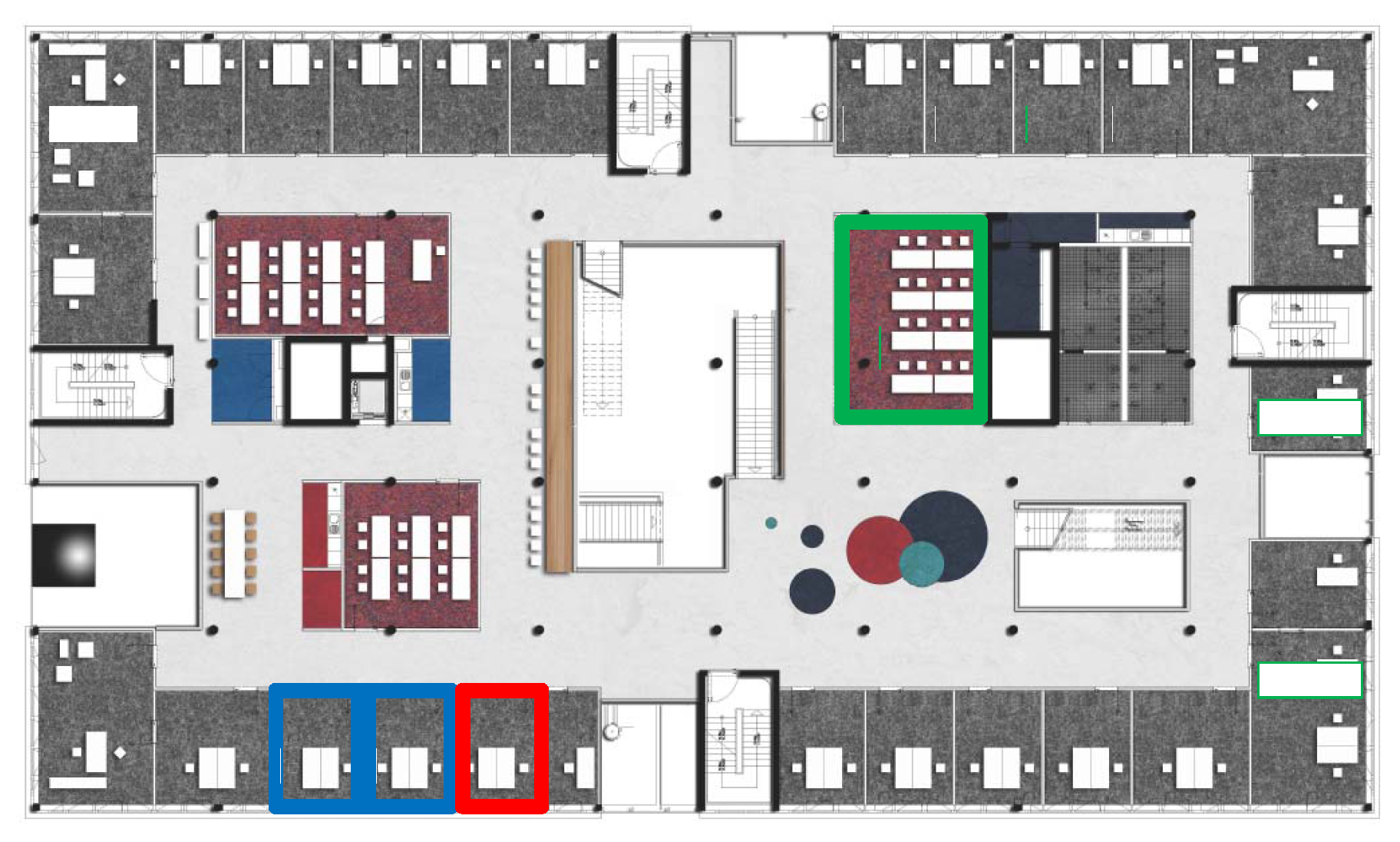
3.6. Field Test Set-Up

A field test was important to run for the following reasons:
  • to test the communication between agents and their devices in a real network, where unexpected delays or failures may occur
  • to test the system with real technical equipment in a real building
  • to allow for a more dynamical interaction with the user
The field test implementation faced us with several challenges.
Challenge 1: direct communication with the technical equipment:
We wanted the agents to communicate directly with the technical equipment. The demonstration building is equipped with an extensive monitoring system, with the data points listed on an OLE (Object Linking and Embedding) for Process Control (OPC) server and continuously logged in a data base. However the access over the OPC server would mean using an intermediary central service, which is not always available in non-residential buildings, restricting the demonstrated applicability of our solution. Additionally embedded agents would get data directly from the device they are embedded on, and not from a central data base. As a direct communication method we decided to have the agents communicate with the attached devices over the BACnet protocol, which strives to be the most comprehensive standard in the building automation field and enables direct communication with the devices, with no intermediary server or data base. The routines for reading and writing data points are implemented in JAVA using a BACnet stack implementation called BACnet4J. The Java implementation was needed for compatibility with JADE, which is also Java based.
Challenge 2: Agent distribution:
In order to have an distributed, embedded system we deployed the agents on BeagleBones Black(BBB), which are low-power open-source hardware single-board computers with 512 MB RAM, a processor running at 1 GHz and 4 GB of flash memory. For the one room use case we need a total of 16 agents and for the two rooms use case we have a total of 31 agents. We had nine BBBs available, and in the two room use case, we needed to place 31 agents on them. Table 2 shows what agents were placed on each BBB. Since part of the field test was carried out in autumn, when outside temperature can require cooling of the office building, we also consider the cooling supply circuit: one central circulation pump, one valve and two temperature sensors per room. Additionally each room has two occupants, which are both owners of the room.
We grouped the comfort agents and the actuators each on one BBB, as these type of agents do not communicate with each other, and as such, for the agents with which they do communicate, no difference exists if they are on the same or on different BBBs. The grouping of the sensor agents on the same BBB is in part motivated by the same argument. Additionally, we consider that for further work on this platform, it would be advisable to have just one agent in charge of all of the sensors.
All agents belong to one platform and even if housed on different containers (the BBBs), they can still communicate with each other. The only condition is that a main container is defined on one of the BBBs. The Directory Facilitator, a type of "Yellow Pages" phone book where each agent advertises their services, is housed on the main container. All other containers know where the main container is located and as such all the agents can register with the Directory Facilitator and get information on the other agents present on the platform.
Challenge 3: Interaction of user with comfort agent:
We wanted to allow the occupants of the room to have the possibility of a direct and easy interaction with their comfort agents. For this purpose, we created a GUI, in which the occupant inputs the parameters calculating the set temperature and the productivity as a function of temperature. Figure 4 shows a part of the GUI focusing on the calculation of the set temperature as a function of the outside temperature. For easier understanding, the functions are plotted according to the introduced values. An additional plot in the GUI shows the current evolution of the room air temperature against the set temperature. Another feature of the occupant web interface is the information it provides the occupant regarding the current indoor and outside air temperatures.
Figure 5 shows the set temperatures on a summer day for a room occupied by a person using the GUI (‘Tset_MAS’) and a person using the default user interface (‘Tset_comp’), as detailed in the next subsection. By providing a function for the dependency between set indoor temperature and outside temperature, as exemplified in Figure 4, a more dynamic profile is achieved.
Over the GUI the occupant of the office can also set his/her current location, be it outside of the building, in his/her own office or in a different office. In this way the room agent knows which occupants are present in the room and how their preferences should be considered.
A technical challenge of the GUI was its accessibility on the user’s personal computer via a web application and the transmission of the data to the comfort agent. The technical equipment and the agents are placed in the “Device-Network" of the building, while the personal computers of the occupants are placed in an “Office-Network”. For security reasons these networks are separated. Access was allowed only for reading for the BBB with the comfort agents and only from the IPs of the users involved in the field test. Furthermore the access to the GUI was password protected with individual credentials for each user.
Set-up of field test:
Analogous to the simulation experiments, we wanted to test the MAS concept in the one room and in the two room use cases.
Sensors for indoor air temperature are present in each room. A weather station is installed on the roof of the neighboring experimental hall and we used the measured air temperature from the station in our system. Figure 6 presents the floor plan of the first floor of the building. The chosen rooms for the field test are marked with a blue frame and have additionally installed sensors for the supply and return temperatures of the facade ventilation units. The room marked with a red frame is used as a benchmark, having the same usage, number of occupants and installed technical equipment as the other two rooms. The only difference is that the control system for the room is the one used in the rest of the building, with the facade ventilation unit aiming to reach a given set temperature. The set temperature can be set by the room occupants using the interface shown in Figure 7. No specific temperature is given over the user interface, with the user specifying only a desire for lower or higher temperature. The temperature sensor is installed in the adjacent plastic encasement, which is positioned near the door of the office, opposite the facade, in which the ventilation unit is installed.

4. Validation

4.1. Performance Indicators

We considered the following key performance indicators (KPI) as relevant for the evaluation of the energy consumption and comfort:
  • Energy consumption: kWh or €
  • Comfort
    Absolute deviation from set temperature in K · h
    Absolute deviation outside of tolerance interval in K · h
    Mean value and variance of deviation from set temperature in K
    Costs for lost productivity: €
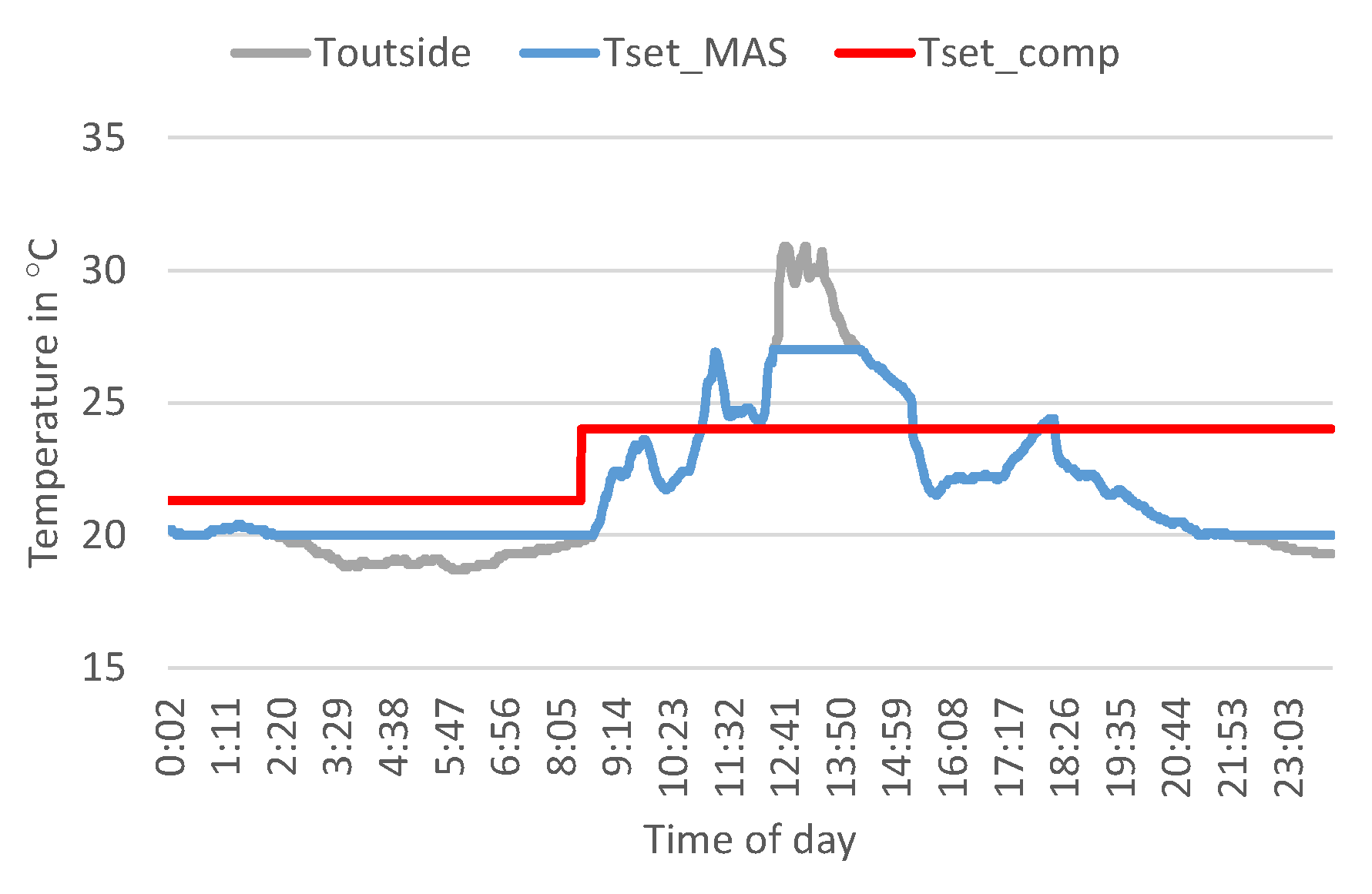
    As a qualitative measure, through the feedback from the comfort agent, which offers an array of information over room temperature, outside temperature, current productivity and comfort costs, as well as the responses from the room agent the occupant starts to think on the way he/she perceives personal comfort and how it is connected to other variables.

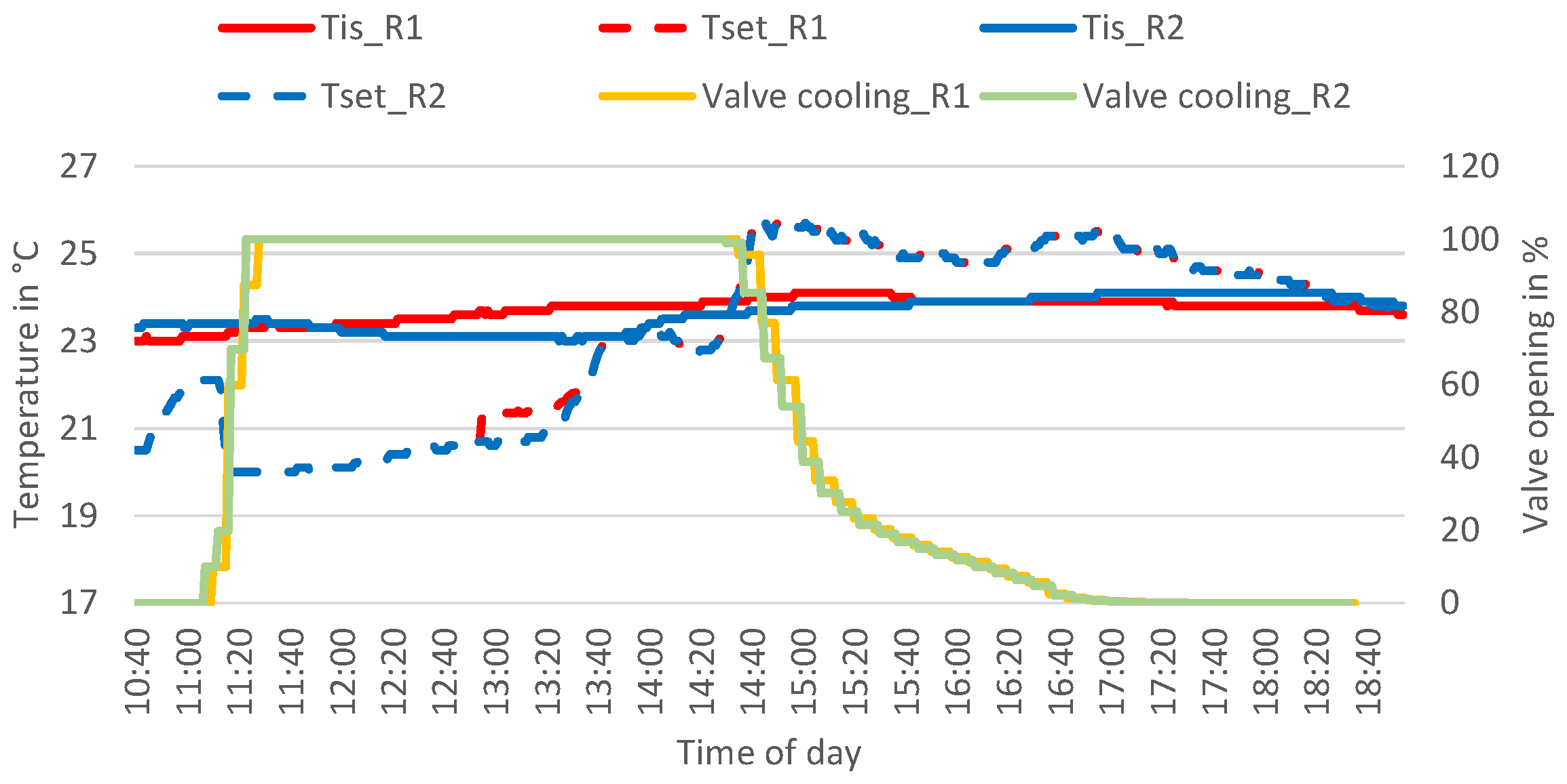
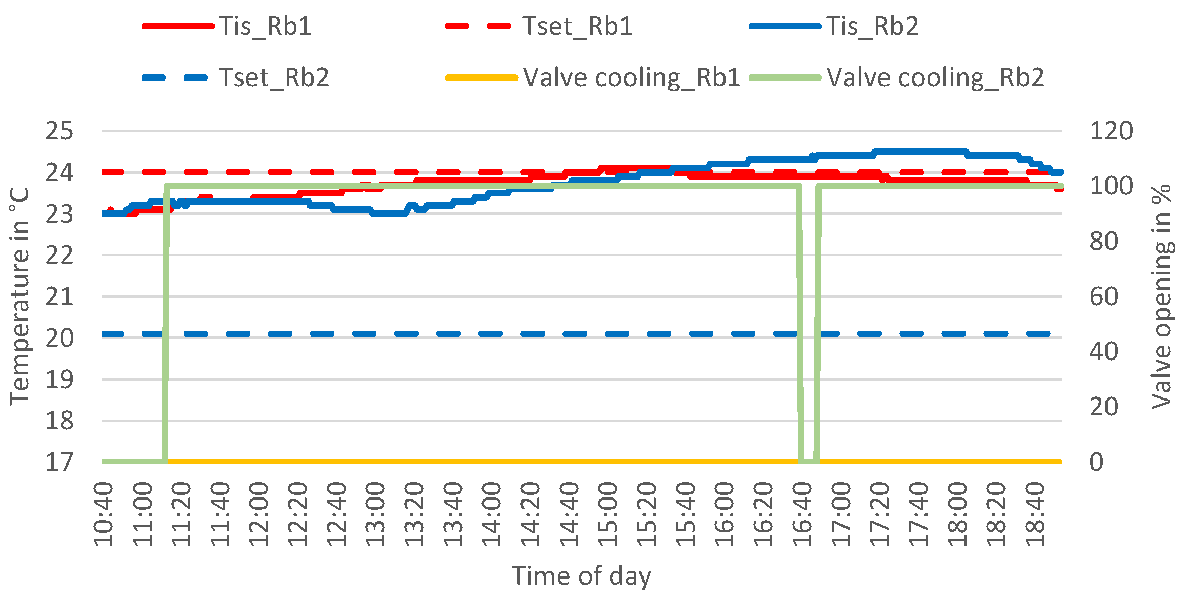
4.2. Simulation-Two Rooms Use Case

We used the simulation set-up for a two rooms (R1 and R2) use case described in Section 3.5. The users are present between 8 and 18 o’clock each day. The occupant in room R1 has an optimal set temperature of 20 C and the occupant in room R2 has an optimal set temperature of 19 C during the day. During the night, a night comfort agent with a set temperature of 18 C is present in both rooms. The tolerance band around the set temperature is ± 0.5 K , meaning as soon as the temperature goes outside these bounds a comfort violation occurs. The control strategy for this case is “optimize energy costs”.
For comparison of comfort and energy consumption we also simulate the benchmark case, with the temperature control done via thermostatic valve. For a given set temperature the thermostatic valve will aim to keep the room air temperature in an interval of 1 K above the set temperature. Outside these boundaries a comfort violation occurs. In order to have the same comfort intervals as in the MAS case, the set temperatures for the rooms are lowered to 19.5 C for room R1, 18.5 C for room R2 and 17.5 C during night time.
We present a simulation for a heating scenario, done over the first three days of January.
Expected results for MAS:
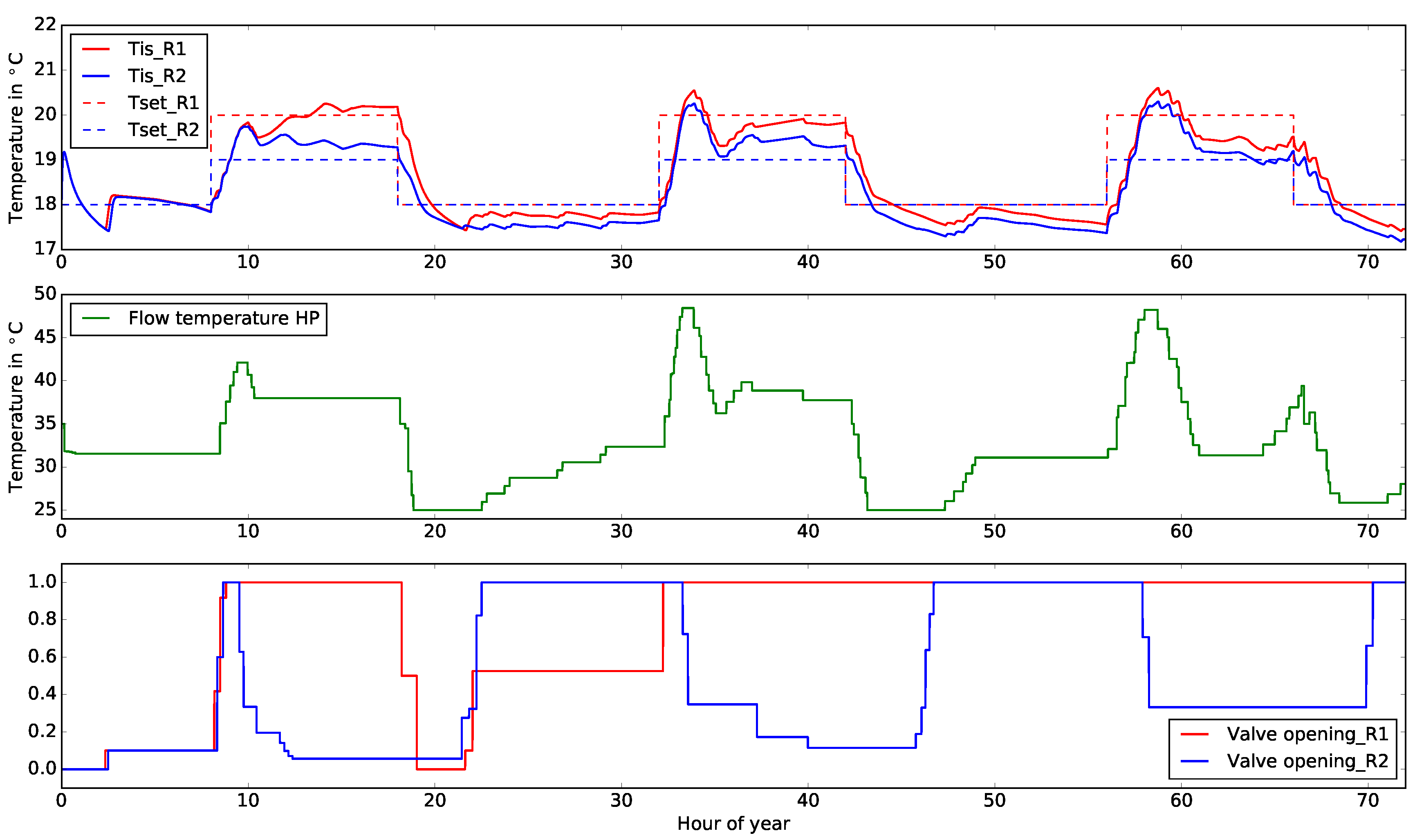
  • both room air temperatures stay in the tolerance interval around each set temperature
  • as the heat pump supplies both rooms and room R1 has a higher demand, during the hours the occupants are present, the valve opening in room R1 should be consistently higher than the one in room R2
  • the flow temperature of the heating pump should set on a mean value which is lower than the one given by a heating curve
Achieved results:
Figure 8 presents the air temperature, valve openings in each room and the flow temperature of the heating pump for the MAS system. .
The expected results happen, with the mention that the room air temperature in room R2 lies outside the tolerance interval more often than for room R1. This is mainly the case when the temperature in room R1, on account of the fully opened valve, can only be increased by increasing the supply temperature from the heat pump. This in return leads to more energy flowing automatically to room R2, although there is no need for that. So the valve in room R2 has to close, to reduce the volume flow and act against the heating trend of the heat pump. The room air temperature in room R2 is too high as long as the occupant needs come in conflict with the occupant needs of other room. This case can be prevented when integrating the comfort costs of the occupants in the control strategy, as the costs for the heat pump are higher than the comfort costs of just one occupant. Once the occupants’ preferences are complementary their aggregated comfort costs can be higher and lead to a change in the supply temperature to the room. In this way, through the feedback from the comfort agents occupants can also be educated on the costs of their preferences and maybe be persuaded to be more mindful of their energy consumption.
The mean flow temperature of the heat pump for the simulation period is 33.2 C, lower than the flow temperature according to the heating curve in the benchmark case, which is 40.7 C. This is in itself an advantage of the agent based system, as it does not require the setting up of a heating curve, but finds the correct supply temperature on its own, depending on the current requests of the rooms agents. Furthermore during the operation of a building’s energy system the heating curve might need to be adjusted manually by a professional. In our system, there is no need for this.
Table 3 presents key performance indicators for the two rooms, for both the agent based control and the benchmark cases. The following abbreviations are used: MAS-multi-agent system, BM-benchmark, Th-thermal and El-electrical. The lost comfort values for the MAS case are attributed mainly to the different set temperatures. The rooms sometimes have conflicting requests, which leads to the system in room R2 working to compensate the influence of room R1. Although the room air temperature fluctuates, the system is able to find an equilibrium.
When comparing against the benchmark system, we observe that the benchmark setup leads to higher thermal energy consumptions in the rooms (6% for each room), which translate into better comfort only for room R2. The overall energy savings with the MAS system are 9.5% compared to the benchmark case.
The results show that the concept of the agent system is viable and the behavior of the agents lead to the desired results according to the described use case. The next step in the testing of the system is the field test.

4.3. Field Test

Two runs of the field test were performed: one for heating scenarios and one for cooling scenarios. However the first set of tests proved challenging as the BACnet network in the building at that time was instable and would often crash making the communication between devices and agents over longer periods of time impossible. We assume this was in part because of additional experiments running in the building at the same time. This first field test allowed us to test the distribution of agents on the BBBs and the reading of the data points via BACnet. The second run of the field test proved more successful, as the BACnet network proved stable and longer experiments were possible. No additional experiments were running at that time in the building. For this experiments the agents ran on one machine.
During both runs of the field test, the response time of BACnet devices varied, from 0.01 s to 60 s. This variation was independent of the number of agents involved in the experiment, or whether or not the agents were distributed on the BBBs or running on one machine. Figure 9 presents the log for reading the relevant data points of the heat pump, with the value of the data point and the duration for reading the data point.
However, a response time of under a minute is adequate for our application, where new decisions have to be made every 15 minutes. The room agent has the most complex behavior. A CFP cycle triggered by a sub-optimal temperature and ending with sending an inform message to the comfort agent takes around three minutes and has eight different operations. Scaling up to multiple rooms, this duration should not increase as rooms do not communicate with each other, only with the energy supply agents, whose numbers (in our case) do not increase with the number of rooms. Energy supply agents are also capable of intelligent behavior, but when scaling up, the only additional decision they have to make is if the request for energy is complementary to the current trend or not (increase or decrease power). Future work will focus on whether or not an aggregation agent for the requests of the room agents when scaling up makes more sense than answering the requests of the room agents one by one.
As in the simulation tests, functionality tests ran and produced the expected results, meaning the agents identified correctly the needs of the room occupants and send the appropriate commands to the energy supply agents. This proved that the reading of the sensor values and the writing of the set points worked correctly, since the behavior of the agents had already been tested in the simulation.
Figure 10 presents a cooling experiment over six hours, for the two rooms (R1 and R2) where the system was tested. ‘Tis’ is the current room temperature and ‘Tset’ the set temperature. The set temperatures have the same dynamic profile as in Figure 5, because they use the same type of function. The only difference between the set temperatures is observed around 13:00, when a second user arrives in room R1 and has a different preferred set temperature than the others. The start state of the experiment is with the cooling valves fully closed for both rooms. The room agents monitor the room temperatures against the set temperatures and start CFPs for cooling the rooms. At the time of the experiments the heat pump was not active, cooling power being provided by a geothermal field, only the circulation pumps of both the heating and the cooling circuits were involved in the CFP. The cooling valves react by gradually opening fully. When later in the day the set temperature becomes higher than the room temperature (as the outside temperature rises), the cooling valve closes. The heating vales do not open in this case, as the outside temperature is above the heating limit of 20 C.
The main challenge of the field test lies in the ability of the technical equipment to achieve the set temperature. As shown in Figure 10 the room temperature reacts very little to the changes in the valve setting in both rooms. While the facade ventilation unit does supply the room with additional thermal energy for cooling, the process does not lead to a change in the measured value. The reason for this being that the air mixing in the room is imperfect, with pieces of furniture often in the way of the supplied air stream. Additionally, the room air temperature sensor is placed on the wall opposing the facade ventilation unit.
This type of behavior from the technical equipment makes a comparison between the MAS system and the benchmark using the introduced KPI difficult. While the system behaves as expected, the resulted room air temperature in each of the field test offices (for the MAS and benchmark both) do not reflect the different control strategies.
Figure 11 presents the room and set temperatures, as well as valve openings for two different rooms in the building, over the same period of time and with the same starting conditions as the MAS experiment. Rb1 is the benchmark room presented in Figure 6, while Rb2 is a room with the same usage and orientation, but no additional measuring equipment installed. We chose to present the results for Rb2, as they stand in stark contrast to Rb1. While the users in Rb1 have a set temperature of 20 C, the ones in Rb2 have a set temperature of 24 C. As such the cooling valve in Rb1 is permanently opened, while the one in Rb2 is permanently closed. The short period when the valve closes in Rb1 is because of a window opening, when the facade ventilation unit turns off. The actual room temperatures however have very similar profiles.
An additional set of use cases was tested in the field test, which weren’t possible or relevant on a simulation base: the Plug-and-Play use cases. We consider two cases relevant for the plug-in of a component:
  • Completely new component: a new component is introduced in the system, be it a sensor, a valve or a pump
  • Replacement of an existing component: an old component is replaced by a new component.
When adding or replacing a component, the data model for that component has to be filled in or updated. As our system configures the platform at start time using an initialization file (agents.ini), the introduction of new components means a new start of the platform. However, this does not greatly influence the system, as only the very recent history (last 15 minutes) is relevant, and only for the calculation of the thermal capacity of the room model. Possible future work could focus on setting up or connecting to a database where measured and metered values can be stored, so that at the start, the system has full knowledge of the current situation. Additionally, a cyclic routine can be written to periodically check if the configuration file has been extended, in this way eliminating the need to restart the platform.

5. Conclusions and Outlook

The goal of this work was to develop methodologically a MAS for energy and comfort management in non-residential buildings. We started from an ontology and by focusing on the application on non-residential buildings added a data model. Further pursuing our validation and demonstration options we developed use cases for the different system functionalities, mainly normal operation and plug-in of a new component. Operatively, the agents can take on different control strategies. The methodology allows for easy extension or re-use of the system for new use cases for non-residential buildings.
For the preliminary validation and fine tuning of the MAS, we ran simulation tests were the agents, programmed in JADE, communicate via TCP/IP with simulation models of devices, coupled with a simulation model of the building, using Dymola/Modelica. The simulation results show that a multi-agent system is able to satisfy the comfort requirements of different rooms, while aiming for energy efficiency. When looking at a heating scenario with two rooms, we see that if the rooms have different requests (less vs. more thermal energy) from the same energy supply agent, the MAS is able to find an equilibrium solution, but until this state is reached the conditions in one of the rooms can go outside the comfort corridor. A dampening of this effect could be achieved when considering the comfort costs of the room occupants. When compared to a benchmark setup using commonly used control strategies for the technical equipment involved, the MAS system leads to a more energy efficient behavior, with the added bonus of the building energy system finding on its own appropriate set values depending on the current energy demand in the system, without the need of presetting values.
A field test was set up, for testing both one and two rooms use cases with agents deployed on BeagleBones Black and communicating with the devices in the building via BACnet. As the data models are derived from manufacturer data, the transfer from simulation to field test is unproblematic regarding the data exchanged between agents and the attached devices. Functionality tests were carried out successfully for the system. The main challenge of the field test lies in the ability of the technical equipment to achieve the given set temperature. This highlights the challenge of testing a concept in simulation and in field test. Because while a simulation experiment is straight forward to evaluate, including comparison with a benchmark, a field test presents different uncertainties (user behavior, capacity of the installed equipment, adequate placement of sensors) which make quantitative evaluations difficult.
The response time of the devices over BACnet can vary up to two degrees of magnitude (0.01 s–60 s). However, the response times are acceptable for the dynamics of the system. Adding additional comfort agents, sensors or energy supply agents to the system is possible, by adding or updating the filled in data model for the component. A GUI for the room occupants was developed for the field test, and it allows the user to directly input comfort preferences and also receive information from the system regarding if and how these preferences can be satisfied. We believe this type of feedback can sensitize the user towards a more energy-efficient behavior.
Further work will focus on scaling up the system and going to more than two rooms, meaning more than two room agents that send CFPs. In this case an aggregation agent for the CFPs for the energy supply agents is an interesting possibility, to allow energy supply agents to address different requests simultaneously.

Acknowledgments

The authors would like to thank the E.ON gGmbH for the financial support.

Author Contributions

Ana Constantin, Artur Löwen, Ferdinanda Ponci, Dirk Müller and Antonello Monti developed the concept of the multi-agent system; Ana Constantin developed the ontology, data models, simulation models, setup the field test, did the experiments and analyzed the results; Artur Löwen implemented the agents in JADE and deployed them on the BBBs; Ana Constantin wrote the paper, with feedback from Ferdinanda Ponci.

Conflicts of Interest

The authors declare no conflict of interest.

References

  1. International Energy Agency. Building Energy Performance Metrics: Supporting Energy Efficiency Progress in Major Economies; Technical report; IEA: Paris, France, 2015. [Google Scholar]
  2. International Energy Agency. Energy Technology Perspectives 2015; Technical report; IEA: Paris, France, 2015. [Google Scholar]
  3. Shaikh, P.H.; Nor, N.B.M.; Nallagownden, P.; Elamvazuthi, I.; Ibrahim, T. A review on optimized control systems for building energy and comfort management of smart sustainable buildings. Renew. Sustain. Energy Rev. 2014, 34, 409–429. [Google Scholar] [CrossRef]
  4. Labeodan, T.; Aduda, K.; Boxem, G.; Zeiler, W. On the application of multi-agent systems in buildings for improved building operations, performance and smart grid interaction A survey. Renew. Sustain. Energy Rev. 2015, 50, 1405–1414. [Google Scholar] [CrossRef]
  5. Russell, S.J.; Norvig, P. Artificial Intelligence A Modern Approach; Prentice Hall/Pearson Education, 2003. [Google Scholar]
  6. Constantin, A.; Ponci, F.; Löwen, A.; Isermann, T.; Müller, D. Agent-Based Control for Non-Residential Buildings; E.ON Energy Research Center: Aachen, Germany, 2016; Volume 8, p. 74. [Google Scholar]
  7. Kok, K.; Warmer, C.; Kamphuis, R. PowerMatcher: multiagent control in the electricity infrastructure. In Proceedings of the 4th International Joint conference on Autonomous Agents and Multiagent Systems, Utrecht, Netherlands, 25–29 July 2005; industry track. pp. 75–82. [Google Scholar]
  8. Gruber, T.R. A translation approach to portable ontology specifications. Knowl. Acquis. 1993, 5, 199–220. [Google Scholar] [CrossRef]
  9. Spyns, P.; Meersman, R.; Jarrar, M. Data modelling versus ontology engineering. ACM SIGMOD Rec. 2002, 31, 12. [Google Scholar] [CrossRef]
  10. Noy, N.F.; McGuiness, D.L. Ontology Development 101: A Guide to Creating Your First Ontology: Stanford Knowledge Systems Laboratory Technical Report KSL-01-05 and Stanford Medical Informatics; Technical Report SMI-2001-0880; Stanford University: Stanford, CA, USA, 2001. [Google Scholar]
  11. Musen, M.A. The Protégé project: a look back and a look forward. Artificial Intelligence 2015, 1, 4–12. [Google Scholar] [CrossRef] [PubMed]
  12. van Dam, K.H. Capturing Socio-Technical Systems with Agent-Based Modelling. PhD Thesis, Delft University of Technology, Delft, Netherlands, Next Generation Infrastructures Foundation. 30 October 2009. [Google Scholar]
  13. Dibley, M.; Li, H.; Rezgui, Y.; Miles, J. An ontology framework for intelligent sensor-based building monitoring. Autom. Constr. 2012, 28, 1–14. [Google Scholar] [CrossRef]
  14. Smart Grid Coordination Group. Smart Grid Reference Architecture; Technical report; Smart Grid Coordination Group: Bruxelles, Belgium, 2012. [Google Scholar]
  15. Foundation for Intelligent Physical Agents. Device Ontology Specification, SC00091E; Foundation for Intelligent Physical Agents: Geneva, Switzerland, 2002. [Google Scholar]
  16. Foundation for Intelligent Physical Agents. Communicative Act Libary Specification SC00037J; Foundation for Intelligent Physical Agents: Geneva, Switzerland, 2002. [Google Scholar]
  17. Grimshaw, D. JADE Administration Tutorial; Ryerson University: Toronto, ON, Canada, 2010. [Google Scholar]
  18. Corrado, V.; Ballarini, I.; Madrazo, L.; Nemirovskij, G. Data structuring for the ontological modelling of urban energy systems: The experience of the SEMANCO project. Sustain. Cities Soc. 2015, 14, 223–235. [Google Scholar] [CrossRef]
  19. International Electrotechnical Commission. Communication Networks and Systems for Power Utility Automation Part 7-4: Basic Communication Structure-Compatible Logical Node Classes and Data Object Classes, IEC EN 61850-7-4; Number IEC EN 61850-7-4; International Electrotechnical Commission: Geneva, Switzerland, 2010. [Google Scholar]
  20. International Organization for Standardization. Industry Foundation Classes (IFC) for Data Sharing in the Construction and Facility Management Industries, ISO 16739:2013; Number ISO 16739; International Organization fo Standardization: Geneva, Switzerland, 2013. [Google Scholar]
  21. Smart Grid Coordination Group. Use Case Collection, Management, Repository, Analysis and Harmonization; Draft report; Smart Grid Coordination Group Sustainable Processes: Bruxelles, Belgium, 2012. [Google Scholar]
  22. International Electrotechnical Commission. Intelligrid Methodology for Developing Requirements for Energy Systems; Number IEC/PAS 62559; International Electrotechnical Commission: Geneva, Switzerland, 2008. [Google Scholar]
  23. Fütterer, J.; Constantin, A.; Müller, D. An energy concept for multifunctional buildings with geothermal energy and photovoltaic. Proceedings of CISBAT 2011: Cleantech for sustainable buildings from nano to urban scale, Lausanne, Switzerland, 14–16 September 2011; Volume 1–2. [Google Scholar]
  24. Seppaenen, O.; Fisk, W.; Lei, Q. Effect of Temperature on Task Performance in Offfice Environment; Technical report; Orlando Lawrence Berkley National Laboraory: Berkeley, CA, USA, 2006. [Google Scholar]
  25. American Society of Heating, Refrigerating and Air-Conditioning Engineers. BACnet: A Data Communication Protocol for Building Automation and Control Networks; Number ASHRAE 135; American Society of Heating, Refrigerating and Air-Conditioning Engineers: New York, NY, USA, 2016. [Google Scholar]
  26. Constantin, A.; Löwen, A.; Ponci, F.; Huchtemann, K.; Müller, D. Dymola-JADE Co-Simulation for Agent-Based Control in Office Spaces. In Proceedings of the 12th International Modelica Conference, Prague, Czech Republic, 15–17 May 2017. [Google Scholar]
Figure 1. Main classes of the ontology, with detail on the agent class.
Energies 10 01106 g001
Figure 2. Agents involved in a two room use case.
Energies 10 01106 g002
Figure 3. Normalized performance against room air temperature, adapted from [24].
Energies 10 01106 g003
Figure 4. Screen shot of the user GUI detailing the calculation of set temperature as a function of outside temperature.
Energies 10 01106 g004
Figure 5. Set temperatures for user in MAS controlled and a comparison office.
Energies 10 01106 g005
Figure 6. Rooms for field test validation, marked with a blue frame.
Energies 10 01106 g006
Figure 7. User interface and box with air temperature sensor.
Energies 10 01106 g007
Figure 8. Air temperature, flow temperature to the room and valve opening for room 1 (R1) and room 2 (R2) in a heating experiment.
Energies 10 01106 g008
Figure 9. Part of log file on reading the heat pump data points over BACnet.
Energies 10 01106 g009
Figure 10. Room and set temperatures and valve openings for two MAS rooms in the field test.
Energies 10 01106 g010
Figure 11. Room and set temperatures, and valve openings for two benchmark rooms in the field test.
Energies 10 01106 g011
Table 1. Part of the data model for a heat pump.
NameTypeExampleDescription
Measured and metered values
Energy data
T_Co_inreal293.15in K, temperature into condenser
T_Co_outreal300.15in K, temperature out of condenser
T_Ev_inreal283.15in K, temperature into evaporator
T_Ev_outreal273.15in K, temperature out of evaporator
nreal300in 1/min, rotational speed
Pel_nowreal10000in W, current electrical power
QflowUse_nowreal20000in W, current thermal power
REDKlist[R1, 0.2]list with room energy distribution keys
Pel_Pos_maxreal3000in W, maximum additional supplied power
Energy cost data
relevantCostreal150.0in W, electrical power to provide needed thermal power
Table 2. Deployment on BBB.
BBB No.Agents
BBB1Comfort agents for all rooms (4)
BBB2Room agent Room 1
BBB3Room agent Room 2
BBB4Energy supply agent pump heating
BBB5Energy supply agent pump cooling
BBB6Energy supply agent heat pump
BBB7Electricity info agent
BBB8All sensors (17)
BBB9All actuators (4)
Table 3. KPI two rooms use case.
ComponentKPIUnitValue MASValue BM
Room 1Th. energykWh18.719.9
Room 2Th. energykWh1819.1
Room 1Lost comfort K · h 3.16.2
Room 2Lost comfort K · h 8.53
PumpEl. energy K · h 0.450.23
Heat pumpEl. energy K · h 112124

