A Novel Sectionalizing Method for Power System Parallel Restoration Based on Minimum Spanning Tree


Abstract
:1. Introduction
- (1)
- The start-up time of generating units and the restoration time of branches are considered in the problem formulation, which help minimize the SRT.
- (2)
- By employing the dispatchable loads as an important constraint, it ensures that generating units are restored safely.
- (3)
- Candidate boundary lines of a system are identified according to the skeleton network and used to generate candidate sectionalizing schemes. Expansion in system size will not significantly increase the complexity of the proposed method.
- (4)
- It can be applied to power systems under various conditions, including the conditions when some components are not available, and provide multiple schemes for dispatchers.
2. Problem Formulation
2.1. Objective
2.2. Constraints
2.2.1. Constraint on the Number of Subsystems
2.2.2. Minimum Output Constraint on Generating Units
2.2.3. Capacity Constraint on Generating Units
2.2.4. Constraint on Faulted Devices
3. The Proposed Method for Sectionalizing
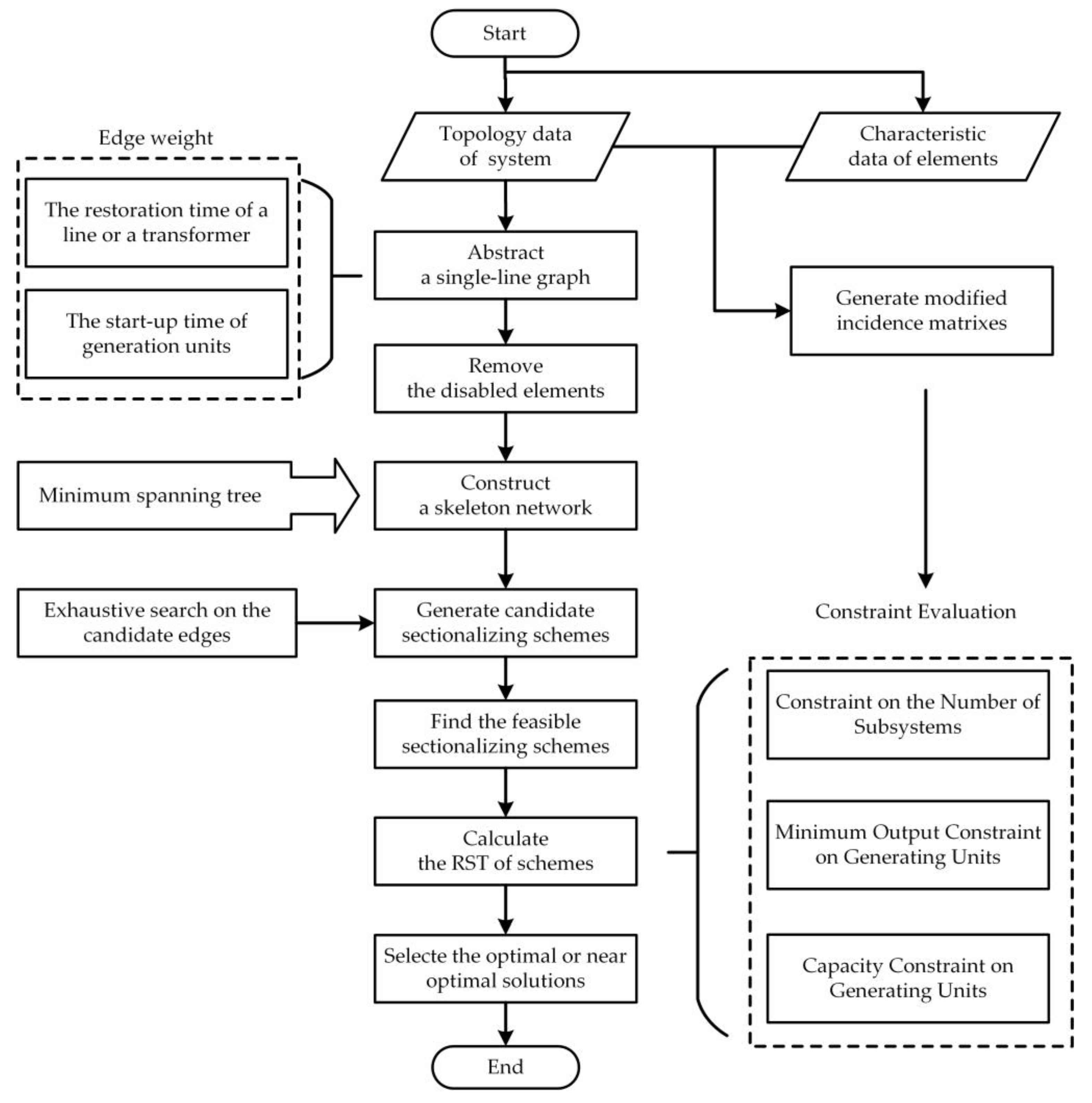
3.1. Procedure of the Proposed Sectionalizing Method
3.2. Constructing the Skeleton Network Based on Minimum Spanning Tree
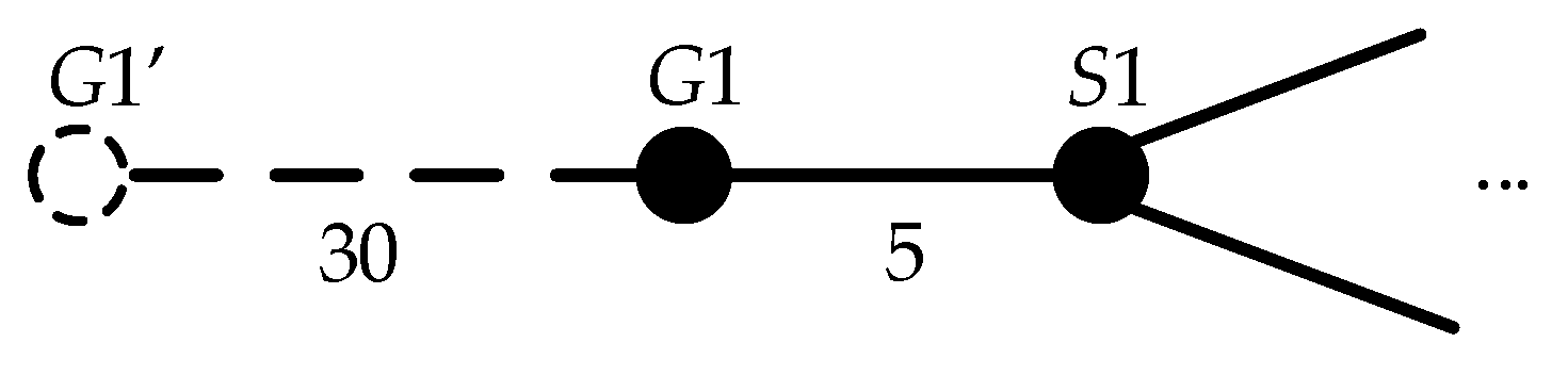
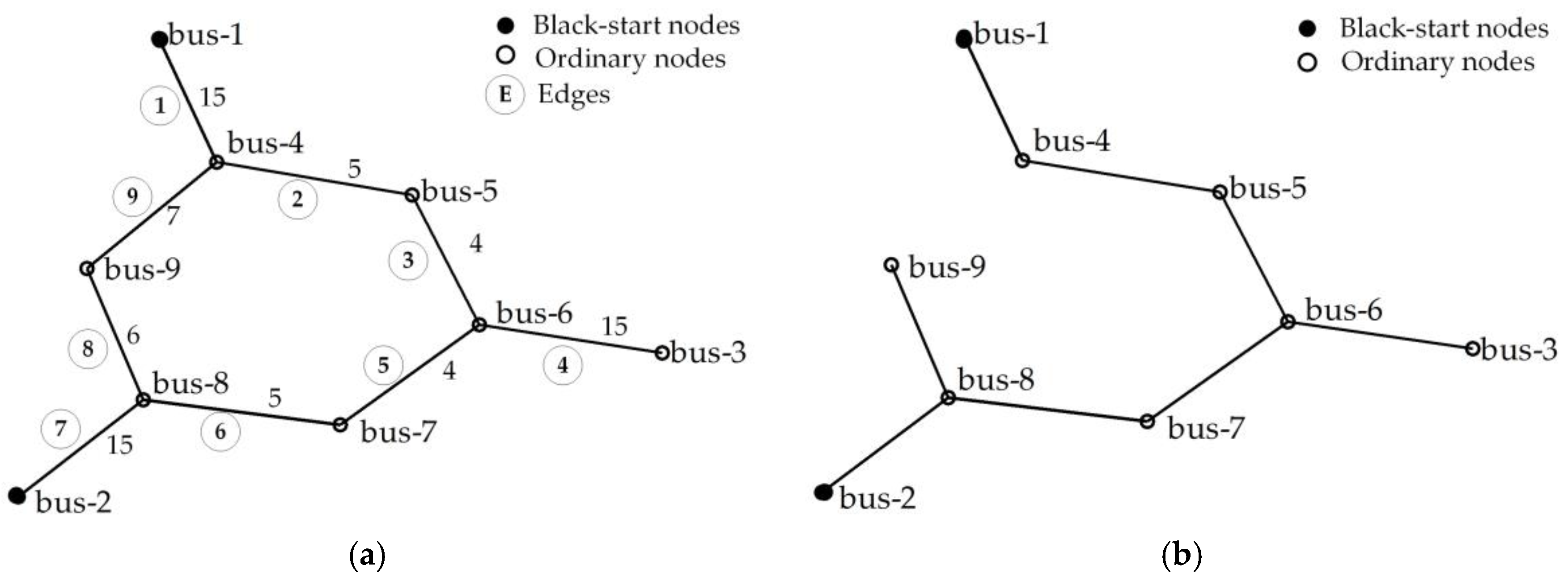
3.2.1. Abstraction of a Power System
3.2.2. The skeleton network Based on Minimum Spanning Tree
3.3. Candidate Sectionalizing Schemes Generation
3.4. Constraint Evaluation
3.4.1. Constraint on the Number of Subsystems
3.4.2. Minimum Output Constraint on Generating Units
3.4.3. Capacity Constraint on Generating Units
3.5. Optimal Sectionalizing Schemes
4. Case Studies
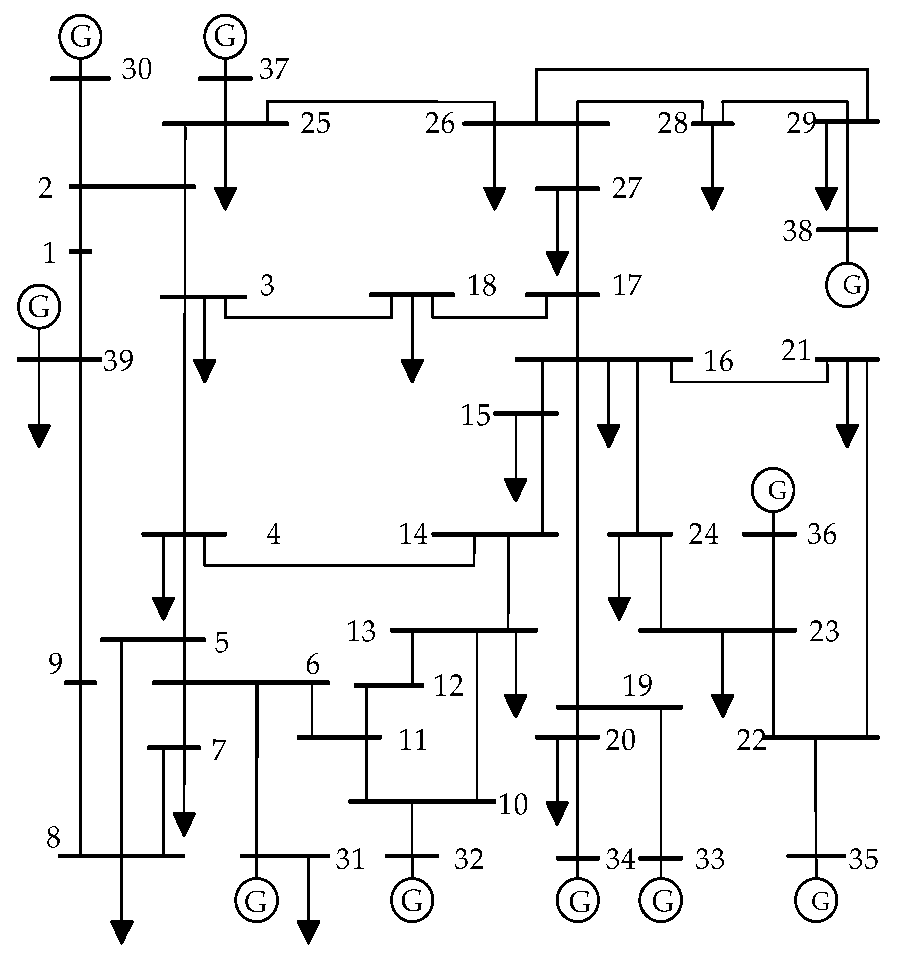
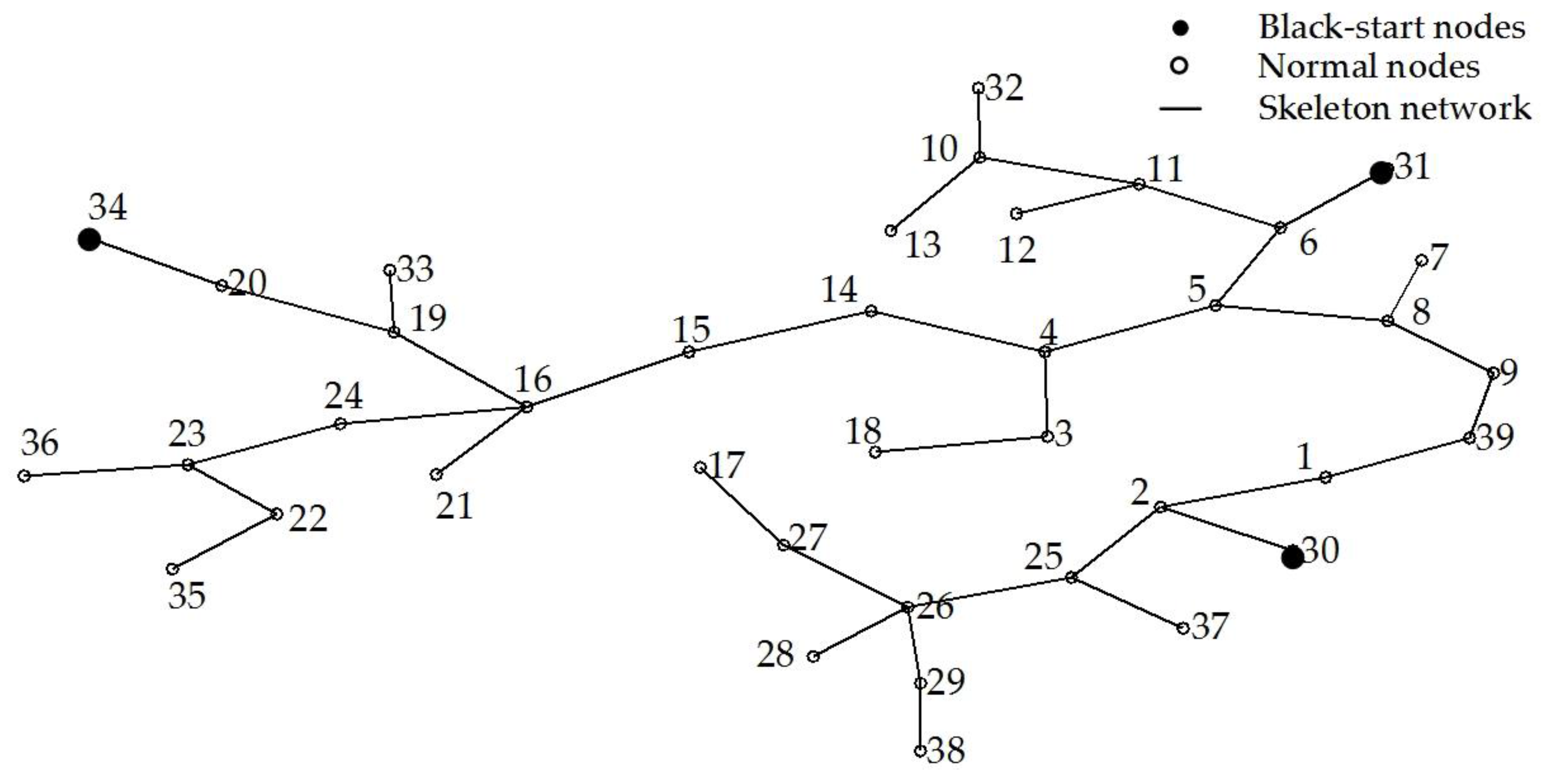
4.1. IEEE 39-Bus Test System
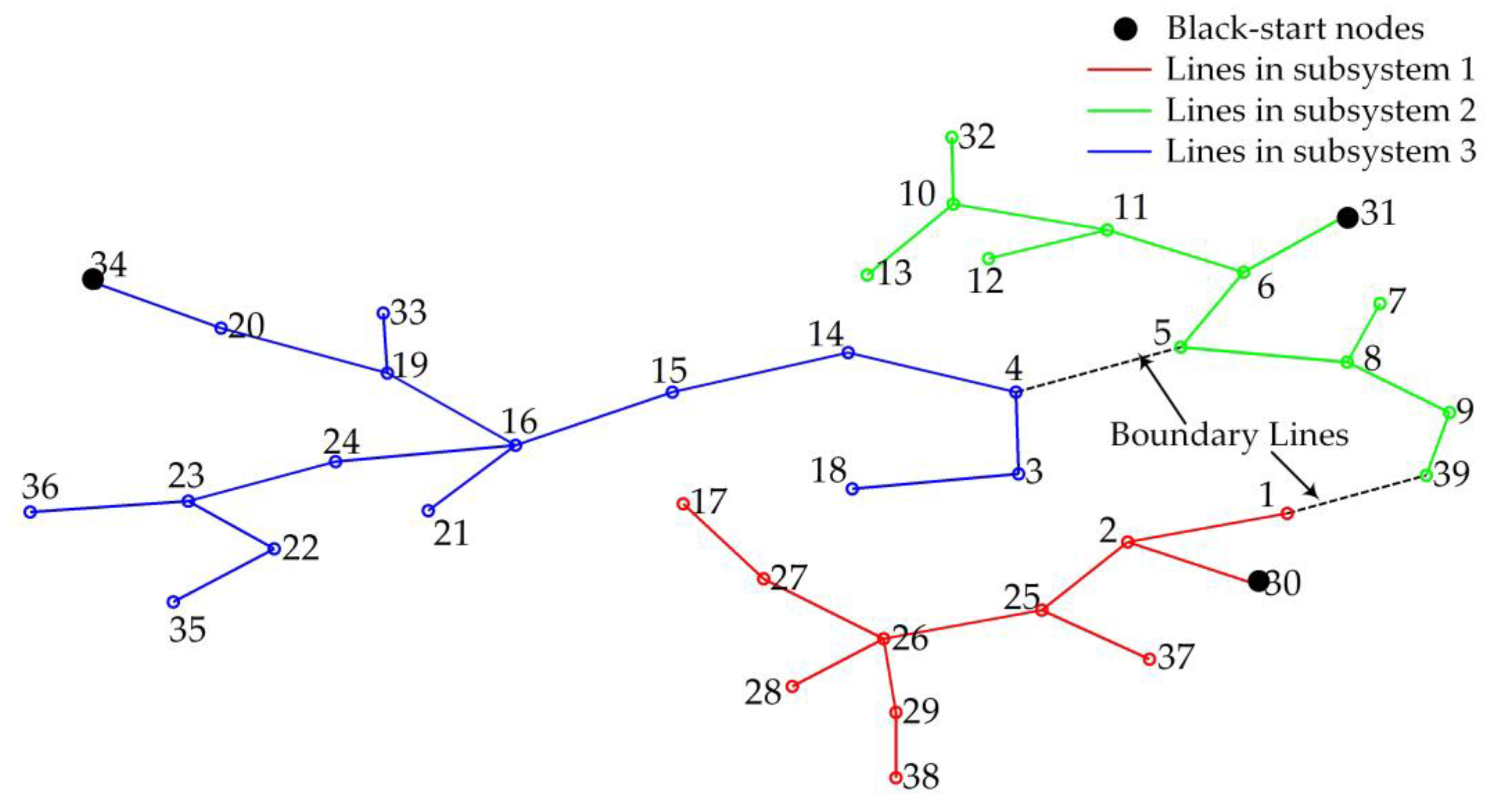
4.1.1. Construct the Skeleton Network Based on MST
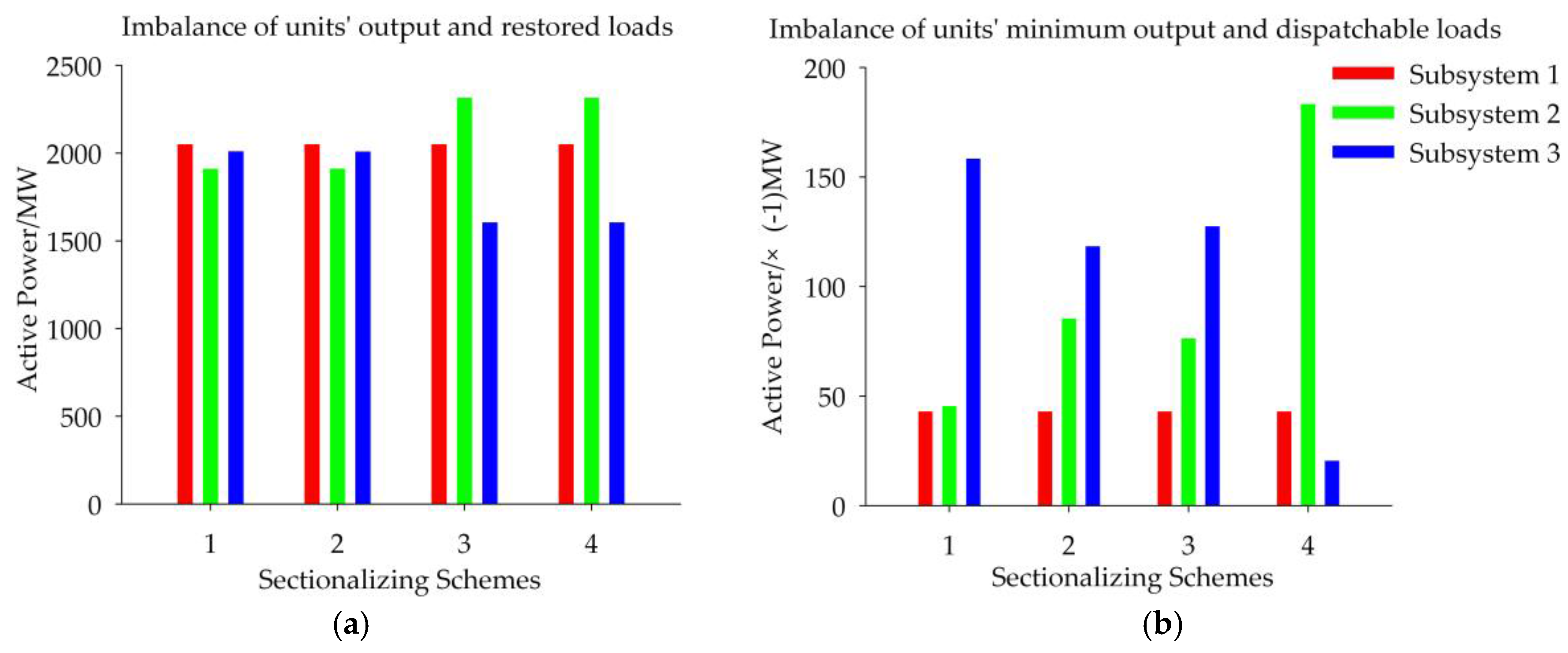
4.1.2. Generate Candidate Schemes
4.1.3. Evaluate Constraints
4.1.4. Determine the Optimal Sectionalizing Scheme
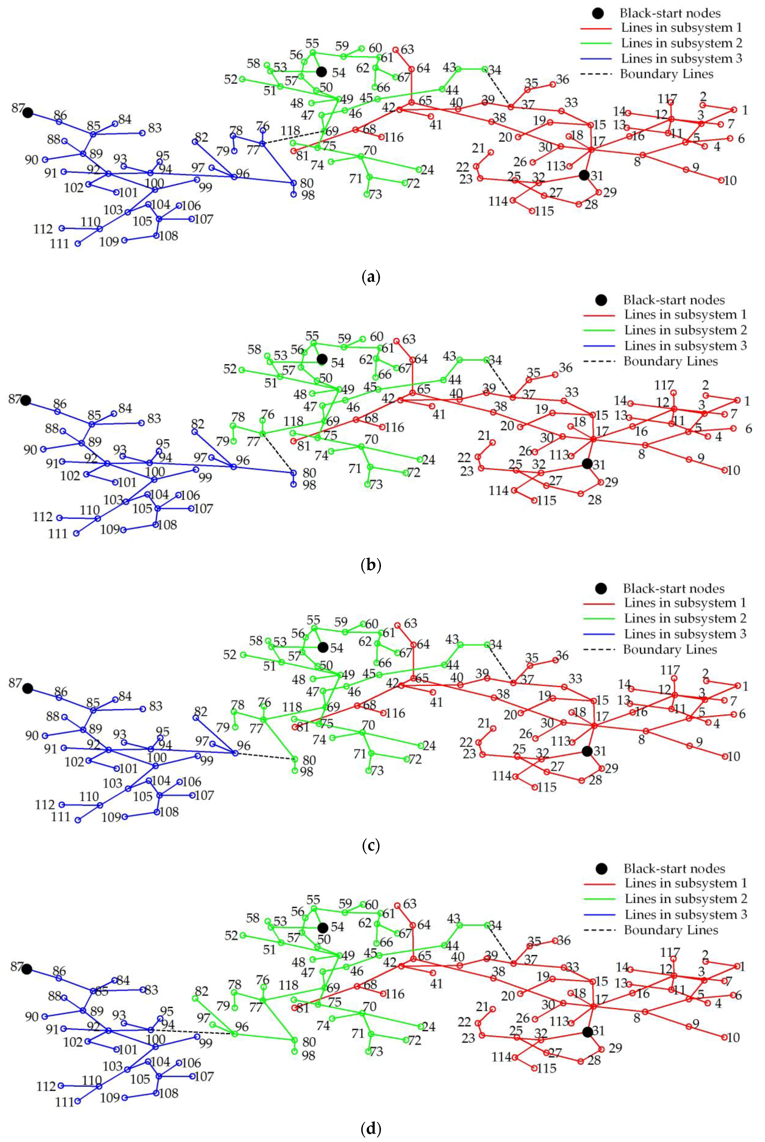
4.2. IEEE 118-Bus Test System
4.2.1. Scenario 1: All Devices Are Available for Restoration
4.2.2. Scenario 2: Sectionalizing with Unavailable Devices
- The non-black-start unit at bus 72;
- The line 34–37; and
- The loads at buses 1 and 2.
4.3. Discussions
4.3.1. About the Objective Function
4.3.2. Remarks on Computational Time
- The first step, i.e., constructing the skeleton network, consumes 0.259 s.
- The second step, i.e., generating candidate sectionalizing schemes, consumes 0.157 s.
- The third step, i.e., evaluating constraints, consumes 8.142 min. Parallel computation techniques can be used to reduce the computational time of this step.
- The last step, i.e., selecting optimal or near optimal schemes, consumes 0.02 s.
4.3.3. Hybrid Renewable Energy System for Restoration
5. Conclusions
- (1)
- The proposed method seeks to minimize the SRT, which helps balance the restoration time of subsystems. It can provide multiple schemes so that dispatchers can choose one for application according to actual requirement.
- (2)
- The proposed method is based on the MST. It identifies the candidate boundary lines according to the skeleton network. It can reduce the search space for solution and shorten the computational time for large-scale power systems.
- (3)
- The SRT depends on the start-up time of generating units and the restoration time of branches. In particular, the start-up time of generating units is an important factor for sectionalization. Therefore, it cannot be ignored for the estimating the restoration time.
- (4)
- The proposed method is suitable for power systems under various conditions, including the conditions when some components are damaged. The case study results indicate that faulted devices may have negative effects on the SRT.
Acknowledgments
Author Contributions
Conflicts of Interest
Nomenclature
| graph representing a power system | |
| minimum spanning tree, i.e., skeleton network | |
| set of nodes in graph G | |
| set of edges in graph G | |
| set of edges in skeleton network T | |
| total weight of edges | |
| number of subsystems | |
| index of subsystems | |
| restoration time of subsystem | |
| number of nodes in a power system | |
| number of nodes in subsystem | |
| number of black-start generating units | |
| index of nodes | |
| number of edges in a power system | |
| index of edges in a power system | |
| weight of edge in a power system | |
| number of edges in the skeleton network | |
| index of edges in the skeleton network | |
| weight of edge in the skeleton network | |
| decision variable of edge in the skeleton network. If edge belongs to subsystem , ; otherwise, | |
| number of candidate edges for boundary lines | |
| total active power capacity of the generating units at bus in subsystem | |
| total minimum output of the generating units at bus in subsystem | |
| imbalance of generating units’ minimum output and dispatchable loads at bus | |
| imbalance of generating units’ output and critical loads at bus | |
| total active power demand of the critical loads at bus in subsystem | |
| total active power demand of the dispatchable loads at bus in subsystem | |
| set of faulted devices | |
| set of devices available for restoration | |
| black-start incidence matrix | |
| -element of . If an available black-start unit locates at node which is one terminal of edge , the ; otherwise, | |
| black-start judgment matrix for the constraint on the number of subsystems | |
| black-start indicator index for subsystem | |
| number of available black-start generating units in subsystem | |
| minimum output incidence matrix | |
| -element of . If edge connects a generating unit or a dispatchable load located at bus , the ; otherwise, | |
| minimum output judgment matrix for the minimum output constraint on generating units | |
| imbalance of generating units’ minimum output and dispatchable loads in subsystem | |
| capacity incidence matrix | |
| -element of . If edge connects a generating unit or a critical load located at bus , the ; otherwise, | |
| capacity judgment matrix for the capacity constraint on generating units | |
| imbalance of generating units’ output and restored loads in subsystem | |
| MST | minimum spanning tree |
| SRT | the system restoration time |
| CE | the candidate edge |
| IMODL | the imbalance of generating units’ minimum output and dispatchable loads |
| IOCL | the imbalance of units’ output and critical loads |
| IORL | the imbalance of generating units’ output and restored loads |
References
- Andersson, G.; Donalek, P.; Farmer, R.; Hatziargyriou, N. Causes of the 2003 major grid blackouts in north america and europe, and recommended means to improve system dynamic performance. IEEE Trans. Power Syst. 2005, 20, 1922–1928. [Google Scholar] [CrossRef]
- Li, C.; Sun, Y.; Chen, X. Analysis of the blackout in Europe on 4 November 2006. In Proceedings of the 2007 International Power Engineering Conference, Singapore, Singapore, 3–6 December 2007; pp. 939–944. [Google Scholar]
- Ministry of Indian Power. Report of the Enquiry Committee on Grid Disturbance in Northern Region on 30th July 2012 and in Northern, Eastern & North-Eastern Region on 31st July 2012; Enquiry Committee of Ministry of Indian Power: New Delhi, India, 2012.
- Project Group Turkey. Report on Blackout in Turkey on 31st March 2015; TEIAS and ENTSO-E: Brussels, Belgium, 2015. [Google Scholar]
- Mehdi, G.; Neng, F.; Jianhui, W. Two-stage stochastic optimal islanding operations under severe multiple contingencies in power grids. Electr. Power Syst. Res. 2014, 114, 68–77. [Google Scholar]
- Sarwat, A.I.; Amini, M.; Domijan, A.; Damnjanovic, A.; Kaleem, F. Weather-based interruption prediction in the smart grid utilizing chronological data. J. Mod. Power Syst. Clean Energy 2016, 5, 308–315. [Google Scholar] [CrossRef]
- Boroojeni, K.G.; Amini, M.H.; Iyengar, S.S. Smart Grids: Security and Privacy Issues; Springer: Cham, Switzerland, 2017. [Google Scholar]
- Sarwat, A.I.; Domijan, A.; Amini, M.H.; Damnjanovic, A.; Moghadasi, A. Smart Grid reliability assessment utilizing Boolean Driven Markov Process and variable weather conditions. In Proceedings of the 2015 North American Power Symposium (NAPS), Charlotte, NC, USA, 4–6 October 2015. [Google Scholar]
- Golari, M.; Fan, N.; Wang, J. Large-scale stochastic power grid islanding operations by line switching and controlled load shedding. Energy Syst. 2016, 7, 1–21. [Google Scholar] [CrossRef]
- Liu, Y.T.; Fan, R.; Terzija, V. Power system restoration: a literature review from 2006 to 2016. J. Mod. Power Syst. Clean Energy 2016, 4, 1–10. [Google Scholar] [CrossRef]
- Pesoti, P.M.; Lorenci, E.D.; Souza, A.Z.D.; Lo, K.; Lopes, B.L. Robustness area technique developing guidelines for power system restoration. Energies 2017, 10, 99. [Google Scholar] [CrossRef]
- Adibi, M.; Clelland, P.; Fink, L.; Happ, H. Power system restoration—A task force report. IEEE Trans. Power Syst. 1987, 2, 271–277. [Google Scholar] [CrossRef]
- Fink, L.H.; Liou, K.L.; Liu, C.C. From generic restoration actions to specific restoration strategies. IEEE Trans. Power Syst. 1995, 10, 745–752. [Google Scholar] [CrossRef]
- Sun, W.; Liu, C.C.; Zhang, L. Optimal generator start-up strategy for bulk power system restoration. IEEE Trans. Power Syst. 2011, 26, 1357–1366. [Google Scholar] [CrossRef]
- Zhang, C.; Lin, Z.; Wen, F.; Ledwich, G. Two-stage power network reconfiguration strategy considering node importance and restored generation capacity. IET Gener. Trans. Distrib. 2014, 8, 91–103. [Google Scholar] [CrossRef]
- Liu, W.; Lin, Z.; Wen, F.; Ledwich, G. A wide area monitoring system based load restoration method. IEEE Trans. Power Syst. 2013, 28, 2025–2034. [Google Scholar] [CrossRef]
- System Operations Division. PJM Manual 36: System Restoration; PJM: Audubon, PA, USA, 2010. [Google Scholar]
- National Grid Electricity Transmission. The Grid Code; National Grid Electricity Transmission: Warwick, UK, 2016.
- Chen, T.; Feng, L.; Liu, X.; Zhang, L. Comparison study on restoration strategies of Chongqing power grid. In Proceedings of the 5th International Conference on Electric Utility Deregulation and Restructuring and Power Technologies, Changsha, China, 26–29 November 2015; pp. 2425–2430. [Google Scholar]
- Wang, C.; Vittal, V.; Sun, K. OBDD-based sectionalizing strategies for parallel power system restoration. IEEE Trans. Power Syst. 2011, 26, 1426–1433. [Google Scholar] [CrossRef]
- Afrakhte, H.; Haghifam, M.R. Optimal islands determination in power system restoration. Iran. J. Sci. Technol. Trans. B Eng. 2009, 33, 463–476. [Google Scholar]
- Liang, H.P.; Gu, X.P.; Zhao, D. Optimization of system partitioning schemes for power system black-start restoration based on genetic algorithms. In Proceedings of the 2010 Asia-Pacific Power and Energy Engineering Conference, Chengdu, China, 28–31 March 2010; pp. 1–4. [Google Scholar]
- Quirós-Tortós, J.; Panteli, M.; Wall, P.; Terzija, V. Sectionalising methodology for parallel system restoration based on graph theory. IET Gener. Trans. Distrib. 2015, 9, 1216–1225. [Google Scholar]
- Sun, L.; Zhang, C.; Lin, Z.; Wen, F. Network partitioning strategy for parallel power system restoration. IET Gener. Trans. Distrib. 2016, 10, 1883–1892. [Google Scholar] [CrossRef]
- Sarmadi, S.A.N.; Dobakhshari, A.S.; Azizi, S.; Ranjbar, A.M. A sectionalizing method in power system restoration based on WAMS. IEEE Trans. Smart Grid 2011, 2, 190–197. [Google Scholar] [CrossRef]
- Lin, Z.Z.; Wen, F.S.; Chung, C.Y.; Wong, K.P. Division algorithm and interconnection strategy of restoration subsystems based on complex network theory. IET Gener. Trans. Distrib. 2011, 5, 674–683. [Google Scholar] [CrossRef]
- Quiros-Tortos, J.; Terzija, V. A Graph Theory Based New Approach for power system restoration. In Proceedings of the IEEE-PES Powertech Grenoble Conference, Grenoble, France, 16–20 June 2013; pp. 1–6. [Google Scholar]
- Quiros, J.; Wall, P.; Ding, L.; Terzija, V. Determination of sectionalising strategies for parallel power system restoration: A spectral clustering-based methodology. Electr. Power Syst. Res. 2014, 116, 381–390. [Google Scholar] [CrossRef]
- Adibi, M.M.; Milanicz, D.P. Estimating restoration duration. IEEE Tran. Power Syst. 1999, 14, 1493–1498. [Google Scholar] [CrossRef]
- Hou, Y.; Liu, C.C.; Sun, K.; Zhang, P. Computation of milestones for decision support during system restoration. IEEE Tran. Power Syst. 2011, 26, 1399–1409. [Google Scholar] [CrossRef]
- Mishra, R.K.; Swarup, K.S. Power system restoration in smart grid environment. In Proceedings of the 2014 Eighteenth National Power Systems Conference (NPSC), Guwahati, India, 18–20 December 2014; pp. 1–6. [Google Scholar]
- Farhad, K.; Mohammadhadi, A.; Siamak, S. Demand response program in smart grid using supply function bidding mechanism. IEEE Tran. Smart Grid 2016, 7, 1277–1284. [Google Scholar]
- Gellings, C.W.; Chamberlin, J.H. Demand-side management. In Energy Efficiency and Renewable Energy Handbook, 2nd ed.; Goswami, D.Y., Kreith, F., Eds.; CPC Press: Boca Raton, FL, USA, 2016; Chapter 15; pp. 289–310. [Google Scholar]
- Stefanov, A.; Liu, C.C.; Sforna, M.; Eremia, M. Decision support for restoration of interconnected power systems using tie lines. IET Gener. Trans. Distrib. 2015, 9, 1006–1018. [Google Scholar] [CrossRef]
- Shahidehpour, S.M.; Yamin, H.Y. A technique for the standing phase-angle reduction in power system restoration. Electr. Power Compon. Syst. 2004, 33, 277–286. [Google Scholar] [CrossRef]
- Ye, H.; Liu, Y. A new method for standing phase angle reduction in system restoration by incorporating load pickup as a control means. Int. J. Electr. Power Energy Syst. 2013, 53, 664–674. [Google Scholar] [CrossRef]
- Zhu, J.Z. Optimization of Power System Operation, 2nd ed.; Wiley-IEEE Press: Piscataway, NJ, USA, 2015; pp. 91–92. [Google Scholar]
- Mello, F.P.D.; Westcott, J.C. Steam plant startup and control in system restoration. IEEE Tran. Power Syst. 1994, 9, 93–101. [Google Scholar] [CrossRef]
- Adibi, M.M.; Fink, L.H. Overcoming restoration challenges associated with major power system disturbances—Restoration from cascading failures. IEEE Power Energy Mag. 2006, 4, 68–77. [Google Scholar] [CrossRef]
- Adibi, M.M.; Borkoski, J.N.; Kafka, R.J.; Volkmann, T.L. Frequency response of prime movers during restoration. IEEE Tran. Power Syst. 1999, 14, 751–756. [Google Scholar] [CrossRef]
- Cormen, T.H.; Leiserson, C.E.; Rivst, R.L.; Stein, C. Introduction to Algorithms, 3rd ed.; The MIT Press: Cambridge, MA, USA, 2009; pp. 624–642. [Google Scholar]
- Zimmerman, R.D.; Murillo-Sanchez, C.E.; Thomas, R.J. MATPOWER: Steady-state operations, planning, and analysis tools for power systems research and education. IEEE Tran. Power Syst. 2011, 26, 12–19. [Google Scholar] [CrossRef]
- Feltes, J.W.; Grande-Moran, C. Black start studies for system restoration. In Proceedings of the 2008 IEEE Power and Energy Society General Meeting—Conversion and Delivery of Electrical Energy in the 21st Century, Pittsburgh, PA, USA, 20–24 July 2008; pp. 1–8. [Google Scholar]
- Zeng, K.; Wen, J.; Ma, L.; Cheng, S.; Lu, E.; Wang, N. Fast cut back thermal power plant load rejection and black start field test analysis. Energies 2014, 7, 2740–2760. [Google Scholar] [CrossRef]
- Ou, T. Ground fault current analysis with a direct building algorithm for microgrid distribution. Int. J. Electr. Power Energy Syst. 2013, 53, 867–875. [Google Scholar] [CrossRef]
- Ou, T.; Su, W.; Liu, X.; Huang, S.; Tai, T. A modified bird-mating optimization with hill-climbing for connection decisions of transformers. Energies 2016, 9, 671. [Google Scholar] [CrossRef]
- Ou, T.; Lu, K.; Huang, C. Improvement of transient stability in a hybrid power multi-system using a designed NIDC (Novel Intelligent Damping Controller). Energies 2017, 10, 488. [Google Scholar] [CrossRef]
- Ou, T.; Hong, C. Dynamic operation and control of microgrid hybrid power systems. Energy 2014, 66, 314–323. [Google Scholar] [CrossRef]
- Hong, C.; Ou, T.; Lu, K. Development of intelligent MPPT (maximum power point tracking) control for a grid-connected hybrid power generation system. Energy 2013, 50, 270–279. [Google Scholar] [CrossRef]
- Ou, T.; Lin, W.; Huang, C.; Cheng, F. A hybrid programming for distribution reconfiguration of dc microgrid. In Proceedings of the 2009 IEEE PES/IAS Conference on Sustainable Alternative Energy (SAE), Valencia, Spain, 28–30 September 2009; pp. 1–7. [Google Scholar]
- Ou, T. A novel unsymmetrical faults analysis for microgrid distribution systems. Int. J. Electr. Power Energy Syst. 2012, 43, 1017–1024. [Google Scholar] [CrossRef]
- Lin, W.; Ou, T. Unbalanced distribution network fault analysis with hybrid compensation. IET Gener. Trans. Distrib. 2011, 5, 92–100. [Google Scholar] [CrossRef]
- Xu, Z.; Yang, P.; Zeng, Z.; Peng, J.; Zhao, Z. Black start strategy for PV-ESS multi-microgrids with three-phase/single-phase architecture. Energies 2016, 9, 372. [Google Scholar] [CrossRef]
- Jiang, Y.; Liu, C.; Xu, Y. Smart Distribution Systems. Energies 2016, 9, 297. [Google Scholar] [CrossRef]
- Li, H.; Abinet, T.E.; Zhang, J.; Zheng, D. Optimal energy management for industrial microgrids with high-penetration renewables. Prot. Control Mod. Power Syst. 2017, 2, 12. [Google Scholar] [CrossRef]


| Index of Path | The Pair of Black-Start Units | Edges on the Path |
|---|---|---|
| 1 | 30, 31 | 30–2, 2–1, 1–39, 39–9, 9–8, 8–5, 5–6, 6–31. |
| 2 | 30, 34 | 30–2, 2–1, 1–39, 39–9, 9–8, 8–5, 5–4, 4–14, 14–15, 15–16, 16–19, 19–20, 20–34. |
| 3 | 31, 34 | 31–6, 6–5, 5–4, 4–14, 14–15, 15–16, 16–19, 19–20, 20–34. |
| Subsystems | IORL/MW | IMODL/MW | Restoration Time/Min |
|---|---|---|---|
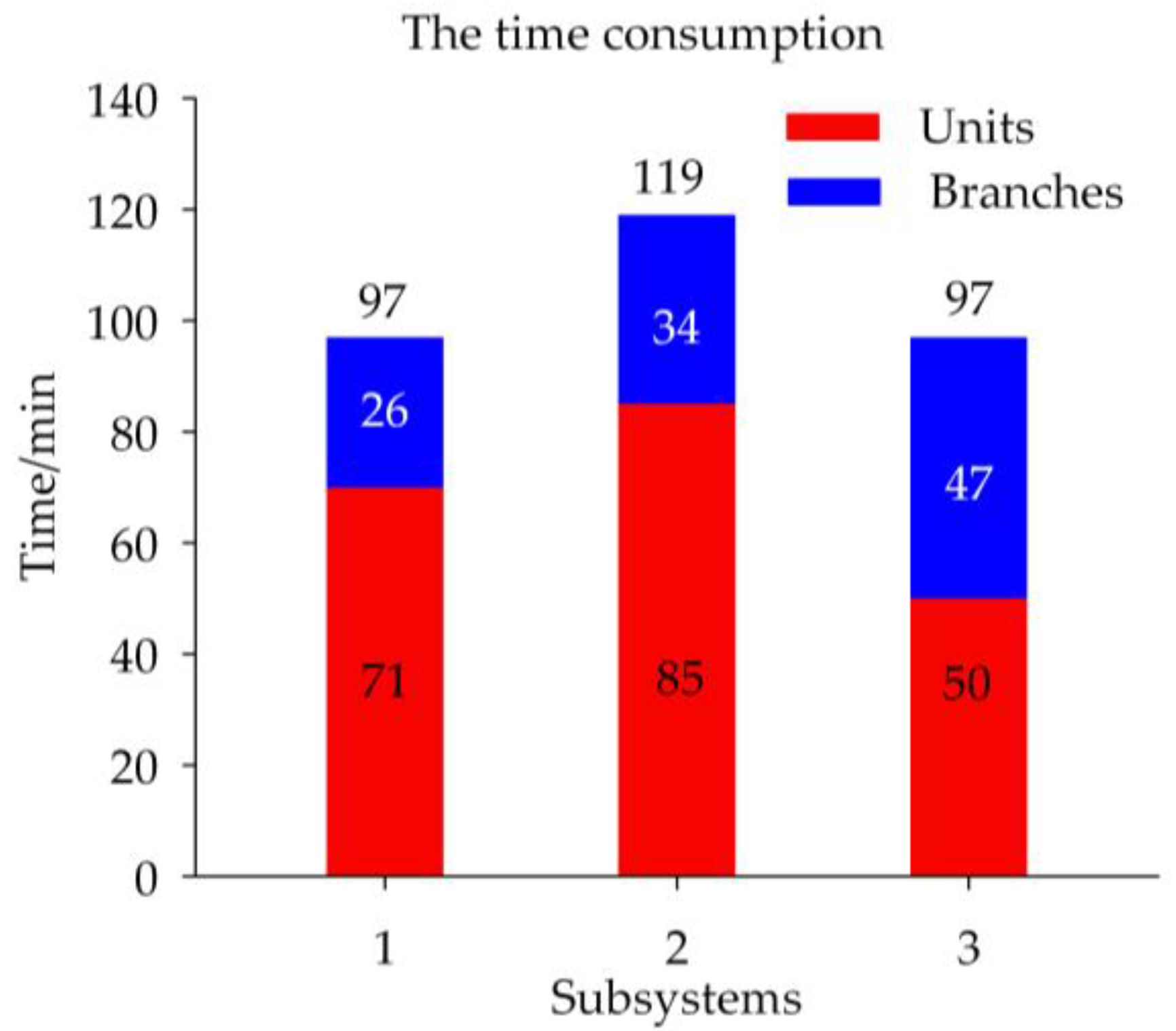
| 1 | 1901.3 | −565.8 | 97 |
| 2 | 1689.7 | −1095.2 | 119 |
| 3 | 1171.8 | −1831.9 | 97 |
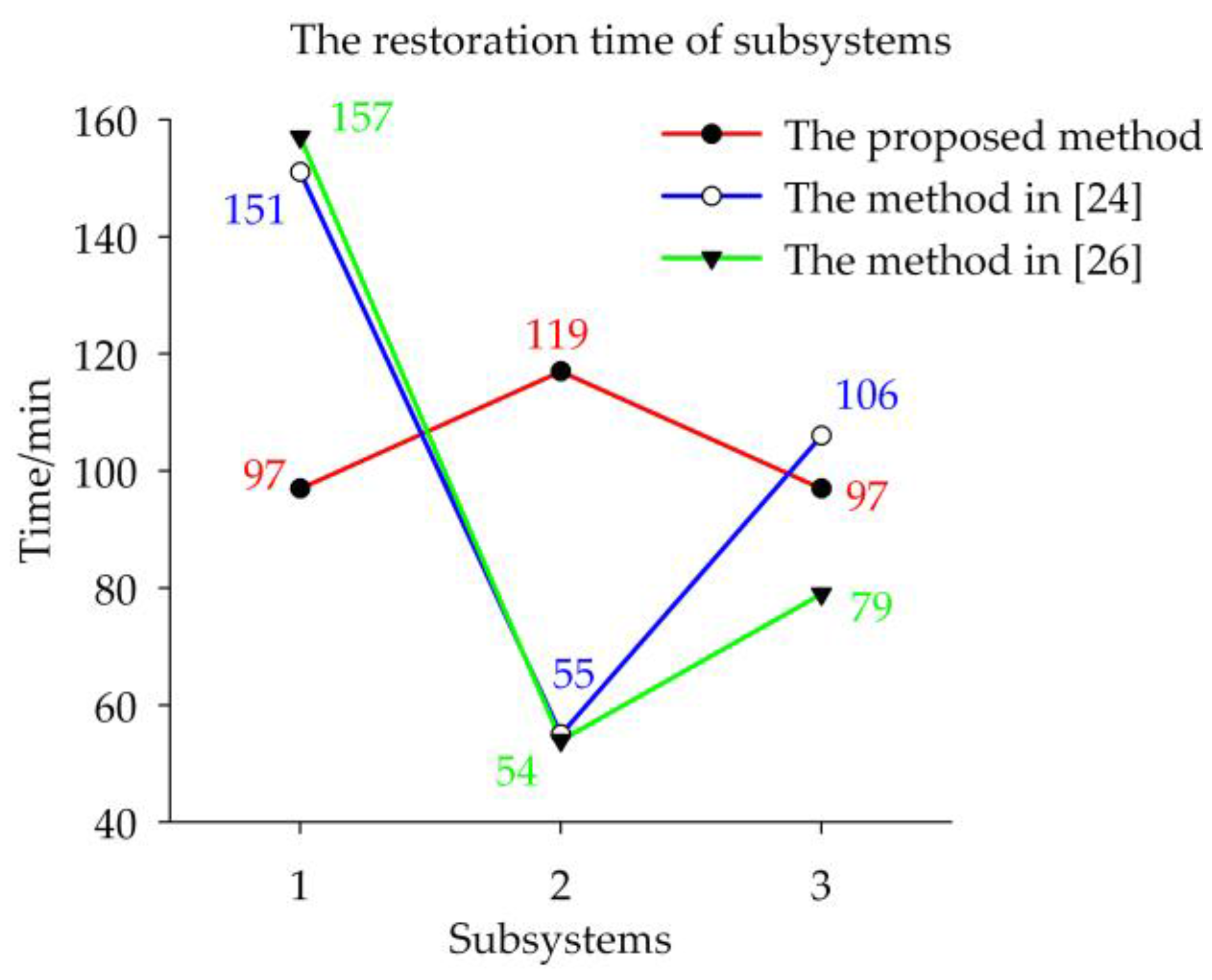
| Methods | IORL of Subsystems/MW | IMODL of Subsystems/MW | SRT of Schemes/Min | ||||
|---|---|---|---|---|---|---|---|
| Sub.1 | Sub.2 | Sub.3 | Sub.1 | Sub.2 | Sub.3 | ||
| Proposed method | 1901.3 | 1689.7 | 1171.8 | −565.8 | −1095.2 | −1831.9 | 119 |
| Method in [24] | 2671.3 | 919.7 | 1171.8 | −1880.8 | −641.2 | −970.9 | 151 |
| Method in [26] | 2513.3 | 919.7 | 1329.8 | −1661.8 | −821.2 | −1009.9 | 157 |
| Subsystems | IORL/MW | IMODL/MW | Restoration Time/Min |
|---|---|---|---|
| 1 (Black-start 31) | 2050 | −43 | 1004 |
| 2 (Black-start 54) | 1911.64 | −85.44 | 833 |
| 3 (Black-start 87) | 2009.4 | −118.4 | 717 |
| Subsystems | IORL/MW | IMODL/MW | Restoration Time/Min |
|---|---|---|---|
| 1 (Black-start 31) | 2061 | −29 | 1071 |
| 2 (Black-start 54) | 1830.6 | −58.44 | 768 |
| 3 (Black-start 87) | 2009.4 | −118.4 | 717 |
© 2017 by the authors. Licensee MDPI, Basel, Switzerland. This article is an open access article distributed under the terms and conditions of the Creative Commons Attribution (CC BY) license (http://creativecommons.org/licenses/by/4.0/).
Share and Cite
Li, C.; He, J.; Zhang, P.; Xu, Y. A Novel Sectionalizing Method for Power System Parallel Restoration Based on Minimum Spanning Tree. Energies 2017, 10, 948. https://doi.org/10.3390/en10070948
Li C, He J, Zhang P, Xu Y. A Novel Sectionalizing Method for Power System Parallel Restoration Based on Minimum Spanning Tree. Energies. 2017; 10(7):948. https://doi.org/10.3390/en10070948
Chicago/Turabian StyleLi, Changcheng, Jinghan He, Pei Zhang, and Yin Xu. 2017. "A Novel Sectionalizing Method for Power System Parallel Restoration Based on Minimum Spanning Tree" Energies 10, no. 7: 948. https://doi.org/10.3390/en10070948
APA StyleLi, C., He, J., Zhang, P., & Xu, Y. (2017). A Novel Sectionalizing Method for Power System Parallel Restoration Based on Minimum Spanning Tree. Energies, 10(7), 948. https://doi.org/10.3390/en10070948