1. Introduction
Just like the offshore wind farms, large tidal current turbines are often located in remote offshore areas where weak grids and unbalanced grid voltage conditions are a common problem [
1,
2]. Many tidal current turbines are connected in a distribution grid where asymmetrical loads, asymmetrical transformer windings or transmission impedance and transient faults (voltage dip) will be the typical sources of the problem, resulting in unbalanced operations [
3,
4]. The doubly fed induction generator (DFIG), as the most popular form of tidal current energy generation [
5], is very sensitive to unbalanced operation of a grid due to its direct coupling to the grid [
6,
7].
In recent years, lots of research efforts have been devoted to improving the performance of the steady-state and transient response of DFIG tidal turbines under symmetrical supply voltage [
8,
9,
10]. In reality, however, asymmetrical faults happen much more frequently than symmetrical faults [
11]. Furthermore, it is recognised that both transmission and distribution networks could experience voltage imbalance, which can also occur in a weak power grid even during normal operations [
12,
13,
14,
15]. A weak power grid is one where changes in real and reactive power flowing into or out of the network will cause significant changes in the voltage on the network, which is also referred to as having a low short-circuit level or a low fault level [
16,
17]. Networks in offshore areas are generally weaker than in mainland or industrial areas. If this is not taken into account by DFIG control systems, the tidal current turbines might have to be disconnected from the network under unbalanced voltage conditions due to the excessive stator current imbalances, and power and torque oscillations [
18,
19].
In order to tackle the problems, recent studies have focused on the impact that the unbalanced voltage has on DFIG turbines [
20,
21]. All of them show that even a slight imbalance could have a clear influence on rotor losses and torque pulsations [
3,
22]. The effects of voltage imbalance on power converters, due to the ripples in the output currents and the DC-link voltage, are also taken into account and a series of strategies have been proposed to minimize these effects [
23,
24].
Nevertheless, the detailed effects of DFIG on stability of a distribution grid under different load factors of the tidal current turbine plant and unbalanced grid voltage conditions are still not fully known [
25,
26,
27]. In this paper, we study the effect of addition of DFIG tidal current turbines on the performance of a distribution grid system during abnormal operating conditions. An equivalent electrical grid and its mathematical model under unbalanced network conditions are described in
Section 2 and
Section 3, respectively. In
Section 4, the effect of DFIG tidal current turbines on stability of the distribution grid system due to factors such as the power rating, the connection distance and the grid voltage dip is discussed. Finally, conclusions arising from this research are summarized in
Section 5.
2. A Distribution Grid
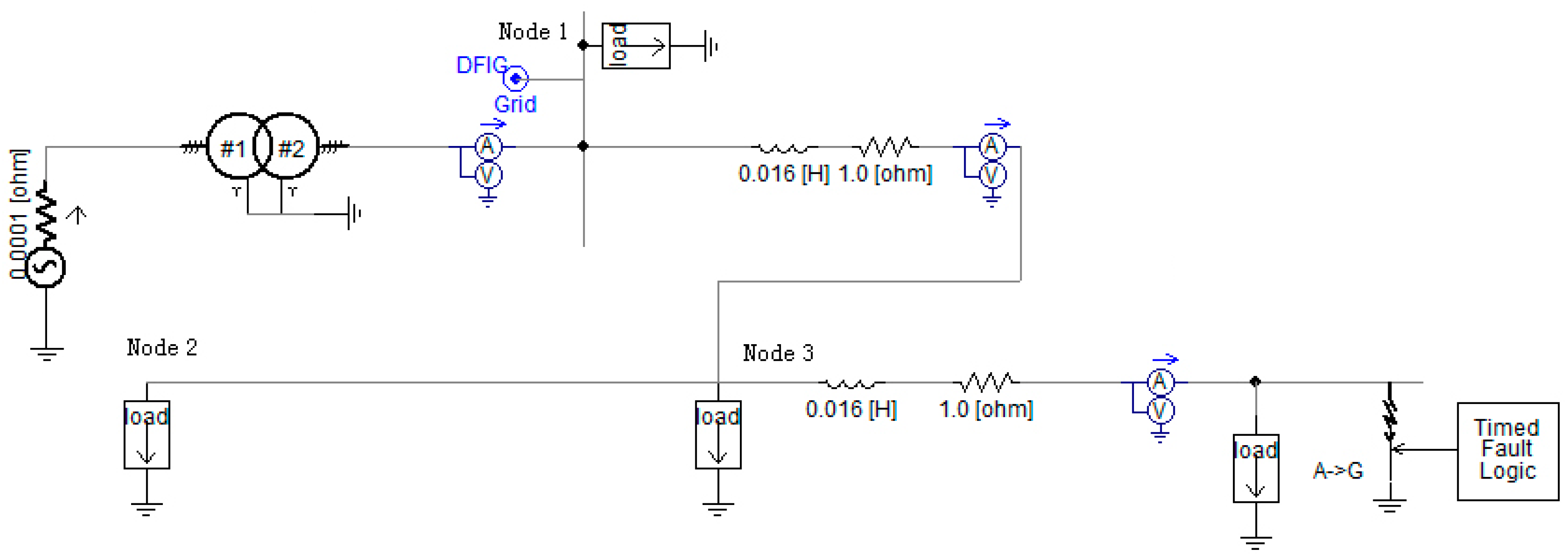
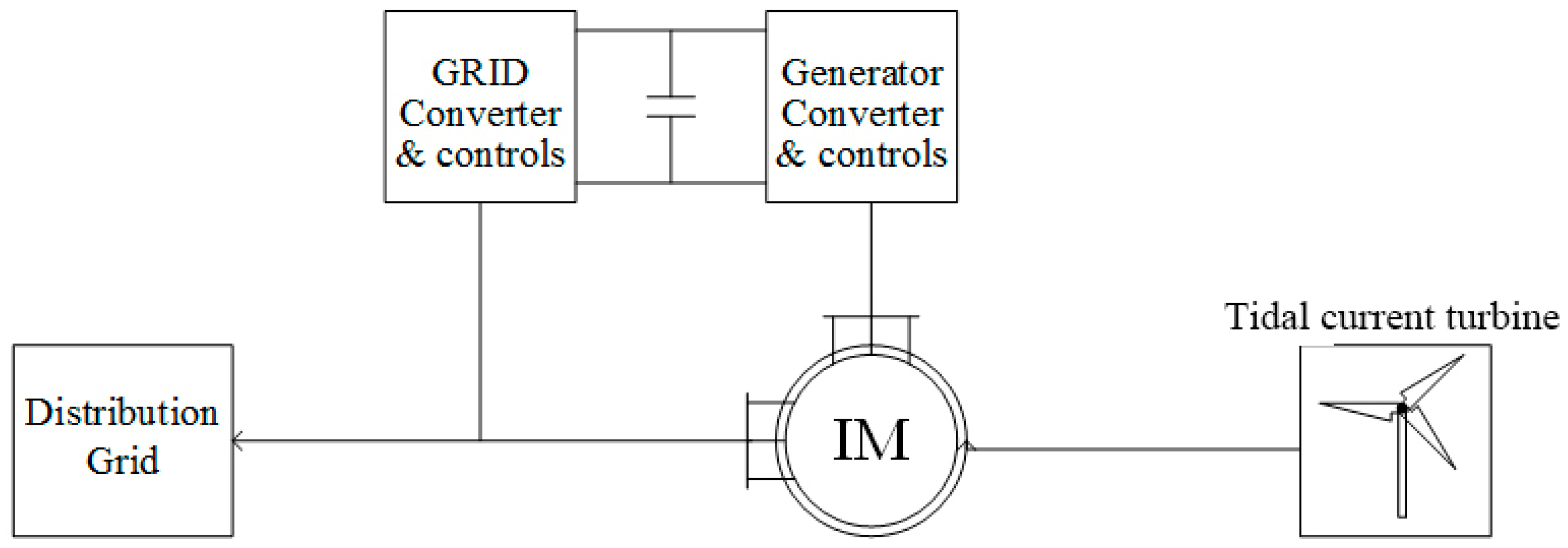
Distribution grid test feeders with a 2 MW, 1 kV DFIG tidal current turbine added is shown in
Figure 1. The grid system is modelled by a three-phase voltage source of 300 MVA and a three-phase transformer (the voltage level of primary and secondary windings is 34.5 kV and 12.47 kV, respectively). In this study, fixed load characteristics are considered, which are represented by rated real (
P) and reactive (
Q) powers. The load at node 1 is set to 2.133 MW and 1.6 MVAR while the loads at node 2 and node 3 are both set to 0.266 MW and 0.2 MVAR
The connection of a distributed generation (DG) unit to a radial distribution system could lead to situations that are not normally supported by the network in case of faults. This model allows the connecting of DFIG tidal current turbines at one node whilst applying a fault component at another node in the system. Then, the power flows of the loads and of the grid system are monitored using a combination of current (A) and voltage (V) meters in order to determine the necessary protection level and to compare the system performance, of which DFIG tidal current turbines are not connected.
Figure 1 also shows the location of the DFIG turbine to be added and the timed fault logic within the grid system. In order to evaluate system stability performance, we simulated a single phase fault on the three-phase line, where phase A is set to a phase-grounded fault while phases B and C are in the normal conditions. Various scenarios with regards to load factors were tested and the responses at three nodes in the system were examined.
Figure 2 shows the complete model of a DFIG tidal current turbine added to the distribution grid [
7]. The DFIG uses two pulse width modulation (PWM) voltage fed current regulated inverters that are back-to-back connected in the rotor circuit. The DFIG turbine is controlled by a tidal current governor with an initial pitch angle, an aerodynamic power coefficient
Cp of 0.38 and a power demand being predefined. The fluid is considered as sea flow and the density is about 1.025 × 10³ kg/m
3. The parameter of DFIG is shown in
Table 1. The induction machine is started initially in speed control mode during the initial transients and then switched over to torque control after reaching steady-state. Pitch control is not included in the simulation since it would not be activated until a few seconds after the fault and therefore does not affect the behaviour of the system during the fault.
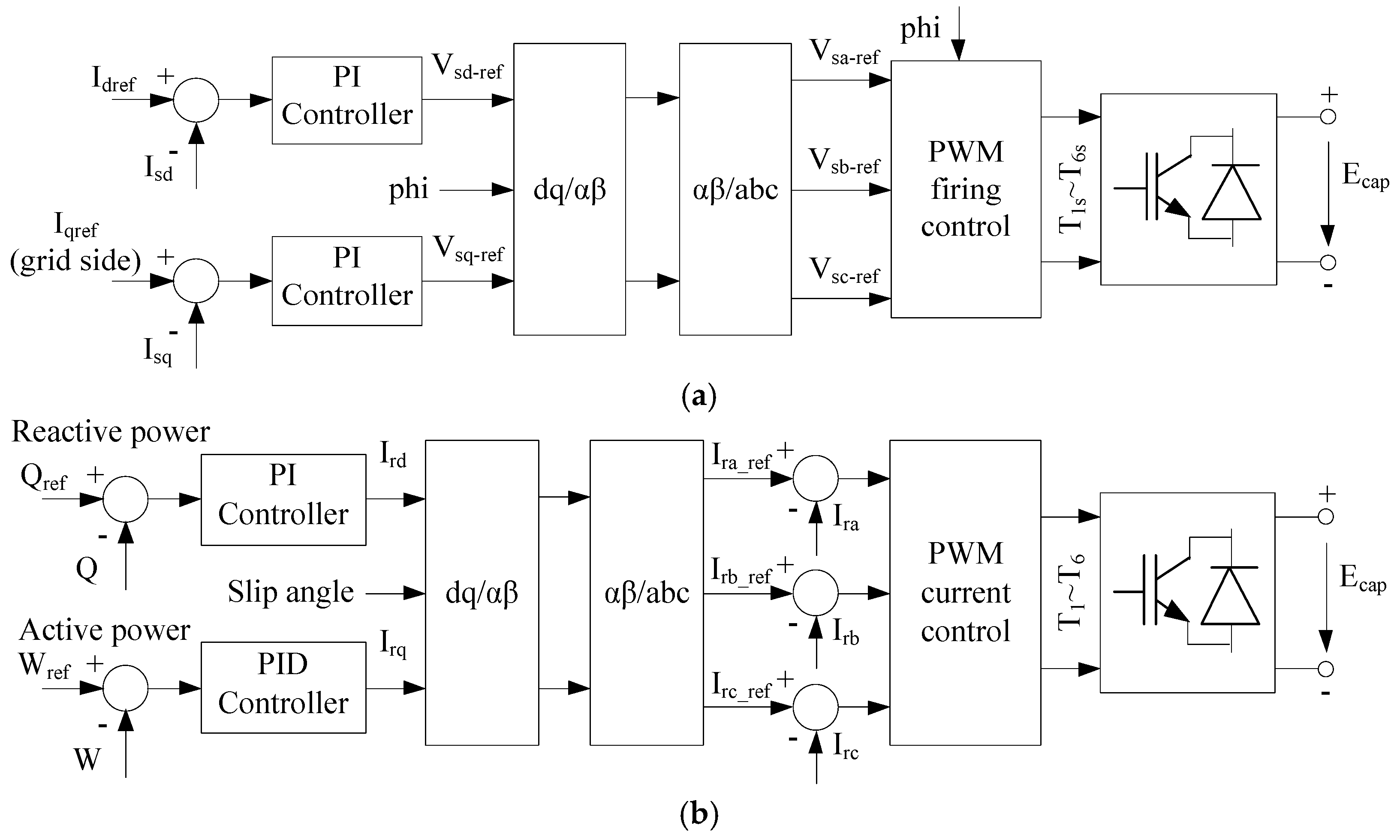
The block diagrams of induction machine control for the DFIG tidal current turbine is shown in
Figure 3. In the rotor side converter (RSC), as shown in
Figure 3a, the active power is generated with regards to tidal current speed and tidal current turbine characteristics while the reactive power reference is set on the base of the utility demand. The control scheme in the RSC converter is to ensure the rotor reference currents
Ira_ref,
Irb_ref and
Irc_ref are generated by obtaining the correct values of the direct and quadrature currents
Ird and
Irq in a synchronous rotating
dq axis frame through the use of PI error compensators, and then force the active and reactive powers follow the reference signals. By comparing the rotor reference currents and the measured instantaneous values
Ira,
Irb and
Irc of the rotor currents, the PWM circuit generates the switching signals
T1–
T6 to the converter devices. The desired rotor reference currents
Ira_ref,
Irb_ref and
Irc_ref can be readily calculated using the inverse
dq transformation (a
dq/αβ transformation followed by a αβ/
abc transformation in the diagram) with regards to the slip angle. The slip angle represents a relative difference between stator flux and rotor position.
In the grid side converter (GSC), as shown in
Figure 3b, the selection of
Idref is for keeping the capacitor voltage
Ecap at its rated value by adjusting the active power. The direct and quadrature currents
Isd and
Isq are calculated from the measured instantaneous values of the stator side currents using the
dq transformation. The reference voltage
Vsd_ref is controlled by the capacitor voltage error while
Vsq_ref is controlled by the error between the setting and actual value of the stator side reactive power. The reference voltages
Vsa_ref,
Vsb_ref and
Vsc_ref of the three phase voltages can then be generated using an inverse
dq transformation with regards to the AC grid voltage reference angle
phi. In the PWM circuit, each of the phase reference voltages is compared with a high-frequency triangle waveform to generate the firing pulses signals
T1s–
T6s to the GSC devices.
With the above control schemes, the active and reactive powers of the DFIG tidal current turbine can be controlled independently. The DFIG is also capable of simultaneous capturing maximum power of tidal current energy under the fluctuating tidal current speed and improving power quality.
3. Network Modelling
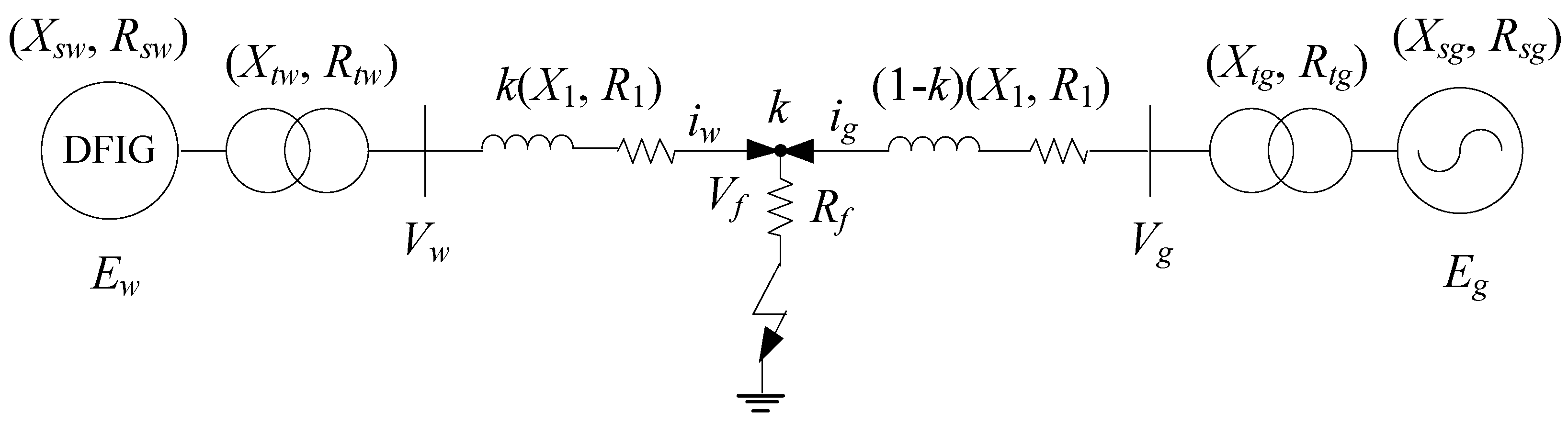
The study considers a power system that is connected with DFIG tidal current turbines with a transmission system for tidal current power delivery. A simplified model in the form of lumped parameters is shown in
Figure 4 [
28], where only one phase is drawn. The power sources at the DFIG side and the grid side are connected via transformers and a transmission line with local loads to carry power from DG units to the electrical grid. For the tidal current turbines, one of the issues relates to the transmission system linking between the offshore tidal current farm and the on-land electrical grid. For small-scale tidal current turbines, a short distance high voltage alternating current (HVAC) system is normally preferred due to its advantage of low cost, which is the focus of our studies in this paper. These lines can also represent a certain connection distance between the tidal current farm and the electrical grid system. It is worth noting that loads shown in
Figure 1 can be equivalently considered as load conditions when configuring the simplified electrical power system.
The tidal current turbine and power source of the grid system are assumed as ideal three-phase sources and the transformers have an ideal turn ratio with only leakage impedance being considered. The transmission line is represented by its lumped impedance by neglecting the capacity of phase-to-phase and the capacity of phase-to-ground. Nevertheless, the simplified model can still adequately represent the right AC components and asymmetric DC components of voltages and currents under the system’s unbalanced fault conditions.
Take phase A as an example. Under normal conditions without any faults, the differential equation of phase A can be written as below, where the boundary condition
applies, and
and
are the phase A currents supplied from DFIG and grid sides of the line, respectively,
where
and
represent the phase A source voltages at both sides, respectively. The parameter
f is the power line frequency of the electric power grid. The parameters
and
denote the impedance of the AC source representing the DFIG, while
and
denote the impedance of the AC source representing the grid system. The parameters
and
are the leakage impedance of the tidal current-turbine side transformer while
and
are the leakage impedance of the grid side transformer.
and
are the positive sequence impedance of the line.
When a phase-A grounded (AG) fault occurs at location
k, as shown in
Figure 4, then
, the zero sequence current of DFIG side of the line
, and the zero sequence current of grid side of the line
, where
and
are three-phase currents supplied from both ends. Hence, the electrical topology of the system will change accordingly. The differential equations of phase A can now be described by Equations (2)–(6), where
is the voltage at the fault location and
represents ground transient resistance;
and
are the zero sequence voltage at the neutral connector of the transformers of both sides, respectively;
and
are the zero sequence impedance of the line, and fault location k is represented by its percentage (0–1) of the line:
The currents of the faulty phase will be greater than the rated current of the system, which can be rearranged as below:
The differential equations related to phases B and C can be obtained similarly; therefore, the unknown phase currents of both sides can be resolved. Having obtained the phase currents, bus voltages at both sides can be computed based on the Equations (9) and (10) by taking phase A as the example. By arbitrarily setting the initial load condition and fault situation, the system under normal and unbalanced fault conditions can be examined:
The above differential and algebraic equations can be solved using a suitable iterative numerical algorithm such as a higher order Runge–Kutta or trapezoidal integration method to minimize the round-off errors in calculation. Although the DG system model shown in
Figure 4 is a simplified one and the Equations (2)–(6) only consider the positive sequence components, undoubtedly, the model and solutions still can provide insight into the dynamics of the system behaviour under fault conditions in a very straightforward way [
29]. It is worth noting that typical distribution network configurations and models are much more complex compared to the one shown in
Figure 4. For the unsymmetrical fault conditions, a negative sequence network that omits all positive-sequence generators needs to be considered under such conditions. For example, for a single-phase-to-ground fault, the negative sequence network is connected in series with the positive sequence network while, for a phase-to-phase fault or a phase-to-phase-ground fault, the negative sequence network is connected in parallel with the positive sequence network. Additionally, the lines have been modelled as lumped longitudinal impedances whilst, in reality, unbalanced impedances that also consider transverse parameters need to be taken into account. Equations (2)–(6) also neglect the mutual coupling between the phases and the presence of transverse parameters. Therefore, simulation tools such as EMTP, PSS/E and PSCAD/EMTDC can be used for the dynamics analysis of the power system [
30,
31]. In our study, we use the power system commercial software platform PSCAD/EMTDC because it is capable of modelling the dynamics of a complex electrical system in details under normal and fault conditions.
4. Investigation of Effects of Doubly Fed Induction Generator (DFIG) Tidal Current Turbines
4.1. Addition of a DFIG Tidal Current Turbine
Simulations of the original network without DFIG tidal current turbines connected are firstly performed in order to establish a baseline system performance. The simulations are then turned into connecting the DFIG at one node and applying a fault component at another node in the system. The currents and voltages are monitored in order to determine the necessary protection level, and the power flows in terms of both active and reactive powers are also monitored to compare the system performance with and without DFIG connected. In the simulations, the system is allowed to reach a steady state after initial start-up, and a single phase-grounded fault is applied to phase A at 15 s with fault duration of 0.5 s. Simulation time was set to 20 s, which is sufficient for each case to re-reach steady state.
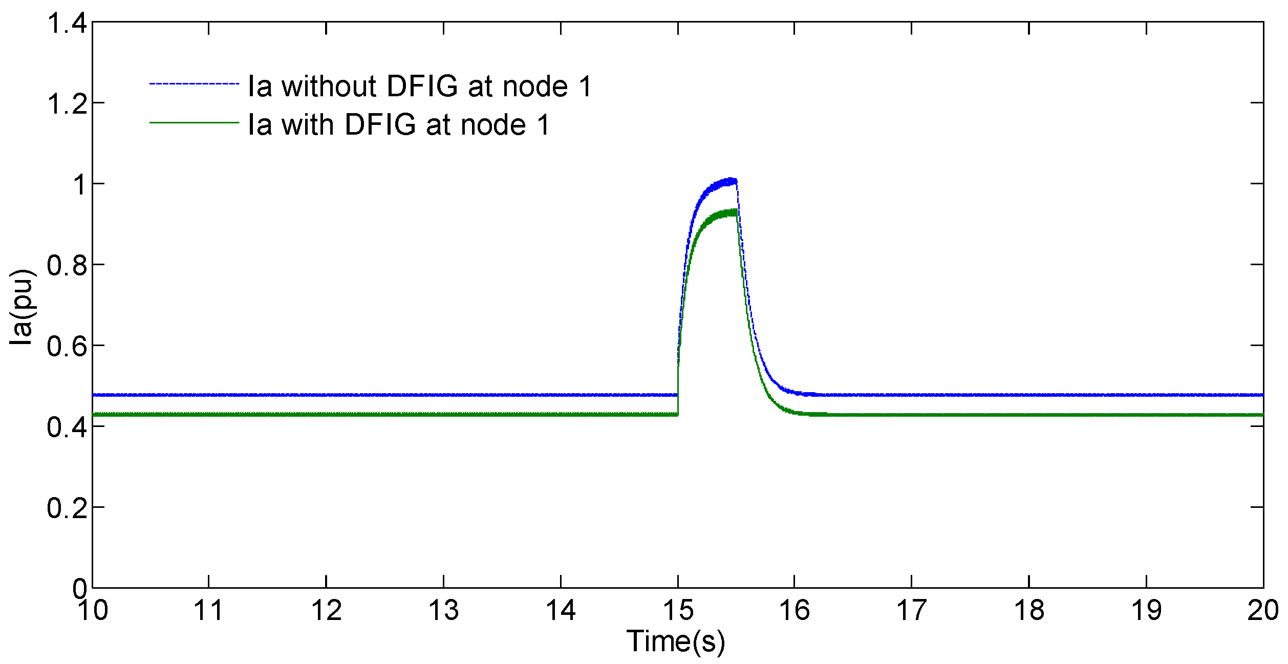
Figure 5 shows a simulation with the grid system alone, followed by the addition of a DFIG tidal current turbine to node 1 and application of an AG fault at node 3 in the system. As can be seen from the results, the peak value of phase-A current during the fault at node 1 is lower with DFIG than without DFIG. Thus, the overall fault detection level of the system must be set to below the smaller value but above the normal operational magnitude of the power system when operating alone, or the grid engineer must know when the DFIG is in on-line or off-line operation so that the protection level is modified accordingly [
32].
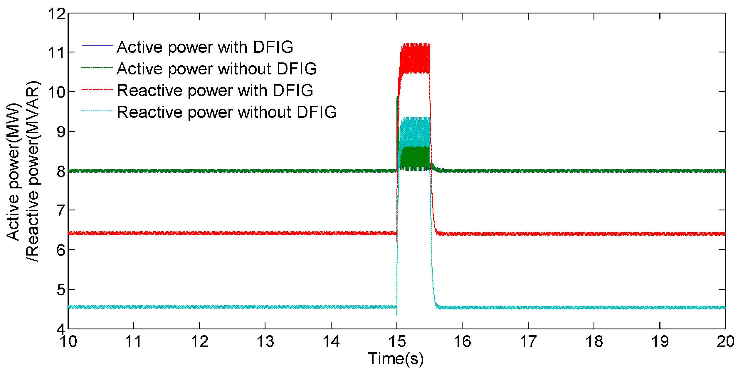
There is no instability problem for active and reactive powers during the observation period, as shown in
Figure 6. Therefore, when connected to node 1, the DFIG tidal current turbine will supply more active power, thus increasing the power output level of the system. The active power also has less power fluctuations during the fault.
Figure 6 also shows that the reactive power is relatively lower in a steady state; however, there are significantly increased oscillations in reactive power during the fault in the case when the DFIG is connected. This is because the DFIG tidal current turbine added in the system can greatly improve the low voltage ride through (LVRT) capacity by providing less active power fluctuations and good reactive power compensation during the grid fault period.
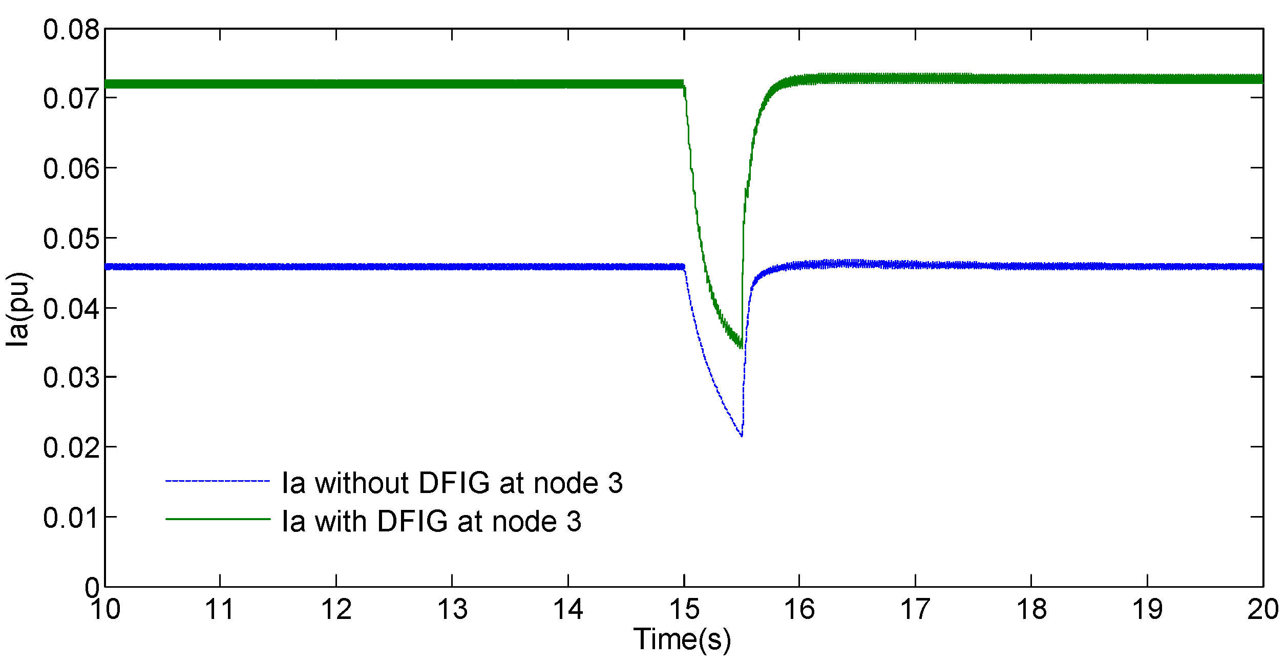
Next, we apply the AG fault at node 3 and then perform the same simulations with and without the DFIG connected to node 3 as we previously did at node 1.
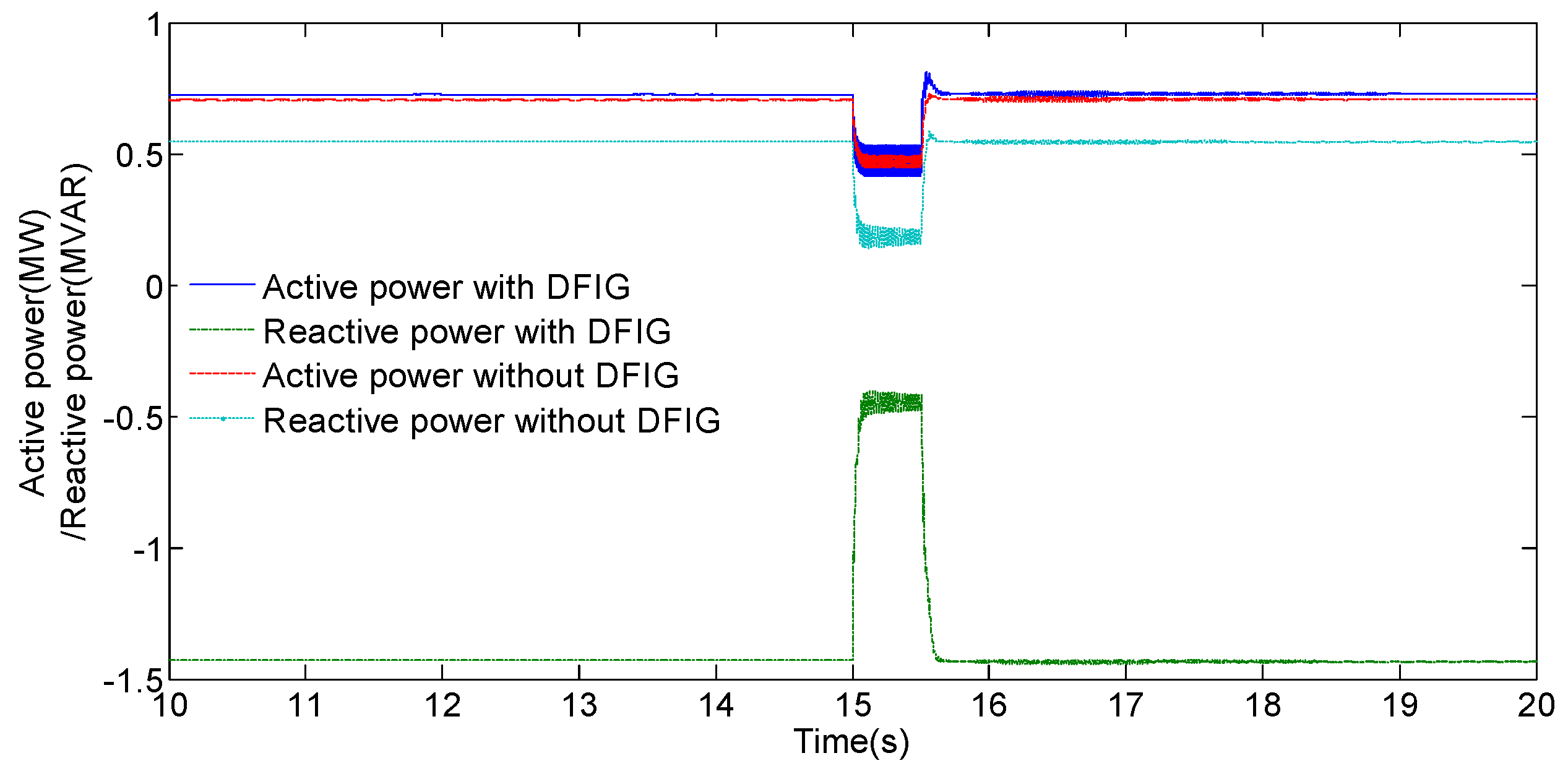
Figure 7 and
Figure 8 show that, with the DFIG connected to node 3, the phase-A current and the active power are larger in steady state and the phase current also has a larger current drop during the fault. This may result in a serious problem if the larger current or active power at node 3, due to the addition of DFIG, exceeds the maximum interrupting rating of the circuit breaker. Therefore, the circuit breaker must be changed to meet the requirements. It can also be seen from
Figure 8 that, during the fault, the reactive power with DFIG connected is increasing, which would be helpful for the recovery of the system during the fault.
Therefore, the addition of a DFIG tidal current turbine to the distribution grid system cannot be done directly and simply. As we know that the distribution system is normally a radial system, the different location at which a DG unit like DFIG turbine is connected and where a fault is applied can lead to totally different results. Consequentially, the protection settings and circuit breakers of the system may need to vary to accommodate the system configuration requirements.
4.2. Effect of the Rated Power
In this subsection, we discuss the system stability of the grid system under unbalanced voltage conditions when a tidal current power plant operating at a different level of the rated power is attached. The tidal current power plant is added to node 1, while the fault is applied at node 3. In this study, the DFIG is started in speed control mode with the rotational speed of the generator being set to the rated speed up to 1.1 per unit (pu) speed and is then switched over to torque control after 0.5 s of the initial transients of the machine, eventually reaching steady-state.
For this simulation, the tidal current power plant is set to generate 3.5 MW and controls its own terminal voltage. Several levels of power generation have been investigated in order to determine how low the power can be set to whilst still maintaining the system stability in the operation under different unbalanced voltage conditions. Normal operation starts from t = 0 s to t = 12 s. Then, an unbalanced grid fault (AG fault) with a duration of 500 ms is applied. Tidal current speed is assumed to be constant during the simulation. Initially, the tidal current power plant is assumed to operate at 1 MW or 30% of its rated output power.
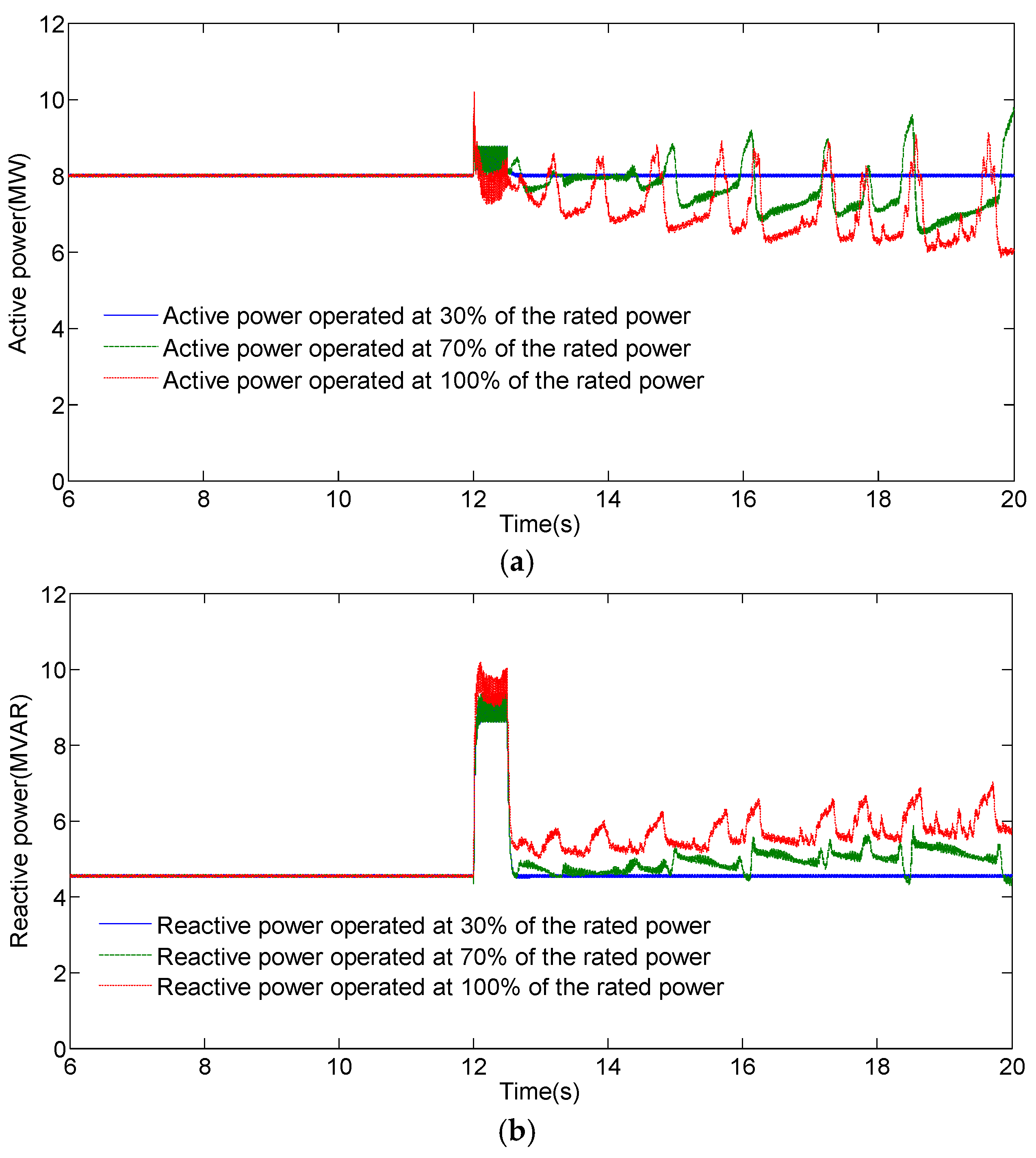
As shown in
Figure 9, when the turbine is operating at 30% of its rated output power, the active and reactive powers of the system return back to the pre-fault conditions after the fault ends. It can be seen that there is no instability problem during the observation period. Hence, the power system is stabilized when a 3.5 MW DFIG tidal current farm is connected at node 1 and operates at 1 MW output or 30% of its rated output power.
Let us consider what happens if we increase the output power to 2.45 MW or 70% of its rated output power. As shown in
Figure 9, both the active and reactive powers at post-fault condition settles at a different value from the pre-fault value because of the higher system impedance when a single phase fault happens. Oscillations in the curves after the clearance of the fault are clearly evident compared to the pre-fault data. This implies that the system begins to lose its stability after the fault ends when the output power of DFIG is increased to 2.45 MW or 70% of its rated output power. Consequentially, 70% rated output power can be considered as a critical point of the system being studied in this paper. Once the rated power was set to higher than this critical point, the grid system will lose its stability.
Figure 9 also shows the case when the tidal current farm is operated at 100% rated power of 3.5 MW. The tidal current speed is set to 3.5 m/s, which is higher than the rated tidal current speed, in order to keep the DFIG on a full rated output power. The value of active power within a pre-fault period is larger than that during the post-fault period, while the value of reactive power has the opposite situation. Compared to the 70% case, it can be found that the active power operating at 100% rated power exhibits oscillations with a higher frequency. On the other hand, reactive power is very responsive, implying that more reactive power comes from the full rated power than from the 70% rated power of the tidal current plant.
With more and more DFIG tidal current turbine generators being integrated into the power system, the potential occurrence of the oscillatory phenomenon due to the induction generator effect and torsional interactions is well known as the subsynchronous-resonance (SSR) issues. The SSR problems can be mitigated with sophisticated controller techniques such as a flexible AC transmission system (FACTS) device and a thyristor-controlled series capacitor (TCSC) [
33,
34]. The detailed descriptions of these techniques are beyond the scope of this paper.
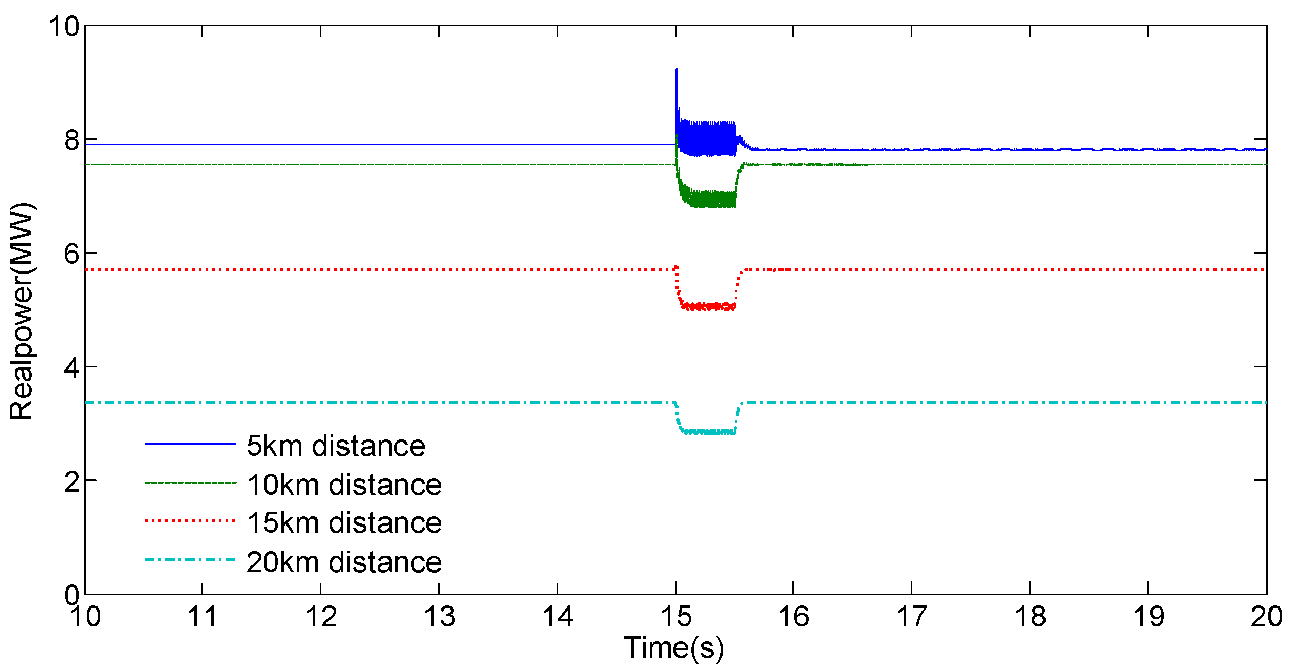
4.3. Effect of the Connection Distance
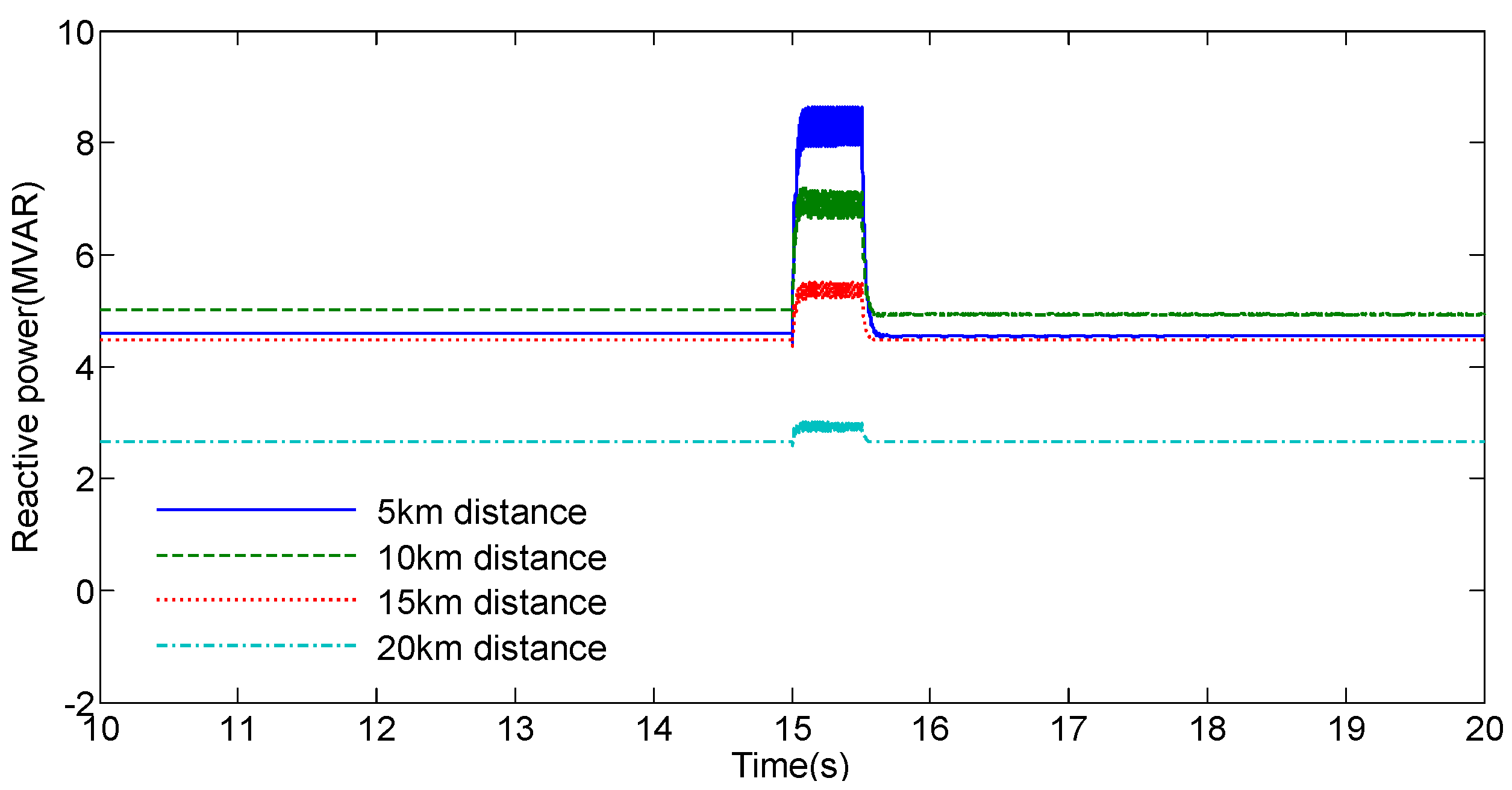
In this subsection, we perform simulations of the network with a certain connection distance between the grid source and the DFIG tidal current turbine. Take wind farms, for example, particularly small-scale ones. The HVAC system is normally preferred for short distance power delivery (less than 50 km) [
35]. Therefore, four short distances of 5 km, 10 km, 15 km and 20 km are considered for the tidal current turbine with rated power of 3.5 MW being analysed in the paper. From the simulation results, as shown in
Figure 10 and
Figure 11, we can conclude that when the tidal current turbines are added in the distribution grid, the closer to the grid source, the larger the active power of the system at node 1 would be. The same result applies to the reactive power. Additionally, the closer to the grid source, the less the oscillations of both active and reactive powers are evident during the grid fault. Furthermore, the change of active power with the connection distance seems not apparent during the fault; however, the shorter the connection distance, the larger the increase in reactive power during the fault.
4.4. Effect of the Grid Voltage Dip
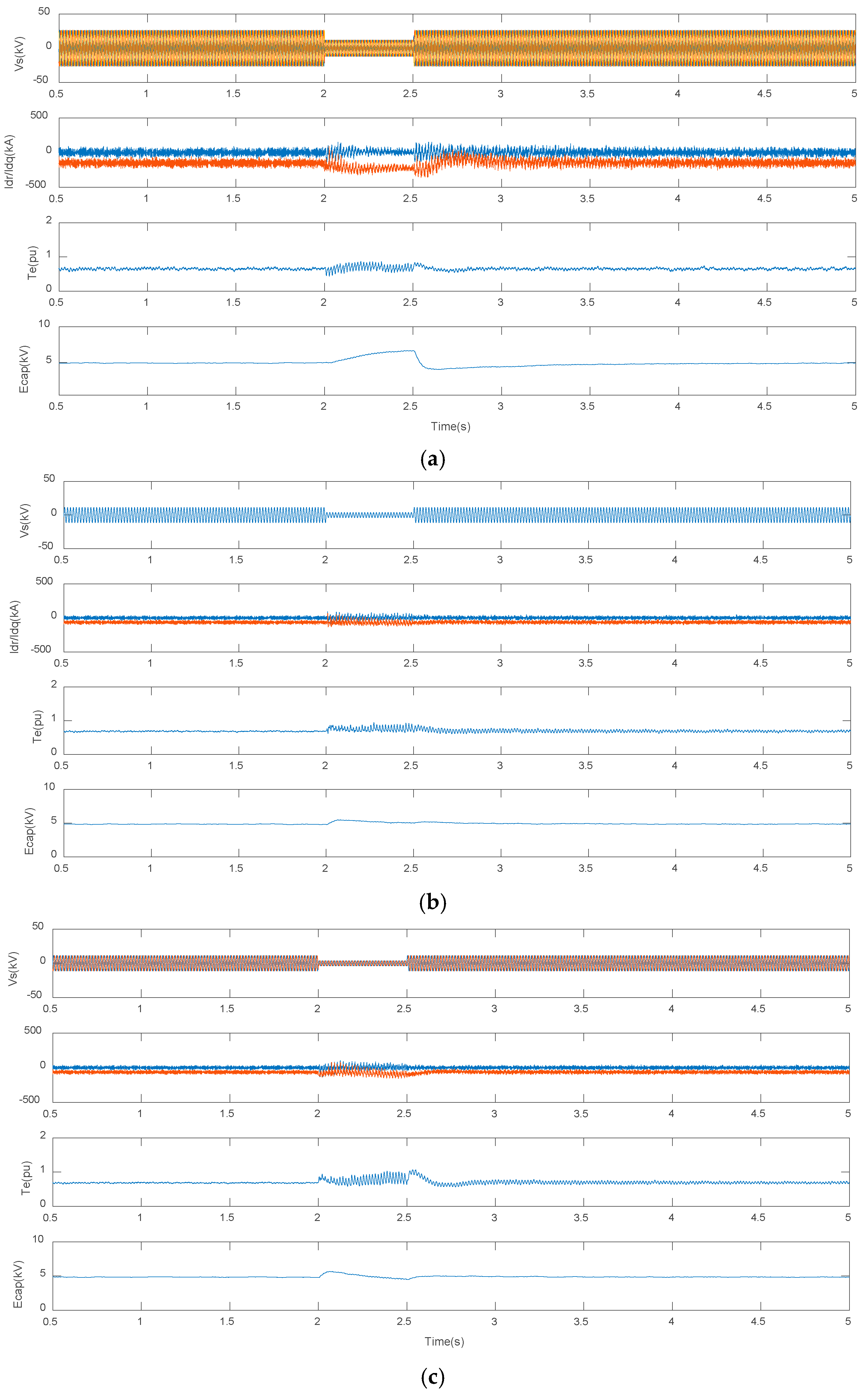
Simulation results of the DFIG tidal current turbine under symmetrical and different unsymmetrical voltage dip conditions are shown in
Figure 12.
Figure 12a shows that, under a symmetrical voltage dip situation, the severest problem is the transient overcurrent of
Id and
Iq, the two orthogonal components of the rotor current, followed by a large electromagnetic torque
Te. In the tidal current turbine control systems, the
Id component is used to regulate power factor or terminal voltage while the
Iq component is used to regulate the torque. This overcurrent problem can be generally protected by a so-called crowbar protection, which can be activated to short circuit the rotor windings during the fault and will be kept off until the stator voltage is recovered [
36,
37].
Figure 12b shows that, when an unsymmetrical voltage dip of 70% rated value occurs, the maximum rotor currents become smaller. Compared to
Figure 12b,c with two-phase unsymmetrical voltage dips of 70% rated value, it can be seen that the case with a two-phase unsymmetrical voltage dip has larger oscillations in rotor currents. Just like the situation of symmetrical voltage dip, a larger voltage dip also causes larger ripples in electromagnetic torque
Te and dc voltage
Ecap during the voltage sag period, no matter it is a single phase or two-phase unbalanced voltage conditions. It is worth noting that the amplitude of rotor current oscillations depends on the time instant at which the voltage dip applies. A new coordinated control strategy has been proposed to improve the oscillatory responses, where the RSC is controlled to eliminate the torque oscillations while the GSC is designed to obtain constant active power output and to minimize the oscillations in the DC link voltage [
38].
5. Conclusions
In this paper, we have attempted to examine the performance of a distribution grid in terms of transient stability under different unbalanced grid voltage conditions when DFIG tidal current turbines are or are not attached. A distribution grid model under the unbalanced voltage conditions has been built. The effect of the location, the rated power, the connection distance of the DFIG added in the distribution grid system and the effect of different grid voltage dip conditions on the system performance have been investigated through the extensive simulations performed by PSCAD/EMTDC. The results have demonstrated that tidal current turbines added in the distribution grid system would provide good reactive power compensation under these conditions, which can greatly improve the LVRT capacity of the system. The results has also supported the conclusion that modern DFIG tidal current power plants, equipped with power electronics and LVRT capacity, can be interconnected to the distribution grids even under unbalanced grid voltage situations without reducing stability. In this paper, the network loads are represented as fixed-power elements whilst, during fault transients, their dynamic behaviour might play a fundamental role. Future work includes the use of dynamic load models to understand the entire system dynamics during the faults. A more complex distribution network will also be examined, where unbalanced impedances that consider transverse parameters need to be taken into account.


