1. Introduction
Electric braking systems are a new type of braking system widely and continually researched in the aviation field. It makes use of electro-mechanical actuators (EMAs) instead of classical hydraulic actuators, thus getting rid of the dependence on the main hydraulic system, significantly reducing the weight and volume of the braking system, in order to improving the safety of the system, which is the development direction of braking systems in the future. Braking systems of all-electric aircraft require EMAs driven by motors to output brake pressure accurately and rapidly, and have a good tracking of the reference pressure signal.
Brushless direct current motors (BLDCMs) have been widely used with the rapid development of permanent magnet material technology, power electronics technology and other supporting technologies, as well as the continuous improvement of micro-motor manufacturing processes. BLDCMs have advantages like compact structures, higher torque inertia ratio and larger power density, which are suitable for the driving part of EMAs. Driven by BLCDMs, the electric braking system is essentially a high performance servo system, and the special application situation of aircraft puts strict demands on the control strategy of the BLDCM servo system.
It should be noted that, although modeling seeks to be exhaustive, it is not accurate enough to describe the dynamic characteristics of EMAs. The main reason is that the EMA is a complex mechatronic system, which contains backlash, friction and other nonlinear characteristics. For that reason, it is very difficult to obtain a mathematical model which can be applied to describe the dynamic behavior of an EMA accurately. EMAs work in harsh environments, where large fluctuations in temperature cause significant changes in motor parameters. The above reasons also led to the difficulty to achieve fast response and high precision of the pressure tracking effect with linear controllers. Based on the essential characteristics of the brake pressure servo, the nonlinear block diagram model is simplified. The compound disturbance is a combination of the time-varying parameter, unmodeled dynamics and external disturbance, and sliding mode control is applied to the state space model of the brake system, so as to design the control law.
Mercorelli et al. proposed two different electromagnetic motors controlled using a sliding mode approach [
1]. Su et al. addressed the problem of global finite-time stabilization of planar linear systems subject to actuator saturation [
2]. A simple saturated proportional-derivative controller was proposed. Morshed et al. designed a fuzzy second order integral terminal sliding mode controllerin [
3], which places the system on a sliding surface in the initial state based on [
4]. Wu et al. designed a nonlinear dynamic sliding mode surface with terminal characteristics in [
5], but the disadvantage is that if the control parameters are chosen improperly, singular problems may arise. Yu et al. extended the terminal sliding mode (TSM) design to multi-input uncertain systems [
6]. Feng et al. subsequently improved the sliding surface, and came up with the non-singular terminal sliding mode [
7]. Yu et al. [
8] proposed a fast terminal sliding mode (FTSM) design method based on [
7]. Compared with TSM the algorithm has advantages in the convergence rate. In fact, FTSM is also considered as a combination of exponential reaching law and power reaching law, which makes the convergence speed of the system become faster when the system state is far away from or near the sliding surface. In recent years, in addition to the second order TSM methods, for example the Super-Twisting algorithm, some new TSM structures have been proposed, such as a full order sliding mode surface with terminal characteristic proposed by Feng et al. [
9], and an essential NFTSM designed by Yang et al [
10]. Feng et al. [
11] carried out low-pass filtering on the control switching terms which provided smooth control quantities and proved that the filter has no effect on the stability of the TSM when appropriate switching terms are used. Similarly, Wang et al. designed a control switch with filter, which ensures the global stability of the system and reduces the high frequency chattering [
12]. In [
9] is worth noting that the filtering method used to design the switching control term must be combined with the stability analysis method. Furuta et al. [
13] proposed the concept of sliding sector, defining define two sliding surfaces, dividing the state space into different sectors, designing different switching control items, constructing a continuous switching controller so that the control signals are continuous. The sliding sector method greatly reduces the sliding mode chattering frequency, but its defect is that when the state trajectory is far from the equilibrium point, the saturation characteristic width is large, which lead to a poor robustness of the system. Suzuki et al. [
14] and Pan et al. [
15] studied design methods for the time invariant sector and the time variable sector, respectively. Powly et al. [
16] combined the reaching law and a sliding sector method, and designed a sliding mode controller for missile attitude control. Li et al. used a discrete-time nonlinear observer (DNLO) for estimation the state of charge (SOC) of lithium-ion batteries [
17]. The results verified that DNLO has better performance in reducing the computation cost than the extended Kalman filter (EKF) algorithm. Huangfu et al. proposed a super-twisting sliding mode algorithm to improve the system stability [
18,
19].
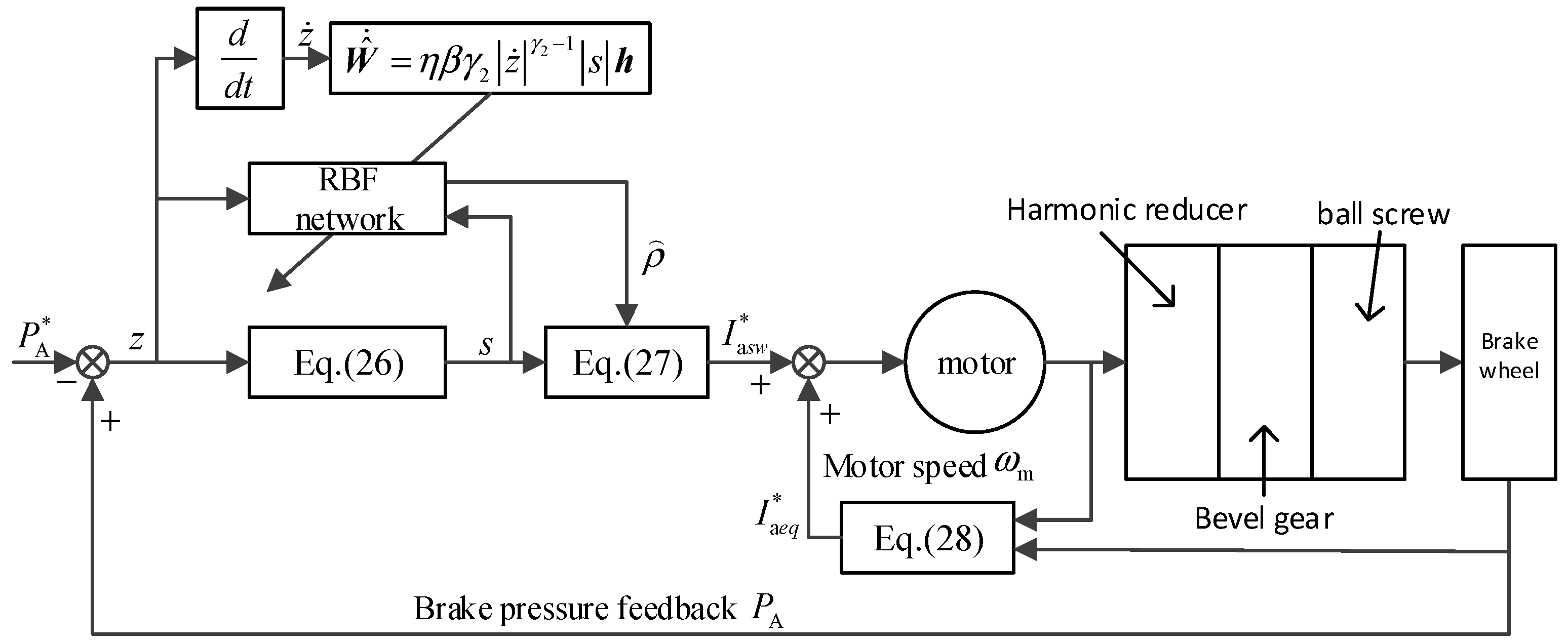
According to the characteristics of the EMA pressure servo system, this paper proposes an adaptive non-singular FTSM control scheme. On the basis of [
10], a RBF neural network is used to deal with the difficulty of estimating the upper bound of the uncertain compound disturbance in the system. There is a singular problem in the design of the traditional FTSM, and the proposed NFTSM, in essence, avoids singularity and is applicable to system which has external disturbances and parameter uncertainties. RBF has strong input and output mapping functions, and the theory proves that the RBF network is the proper choice to complete the mapping function in the feed-forward network. The switching gain of the controller is adjusted automatically by the system state information, which improves the adaptive ability of the EMA controller, reduces the conservativeness of the sliding mode control design, and effectively suppresses the chattering of the sliding mode control, while improving the performance of the pressure servo and the adaptive ability of the system.
The remainder of the paper is organized as follows:
Section 1 introduces the problem of the electric braking system and EMA system.
Section 2 presents the braking system principle and the EMA structure, and then establishes the EMA mathematical model by combining with the transmission mechanism model, to get the overall the nonlinear block diagram model of the EMA brake system.
Section 3 presents the adaptive NFTSM controller and RBF neural network design method, and the convergence property in finite time is analyzed by a Lyapunov method.
Section 4 gives some results and conclusions.
The main contributions of this paper can be summarized as follows: firstly, the paper proposes a feasible nonlinear control method for brake EMA systems and obtains a better control effect. Secondly, because of the restraint of the model uncertainty influence and external disturbances, the proposed algorithm did not change the traditional brake control structure, which improves the control accuracy and response speed. Thirdly, the new brake control system is fully validated experimentally.
2. EMA Mathematical Model for the Electric Braking System
2.1. EMA Mathematical Model
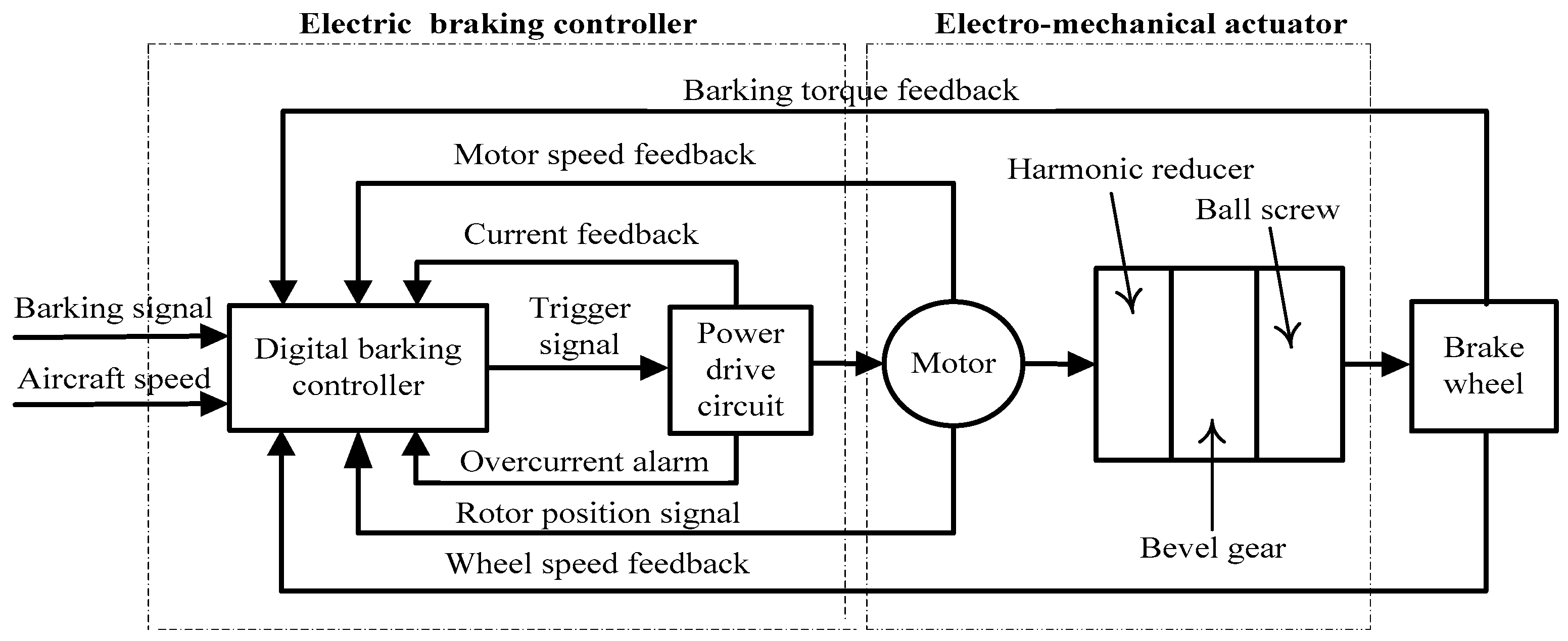
An electric braking system contains an anti-skid braking controller, braking power driver, EMA, brake wheel and related sensors. The basic system structure is shown in
Figure 1. The braking principle of the electric braking system is not substantially different from that of a hydraulic braking system. The anti-skid braking controller serves as the control unit of the braking system, receiving the braking command signals, the aircraft speed signals and the wheel speed signals. The anti-skid controller generates the corresponding pressure control signal input to the drive circuit to driving the motor, and then drives the output pressure of the ball screw to the disc, generating the corresponding torque, and making the actual pressure follow the desired pressure signal through the pressure feedback loop. The tracking of a given slip ratio is eventually realized, at the same time, this prevents the locking of the wheels when braking with great urgency. According to the whole structure, the whole electric braking system is a double closed-loop control system, which is composed of the slip ratio and the pressure feedback.
As the internal dynamic characteristics of BLDCM are not the main focus of this paper, the DC motor mathematical model used in the EMA is suitably simplified. Once the simulation model is established, in the EMA, the DC motor is controlled with a variable armature voltage, thus we can simplify the brushless DC motor as follows:
where
Uc is armature voltage (V),
Rm is armature resistance (Ω),
Ia is armature current (A),
L is armature inductance (H),
Ea is induced electromotive force (N),
Ke is back electromotive force constant,
KT is torque constant.
It can be seen from Equations (1)–(3) that the expression of electromagnetic torque of the BLDCM is the same as that of an ordinary DC motor. The electromagnetic torque of the BLDCM is proportional to the magnetic flux and current amplitude, so the torque of the motor can be controlled by the amplitude of the output square wave current of the inverter.
By taking into account the requirements of the mechanism transmission ratio, nominal diameter d0 and ball screw lead L0, the rated dynamic load is usually determined by the maximum axial thrust of the brake disc driven by the ball screw. The inertia torque of the ball screw rod and the driving torque which is used to overcome the axial load are of great significance for the parameter selection of the motor. The complicated nonlinear factors such as torsion, wear and bending vibration of ball screw are neglected in this model for simplification of the system.
Motor mechanical motion equation:
where the load torque (
TL) can be calculated through the following equation:
where
TPL is the resistance torque of the ball screw (N),
TD is the drive torque of the ball screw (N),
Tf is the friction torque of the drive system (N),
ki is the transmission ratio of ball screw and motor shaft gear,
η is the transmission efficiency of transmission mechanism.
The friction torque of the drive system
Tf is closely related to the speed of screw, which includes the friction moment of the supporting bearing and the sealing device.
Tf is difficult to accurately measure, and its true numerical value is related to the working temperature and lubrication. Compared with other torque, the numerical value of
Tf is small, so the model can be valued by experience.
η,
TPL,
TD can be calculated respectively as follows:
where
ρd is equivalent friction angle,
ρα is the thread angle,
Fp is the axial pretightening force of the screw,
PA is the screw axial working load (i.e., the brake pressure).
The relationship between the rotary motion of the motor and the linear motion of the ball screw is shown as follows:
where
xE is the axial displacement of the ball screw.
2.2. EMA Model Simplification
From essential characteristic of the braking system, the EMA output force (the brake pressure)
PA can be calculated as:
where
cb is the stiffness coefficient of the brake disc,
xE is the ball screw displacement,
xb is the lateral displacement of the brake disc. It can be assumed that the brake disc only has elastic deformation during the braking process, and no lateral displacement (
xb = 0).
The load force and the equation of motion of the ball screw can be obtained as:
The derivation of the brake pressure can be obtained by taking (11) into (10) as:
The relationship between brake actuator displacement and the brake force is linear, which is the special point of the pressure servo. By taking consideration of Equations (4)–(8) and (12) and selecting the state variables
xi = [
PA,
ωm,
Ia], the state space model of EMA can be established as follows:
where
d1,
d2 represent the superposition of unknown compound disturbance, which can be decomposed into internal disturbance caused by time-varying parameters and external disturbance and unmodeled dynamics, respectively.
The above model ignores the complex nonlinear factors, which can basically meet the requirements of general control design and analysis. However, with the improvement of the control performance and reliability of the EMA actuator, the model has been shown to be limited. Despite the reasonable simplification, the EMA still has nonlinear characteristics, such as high order and time-varying nature. It is difficult to determine the convergence condition and the controller parameter selection range. Moreover, the control law synthesis and performance optimization cannot be easily obtained. In addition, modeling errors are a combination of the time-varying parameters, unmodeled dynamics and external disturbance, and its existence also affects the validity of the mathematical electro-mechanical actuator model.
Compared with the hydraulic actuation, the important advantage of the EMA lies in a higher frequency response. The actual braking process is usually an alternating state of braking and releasing action, which means the motor needs to reverse frequently, so the design of the current loop accelerates the motor starting process, improving the braking system’s ability to respond quickly. Because of the particularity of the aircraft braking application, it is difficult for the three closed-loop control methods (composed by the pressure loop, speed loop and current loop) to meet the requirement of rapidity. At present, the double closed-loop control structure (the pressure loop and current loop) is widely used. The sliding mode control algorithm also cancels the speed loop, and does not change the existing control structure. It should be noted that, because the core of the research focus on the analysis and design of the pressure loop, considering the current loop response speed of the BLDCM is faster than the pressure loop, the current loop is assumed to be ideal.
In Equation (13), the mathematical model of brake pressure loop as:
2.3. Control Target
We design the pressure controller of the EMA described in Equation (14), so that PA (the braking pressure) can be used to track the desired braking pressure signal PA* in finite time, and adaptively adjust the switching gain through RBF neural network to extremely reduce the chattering of the sliding mode.
The electric braking system is essentially a BLDCM-driven high performance pressure servo system, and the special application also places strict requirements on the control performance of the BLDCM servo system in the harsh environment. It can be seen from the mathematical model that the controller design needs to consider the disturbance from inside and outside the system. The disturbance mainly includes the internal perturbation caused by parameters perturbation and external disturbance caused by load changes, as well as the unmodeled dynamics of friction, backlash nonlinearity and so on. If the disturbance cannot be controlled and processed properly, the performance of the overall control system will be affected to a certain extent.


