Article

A Novel Design Method for the Geometric Shapes of Flux Modulation Poles in the Surface-Mounted Permanent Magnet Vernier Machines

Mechatronics System Research Laboratory, Electrical Engineering Department, Dong-A University, Busan 52121, Korea
*
Author to whom correspondence should be addressed.
Energies 2017, 10(10), 1551; https://doi.org/10.3390/en10101551
Submission received: 9 September 2017 / Revised: 28 September 2017 / Accepted: 1 October 2017 / Published: 9 October 2017
(This article belongs to the Section F: Electrical Engineering)

Abstract

:
This paper presents a novel approach to determine geometric shapes of flux modulation poles (FMPs) by using the analytical equations for flux density distribution due to armature windings. The magnetic field by the windings is modulated by the FMPs. Then, the resulting magnetic field produces the torque by interacting with the rotor permanent magnets (PMs). Thus, to improve the output power of the machine, the FMP shape should be optimized in terms of the magnetic flux modulation. To do so, the permeance function which can consider the changes of the geometric parameters for the FMPs is defined using the Fourier series analysis method. Consequently, the working harmonic, which is the spatial harmonic of the air-gap magnetic field due to the windings and creates the torque, is given as the function of the geometric variables. The optimal set of design variables to maximize the working harmonic in the analytical equation is obtained by employing the genetic algorithm. The finite element analysis results show that the proposed method improves the output torque of the surface-mounted permanent magnet vernier (SPMV) machines up to 31%. In addition, the torque ripple can be minimized by regulating the harmonic components of the permeance in the analytical equations.

1. Introduction

Permanent magnet vernier (PMV) machines have received increasing attention in energy conversion systems such as wind power [1,2], electric propulsion [3,4,5], and robotic servo systems [6], because of their high torque density and high efficiency. The PMV machine has different numbers of stator and rotor poles, but the magnetic fields excited by the armature windings and rotor PMs are coupled by the magnetic gearing effects [7]. Such magnetic coupling helps in achieving a larger torque density in the PMV machine compared to the regular PM machine. To employ the magnetic gearing effects efficiently, the PMV machine requires flux modulation poles (FMPs), which results in permeance variation in the air-gap and hence modulates the magnetic flux. In addition, the number of the stator and rotor poles should be determined by considering the number of FMPs [8]. The FMPs are formed on the stator and the stator structures of the PMV machine can be classified into two categories: (1) open-slot stator with the straight tooth and overlapping windings [9]; and (2) split-tooth stator with non-overlapping windings [10]. The straight teeth and the split-teeth perform the role of the FMPs. In recent years, the PMV machine with the split-tooth stator attracts more attention due to the short end winding length and consequently low copper loss [11].
In a surface-mounted PMV (SPMV) machine, the magneto-motive force (MMF) of the armature windings is modulated by the air-gap permeance harmonics due to the FMPs. Then, the resulting magnetic field produces output torque by synchronizing with the magnetic field due to the rotor PMs. Here, the synchronized spatial harmonic of the air-gap flux density distribution created by the armature windings is defined as a working harmonic. In addition, the amplitude of the working harmonic and the output torque depend on the FMP shapes. Based on the magnetic gearing effects, this operating principle of the SPMV machine was elaborated by using analytical equations in [12]. Inspired by this, to increase the output torque, many novel configurations of the PMV machines are proposed [13,14,15,16,17,18]. However, prior studies have focused on the magnetic flux modulation between the fundamental wave of the winding MMF distribution and the permeance harmonic corresponding to the number of the FMPs. Thus, the other harmonics of the winding MMF and permeance distributions were neglected in the analytical equations. In addition, the FMPs were designed without the consideration of the harmonic components of the permeance. In [19,20], it is found that the winding MMF harmonics in the SPMV machine can produce the output torque by interacting with the specific harmonics of the permeance. Generally, the FMPs are designed by adjusting their widths identically and the optimal width of the FMPs to maximize the output torque is obtained by employing the finite element analysis (FEA) method. In this case, however, the winding MMF harmonics have no influence on the output torque because, regardless of the FMP, the permeance distribution contains only the spatial harmonics of the multiples of the number of the FMPs’ width. In [19], therefore, the FMP shape with the sub-harmonics of the air-gap permeance, which correspond to the multiples of the slot number, is proposed to improve the output torque by using the winding MMF harmonics. Consequently, the output torque of the SPMV machine is improved up to 21.5% by only changing the FMP shape. In addition, the effects of the sub-harmonics of the permeance to the back electromagnetic force (EMF) are investigated in [21]. The FMP shape with the sub-harmonics which is proposed in [21] can improve the characteristics of the output torque and the back EMF up to 22%. The analysis results are verified by the experiment. In [19,21], to improve the output torque, the FMP shapes and their geometric parameters were proposed by using the analytical equations. However, the optimal combination of the design variables was obtained by using the parametric study based on the FEA method. Since the number of the geometric parameters to design the FMP shapes increase in order to adjust the sub-harmonics of the permeance, a considerable amount of time is required for the optimal design process to complete.
In [19], the analytical expressions for the winding MMF, air-gap permeance, and flux density distributions were derived by using the Fourier series analysis. However, the amplitudes of the permeance harmonics were not defined as the functions of the geometric variables for the FMPs. Thus, it is difficult to design the FMP shape, which is to maximize the output torque, by using the analytical equations without the FEA method. Addressing the shortcoming, this paper proposes a novel method to design the FMP shape of the SPMV machine by using the analytical equations to calculate the flux density distribution in the air-gap due to the armature windings. To do so, the air-gap permeance function is modeled to be changed according to the design variables proposed in [19]. In addition, the Fourier coefficients for the permeance harmonics are defined as the functions of the design variables. Since the flux density distribution is calculated by multiplying the winding MMF and the air-gap permeance functions, the amplitudes of the harmonics of the flux density are also given as the functions of the design variables. In addition, the output torque of the SPMV machine is proportional to the working harmonic of the flux density distribution due to the armature windings. It indicates that the optimal set of design variables to maximize the working harmonic and output torque can be found in the analytical equation. In order to obtain the optimal set of design variables, the genetic algorithm toolbox in MATLAB, the commercial software developed by Mathworks Incorporated, is employed [22,23]. Compared with the conventional method relying on the FEA method, the proposed method can analytically find the optimal structure of the SPMV machine in terms of the working harmonic. The FEA results for the optimal dimensions show that the proposed method can improve the output torque of the SPMV machine up to 31%, compared with the basic model. In addition, the cogging torque and torque ripple can be reduced by regulating the harmonic components of the permeance function, while improving the output torque.

2. Analytical Modeling for the Armature Magnetic Field

Figure 1 shows a structure of the SPMV machine with non-overlapping windings. The stator has six slots and three phase windings for the rotating magnetic field of the two pole pairs. Each tooth is split into four FMPs, and therefore the total number of the FMPs is 24. Based on the following rule for the normal operation of the SPMV machine, the number of the rotor pole pairs, pr is set as 22 [12].
p r = | N F M P p s |
where ps and NFMP are the number of the stator pole pairs and FMPs, respectively. For the SPMV machine, the magnetic field due to the armature windings is obtained by multiplying the winding MMF and air-gap permeance functions. Then, the analytical equation for the working harmonic to generate output torque is derived as the function of the design variables for the FMPs. The major specifications of the SPMV machine are listed in Table 1.

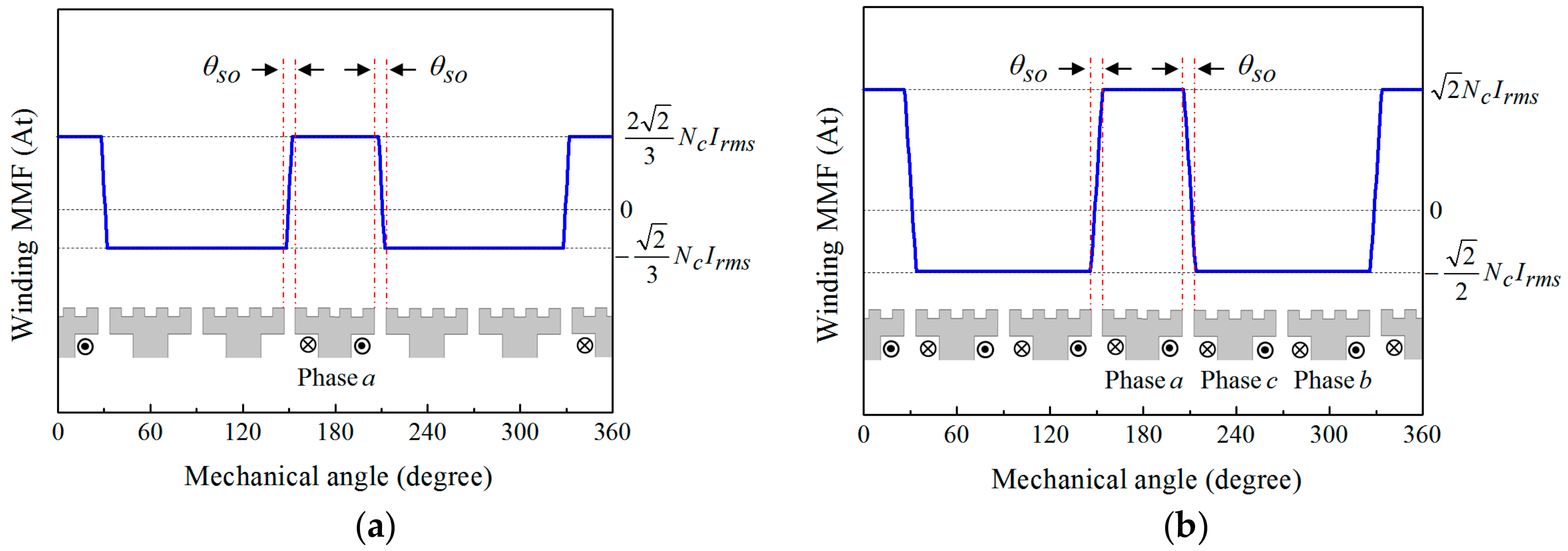
2.1. Winding MMF Function

The winding MMF is produced by current flowing through the armature windings and the MMF distribution in the air-gap can be obtained by following assumptions:
(1)
The flux density, MMF, and permeance in the air-gap are uniform with the axial direction.
(2)
The values of the winding MMF are varied linearly in the regions in front of the slot opening.
(3)
The three-phase currents are symmetric and sinusoidal as follows.
i a = 2 I r m s cos ( ω e t ) i b = 2 I r m s cos ( ω e t 2 π / 3 ) i c = 2 I r m s cos ( ω e t + 2 π / 3 )
where ωe is the electrical angular speed and Irms is a root mean square (RMS) value of the input current.
Using Ampere’s law in combination with Gauss’s law, the MMF distribution due to the a-phase winding is obtained as shown in Figure 2a. By using the Fourier analysis method, the MMF distribution can be expressed as follows [19].
f a ( θ m ) = m = 1 , 2 , 3 , F m a cos ( m p s θ m ) cos ( ω e t )
F m a = 4 2 N c I max m 2 p s θ s o π sin ( m π 3 ) sin ( m p s θ s o 2 )
where θm is the mechanical angle, θso is the mechanical angle of the slot opening, and Nc is the number of turns per coil.
The MMF distributions produced by the phase b and phase c can be found in the same manner. The total winding MMF distribution is calculated by the sum of each phase MMF. Figure 2b shows the MMF distribution due to the three-phase windings when the time is zero. In addition, the Fourier expression of the winding MMF distribution is given as follows.
F ( θ m , ω e t ) = m = 1 , 4 , 7 , F m cos ( m p s θ m ω e t ) + m = 2 , 5 , 8 , F m cos ( m p s θ m + ω e t )
F m = 6 2 N c I r m s m 2 p s θ s o π sin ( m π 3 ) sin ( m p s θ s o 2 )
where Fm is the Fourier coefficient for the (m × ps)th spatial harmonic of the total winding MMF distribution.

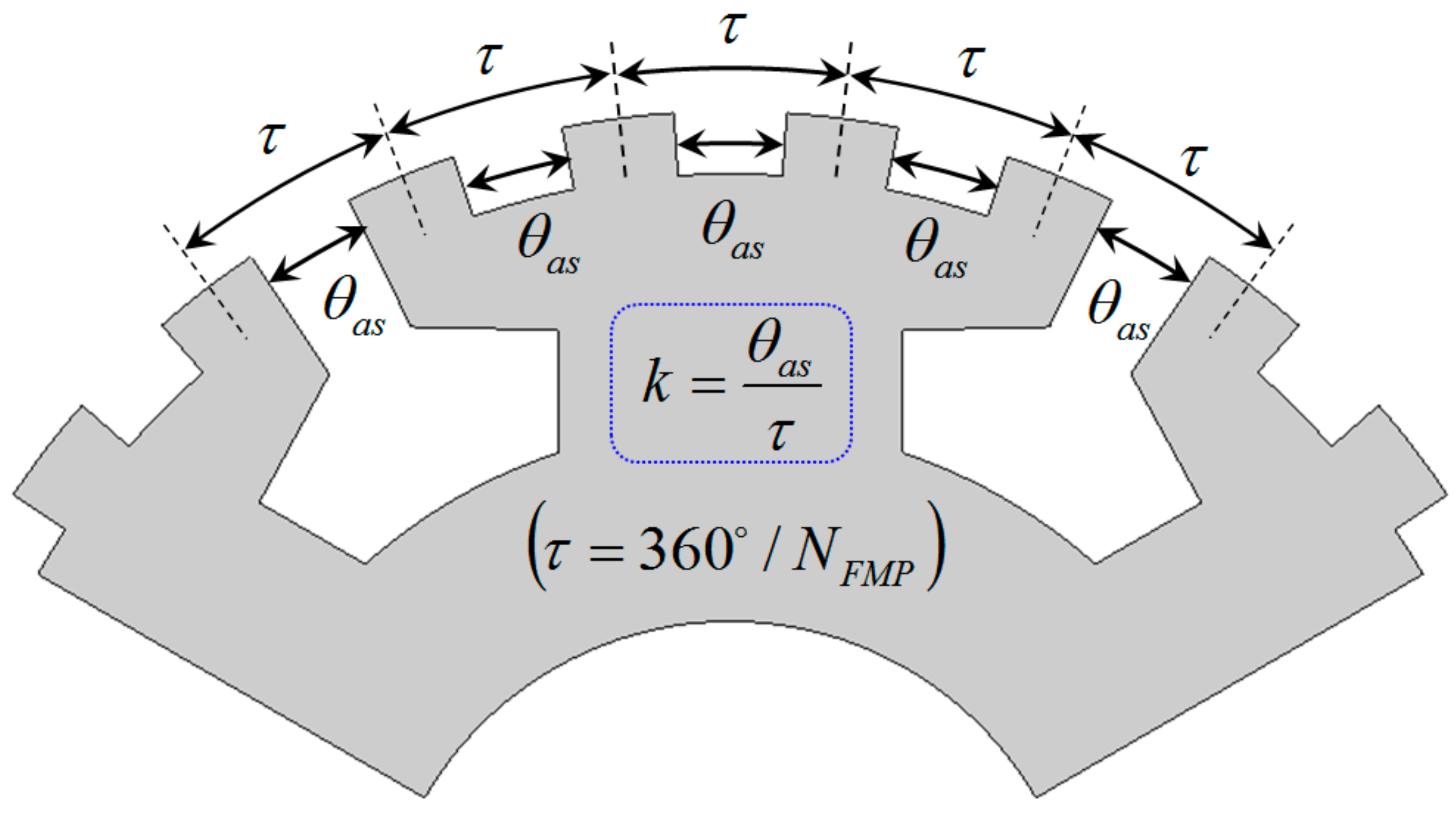
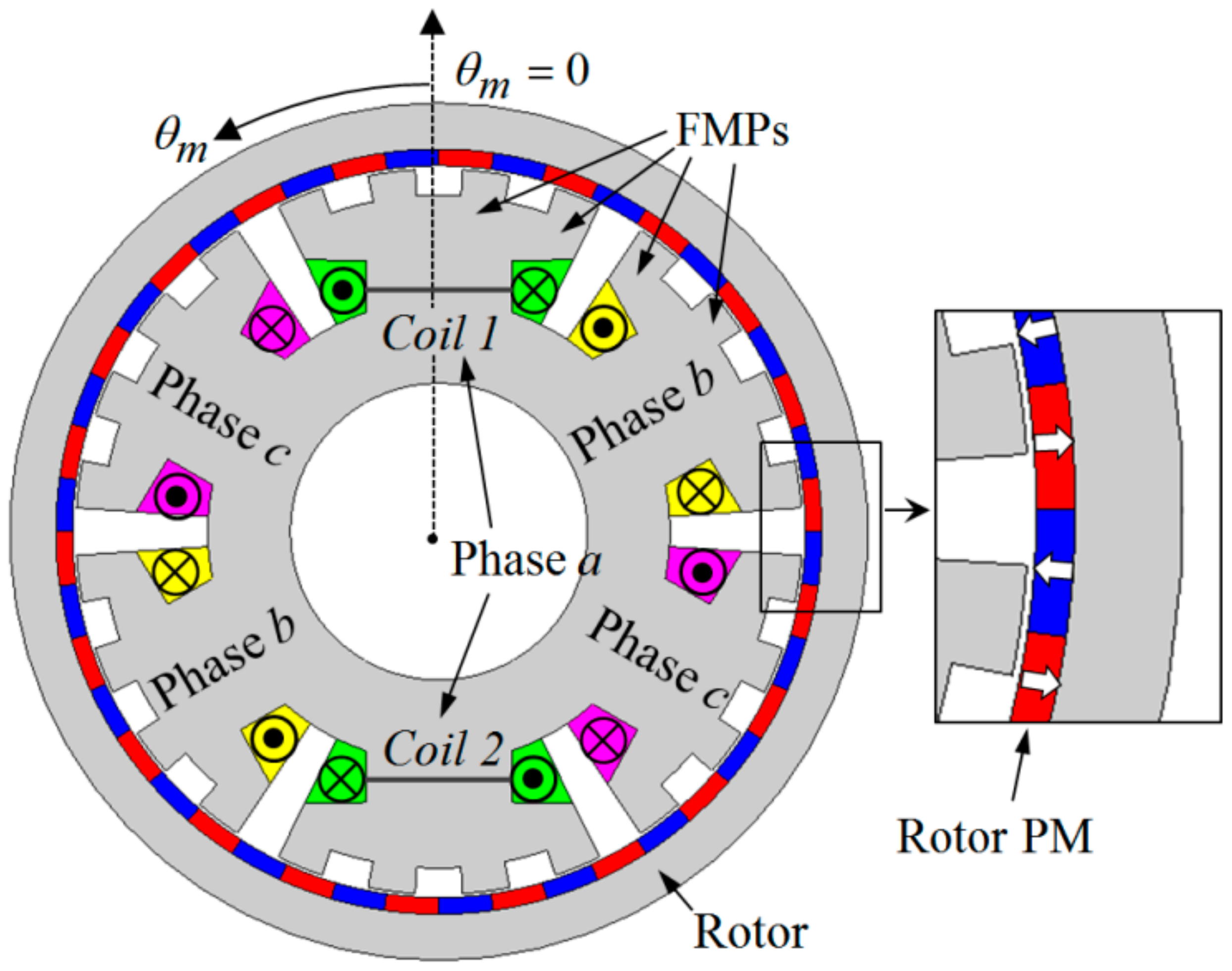
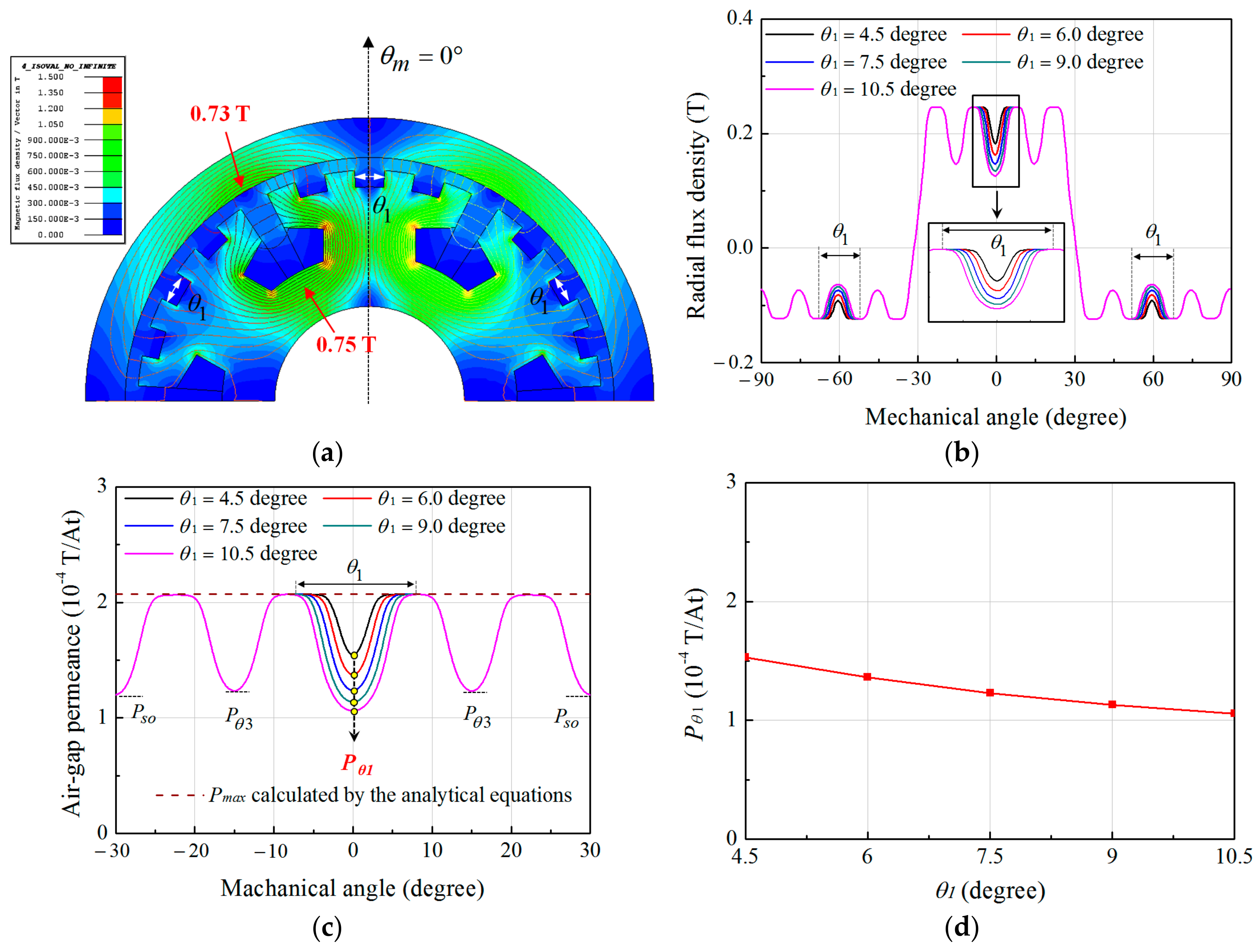
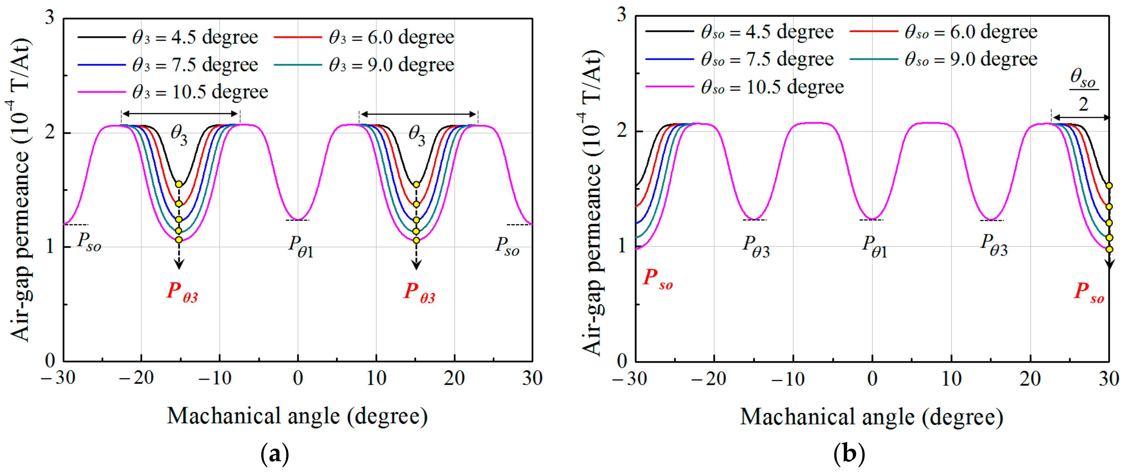
2.2. Air-Gap Permeance Function

To predict the air-gap permeance distribution, the following conditions are assumed:
(1)
The stator and rotor cores possess infinite permeability.
(2)
The relative permeability of the PM is unity.
(3)
FMPs formed on the tooth are in symmetry with respect to the central axis of the tooth.
(4)
All teeth are of the same shape.
(5)
The height of the FMPs is high enough to have no influence on the air-gap permeance distribution.
Figure 3 shows the FMP shapes formed on the tooth and the resulting distribution of the permeance in the air-gap. The permeance per unit area in the air-gap is determined by the length of the magnetic flux path, l as following [24].
P = μ 0 / l
where μ0 is the permeability of the air. On the regions of the air-gap in front of the FMPs, the length of the magnetic flux path is constant and the permeance has the maximum value, Pmax as shown in Figure 3a. On the contrary, the flux paths in front of the auxiliary slots and slot opening are varied along the circumferential direction due to the fringing flux. Due to the increased length of the flux path, the fringing flux decreases the values of the permeance. In addition, the distribution of the permeance caused by the fringing flux has symmetry in the regions between any two FMPs. Therefore, the air-gap permeance distribution in the regions of the auxiliary slots and slot opening can be approximated by using the second-order polynomial function as shown in Figure 3b. The analytical expression of the air-gap permeance over the region from 0 to π/6 radian can be expressed as follows.
P ( θ m ) = { P max , ( α 1 θ m α 2 , α 3 θ m α 4 ) A 1 θ m 2   + P θ 1 , ( 0 θ m α 1 ) A 2 ( θ m α 2 θ 3 / 2 ) 2 + P θ 3 , ( α 2 θ m α 3 ) A s o ( θ m α 4 θ s o / 2 ) 2 + P s o , ( α 4 θ m π / 6 )
{ A 1 = ( P max P θ 1 ) / ( θ 1 / 2 ) 2 A 2 = ( P max P θ 3 ) / ( θ 3 / 2 ) 2 A s o = ( P max P s o ) / ( θ s o / 2 ) 2
where Pθ1 and Pθ3 are the minimum values of the permeance in the auxiliary slots, and Pso is the minimum value of the permeance in the slot opening. Using the Fourier analysis and (8), the air-gap permeance function is expressed as follows.
P ( θ m ) = P 0 + j = 1 , 2 , 3 , P j cos ( j N s l o t θ m )
where the Nslot is the number of the slots, P0 is the DC offset value, and Pj is the Fourier coefficient for the (j × Nslot)th spatial harmonic of the air-gap permeance function. In addition, P0 and Pj are given as the functions of the design variables for the FMP shapes, θ1, θ2, θ3, θ4, and θso.
The harmonic characteristics of the air-gap permeance function depend on the dimensions of the design variables and the maximum and minimum values of the permeance. Based on (7), Pmax is equal to µ0/(lm + g), where, lm and g are the lengths of the PM and air-gap, respectively. In addition, Pmax is independent of the design variables as shown in Figure 3a. On the contrary, Pθ1, Pθ3, and Pso rely on θ1, θ3 and θso, respectively. If the path of the fringing flux is assumed to take circular trajectories, the minimum values of the permeance in the regions in which the fringing flux exist can be predicted [22]. However, this approach has errors in the amplitudes of the harmonics of the air-gap permeance function. Particularly, the amount of errors changes with the variations of θ1, θ3, and θso. Hence, for the high accuracy of the air-gap permeance function, the variations of Pθ1, Pθ3 and Pso according to θ1, θ3 and θso are analyzed by using the FEA method. Then, the variations of Pθ1, Pθ3, and Pso are expressed as functions of the design variables by using the least-square method and the resulting functions are employed in (8) and (9).
Under the conditions of the time equal zero and the RMS value of the phase current at 6A, the radial flux density distribution in the air-gap caused by the armature windings is obtained by using the commercial software, Cedrat FLUX 2-D. In addition, the winding MMF distribution is calculated by (5) and (6) under the same condition with the FEA. The air-gap permeance function can be taken as [19].
P ( θ m ) = B ( θ m , ω e t ) / F ( θ m , ω e t )
Figure 4 shows the radial flux density distributions in the air-gap due to the armature windings and the corresponding permeance distributions according to θ1. As shown in Figure 4a, the maximum values of the flux density in the stator and rotor yoke are 0.75 T and 0.73 T, respectively. It indicates that the stator and rotor cores are not saturated by the magnetic flux due to the winding MMF. Hence, Pmax calculated by the analytical equation assuming the infinite permeability of the cores has a similar value with that obtained from the FEA method, which considers the non-linear characteristics of the core material, as shown in Figure 4c. Since the winding MMF distribution is the same, it can be found that the variations of the radial flux density distributions according to θ1 result from the changes of the air-gap permeance distributions. As shown in Figure 4c,d, the increase of θ1 tends to decrease the value of Pθ1 but has no influence on Pmax, Pθ3, and Pso. Hence, Pθ1 can be expressed as the function of θ1 by using the least-square method. In the same manner, the variations of Pθ3 and Pso according to θ3 and θso respectively can be obtained as shown in Figure 5. From the analysis results, Pθ1, Pθ3, and Pso are given as follows.
P θ v = ( 2.22 10.57 × θ v + 23.19 × θ v 2 ) × 10 4 ,   ( v = 1 ,   3 )
P θ s o = ( 2.20 10.03 × θ s o + 18.56 × θ s o 2 ) × 10 4
where θ1, θ3, and θso are the angles in radians. By substituting (12) and (13) into (8) and (9), the harmonic characteristics of the permeance in the air-gap permeance function, which changes with the design variables of the FMP shape can be predicted accurately.

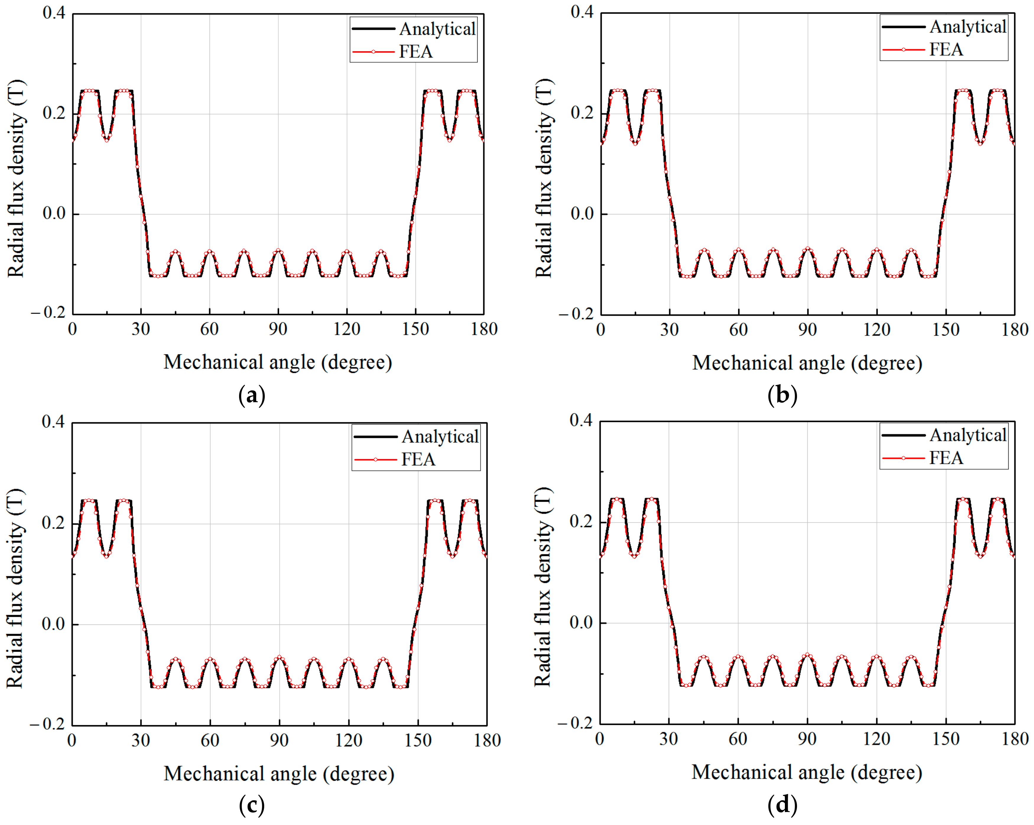
2.3. Flux Density Distribution by the Windings

By multiplying (5) and (10), the radial flux density distribution in the air-gap due to the armature windings is given as:
B ( θ m , ω e t ) = P 0 m = 1 , 4 , 7 , F m cos ( m p s ( θ m ω e m p s t ) )   + P 0 m = 2 , 5 , 8 , F m cos ( m p s ( θ m + ω e m p s t ) ) + m = 1 , 4 , 7 , j = 1 , 2 , 3 , F m P j 2 cos ( ( m p s + j N s l o t ) ( θ m ω e m p s + j N s l o t t ) ) + m = 2 , 5 , 8 , j = 1 , 2 , 3 , F m P j 2 cos ( ( m p s + j N s l o t ) ( θ m + ω e m p s + j N s l o t t ) ) + m = 1 , 4 , 7 , j = 1 , 2 , 3 , F m P j 2 cos ( ( m p s j N s l o t ) ( θ m ω e m p s j N s l o t t ) ) + m = 2 , 5 , 8 , j = 1 , 2 , 3 , F m P j 2 cos ( ( m p s j N s l o t ) ( θ m + ω e m p s j N s l o t t ) )
In the SPMV machine, as shown in Figure 1, the working harmonic of the air-gap flux density distribution due to the armature windings is the 22nd spatial harmonic which corresponds to the number of the rotor pole pairs, and it can be arranged as followings.
B 22 nd ( θ m , ω e t ) = B 22   cos ( 22 θ m + ω e t )
B 22 = [ F 11 P 0 + 0.5 × ( F 1 P 4 + F 2 P 3 + F 4 P 5 + F 5 P 2 + F 7 P 6 + F 8 P 1 + F 10 P 7 + ) ]
where Fm is the Fourier coefficient for the (m × ps)th spatial harmonic of the winding MMF distribution and Pj is the Fourier coefficient for the (j × Nslot)th spatial harmonic of the air-gap permeance function. In this paper, ps and Nslot are 2 and 6, respectively. It is seen that all the winding MMF harmonics can affect the magnitude of the working harmonic according to harmonic characteristics of the air-gap permeance function. Since Fm and Pj are expressed as the functions of the design variables for the FMP shape, the dimensions for the design variables to maximize the working harmonic can be obtained from (16) without the FEA.

2.4. Flux Density Distribution by the Windings

In general, the FMP pitch, τ, is constant and the widths of the auxiliary slots, θas, including the slot openings are changed identically as shown in Figure 6. In addition, the slot width ratio, k, which is a ratio of the auxiliary slot width to the FMP pitch, is selected as a design parameter. To verify the accuracy and validity of the analytical model, the magnetic fields due to the armature windings are analyzed according to the slot width ratio by using the analytical model and the FEA. Table 2 shows the dimensions of the design variables shown in Figure 3 according to k, where θ1, θ3, and θso are equal to k × τ, and θ2 and θ4 are equal to (1 − k) × τ. Figure 7 shows the radial flux density distributions in the air-gap due to the armature winding according to the slot width ratio when the RMS value of the input current is 6A and time is zero. The FEA results for the flux density distribution are in good agreement with the results obtained by the analytical model.
Figure 8 compares the characteristics of the output torque and air-gap permeance that are predicted by the FEA according to the slot width ratio, k. In the SPMV machine, the output torque is generated by the interaction between the 22nd spatial harmonics of the air-gap flux density produced by the stator windings and the rotor PMs. Thus, under the condition of the same rotor, the average torque is proportional to the amplitude of the working harmonic, which is the 22nd spatial harmonic due to the windings, as shown in Figure 8a. In addition, the torque ripple in the SPMV machine has a similar trend with the cogging torque as shown in Figure 8b. The changes of the working harmonic according to k can be explained by analyzing the harmonic characteristics of the air-gap permeance function as shown in Figure 8c. Regardless of k, the permeance functions consist of the DC offset value, P0 and the spatial harmonics of the orders corresponding to multiples of 24. Based on (16), both P0 and the 24th spatial harmonic of the permeance can affect the working harmonic. However, the rise of k increases the 24th spatial harmonic but decreases P0. Consequently, when k = 0.6, the working harmonic and the output torque are maximized and are improved by 3.9% and 3.7%, respectively.

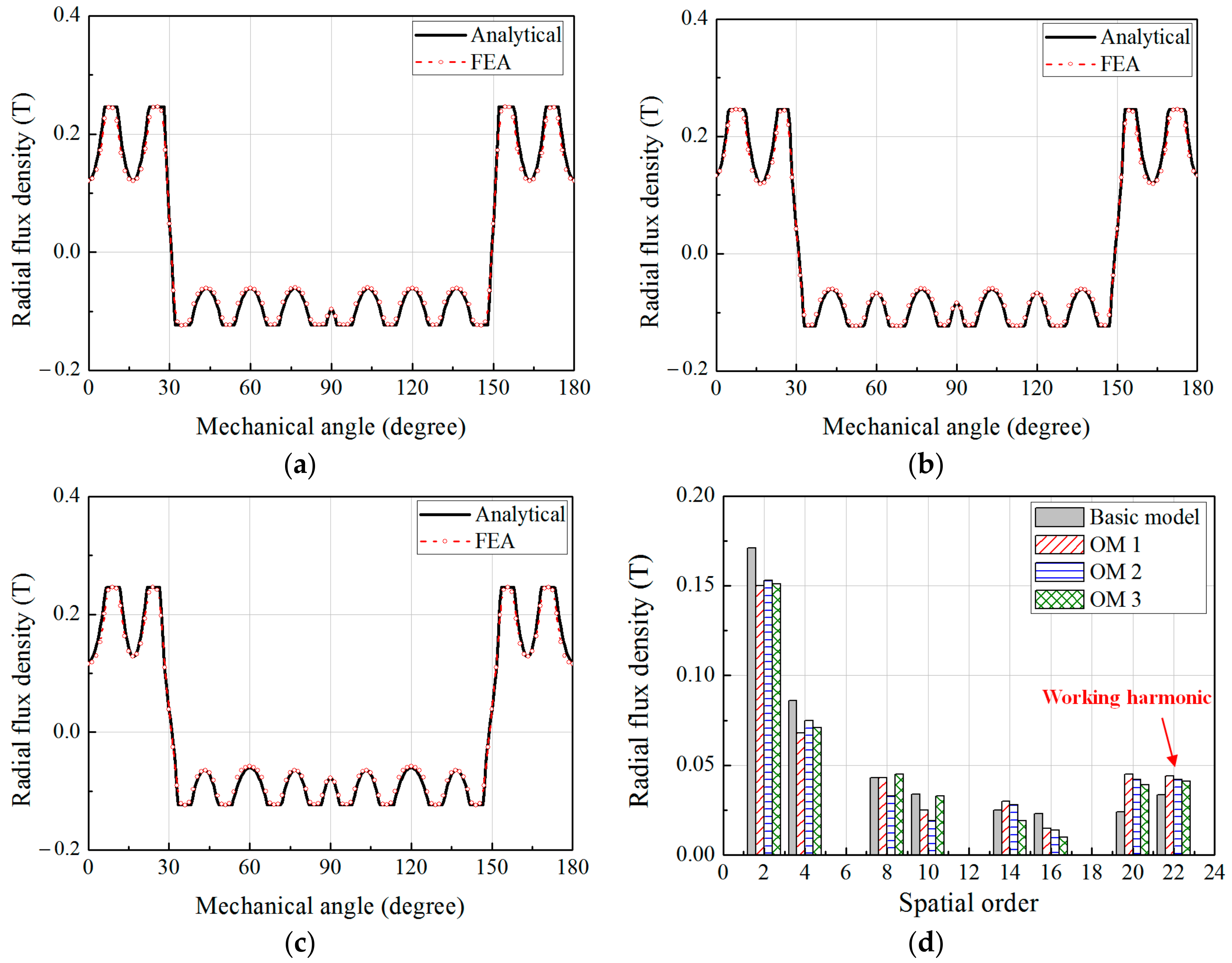
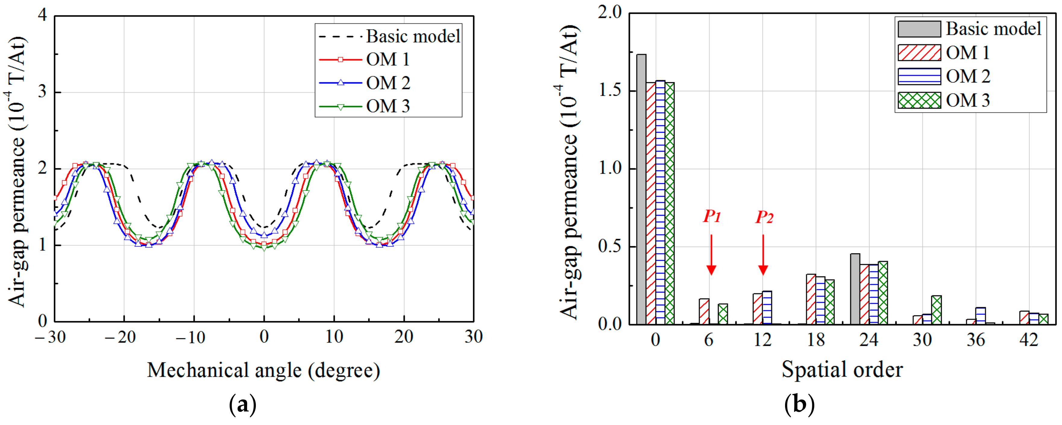
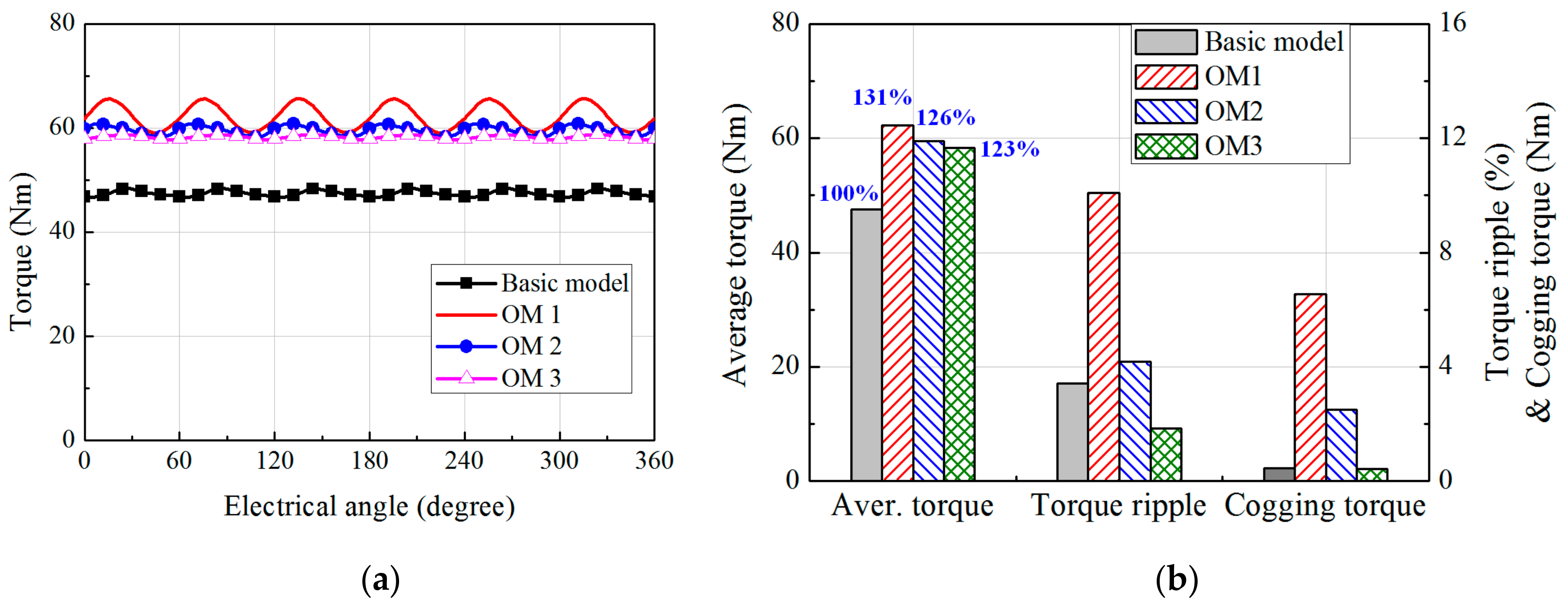
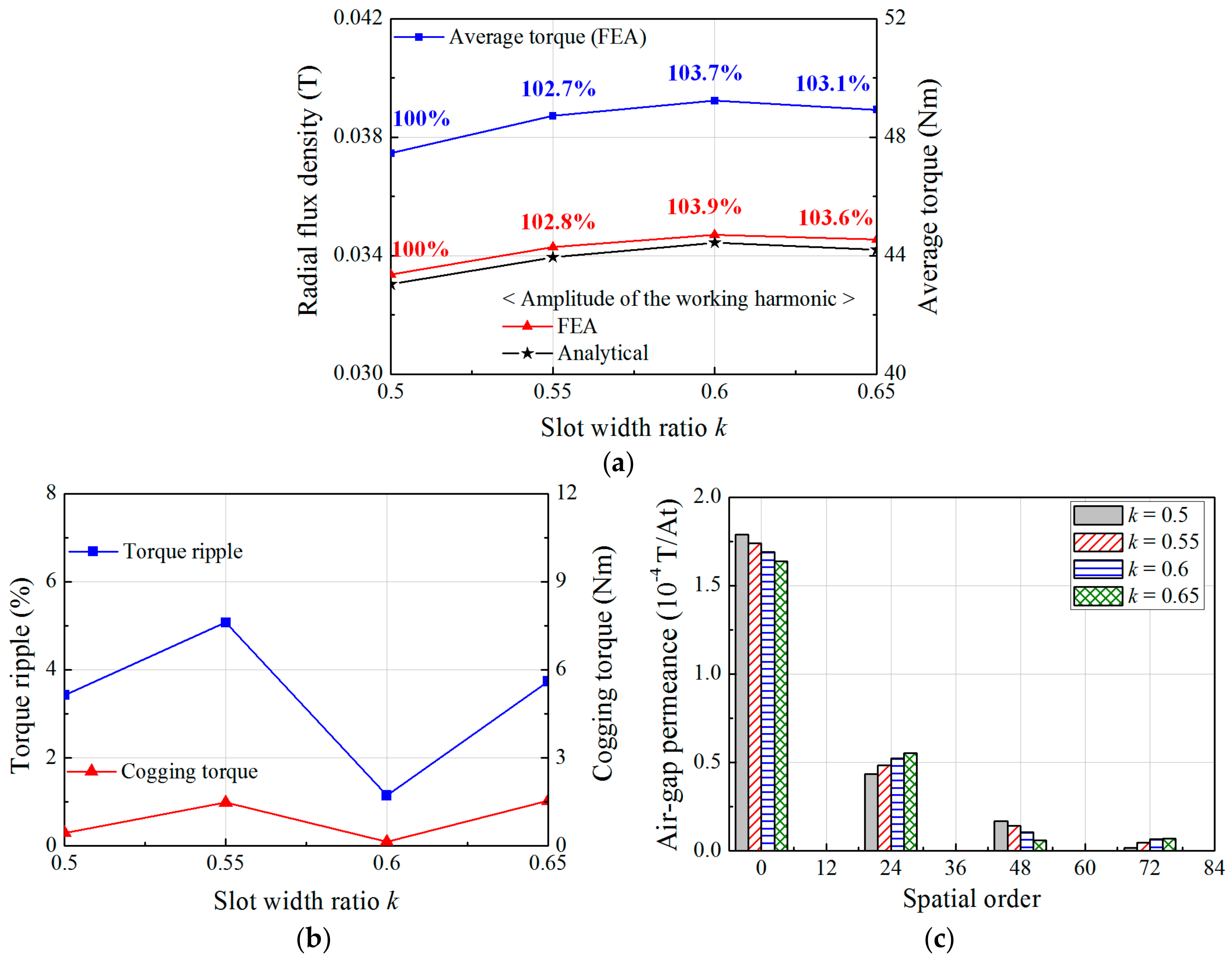
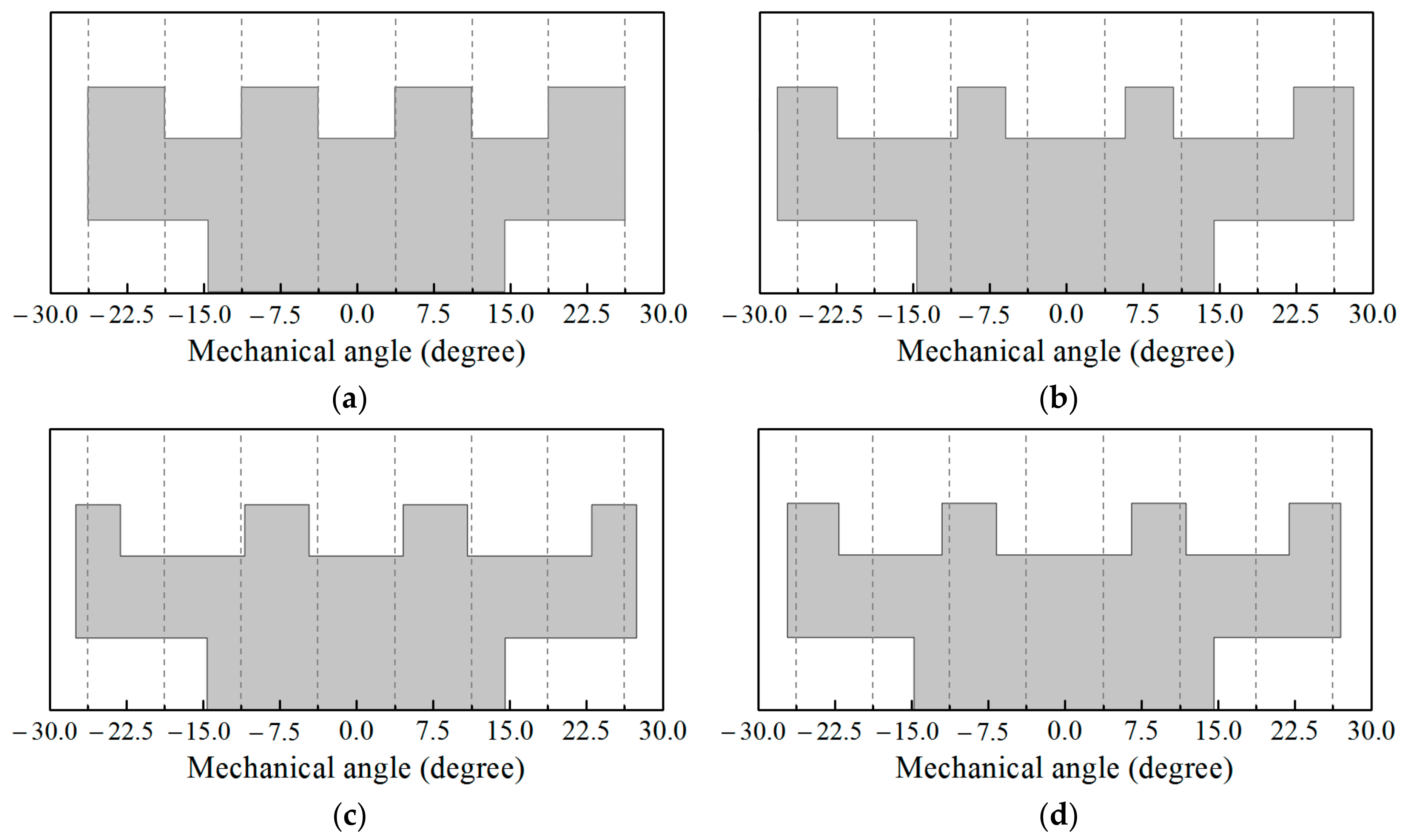
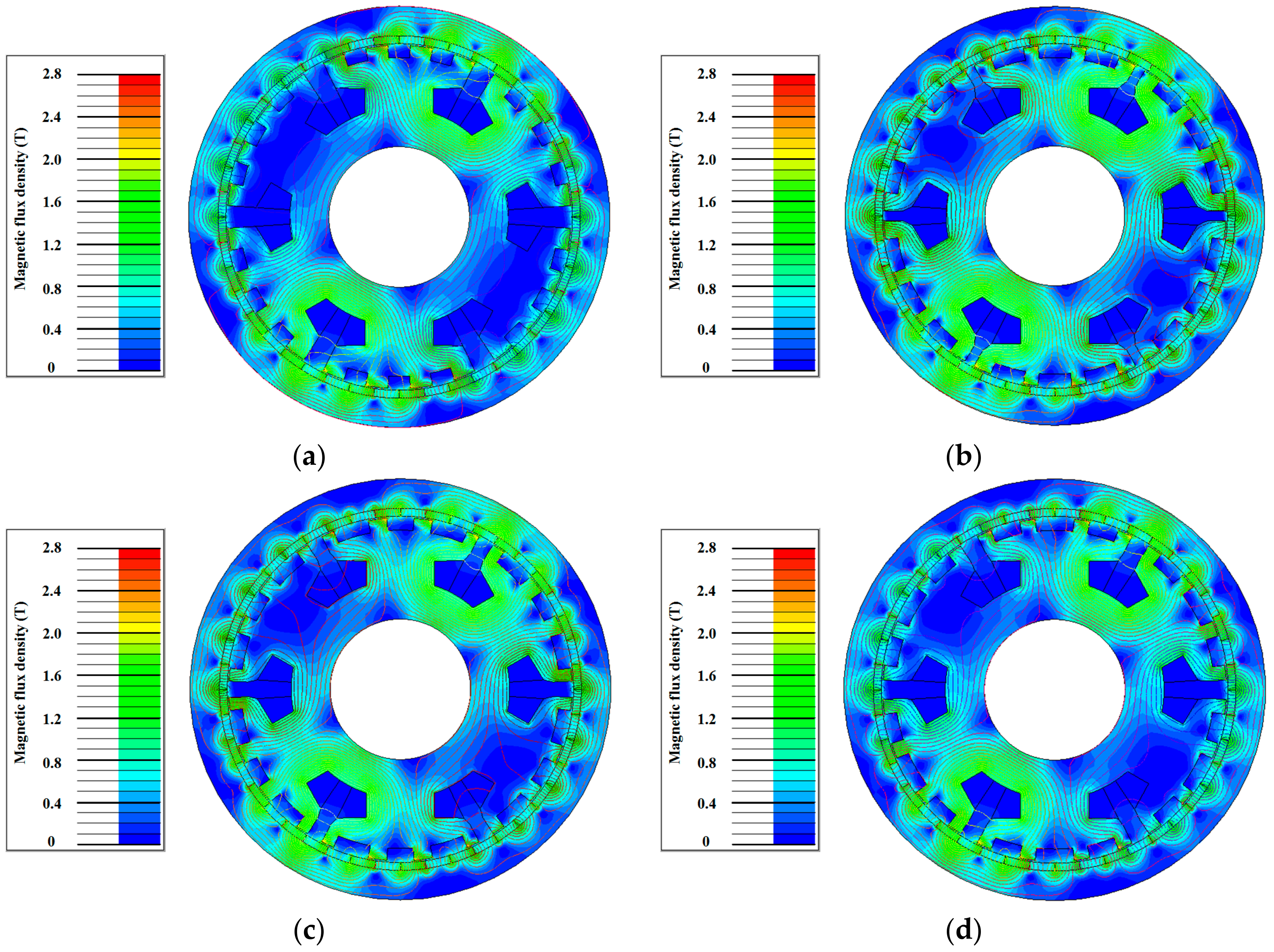
3. Optimization of the FMP Shape

The output torque of the SPMV machine is proportional to the working harmonic. Thus, the optimal combination of the design variables to maximize the output torque and the working harmonic can be obtained by using (16). To carry out the optimization, the genetic algorithm toolbox in MATLAB is applied. A design optimization problem can be formulated to maximize the working harmonic in (17) as follows.
Maximize   | B 22 ( x ) |
where x is a set of the design variables as shown in Figure 3. To consider the characteristics of the torque ripple, the three constraint conditions for the harmonic component of the air-gap permeance function are applied for the three optimal models (OM) as following, respectively.
Subject   to Nothing for   Optimal   model   1   ( OM 1 ) P 1 ( x )   =   0 for   Optimal   model   2   ( OM 2 ) P 2 ( x )   =   0 for   Optimal   model   3   ( OM 3 )
where P1(x) and P2(x) are the Fourier coefficients for the 6th and 12th spatial harmonics of the air-gap permeance function, respectively. In Section 2, it is found that the torque ripple of the SPMV machine is affected significantly by the cogging torque, which is varied according to the FMP shapes. When the FMPs are designed by adjusting the slot width ratio, the air-gap permeance function consists of the spatial harmonics of the multiples of NFMP. In this case, the torque ripple and cogging torque are low and their characteristics are similar to that of the basic model in which the slot width ratio is 1. However, the Fourier expression, (9) of the air-gap permeance function derived in this paper includes the spatial harmonics lower than NFMP that can increase the cogging torque such as the 6th, 12th, and 18th spatial harmonics. In (16), the 18th spatial harmonic of the air-gap permeance can considerably produce the working harmonic and output torque by interacting with the 4th spatial harmonic of the winding MMF which has second highest amplitude. In contrast, the effects of the 6th and 12th spatial harmonics on the working harmonic are relatively low. Thus, the 6th and 12th harmonics of the permeance can be regulated to reduce the torque ripple in the optimization, while improving the output torque. The constraint conditions in (18) are to reduce the cogging torque and torque ripple by removing the effects of P1(x) and P2(x) in the OM2 and OM3, respectively.
Table 3 gives the optimization results and Figure 9 shows the geometries of the FMPs for the basic and optimal models. Compared with the basic model, the working harmonics in the OM1, OM2, and OM3 are increased by 32%, 27%, and 24%, respectively. Figure 10 compares the radial flux density distribution due to the windings obtained by the analytical and FEA methods. It shows good agreement between the FEA and analytical methods. Figure 11 shows the air-gap permeance distribution for the basic and optimal models calculated by the FEA. In both methods of the analytical and FEA, the air-gap permeance functions of the OM2 and OM3 contain no spatial harmonics of the 6th and 12th, respectively. It indicates that the analytical model can accurately regulate the amplitude of the specific harmonics of the air-gap permeance in the optimization process.
The generated torque and cogging torque of the SPMV machine are calculated using 2D FEA. The same structure of the rotor is applied to the basic and optimal models. Figure 12 shows the flux density distributions obtained from the FEA for the analysis models. Although the working harmonics of the optimal models are improved over 20% compared with the basic model, the flux density distributions of the stator and rotor yokes in all models have a similar tendency under the load condition. Figure 13 shows the torque characteristics. When compared with the basic model, the average torque of the optimal models increases at the similar ratio with the increases of the working harmonics as shown in Table 3. In addition, it can be seen that the torque ripple has a similar trend with the cogging torque. In OM1, the working harmonic and average torque are the maximum, but the torque ripple increased up to 10%. Compared with the OM1, the cogging torque and torque ripple in the OM2 and OM3 are reduced by excluding the 6th and 12th spatial harmonics of the permeance function, respectively. In particular, when the 12th spatial harmonic of the permeance function is eliminated in the OM3, the cogging torque has a similar value with that of the basic model as shown in Figure 13. As the results, in the OM3, the torque ripple has a minimum value as 1.83%. Figure 14 shows the characteristics of the back electro motive force (EMF) for the basic and optimal models when the rotating speed of the rotor is 500 rpm. The total harmonic distortion of the back EMF has a lower value than 2% for all models. In addition, compared with the basic model, the fundamentals of the back EMF waveforms for the optimal models are improved at a similar percentage with the increase of the output torque.

4. Conclusions

This paper presents a novel method to design the FMP shape of the SPMV machine by using analytical equations for the flux density distribution in the air-gap due to the armature windings. The analytical expressions for the winding MMF, permeance and flux density distributions in the air-gap are derived by using the Fourier analysis technique. In addition, for the high accuracy of the analytical method, the air-gap permeance function is modeled to be changed with the design variables by using the FEA and least-square methods. Using the analytical equation and genetic algorithm, the FMP shape is optimized to maximize the working harmonic of the armature magnetic field that generates the output torque. Thus, the proposed method enables the FMP shape to be designed by the optimal combination of the air-gap permeance harmonic components which is determined in the analytical equation without the FEA method. The optimal FMP shape developed by the proposed method can improve the average torque by increasing the working harmonic. The FEA results show that the increase ratio of the working harmonic is similar to that of the output torque. In addition, the torque ripple can be reduced by eliminating the specific spatial harmonic of the permeance function, which affects the cogging torque, in the analytical expressions during the optimization process. Although several FEA simulations are carried out to define the air-gap permeance function in the proposed method, the number of simulations required is considerably less than that in the conventional optimal method using the FEA method. Thus, the proposed method can save the time for the optimal design of the FMP.

Acknowledgments

This research was supported by the Korea Institute of Energy Technology Evaluation and Planning (KETEP) and the Ministry of Trade, the Industry and Energy (MOTIE) of the Republic of Korea (No. 20152020000750); and the Basic Science Research Program through the National Research Foundation (NRF) of Korea funded by the Ministry of Education (NRF-2015R1D1A1A01059637).

Author Contributions

All authors have contributed to this work. Daekyu Jang was the main author of this manuscript and contributed to the theoretical analysis, modeling, simulation, and manuscript preparation. Junghwan Chang provided technical guidance for research work and supervised the whole project.

Conflicts of Interest

The authors declare no conflict of interest.

References

  1. Li, X.; Chau, K.T.; Cheng, M. Analysis, design and experimental verification of a field-modulated permanent-magnet machine for direct-drive wind turbines. IET Electr. Power Appl. 2015, 9, 150–159. [Google Scholar] [CrossRef]
  2. Gao, Y.; Qu, R.; Li, D.; Li, J.; Zhou, G. Design of a dual-stator LTS vernier machine for direct-drive wind power generation. IEEE Trans. Appl. Supercond. 2016, 26. [Google Scholar] [CrossRef]
  3. Liu, Y.; Ho, S.L.; Fu, W.N.; Zhang, X. Design optimization of a novel doubly fed dual-rotor flux-modulated machine for hybrid electric vehicles. IEEE Trans. Magn. 2015, 51, 1–4. [Google Scholar] [CrossRef]
  4. Liu, G.; Yang, J.; Zhao, W.; Ji, J.; Chen, Q.; Gong, W. Design and analysis of a new fault-tolerant permanent-magnet vernier machine for electric vehicles. IEEE Trans. Magn. 2012, 48, 4176–4179. [Google Scholar] [CrossRef]
  5. Jia, S.; Qu, R.; Li, D.; Li, J. A high torque density vernier PM machines for hybrid electric vehicle applications. In Proceedings of the 2016 IEEE Vehicle Power and Propulsion Conference (VPPC), Hangzhou, China, 17–20 October 2016. [Google Scholar] [CrossRef]
  6. Nakata, Y.; Ishiguro, H.; Kitani, K.; Fujimoto, T.; Hirata, K. Development and control of a novel cylindrical IPM linear vernier motor for compliant robot actuation. In Proceedings of the 2013 IECON—39th Annual Conference of the IEEE Industrial Electronics Society, Vienna, Austria, 10–13 November 2013. [Google Scholar] [CrossRef]
  7. Du, Z.S.; Lipo, T.A. Torque performance comparison between a ferrite magnet vernier motor and an industrial interior permanent magnet machine. IEEE Trans. Ind. Appl. 2017, 53, 2088–2097. [Google Scholar] [CrossRef]
  8. Vukotić, M.; Miljavec, D. Design of a permanent-magnet flux-modulated machine with a high torque density and high power factor. IET Electr. Power Appl. 2016, 10, 36–44. [Google Scholar] [CrossRef]
  9. Li, D.; Qu, R.; Li, J.; Xiao, L.; Wu, L.; Xu, W. Analysis of torque capability and quality in vernier permanent-magnet machines. IEEE Trans. Ind. Appl. 2016, 52, 125–135. [Google Scholar] [CrossRef]
  10. Okada, K.; Niguchi, N.; Hirata, K. Analysis of a vernier motor with concentrated windings. IEEE Trans. Magn. 2013, 49, 2241–2244. [Google Scholar] [CrossRef]
  11. Xu, L.; Liu, G.; Zhao, W.; Yang, X.; Cheng, R. Hybrid stator design of fault-tolerant permanent-magnet vernier machines for direct-drive applications. IEEE Trans. Ind. Appl. 2017, 64, 179–190. [Google Scholar] [CrossRef]
  12. Toba, A.; Lipo, T.A. Generic torque-maximizing design methodology of surface permanent-magnet vernier machine. IEEE Trans. Ind. Appl. 2000, 36, 1539–1546. [Google Scholar] [CrossRef]
  13. Du, Y.; Cheng, M.; Chau, K.T.; Liu, X.; Xiao, F.; Zhao, W. Linear primary permanent magnet vernier machine for wave energy conversion. IET Electr. Power Appl. 2015, 9, 203–212. [Google Scholar] [CrossRef]
  14. Jang, D.; Chang, J. Design of a vernier machine with PM on both sides of rotor and stator. IEEE Trans. Magn. 2014, 50, 877–880. [Google Scholar] [CrossRef]
  15. Li, D.; Qu, R.; Xu, W.; Li, J.; Lipo, T.A. Design procedure of dual-stator spoke-array vernier permanent-magnet machines. IEEE Trans. Ind. Appl. 2015, 51, 2972–2983. [Google Scholar] [CrossRef]
  16. Wang, Q.; Niu, S.; Ho, S.L.; Fu, W.; Zuo, S. Design and analysis of novel magnetic flux-modulated mnemonic machines. IET Electr. Power Appl 2015, 9, 469–477. [Google Scholar] [CrossRef]
  17. Xu, L.; Liu, G.; Zhao, W.; Ji, J.; Zhou, H.; Zhao, W.; Jiang, T. Quantitative comparison of integral and fractional slot permanent magnet vernier motors. IEEE Trans. Energy Convers. 2015, 30, 1483–1495. [Google Scholar] [CrossRef]
  18. Kim, B.; Lipo, T.A. Analysis of a PM vernier motor with spoke structure. IEEE Trans. Ind. Appl. 2016, 52, 217–225. [Google Scholar] [CrossRef]
  19. Jang, D.; Chang, J. Influences of winding MMF harmonics on torque characteristics in surface-mounted permanent magnet vernier machines. Energies 2017, 10, 580. [Google Scholar] [CrossRef]
  20. Jang, D.; Chang, J. Effects of flux modulation poles on the radial magnetic forces in surface-mounted permanent magnet vernier machines. IEEE Trans. Magn. 2017, 53. [Google Scholar] [CrossRef]
  21. Zou, T.; Li, D.; Qu, R.; Jiang, D.; Li, J. Advanced high torque density PM vernier machine with multi working harmonics. IEEE Trans. Ind. Appl. 2017. [Google Scholar] [CrossRef]
  22. López Torres, C.; Garcia, A.; Riba, J.; Romeral, L. Design and optimization for vehicle driving cycle of rare-earth-free SynRM based on coupled lumped thermal and magnetic networks. IEEE Trans. Veh. Technol. 2017. [Google Scholar] [CrossRef]
  23. Zhao, W.; Kwon, J.; Wang, X.; Lipo, T.A.; Kwon, B. Optimal design of a spoke-type permanent magnet motor with phase-group concentrated-coil windings to minimize torque pulsations. IEEE Trans. Magn. 2017, 53. [Google Scholar] [CrossRef]
  24. Zhu, Z.Q.; Howe, D. Instantaneous magnetic field distribution in brushless permanent magnet dc motors. III. Effect of stator slotting. IEEE Trans. Magn. 1993, 29, 143–151. [Google Scholar] [CrossRef]
Figure 1. A structure of the surface-mounted permanent magnet vernier (SPMV) machine with non-overlapping windings.
Energies 10 01551 g001
Figure 2. The magneto-motive force (MMF) distributions when the time is zero. (a) Due to the a-phase winding; (b) due to the three-phase windings.
Energies 10 01551 g002
Figure 3. The shape of the flux modulation poles (FMPs) formed on the tooth and the resulting permeance in the air-gap. (a) Design variables for the FMP shape; (b) Air-gap permeance distribution.
Energies 10 01551 g003
Figure 4. Radial flux density distributions in the air-gap due to the armature windings and the corresponding permeance distributions according to θ1. (a) Flux density distribution when θ1 = 7.5 degree; (b) Radial flux density distributions; (c) Air-gap permeance distributions; (d) Variations of Pθ1.
Energies 10 01551 g004
Figure 5. Air-gap permeance distribution. (a) According to θ3; (b) According to θso.
Energies 10 01551 g005
Figure 6. FMP pitch and the width of the auxiliary slots including the slot openings.
Energies 10 01551 g006
Figure 7. Radial flux density distributions in the air-gap due to the armature windings according to slot width ratio, k. (a) k = 0.5; (b) k = 0.55; (c) k = 0.6; (d) k = 0.65.
Energies 10 01551 g007
Figure 8. Characteristics of the output torque and air-gap permeance according to the slot width ratio, k. (a) Average torque and working harmonic; (b) Torque ripple and cogging torque; (c) Harmonic components of the air-gap permeance functions.
Energies 10 01551 g008
Figure 9. Geometries of the FMPs for the basic and optimal models. (a) Basic model; (b) OM1; (c) OM2; (d) OM3.
Energies 10 01551 g009
Figure 10. Flux density distributions in the air-gap due to the armature windings in the optimal models. (a) OM1; (b) OM; (c) OM3; (d) Harmonic components.
Energies 10 01551 g010
Figure 11. Air-gap permeance in the basic and optimal models. (a) Distributions; (b) Harmonic components.
Energies 10 01551 g011
Figure 12. Flux density distributions for the basic and optimal models under load condition. (a) Basic model; (b) OM1; (c) OM2; (d) OM3.
Energies 10 01551 g012
Figure 13. Torque characteristics of the basic and optimal models. (a) Waveforms; (b) Torque characteristics.
Energies 10 01551 g013
Figure 14. Back electro motive force (EMF) characteristics of the basic and optimal models. (a) Waveforms; (b) Harmonic components.
Energies 10 01551 g014
Table 1. Design specifications.
QuantityValueQuantityValue
Rotor Outer Diameter260 mmHeight of FMPs8 mm
Stack Length30 mmNumber of turns per coil140
Air-Gap Length1 mmPM residual flux density1.2 T
PM Thickness5 mmArmature phase current6 A
Table 2. Dimensions of the design variables according to the slot width ratio, k.
Slot Width RatioDesign Variables (°)
kθ1θ2θ3θ4θs
0.57.57.57.57.57.5
0.558.256.758.256.758.25
0.696969
0.659.755.259.755.259.75
Table 3. Optimization results.
ModelDesign Variables (Degree)|B22(x)| (T)
θ1θ2θ3θ4θsAnalyticalFEA
Basic Model7.57.57.57.57.50.0340.033
OM111.664.711.725.863.780.0450.044
OM29.176.2512.094.355.450.0430.042
OM313.065.279.974.986.490.0420.041

