Article

Influence of Refrigerant Charge Amount and EEV Opening on the Performance of a Transcritical CO2 Heat Pump Water Heater

1
State Key Laboratory of Multiphase Flow in Power Engineering, Xi’an Jiaotong University, Xi’an 710049, China
2
Allfavor Circuits (Shenzhen) Co. Ltd., Shenzhen 518105, China
3
Xi’an Jiaotong University Suzhou Academy, Suzhou 215123, China
*
Author to whom correspondence should be addressed.
Energies 2017, 10(10), 1521; https://doi.org/10.3390/en10101521
Submission received: 30 July 2017 / Revised: 20 September 2017 / Accepted: 26 September 2017 / Published: 3 October 2017
(This article belongs to the Section I: Energy Fundamentals and Conversion)

Abstract

:
Besides compressor rotary speed and parameters of water flowing through gas cooler and evaporator, refrigerant charge amount and electronic expansion valve (EEV) opening are two important parameters that have significant effects on the performance of a transcritical CO2 heat pump system. In this study, the effects of refrigerant charge amount on the performance of a transcritical CO2 heat pump water heater were investigated experimentally at different EEV openings. An optimal coefficient of performance (COP) was found that corresponded to a specific refrigerant charge and a specific EEV opening. Based on the experiment, the COP peaked at charge of 1.8 kg when EEV opening was 40% of full opening. The heating capacity and the COP increased at first, reached peaks and then decreased with increase of charge amount. The COP decreased 14.95% as the CO2 charge amount was reduced by 22.2% from the optimal charge at 50% EEV opening. As EEV opening varied from 40% to 60% at the same charge amount, the heating capacity decreased more than 30%.

1. Introduction

Since chlorofluorocarbon (CFC) and hydro-chlorofluorocarbons (HCFC) were restricted because of the environmental issues, researchers are working on feasible and effective alternative refrigerants. Substantially, carbon dioxide (CO2, R744) is one of the representatives [1,2]. Owing to some properties such as zero ozone depletion potential (ODP), negligible global warming potential (GWP), excellent heat transfer properties, high volumetric capacity and cheap price, carbon dioxide has been widely acknowledged as the most competitive alternative refrigerant. In 1993, a CO2 transcritical refrigeration system in automotive air conditioning was built and tested [3]. As time goes on, CO2 transcritical refrigeration technology is wildly applied in vehicles [4], water heaters [5,6], heat pumps [6,7] and low temperature cascade refrigeration systems [8], and so on.
The coefficient of performance (COP) of a heat pump system is affected by many factors. The amount of refrigerant charge of the system is a primary parameter that influences the energy efficiency. Undercharge or overcharge of refrigerant degrade its performance and deteriorates the system reliability. The electronic expansion valve (EEV) opening is another important parameter that needs to optimize. Therefore, in order to achieve the optimum COP, an appropriate refrigerant charge amount corresponding to a specific EEV opening is important for a heat pump water heater. However, it is difficult to calculate the optimal charge accurately because of the various components and operating parameters. In recent years, research on the lubricating oil, compressor, heat exchanger structure design, the flow and heat transfer performance, and system design have made great progress. But investigations about the influence of the refrigerant charge amount and EEV opening on the performance of transcritical CO2 heat pump systems are limited.
Though the phenomenon that system performance is affected by refrigerant charge has been well known, the method of calculating the optimal refrigerant charge is not well developed. Some mathematical models and evaluating methods have been reported. Zhang et al. [9] conducted simulation works on the effects of refrigerant charge and structural parameters on the performance of a direct-expansion solar-assisted heat pump system. Vjacheslav et al. [10] proposed a rationally based model to evaluate the optimal mass charge into refrigerating machines. The calculated results indicate that the system performance is strongly related to the refrigerant mass charge.
There have been a few laboratory studies that have documented the impact of refrigerant charge on the performance of heat pump systems and other refrigeration equipments. Ratts and Brown [11] tested the effect of refrigerant charge level on the performance of an automotive refrigeration system. They found that a low refrigerant charge level in the system lead to a higher compressor frequency, a lower cooling capacity, a higher refrigeration temperature, and a higher system efficiency. Choi and Kim [12] experimentally investigated the effect of refrigerant charge on the performance of a water-to-water heat pump using R22 and two kinds of expansion devices. The test results indicate that the EEV system show a smaller variation of the COP according to refrigerant charge than capillary tube system. The results also show that the capillary tube system has lower COP than that of the EEV system at the same operating conditions. A similar work by Choi and Kim [13] showed the variation of system performance for a water-to-water heat pump with refrigerant charge amount and different expansion devices using R407C. Another water-to-water heat pump system was investigated by Corberán et al. [14]. In order to optimize refrigerant charge in a reversible water-to-water heat pump using propane as refrigerant, an experimental research was carried out and a mathematical model was set up to predict the distribution of refrigerant within the components of the system. Corberán et al. [15] also tested the influence of the source and sink temperatures on the optimal charge of a propane water-to-water heat pump. A mathematical model was employed and showed a good agreement with the experiments. Kim and Braun [16] experimentally investigated the performance of an air conditioner and heat pump using R22 with an electronic expansion valve or a thermostatic expansion valve at various refrigerant charge levels. It was found that the thermostatic expansion valve system is relatively sensitive to refrigerant charge than that of electronic expansion valve system.
In addition, variations of system performance for transcritical CO2 heat pump systems with refrigerant charge amount have been investigated. Kim et al. [17] tested the effect of CO2/propane mixtures charge levels on the cooling performance in an air-conditioning system under different circulation concentrations. They also conducted a comparative study between a CO2 transcritical cycle and a CO2/propane mixtures subcritical cycle. It was found that the performance reduction of CO2/propane mixtures subcritical cycle is higher than that of CO2 transcritical cycle as the charge amount deviated from the optimal charge. Cho et al. [18] experimentally investigated the effects of refrigerant charge levels on the performance of a transcritical CO2 heat pump and entropy generation in each component at standard cooling condition. In order to evaluate the sensitivity of the cycle performance with refrigerant charge, the same system retrofitted with R22, R410A and R407C were tested and compared with CO2 system. The results showed that the performance reduction of CO2 cycle is higher than that of other cycles at undercharged conditions and expansion loss is the most important factor leading to the decline of system performance at undercharged conditions.
Although the performance of CO2 heat pumps have been investigated by varying the refrigerant charge amount, studies on controlling refrigerant charge amount by considering EEV opening in transcritical CO2 heat pump water heater are very limited. In this study, a transcritical CO2 heat pump water heater is investigated experimentally to evaluate the effects of EEV opening and refrigerant charge amount on system performance. The effects of refrigerant charge on the key pressures, mass flow rate, power consumption, discharge temperature, superheat, heating capacity and COP were analyzed at different EEV openings. Experimental data obtained from this article can provide a reference for system design in the field of heat pump and a reference for establishment of future mathematic optimization model of system performance.

2. Experimental Setup and Test Procedure

2.1. Experimental Setup

The experimental setup was designed to measure the performance of the transcritical CO2 heat pump water heater at various refrigerant charge amounts and variable EEV openings. 
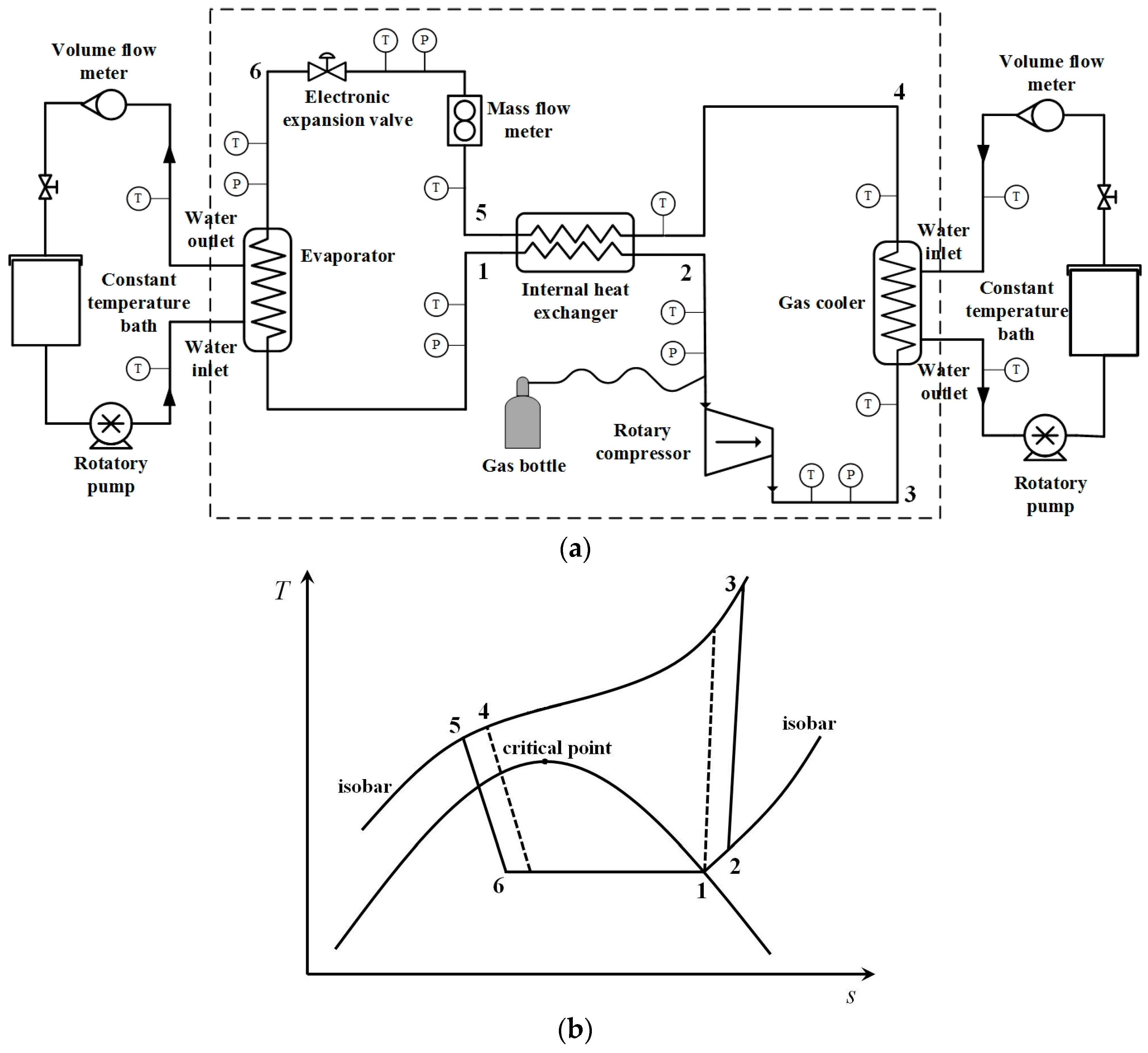
Figure 1 shows the schematic of experimental setup. The present transcritical CO2 system consisted of a rotary compressor, an evaporator, an internal heat exchanger (IHX), a gas cooler, and an electronic expansion valve (EEV). A liquid receiver is included in the rotary compressor. The evaporator and the gas cooler had a counter flow pattern between refrigerant and water. The rated power of the compressor is 2.6 kW. EEV was utilized as an expansion device in the CO2 heat pump system. An adjustable DC power supply was used to control and drive EEV. Pulse values for EEV range from 0 to 480 and it is proportional to EEV input voltage signal. A full stroke (100% opening) of EEV corresponds to 10 V input voltage and a completely close state (0% opening) corresponds to 0 V input voltage. The EEV opening is defined as the ratio of the EEV opening to the full opening. The temperature-entropy diagram of the transcritical CO2 system is shown in Figure 1b. The top point which located at where the saturated liquid and saturated vapor lines meet is called critical point. If temperature and pressure of a refrigerant is higher than that of its critical point, it is supercritical fluid. A Cycle where the refrigerant goes through both subcritical and supercritical states is called transcritical cycle.
Table 1 lists the details about the main components of the system. In order to measure heating capacity simply, water was selected as a heat source and sink for the heat pump system. Two cyclic water systems which contain a thermostatic water tank and a water pump were used to keep the thermal balance in both the gas cooler and the evaporator. A few ball valves and needle valves were used to control the water flow rate supplied to the gas cooler and the evaporator. The water inlet temperature can be achieved by the thermostatic water tank.
The calibrated T-type thermocouples were used for measuring temperature. The welding point of the T-type thermocouples was directly attached to the measured point on copper tubes. Pressure sensors (HSK-BC150D, SAGINOMIYA, Tokyo, Japan) were used for pressure measurement. The pressure sensor is a kind of diffused silicon pressure transmitter which is welded to the experimental copper tube. The sensor can convert pressure difference to displacement by detecting the amount of deflection on a diaphragm position. Then the sensor converts this displacement into a voltage output. The power consumption of the compressor was measured by a power meter (QZ8716C1, Qingzhi Instruments, Qingdao, China) with the accuracy of ±0.1% (voltage 10 V to 500 V, current 0.03 A to 40 A). The water flow rate in the evaporator was measured by a ±0.5% accuracy turbine flow meter (LWGYC-20, Beijing Flowmeter Factory, Beijing, China, measurement range from 0.8 m3·h−1 to 8 m3·h−1) and the water flow rate in the gas cooler was measured by a ±0.5% accuracy turbine flow meter (measurement range from 0.1 m3·h−1 to 0.6 m3·h−1). A mass flow meter (SITRANS F C, Siemens Co., Munich, German) was used to measure the CO2 mass flow rate. A data recorder (MV2000, YOKOGAWA, Tokyo, Japan) was used to obtain the data of temperatures, pressures and flow rates. The entire outer surface of experimental setup was covered with thermal insulation cotton in order to avoid heat loss.

2.2. Test Procedure

Before the test, an important step is to ensure that normal signals can be obtained from pressure sensors, thermocouples and volume flow meters. In addition, make sure that the data recorder was set correctly. The next step is to adjust the water temperature at inlet of gas cooler and evaporator. For this test, tap water was used as heat source and sink. The temperature of tap water was 12 °C when the test was operated in local February. After regulating the water flow rate passing through the gas cooler and the evaporator, the experiment can begin. In order to investigate the efficiency of the heat pump system at actual local conditions, the water entering gas cooler was kept at 12 °C which equals the tap water temperature. In order to provide enough heat for vaporization process of liquid refrigerant and avoid excessive low evaporating temperature happening, the temperature of the water passing through the evaporator is higher than that of the tap water. Therefore, the evaporator inlet water temperature was kept at 16.8 °C. The water flow rate passing through the gas cooler and the evaporator were 0.2 m3·h−1 and 1.6 m3·h−1 respectively. In order to investigate the influence of the refrigerant charge and EEV opening on the performance of system, the water inlet temperature and inlet flow rate were constant during the whole test.
As shown in Figure 1, the working fluid leaves the internal heat exchanger (2) and enters the compressor. The high-pressure vapor leaves the compressor at state (3) and enters the gas cooler. Then the refrigerant transfers the heat to the water of a cyclic water system. In the gas cooler, tap water and refrigerant flows move in opposite directions. At state (4), the cooled CO2 refrigerant enters the internal heat exchanger and heats the working fluid leaving the evaporator. At state (5), the refrigerant enters expansion device, and then expands to the evaporator pressure at state (6). Then the refrigerant enters the evaporator and absorbs heat from the water of another cyclic water system. Countercurrent heat exchange is also used between two flows in the evaporator.
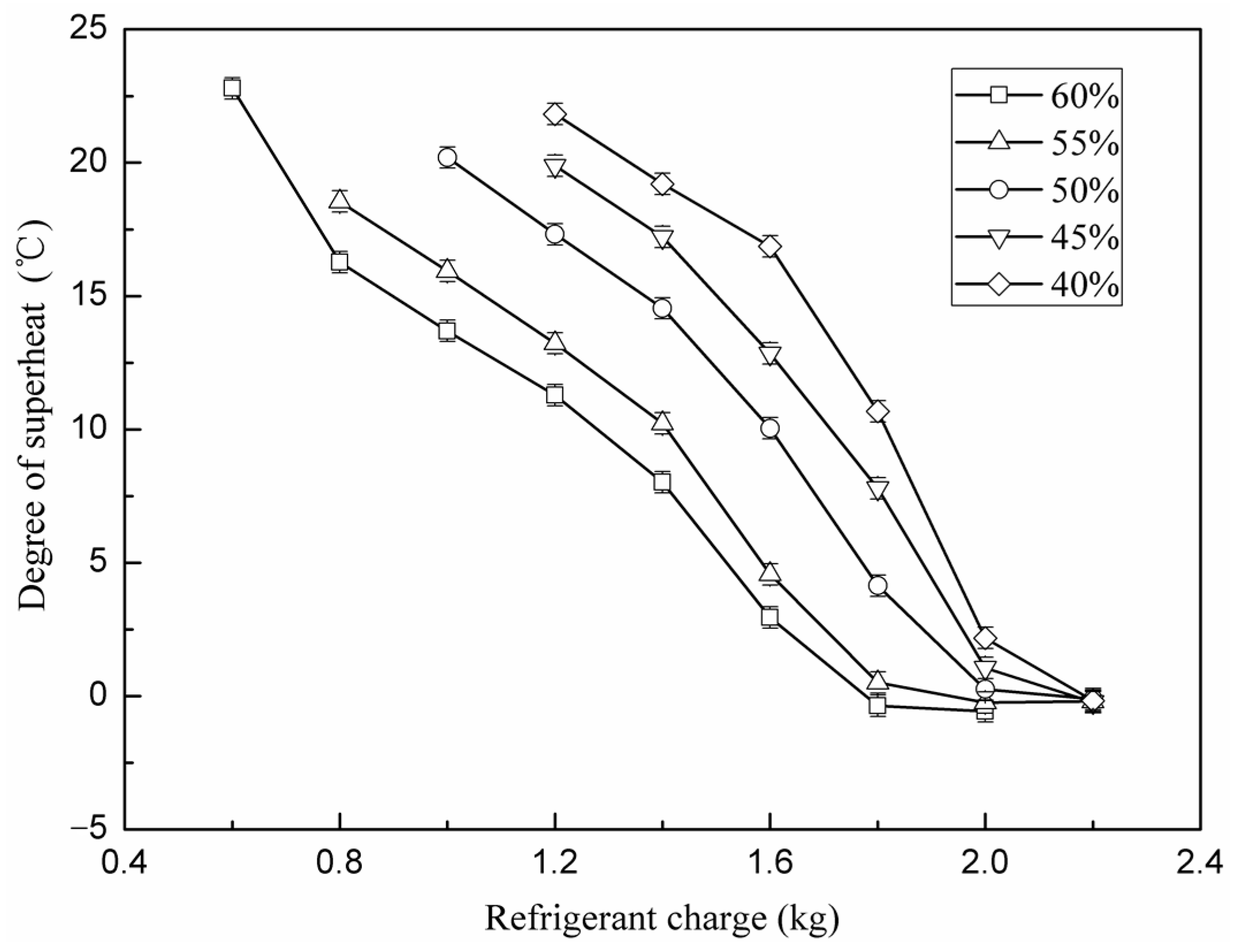
For this transcritical CO2 water-water heat pump system, the refrigerant was added into the system in 200 g increments. With the increase of refrigerant charge amount, the evaporating temperature increased fast at first and then slowly. At this point, the charging process was stopped. Specifically, the experience of the charging refrigerant which summed up during the test was that the evaporating temperature should better be kept between 0 °C and 16 °C. In this study, the EEV opening was manually varied from 40% to 60% of full opening in 5% increment to investigate the influence of EEV openings on the power consumption, key pressures, superheat, mass flow rate, heating capacity and COP.
The heating capacity Q is calculated by using water flow rate and water temperature difference between gas cooler inlet and outlet, as shown in Equation (1):
Q   =   V w ρ w C p , w Δ t
where V w is the volume flow rate of water, ρ w is the density of water, C p , w is the constant-pressure specific heat of water, and Δ t is the temperature rise of the water in the gas cooler.
The COPHP is calculated according to Equation (2):
COP HP   =   V w ρ w C p , w Δ t W
where W is the compressor power consumption. COPHP is the heating COP.
The uncertainties of test results were determined by method of Kline and McClintock [19]. The uncertainty was calculated according to the Equation (3):
ω A   =   [ i = 1 j ( A Z i ω z i ) 2 ] 1 2
where A is a given function of the independent variables, ω A is the total uncertainty in the result, Z i is one of the independent variables which impact the dependent variable A, and ω Z i is the uncertainty associated with an independent variable Z i . The uncertainties of experimental parameters are summarized in Table 2.

3. Results and Discussion

3.1. Effects of Refrigerant Charge and EEV Opening on Heating Capacity

Figure 2 shows the variation of heating capacity for the heat pump system with refrigerant charge amount. With the increase of charge amount at fixed EEV openings, the heating capacity increased rapidly at first, reached its peak and then decreased slowly. The heating capacity increased at first due to the increase of the refrigerant mass flow rate in the gas cooler. When refrigerant amount flowing through the gas cooler increased, more heat was provided. Then the heating capacity dropped due to a decrease of the temperature difference between the refrigerant and the water in the gas cooler. The increase in refrigerant mass flow rate and the decrease in temperature difference lead to a maximum value for heating capacity. The effect of refrigerant charge amount on heating capacity was more sensitive at undercharged conditions than that at overcharged conditions. It was found that the maximum heating capacities and the charge amount which corresponded to the maximum heating capacities were different at different EEV openings. The heating capacity peaked at refrigerant charge amount of 1.8 kg when EEV opening was 40% of full opening. There was a decrease of 15.78% for heating capacity as charge amount reduced 22.22% from optimal charge amount at EEV opening of 40%. However, the reduction of the heating capacity was only by 2.27% as the charge amount increased 22.22% from optimal charge. In order to investigate the reason for changes in heating capacity Q, variations of discharge temperature and refrigerant mass flow rate with refrigerant charge and EEV opening were measured.
It can also be seen from Figure 2 that heating capacity was also affected by EEV openings. As shown in Figure 2, different EEV openings led to different heating capacity at the same charge level. As EEV opening increased from 40% to 60% at the same charge level, the heating capacity decreased. Figure 2 also shows the decrease percentage of heating capacity at 60% EEV opening compared with capacity at 40% EEV opening, as the same charge amount. As EEV opening varied from 40% of full opening to 60%, the heating capacity decreased at most more than 30%.
Figure 3 shows the variations of compressor discharge temperature with refrigerant charge. The discharge temperature decreased gradually with the increase of charge amount due to a decrease of superheat and an increase of mass flow rate. Figure 3 also illustrates that different EEV openings led to different discharge temperature at the same charge level. As EEV opening increased from 40% to 60% at the same charge level, the discharge temperature decreased. This trend was also reported in previous studies by Hou et al. [20]. As shown in Figure 3, the average discharge temperature difference between 60% EEV opening and 40% EEV opening was 28.26 °C when the charge amount was fixed. At fixed EEV opening, the average temperature difference between two adjacent test points was 6.7 °C. The maximum and minimum temperature difference between two adjacent test points was 11.3 °C and 1.84 °C respectively.
For overcharged conditions, the heating capacity dropped with increase of refrigerant charge. The reason for this is that as refrigerant charge increases, the temperature difference between water and refrigerant in the gas cooler decreases. Although the refrigerant mass flow rate increased at overcharged conditions, the effect of temperature difference was greater than that of refrigerant mass flow rate. As refrigerant charge amount decreased, the decrease in refrigerant mass flow rate led to a reduction of the heating capacity at undercharged conditions. Although the temperature difference between the refrigerant and the water increased with the decrease of refrigerant charge amount, the decrease of refrigerant mass flow rate had a greater influence on the variation of heating capacity. The situation was reversed for overcharged conditions. Because of the decrease of the temperature difference between the refrigerant and the water in gas cooler, the heating capacity slightly decreased with the addition of refrigerant charge.
Variations of mass flow rate caused by the increase of refrigerant charge are shown in Figure 4. The mass flow rate increased continuously with the addition of refrigerant charge. At EEV opening of 60%, the average increasing mass flow rate between two adjacent test points reached the maximum value, which was 25 kg·h−1. The minimum average increasing mass flow rate between two adjacent test points was 11.7 kg·h−1 when EEV opening was 45%. Figure 4 also shows that different EEV opening led to different mass flow rate at the same charge level. As EEV opening increased from 40% to 60% at the same charge level, the mass flow rate increased. This is because the large EEV opening lead to a larger port size and smaller resistance. Comparing with the mass flow rate of 1.2 kg and 2.0 kg charge amount at EEV opening of 60%, it dropped by 23.54% and 35.78% when EEV opening was 40% at the same charge level respectively. So it can be concluded that EEV opening can make a significant influence on refrigerant mass flow rate.
Although the mass flow rate of refrigerant increased as EEV openings varied from 40% to 60%, the decrease of discharge temperature played a decisive role on decrease of heating capacity. For overcharged conditions, the heating capacity reduction with an increase of EEV opening was larger than undercharged conditions. When the charge amount was 2 kg, the increasing heating capacity between 40% EEV opening and 60% EEV opening was 2.74 kW which was larger than that of any other charge amounts.
Figure 5 shows the variation of compressor inlet temperature with refrigerant charge amount and EEV opening. The compressor inlet temperature increased at first, reached its peak and then decreased sharply, and finally becoming stable relatively, as the increase of charge amount at fixed EEV openings.

3.2. Effects of Refrigerant Charge and EEV Opening on Superheat

For conventional vapor compression refrigeration system, the degree of subcooling and superheat are important parameters. In a transcritical CO2 system, carbon dioxide at the outlet of the gas cooler may remain in a supercritical state. As temperature of CO2 at gas cooler outlet is higher than CO2 critical temperature, degree of subcooling cannot be calculated. For conventional vapor compression refrigeration system, the superheat is an important parameter which can guard against the situation of wet compression. Furthermore, some kinds of expansion devices such as thermal expansion valve which can adjust refrigerant mass flow rate through a variable expansion are controlled by the superheat at evaporator outlet.
Figure 6 presents variations of superheat with refrigerant charge amount. The superheat reduced gradually as the addition of refrigerant charge due to the rise of the refrigerant flow rate through the evaporator. As shown in Figure 6, the degree of superheat nearly equaled to zero at 2.2 kg charge amount. It may cause wet compression which can result in serious damage to compressors when the degree of superheat is low enough. It can also be seen from Figure 6 that different EEV opening led to different superheat at the same charge level. As the EEV opening increased from 40% to 60% at the same charge level, the superheat decreased due to increase of mass flow rate. At fixed refrigerant charge amount, the difference of superheat between 40% and 60% EEV opening was around 11 °C when the refrigerant charge amount ranged from 1.2 kg to 1.8 kg. However, the growth rate of superheat slowed down with the decrease of EEV opening when the refrigerant charge amount was 2.0 kg. And the degrees of superheats were all same when the refrigerant charge amount was 2.2 kg. Therefore, it can be conclude that smaller EEV opening can lead to higher degree of superheat, which can offer a safer suction condition for the compressor and provide higher evaporator performance. However, it is disadvantageous if the superheat is too high, because the evaporator efficiency decreases with the increase of superheat. To sum up, it is necessary to decrease the EEV opening properly as the addition of refrigerant charge to keep the degree of superheat at an appropriate range.

3.3. Effects of Refrigerant Charge and EEV Opening on Key Pressures

The key pressures, which include pressure of the gas cooler and evaporating pressure, can be affected significantly by the refrigerant charge amount and EEV opening. Figure 7 and Figure 8 show the pressures in the evaporator and gas cooler as functions of refrigerant charge and EEV openings. As refrigerant charge increased, the pressures increased in both the gas cooler and the evaporator due to an accumulation of refrigerant. The pressure in evaporator increased rapidly at first, and then increased gently. With the refrigerant charge ranging from 0.6 kg to 2.2 kg, the pressure in evaporator increased from 2.76 MPa to 4.74 MPa at 60% EEV opening. Meanwhile, the pressure in gas cooler increased approximately linearly from 4 MPa to 8.15 MPa as the refrigerant charge increased from 0.6 kg to 2.2 kg. It can be seen that the increment of the gas cooler pressure was higher than that of evaporating pressure with the increase of charge. The reason for this trend is that the temperature of the water passing through the evaporator limits the increase of evaporating temperature and evaporating pressure. On the other hand, the temperature of the water passing through the gas cooler can increase continuously and get higher temperature rise. So, the interaction between the refrigerant and the water in the gas cooler leads to the continuous increase of the pressure.
Figure 7 and Figure 8 also show that different EEV openings led to different pressures at the same charge level. As EEV opening increased from 40% to 60% of full opening at the same charge level, the pressure in gas cooler decreased due to smaller resistance caused by bigger flow area in EEV. However, it was the opposite situation in evaporator. The reason is that the smaller EEV openings lead to greater pressure drop.
It has been approved by many works in the literature [21,22] that the performance of a CO2 heat pump system is greatly affected by the compressor discharge pressure. This is mainly due to the significant variation of CO2 enthalpy at the inlet of the evaporator with gas cooler pressure, and then further causes greatly variation of cooling capacity and heating capacity. In order to achieve optimal system performance, refrigerant charge amount and EEV opening are most important parameters which need to be controlled intensively.

3.4. Effects of Refrigerant Charge and EEV Opening on Performance

Figure 9 shows the variation of compressor power consumption with refrigerant charge amount. The power consumption increased steadily with the addition of refrigerant charge due to the increase of refrigerant mass flow rate. During the test, the revolving speed and the swept volume of compressor were constant. When refrigerant mass flow increased, the compressor consumed more power in each stroke. As the refrigerant charge increased from 1.2 kg to 2.2 kg, the compressor power consumption increased nearly 350 W at 60%, 55% and 50% EEV openings. It can also be seen from Figure 9 that different EEV opening led to different power consumption at the same charge level. As EEV opening increased from 40% to 60% at the same charge level, the power consumption decreased. Compared with the power consumption at 40% EEV opening, the average decreased compressor consumption was 357.7 W at 60% EEV opening when refrigerant charge amount was fixed. Although refrigerant mass flow rate increased, the smaller resistance caused by increasing EEV opening and lower compression ratio led to decrease of compressor power consumption.
Figure 10 shows the COP of the CO2 heat pump system as functions of refrigerant charge amount and EEV opening. As refrigerant charge amount increased, the COP increased at first, reached its peak and then decreased. The COP had different maximum values at specific CO2 charge amount when EEV opening was different. Based on the experiment, different EEV opening led to different optimal COP. As EEV opening increased, the corresponding optimal COP decreased. In this study, the COP of the heat pump peaked at charge of 1.8 kg when EEV opening was 40% of full opening. Figure 11 shows the decrease percentage of optimal COP as refrigerant charge deviated from corresponding optimal refrigerant charge at different EEV openings. It can be seen that, the reduction of COP caused by improper charge amount was larger at undercharged conditions than that at overcharged conditions just when EEV opening was 50% of full opening. At 50% EEV opening, the COP decreased by 14.95% as the charge amount reduced 22.2% from optimal charge. However, as refrigerant charge amount increased 22.2% from optimal charge, the system heating COP only decreased by 5.5%. Moreover, this tendency was not apparent or even reversed when EEV opening varied as shown in Figure 11.
For undercharged conditions, the COP decreased with the decrease of charge amount due to a rapid decrease of heating capacity. For overcharged conditions, as refrigerant charge increased, the increment of compressor power consumption was higher than the heating capacity result in the reduction of the COP. Figure 10 also shows that different EEV opening led to different COP at the same charge level. As EEV opening ranged from 40% to 60% at the same charge level, the differences between COPs were different. It can be seen that as EEV opening increased from 40% to 60% at the fixed charge amount, the COP decreased when refrigerant charge range from 1.6 kg to 2.0 kg.

4. Conclusions

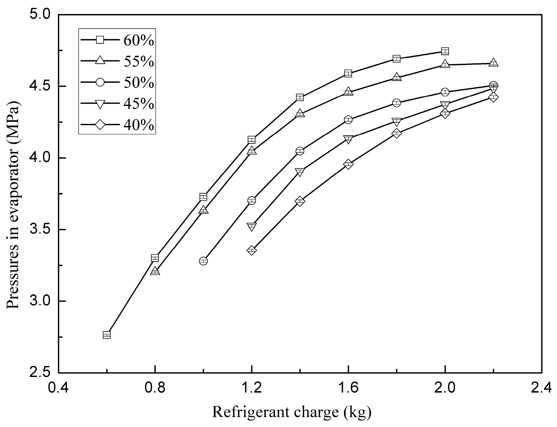
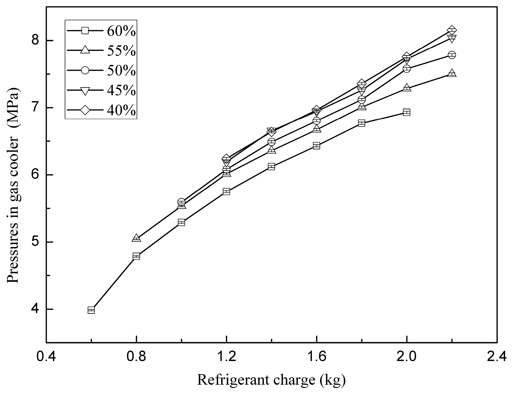
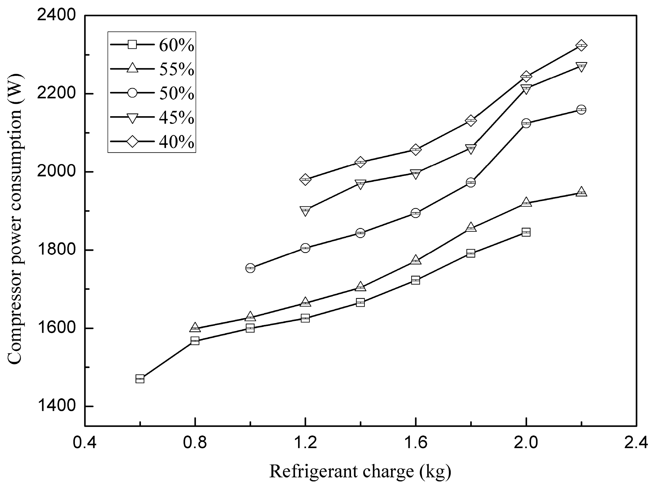
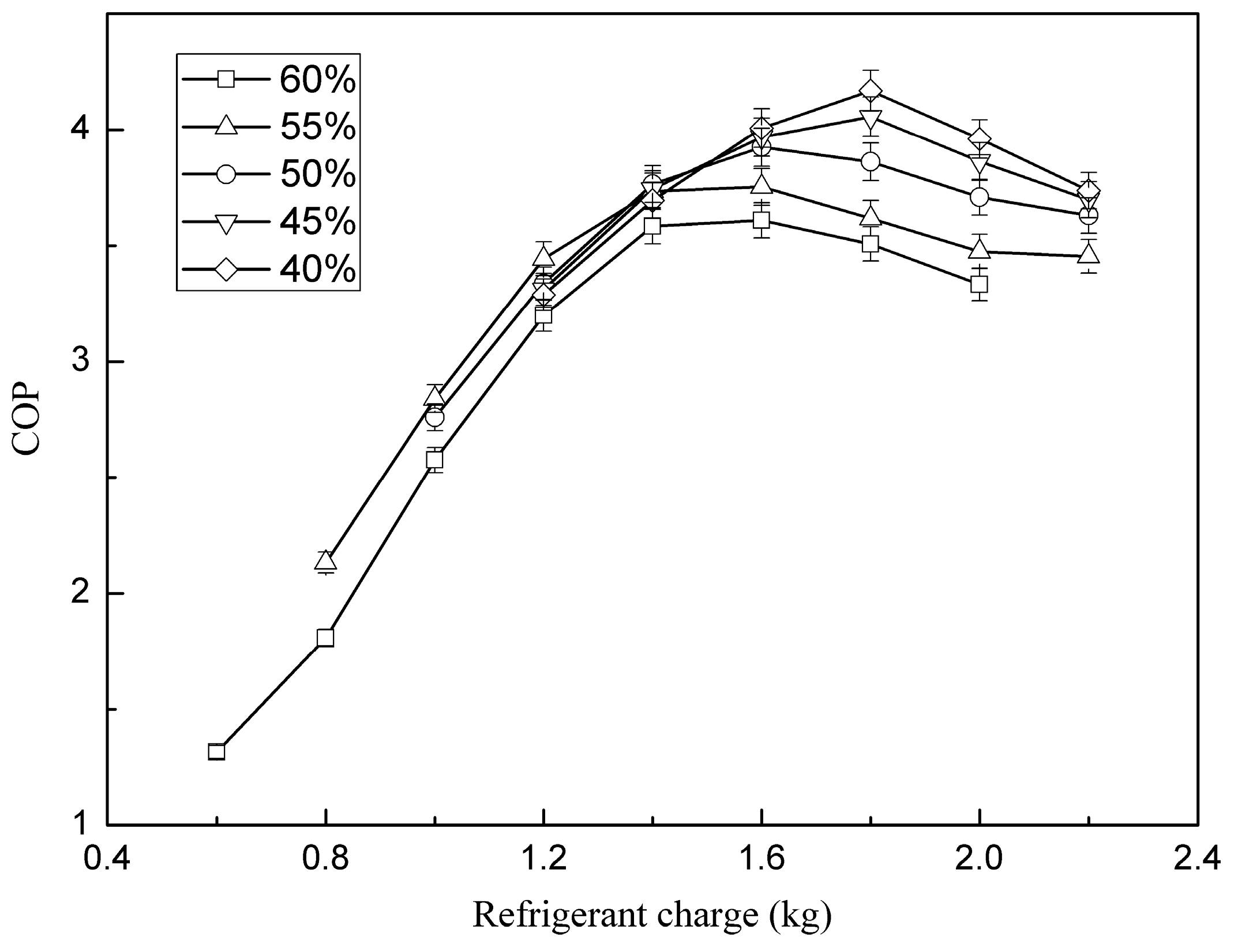
In order to characterize the effects of EEV opening and refrigerant charge amount on the performance of the water source transcritical CO2 heat pump water heater, experiments were carried out by varying the refrigerant charge with different EEV openings. In general, as the refrigerant charge increased, the pressures increased in both the gas cooler and the evaporator. The heating capacity and heating COP increased rapidly at first, reached their peak, and then decreased with the increase of charge amount at fixed EEV opening. As EEV opening increased, the pressures increased in the evaporator and decreased in the gas cooler. The refrigerant mass flow rate increased with the increase of EEV opening. In addition, the superheat decreased with the increase of EEV opening. The other conclusions are as follows:
(1)
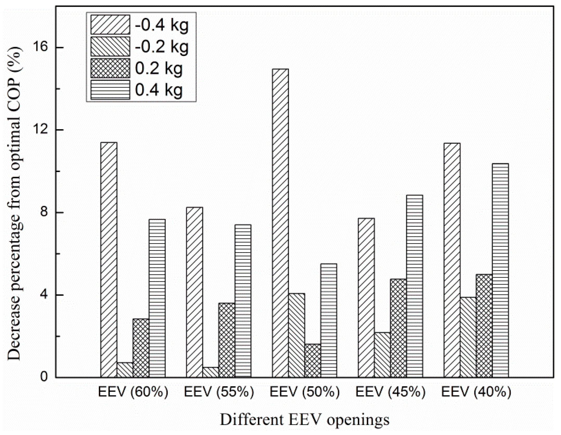
Both the EEV opening and the refrigerant charge amount had a significant effect on the performance of the system. When the other operating parameters of the system unchanged, an optimal COP was found that corresponded to a specific refrigerant charge and a specific EEV opening. Based on the experiment, the COP peaked at charge of 1.8 kg when EEV opening was 40% of full opening. COP has different maximum value at specific CO2 mass charge when EEV opening was different.
(2)
As EEV opening increased, the corresponding optimal COP decreased. In addition, different EEV opening led to different COP at the same charge level.
(3)
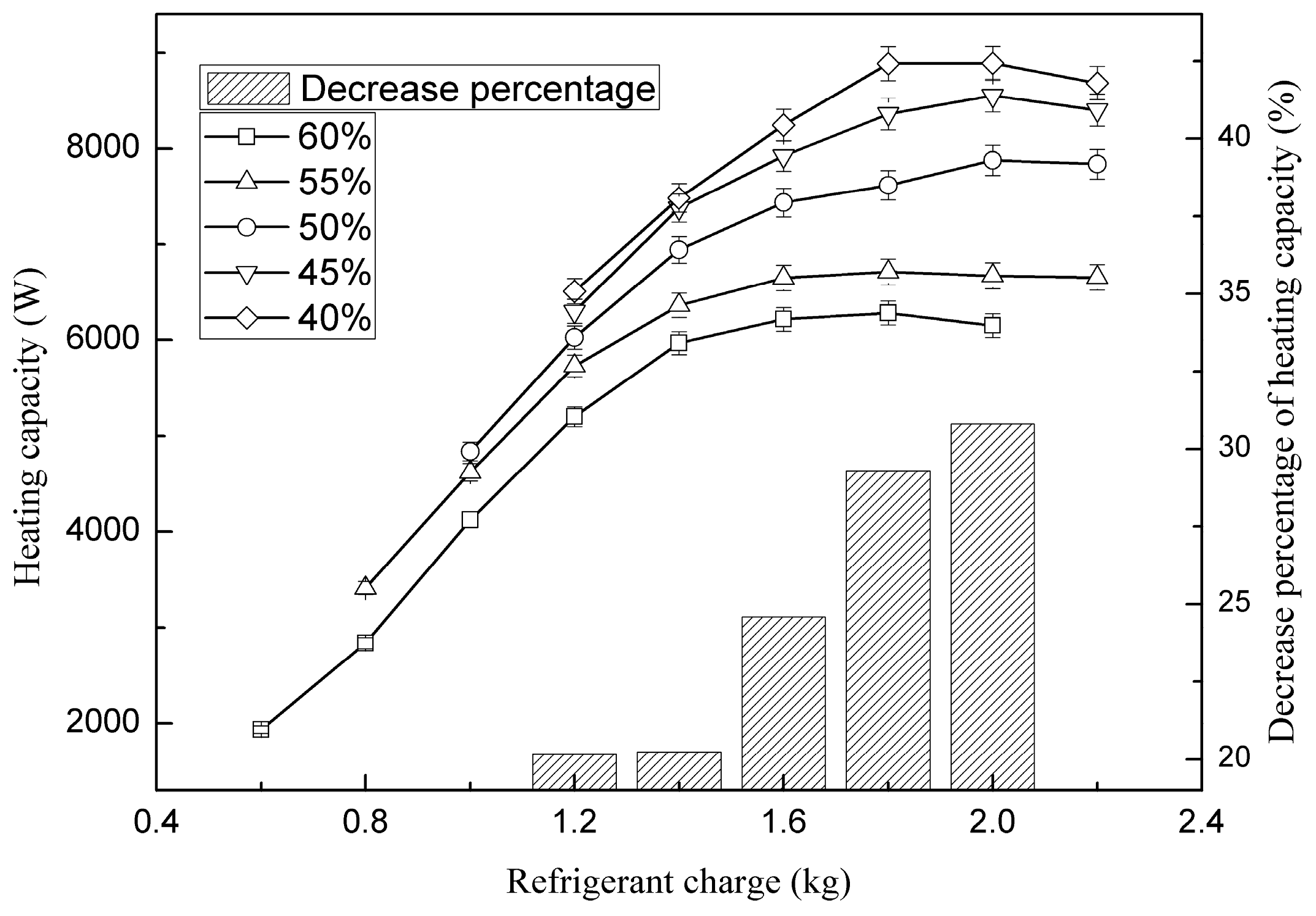
It was found that the heating capacity was also affected by the EEV opening at the same charge amount. As EEV opening varied from 40% of full opening to 60%, the heating capacity decreased, at most, more than 30%.
(4)
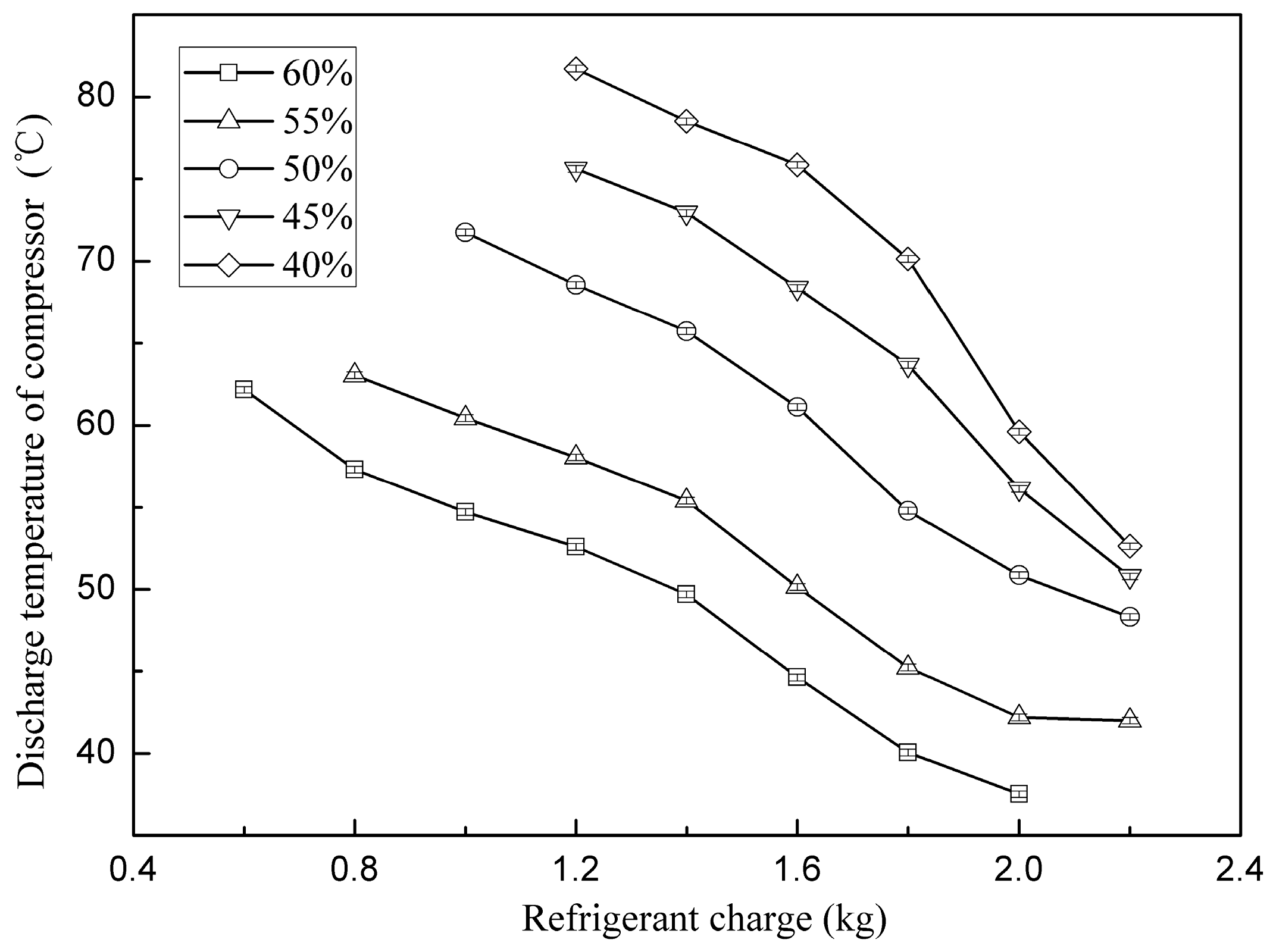
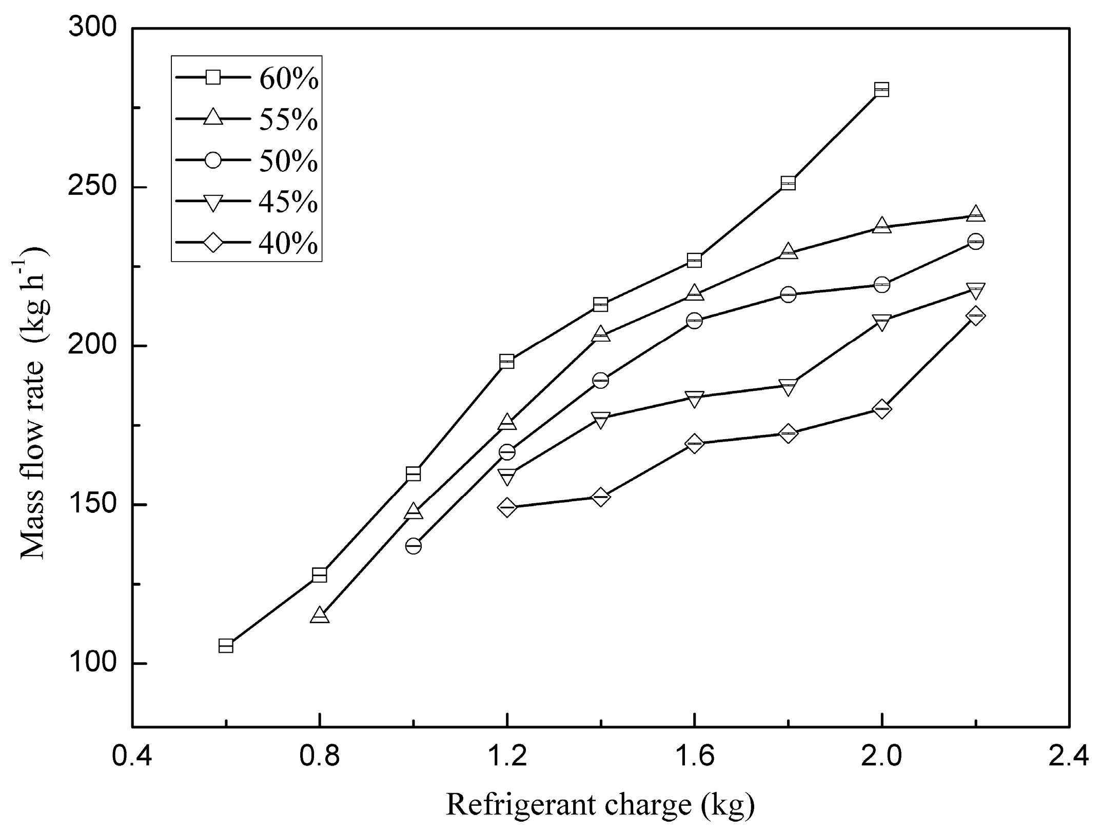
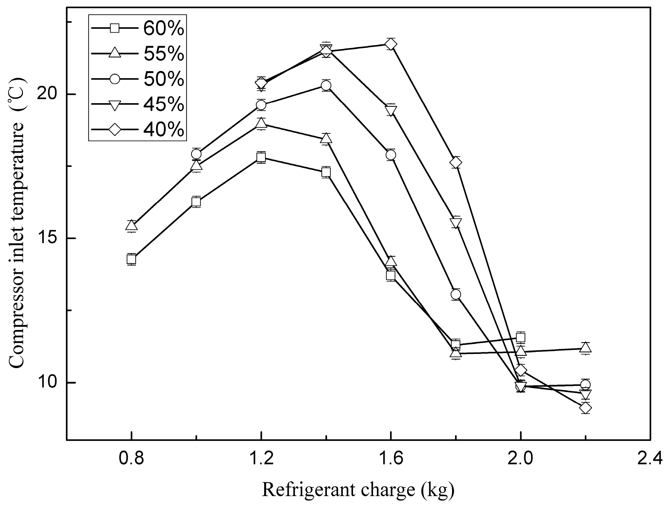
As refrigerant charge amount increased, the mass flow rate and compressor power consumption increased gradually, and the superheat and compressor discharge temperature decreased. The main reason for variation of superheat is the increase of refrigerant mass flow rate passing through evaporator. The reason for variation of compressor discharge temperature is the decrease of superheat and the increase of refrigerant mass flow rate.
(5)
The reduction of COP caused by improper charge amount was larger at undercharged conditions than that at overcharged conditions just when EEV opening was 50% of full opening. Moreover, this tendency was not apparent or even reversed when EEV opening varied.
Therefore, both refrigerant charge amount and EEV opening are important factors influencing the performance of CO2 heat pump system. It is essential to have the optimum amount of refrigerant charge and more precisely, control of EEV opening to ensure highest performance operation of the CO2 heat pump system. Although the optimal values obtained from this study may vary due to the differences in system configuration and system size, the variable relationship between system parameters and EEV opening as well as refrigerant charge can be generalized to other heat pump systems which have the same system components as this study. Control modules which can real-time control the COP of the heat pump system by adjusting EEV opening and refrigerant charge would be the future development direction.

Acknowledgments

This project was supported by the Natural Science Foundation of Jiangsu Province (BK20140408, BK20160388) and the Prospective Joint Research Project (BK2014071) of Jiangsu Province, China.

Author Contributions

Ze Zhang designed the experiments; Xiaojun Dong built up the experimental apparatus; Zheng Ren and Tianwei Lai carried out the experimental study; Yu Hou analyzed the experimental data. All authors contributed equally in the writing and revision of this paper.

Conflicts of Interest

The authors declare no conflict of interest.

References

  1. Kim, M.-H.; Pettersen, J.; Bullard, C.W. Fundamental process and system design issues in CO2 vapor compression systems. Prog. Energy Combust. Sci. 2004, 30, 119–174. [Google Scholar] [CrossRef]
  2. Yılmaz, F.; Özdemir, A.; Şencan Şahin, A.; Selbaş, R. Prediction of Thermodynamic and Thermophysical Properties of Carbon Dioxide. J. Thermophys. Heat Transf. 2014, 28, 491–498. [Google Scholar] [CrossRef]
  3. Lorentzen, G.; Pettersen, J. A new efficient and environmentally benign system for car air-conditioning. Int. J. Refrig. 1993, 16, 4–12. [Google Scholar] [CrossRef]
  4. Antonijević, D.L. Carbon dioxide as the replacement for synthetic refrigerants in mobile air conditioning. Therm. Sci. 2008, 12, 55–64. [Google Scholar] [CrossRef]
  5. Saikawa, M.; Koyama, S. Thermodynamic analysis of vapor compression heat pump cycle for tap water heating and development of CO2 heat pump water heater for residential use. Appl. Therm. Eng. 2016, 106, 1236–1243. [Google Scholar] [CrossRef]
  6. Zhang, J.F.; Qin, Y.; Wang, C.C. Review on CO2 heat pump water heater for residential use in Japan. Renew. Sustain. Energy Rev. 2015, 50, 1383–1391. [Google Scholar] [CrossRef]
  7. Minetto, S.; Brignoli, R.; Banasiak, K.; Hafner, A.; Zilio, C. Performance assessment of an off-the-shelf R744 heat pump equipped with an ejector. Appl. Therm. Eng. 2013, 59, 568–575. [Google Scholar] [CrossRef]
  8. Mosaffa, A.H.; Farshi, L.G.; Ferreira, C.A.I.; Rosen, M.A. Exergoeconomic and environmental analyses of CO2/NH3 cascade refrigeration systems equipped with different types of flash tank intercoolers. Energy Convers. Manag. 2016, 117, 442–453. [Google Scholar] [CrossRef]
  9. Zhang, D.; Wu, Q.B.; Li, J.P.; Kong, X.Q. Effects of refrigerant charge and structural parameters on the performance of a direct-expansion solar-assisted heat pump system. Appl. Therm. Eng. 2014, 73, 522–528. [Google Scholar] [CrossRef]
  10. Vjacheslav, N.; Rozhentsev, A.; Wang, C.C. Rationally based model for evaluating the optimal refrigerant mass charge in refrigerating machines. Energy Convers. Manag. 2001, 42, 2083–2095. [Google Scholar] [CrossRef]
  11. Ratts, E.B.; Brown, J.S. An experimental analysis of the effect of refrigerant charge level on an automotive refrigeration system. Int. J. Therm. Sci. 2000, 39, 592–604. [Google Scholar] [CrossRef]
  12. Choi, J.M.; Kim, Y.C. The effects of improper refrigerant charge on the performance of a heat pump with an electronic expansion valve and capillary tube. Energy 2002, 27, 391–404. [Google Scholar] [CrossRef]
  13. Choi, J.; Kim, Y. Influence of the expansion device on the performance of a heat pump using R407C under a range of charging conditions. Int. J. Refrig. 2004, 27, 378–384. [Google Scholar] [CrossRef]
  14. Corberán, J.M.; Martínez, I.O.; Gonzálvez, J. Charge optimisation study of a reversible water-to-water propane heat pump. Int. J. Refrig. 2008, 31, 716–726. [Google Scholar] [CrossRef]
  15. Corberán, J.M.; Martínez-Galván, I.; Martínez-Ballester, S.; Gonzálvez-Maciá, J.; Royo-Pastor, R. Influence of the source and sink temperatures on the optimal refrigerant charge of a water-to-water heat pump. Int. J. Refrig. 2011, 34, 881–892. [Google Scholar] [CrossRef]
  16. Kim, W.; Braun, J.E. Evaluation of the impacts of refrigerant charge on air conditioner and heat pump performance. Int. J. Refrig. 2012, 35, 1805–1814. [Google Scholar] [CrossRef]
  17. Kim, J.H.; Cho, J.M.; Lee, I.H.; Lee, J.S.; Kim, M.S. Circulation concentration of CO2/propane mixtures and the effect of their charge on the cooling performance in an air-conditioning system. Int. J. Refrig. 2007, 30, 43–49. [Google Scholar] [CrossRef]
  18. Cho, H.; Ryu, C.; Kim, Y.; Kim, H.Y. Effects of refrigerant charge amount on the performance of a transcritical CO2 heat pump. Int. J. Refrig. 2005, 28, 1266–1273. [Google Scholar] [CrossRef]
  19. Kline, S.J.; McClintock, F.A. Describing uncertainties in single-sample experiments. Mech. Eng. 1953, 75, 3–8. [Google Scholar]
  20. Hou, Y.; Ma, J.; Liu, C.; Cao, J.; Liu, X. Experimental investigation on the influence of EEV opening on the performance of transcritical CO2 refrigeration system. Appl. Therm. Eng. 2014, 65, 51–56. [Google Scholar] [CrossRef]
  21. Chen, Y.; Gu, J. The optimum high pressure for CO2 transcritical refrigeration systems with internal heat exchangers. Int. J. Refrig. 2005, 28, 1238–1249. [Google Scholar] [CrossRef]
  22. Kauf, F. Determination of the optimum high pressure for transcritical CO2-refrigeration cycles. Int. J. Therm. Sci. 1999, 38, 325–330. [Google Scholar] [CrossRef]
Figure 1. Schematic diagram of the experimental setup: (a) Schematic diagram, (b) T-s diagram.
Energies 10 01521 g001
Figure 2. Variations of heating capacity with refrigerant charge and EEV opening.
Energies 10 01521 g002
Figure 3. Variations of discharge temperature with refrigerant charge and EEV opening.
Energies 10 01521 g003
Figure 4. Variations of mass flow rate with refrigerant charge and EEV opening.
Energies 10 01521 g004
Figure 5. Variations of compressor inlet temperature with refrigerant charge and EEV opening.
Energies 10 01521 g005
Figure 6. Variations of degree of superheat with refrigerant charge and EEV opening.
Energies 10 01521 g006
Figure 7. Variations of the pressures in evaporator with refrigerant charge and EEV opening.
Energies 10 01521 g007
Figure 8. Variations of the pressures in gas cooler with refrigerant charge and EEV opening.
Energies 10 01521 g008
Figure 9. Variations of compressor power consumption with refrigerant charge and EEV opening.
Energies 10 01521 g009
Figure 10. Variations of COP with refrigerant charge and EEV opening.
Energies 10 01521 g010
Figure 11. Decrease percentage from optimal COP as refrigerant charge deviated from corresponding optimal charge.
Energies 10 01521 g011
Table 1. Main components of the system.
NameTypeMain Characteristic
CompressorHermetic rolling rotor compressorSwept volume: 8.3 cm3
Rated capacity: 2.6 kW
Frequency: 50 Hz
Gas coolerTube in tube heat exchangerHeat transfer area: 1.5 m2
EvaporatorTube in tube heat exchangerHeat transfer area: 1.5 m2
Expansion valveElectronic expansion valvePort size: 2.0 mm
Step (pulse): 0–480
Input voltage: 0–10 V
Internal heat exchangerTube in tube heat exchangerHeat transfer area: 0.08 m2
Table 2. Uncertainties of experimental parameters.
ParametersUncertaintyFull Scale
Pressure transducer±0.25%16 Mpa
Temperature±0.2 °C−10–150 °C
Power meter±0.1%20 kW
Mass flow meter±0.1%5600 kg·h−1
Turbine flow meter±0.5%0.1–0.6 m3·h−1 and 0.8–8 m3·h−1
Electronic balance weight±1 g100 kg
Heating capacity±2%-
COPHP±2.1%-

