1. Introduction
As one of many energy storage solutions, lithium-ion batteries (LIBs) are attracting more and more attention from researchers and users due to their high energy density, high power density, long lifespan and environmental friendliness [
1,
2]. The LIBs have been used in energy-storage applications in solar panel systems from those that use a few kilowatt-hours in residential systems to multi-megawatt batteries in grid power systems. There are also broad applications in some high-power applications such as electric vehicles using large numbers of serial or parallel battery cells [
3,
4,
5,
6,
7,
8]. However, despite being a promising candidate for energy storage solutions, these batteries are facing some challenges, such as ensuring safe operation of the battery-power system that depends on the accurate state-of-charge (SOC) estimation [
9,
10,
11]. The safety of the LIB power system is crucial, especially when the battery-power system is grouped by a considerable number of battery cells in serial or parallel topology, or in a battery stack, to give a higher power density. The LIBs can deteriorate if they are to operate beyond the battery specifications [
9,
10].
The estimations of SOC in the battery management system (BMS) can improve the system performance and reliability. However, battery discharge and charge involve complex chemical and physical processes while in operation. It is therefore not easy to estimate the SOC accurately under various operational conditions [
12,
13,
14]. There are several kinds of LIBs in the market, such as those containing LiFeO
4, lithium polymers and LiCoO
2. With the different dynamic behavior of the batteries and their topology, specific SOC algorithms are sometimes required. There have been many development and research works in recent years to improve SOC estimation accuracy [
13,
15,
16,
17,
18]. Firstly, the standard measurement-based estimation approaches, such as the coulomb-counting or ampere-hour (Ah) methods, as well as the open-circuit voltage (OCV) and impedance measurement methods, give a more intuitive and reliable estimation [
19,
20]. However, this approach is prone to errors: errors related to initial SOC determination and the accumulative errors from sensors during the measurement of current and time. Secondly, the machine learning-based estimation methods (also called data-driven approaches), such as the artificial neural network–fuzzy logic (FL) [
16] and support vector machine [
17] methods. However, machine learning-based methods require a high computational effort due to large training datasets for training the model, although they consider the nonlinearities of the battery model. In addition, most machine learning-based SOC estimation models were established offline. They are not suitable for a practical and low-cost embedded battery-power system application. Lastly, the state-space model-based estimation methods (such as using the extended Kalman filter (EKF)) reduce the convergent time but increase the computational load of the BMS [
21,
22]. The aforementioned literature has its own disadvantages and advantages. However, what is unusual is that most SOC implementation is only meant for a single battery cell. It is not useful for researchers who would like to implement it on multi-cell batteries for actual applications.
Due to the characteristics of LIBs, the faults of the battery-power system may lead to serious safety issues, such as catching fire and explosion. For instance, a lithium–cobalt oxide battery backup power system caught fire in a Boeing 787 of Japan Airlines in 2013 [
23]. Hence, the capabilities of fault diagnosis and protection are important and necessary in a battery-power system. Fault-diagnosis technology is an interdisciplinary field that combines control theory, computer network, database, artificial intelligence and other technologies. In the past few years, there were many researchers focused on battery-power systems. Bohlen et al. [
24] investigated the internal-resistance fault diagnosis of batteries by a model-based identification method. D.P. Abraham et al. [
25] proved that the changes of battery electrodes are the cause of the sudden increase in the battery internal resistance and the power degradation mechanism in the power battery pack. X.J. Liu [
26] tried to diagnose the battery faults by using the fuzzy-logic method. Although the research involved different methods or models that produced good results, most of the authors were focusing on overall theoretical aspects of fault diagnosis using nonlinear model-based or intelligent approaches, such as fuzzy-logic and neural network methods, to determine the battery faults. However, these required a higher computational time and further resources to perform the fault diagnosis. Therefore, in this study, one of the research objectives is to use a computational, inexpensive and intuitive approach to detect and diagnose the faults in the battery and provide corresponding remedy actions for the faults. In addition, the self-recovery scheme is also proposed. Firstly, four types of critical faults [
9,
10,
26,
27,
28,
29,
30,
31,
32], being the over-charged fault, over-discharged fault, over-current fault and external short-circuit fault, are considered. Secondly, different fault diagnosis algorithms are studied, and the corresponding solutions are proposed. Lastly, the proposed fault diagnosis and self-recovery schemes are applied to the 12-cell battery pack prototype and validated experimentally.
In summary, a structure of a smart multi-cell battery-power system is proposed to improve the safety and its operational intelligence. Hence, the smart battery-power system has the following features: (1) compatibility and flexibility with different kinds of LIBs and battery pack configurations; (2) capability for SOC self-initialization and self-adjustment; (3) capability for fault diagnosis and self-recovery; and (4) ability to provide a human–machine interface for status report and system configuration, locally or in the cloud. A few designed modules, such as battery data acquisition, battery pack SOC estimation, fault diagnosis, data communication, user-interface module for data display and system configuration, and dual-path switching for charging and discharging, are proposed. In the proposed smart battery-power system, the SOC self-initialization scheme coupled with fault diagnosis and the self-recovery algorithm were investigated and implemented in a 12-cell series (12S) battery-pack prototype. The experimental results show that the system can diagnose the faults and carry out the corresponding protection and recovery actions. In addition, the proposed battery pack has been shown to estimate the SOC successfully under the actual load profile from an electric vehicle.
The rest of this paper is organized as follows:
Section 2 presents the system design by different modules. It is followed by
Section 3 that deals with the implementation and demonstration of the proposed system in a 12S battery-pack prototype. Finally,
Section 4 concludes the work.
2. Proposed Battery-Power System Design
This section encompasses the design and development of a smart LIB battery-power system for SOC estimation, intelligent fault diagnosis and protection for a typical energy-storage module consisting of a 36 V battery pack module with 12-cell series LIBs (ANR26650M1-B) that can be scaled up to 120 cells in series.
2.1. System Structure Design
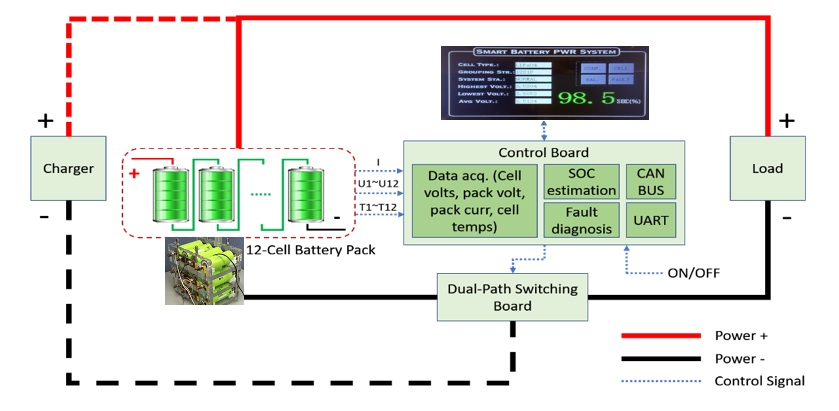
The proposed smart LIB system has three main parts: controller hardware that includes a microcontroller (MCU) with necessary interfaces and peripherals, embedded software for SOC and fault diagnosis implementation, and a 3.5-inch touchscreen thin-film-transistor liquid-crystal display (TFT LCD) as a user interface for data display and system configuration. The overall system structure is shown in
Figure 1.
The power system periodically measures the voltage value of each cell and the battery pack’s current and voltage using suitable analog-to-digital converters (ADCs) and sensors. The controller can perform the SOC estimation and fault-diagnosis algorithms in real-time using measured voltages, current values, temperature values ands the parameters obtained from the touch screen LCD (such as the battery-cell material, battery-cell capacity, battery-cell maximum discharged current and battery topology). The SOC estimation and fault diagnosis results will be displayed on the LCD and sent to the host PC for further processing via a universal asynchronous receiver–transmitter (UART). If the battery pack is grouped into more than 12 cells in series, the controller area network (CAN bus) will communicate with other peer systems or the master system. However, the heat generated from the charging or discharging switches affects the performance of the power system during the high-current application. A dual-path switching board is designed specially to separate the charging and discharging paths to decrease the heat generated from the switches. In addition, a phase-change material (PCM) capable of storing the heat generated will be used. The heat generated is estimated to be reduced by 50% on the discharging path.
2.2. Data Acquisition and SOC Estimation with Self-Initialization Capability
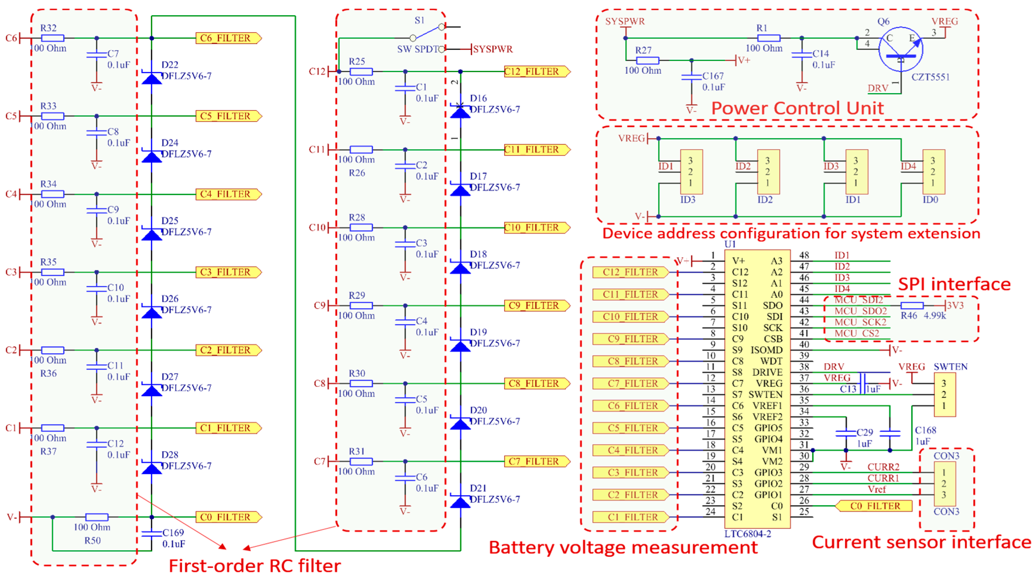
During the system running process, many parameters, such as the cell voltage, temperature, pack voltage and current, must be collected in real-time. The status of the battery pack, such as SOC, is required for continuous fault diagnosis. Therefore, the accuracy of the SOC estimation is critical to the system performance. A high-accuracy data-acquisition method using the LTC6804 is selected as an analog-to-digital converter to monitor the battery pack. It can measure the battery cells with a total measurement error of less than 1.2 mV. The measurement range from 0 to 5 V makes the LTC6804 suitable for the LIB application, as it does not consume much power. The speed of the data acquisition is fast enough with the 12-cell voltages that are sampled at 290 µs. However, lower data-acquisition rates can be used for higher noise reduction. The configuration of this hardware module can be seen in
Figure 2. The precision of the LTC6804 was around 0.3%. However, the overall system accuracy can be affected by the print circuit board (PCB) design. Nevertheless, the precision target of 6% can be obtained by continuous calibration for the case of a lower-current application.
The releasable capacity (C
releasable) of an operating battery is the released capacity when it is completely discharged. The SOC is defined as the percentage of the releasable capacity relative to the battery-rated capacity (C
rated), given as follows:
A fully charged battery has the maximal releasable capacity (C
max), which can be different from the rated capacity. In general, C
max declines as time increases. Hence, the C
max can be used for evaluating the state-of-health (SOH) of a battery:
When a battery is discharging, the depth of discharge (DOD) can be defined as the percentage of the capacity that has been discharged (C
released) relative to C
rated:
With a measured battery current (
It), the difference of the DOD in an operating period (
T) can be computed by:
By considering the SOH, the SOC is estimated as:
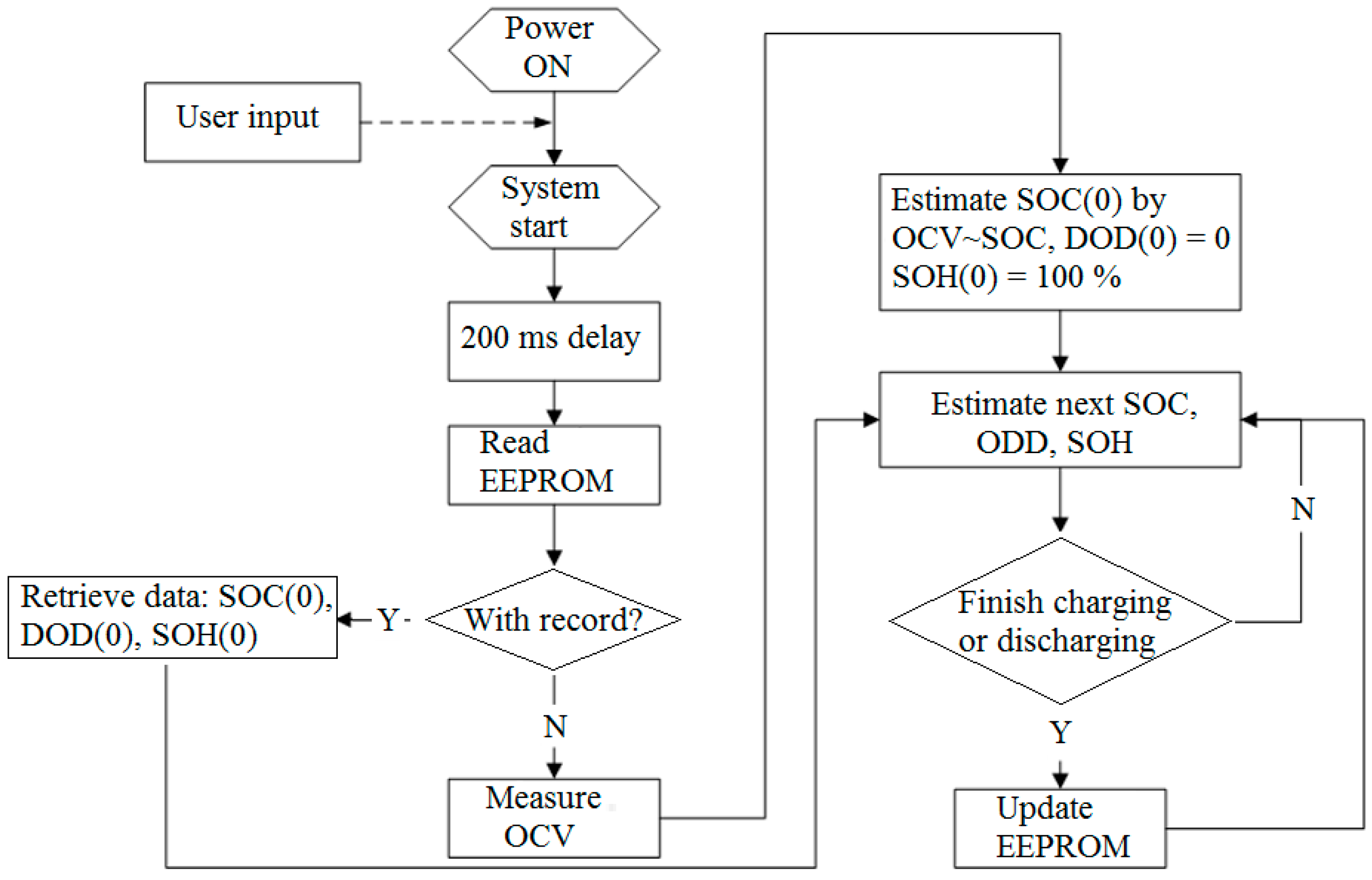
In order to improve the convergence performance of SOC estimation, an accurate method to determine the initial status of the batteries will be used. However, unlike the lab environment, it is hard to know the exact initial SOC and DOD of the battery. Therefore, a self-initialization method for the battery system is proposed and implemented to provide prior configuration during the initialization stage.
At the charging stage, the variations of the battery voltage and battery current when the battery is charged by the constant current–constant voltage (CC–CV) mode are usually specified by the manufacturer. With the constant charging current, the battery voltage increases gradually and reaches the threshold. Once the battery has been charged by the constant voltage mode, the charging current reduces rapidly before it more gradually decreases. Eventually, the current will reach almost zero when it is fully charged. This charging curve can be converted into the relationship between the charging voltage and the SOC, during the constant current stage. By using the relationship between the charging current and the SOC during the constant-voltage stage, the initial SOC value can be obtained.
At the discharging stage, the typical voltage curves at different discharging currents are given by the manufacturer. A higher current will cause a faster decline in the terminal voltage, and lead to a shorter operation time. The relationship between the SOC and the discharging voltage at different currents can be obtained. At the open-circuit stage, the relationship between open-circuit voltage (OCV) and SOC is needed. The battery is discharged by different currents before disconnecting from the load. The OCV can be used to estimate SOC if a long period of relaxation is given for the transient to settle to its steady state.
Figure 3 is the flowchart to indicate the self-initialization procedures for SOC estimation when the system restarts after a long period of relaxation.
2.3. Smart Fault-Diagnosis Strategies
As the LIBs provide a high-energy-density power, the system must be able to detect the abnormality in real-time to ensure the safety of the users and efficient power supply under unexpected conditions, such as an external short circuit. The safety of Li-ion batteries depends on the attributes of system design, such as electronics, estimation algorithms, and thermal and mechanical characteristics, regardless of electrochemistry. They should be equipped with the capability to diagnose the faults, and perform a corresponding corrective action. In addition, they need to carry out a self-recovery action after the fault conditions are eliminated.
2.3.1. External Short-Circuit Fault Diagnosis of a Battery Pack
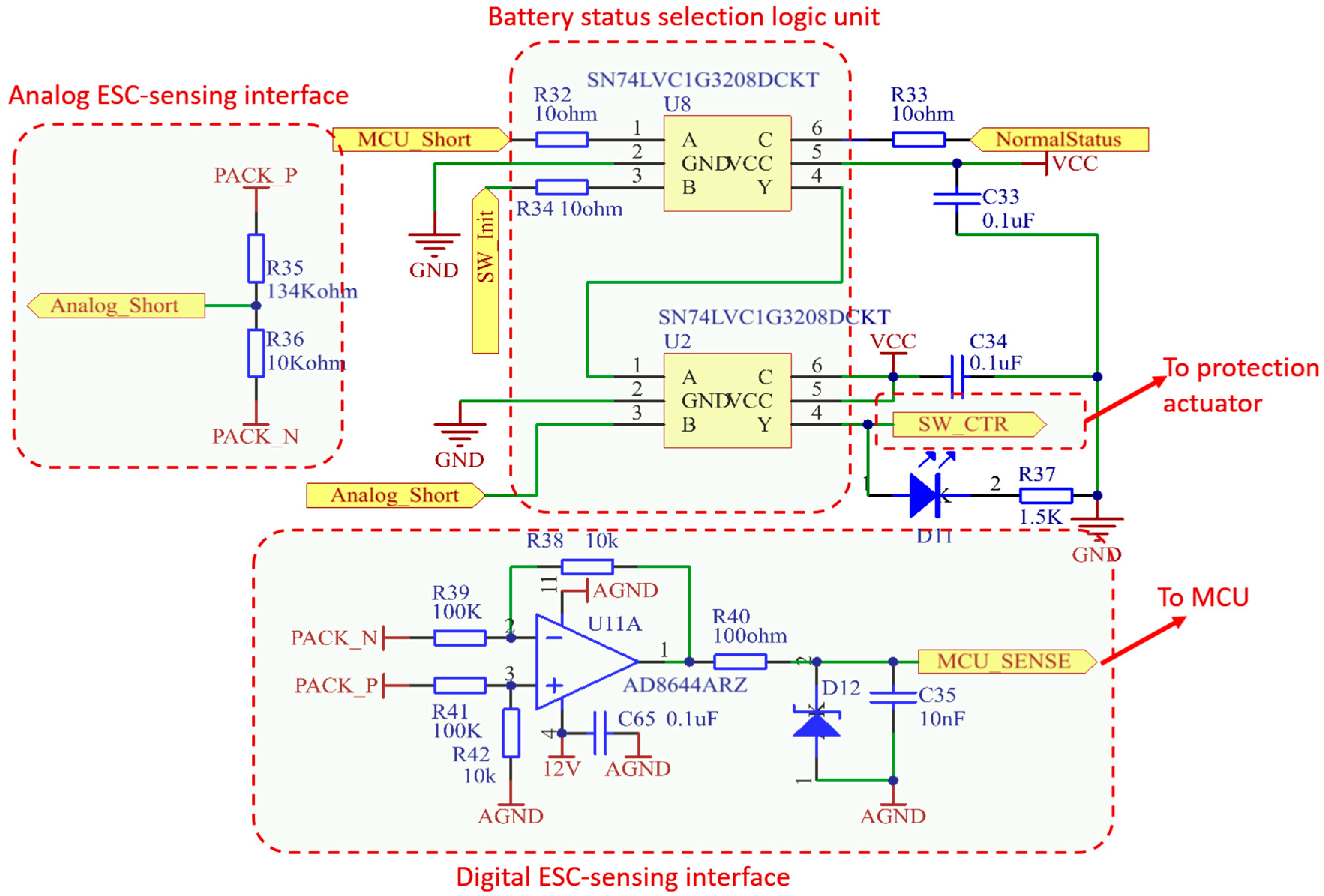
The external short-circuit to the power system is a common fault that happens during installation or uninstallation processes of the battery-power system. Dual diagnosis and protection schemes are designed and implemented into the system to ensure that the fault can be isolated reliably and timely without affecting other components. The hardware design for the external short-circuit can be seen in
Figure 4. The dual diagnosis and protection schemes consist of the following analog and digital diagnosis and protection systems:
- (a)
Analog diagnosis and protection scheme: this scheme detects the fault by a specially designed analog circuit. Once the fault is detected, the circuit will inform the actuator (i.e., the switching board within the control board in
Figure 1) to carry out the protection action immediately. This avoids polling time of the software algorithm. The output signal will reset, and the system will recover once the fault condition has been eliminated.
- (b)
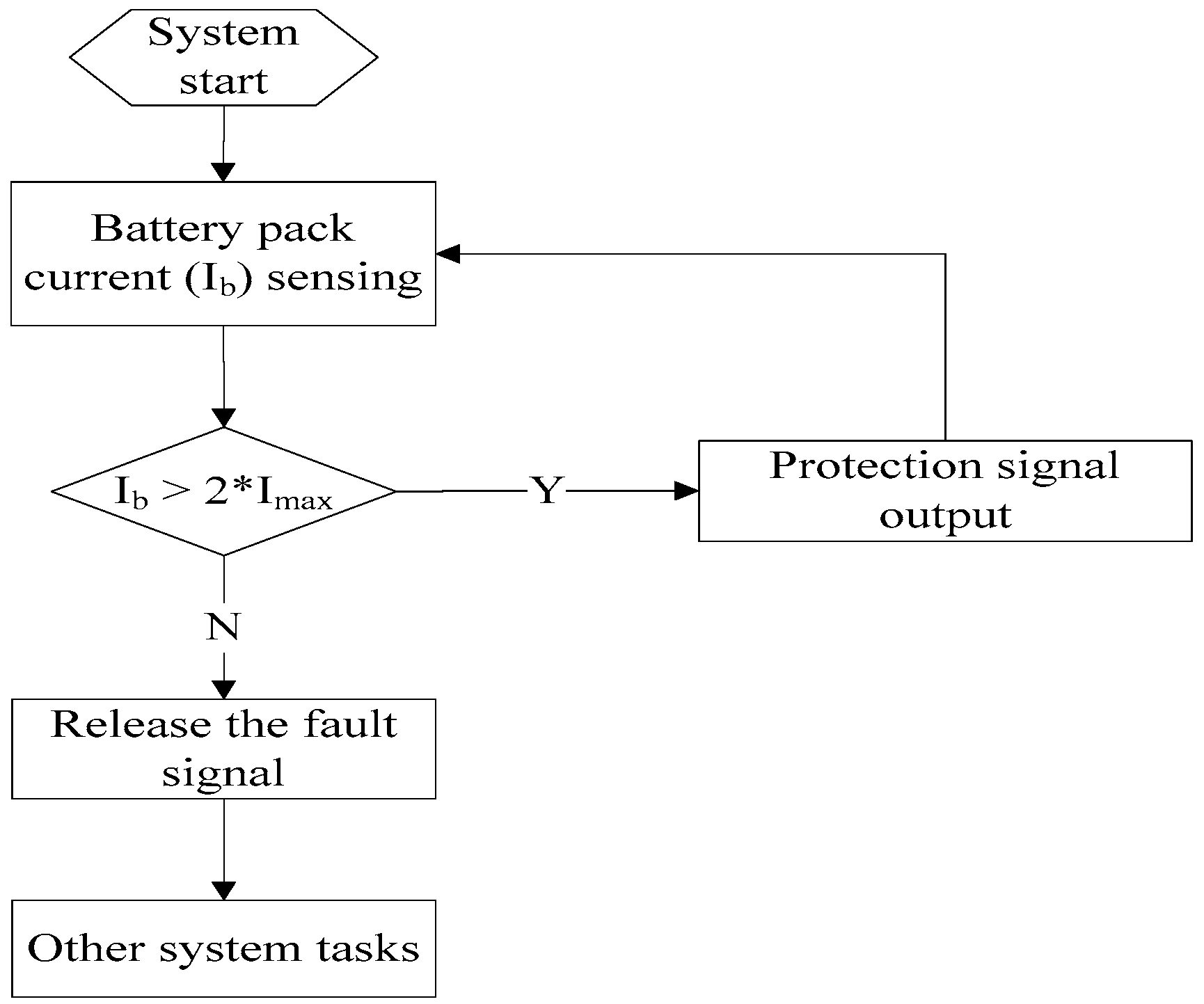
Digital diagnosis and protection scheme: this method periodically detects the faults by software polling. The strategy is as follows: if the discharge current is more than twice the power-pack maximum current,
Imax, the current will vary across the batteries to enable the external short-circuit fault to be detected. The MCU will give a signal to perform the protection action. This ensures the fault is isolated effectively when the analog diagnosis and protection scheme does not work properly. The output signal will reset to its normal state once the fault condition has been eliminated. A flowchart of the digital diagnosis and protection scheme of the external fault diagnosis is depicted in
Figure 5.
2.3.2. Fault Diagnosis of Battery Cells
The over-charged, over-discharged, over-current and over-temperature conditions are the four different fault conditions of the battery cells. They can cause permanent damage to the battery cells. As these fault conditions are related to the parameters of the battery, they are included in the fault diagnosis. Battery charge and discharge involve complex chemical and physical processes. However, the over-charged, over-discharged and over-current states can also lead to fire due to the explosion of the cells. To circumvent these problems, the battery-charging or discharging voltage needs to be monitored continuously in real-time. If the upper or lower cut-off voltage or the current reaches the maximum value, the system controller will use the over-charged/over-discharged/over-current protection to stop the charging or discharging of the battery cells.
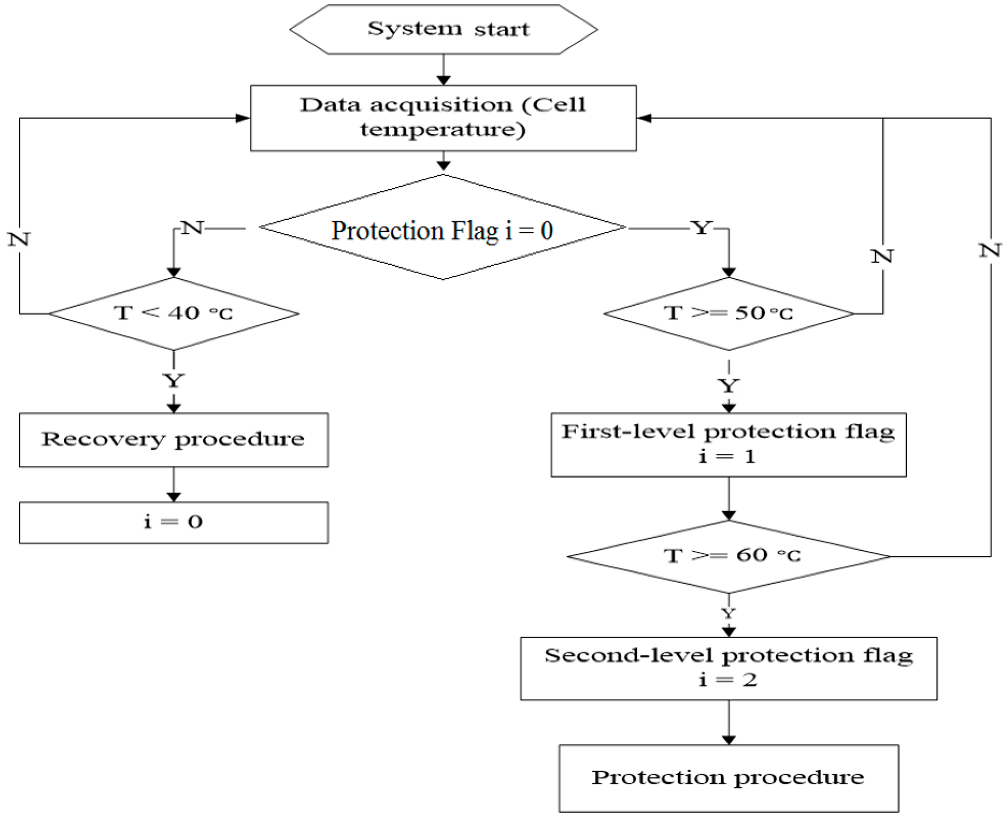
Similarly, over-temperature is another fault to be avoided. In the 12S system prototype, six thermistors are attached to the gaps between every two battery cells to monitor the inner-cell temperatures. A two-level reporting and protection scheme, as well as the self-recovery scheme with a temperature window, are proposed. If the temperature reaches 50 °C, the controller will trigger the first-level protection action to alert the users without interrupting the charging or discharging processes. However, if the cell’s temperature reaches 60 °C (i.e., quite high for a cell), the controller will trigger the second-level protection to stop the charging/discharging process immediately. The controller will trigger the self-recovery process automatically when all the cell’s temperatures drop to 40 °C. The flowchart of the fault diagnosis and protection scheme of over-temperature is shown in
Figure 6. The system will detect the faults mentioned above to allow protection to take place immediately.
2.3.3. Open-Wire Fault Diagnosis
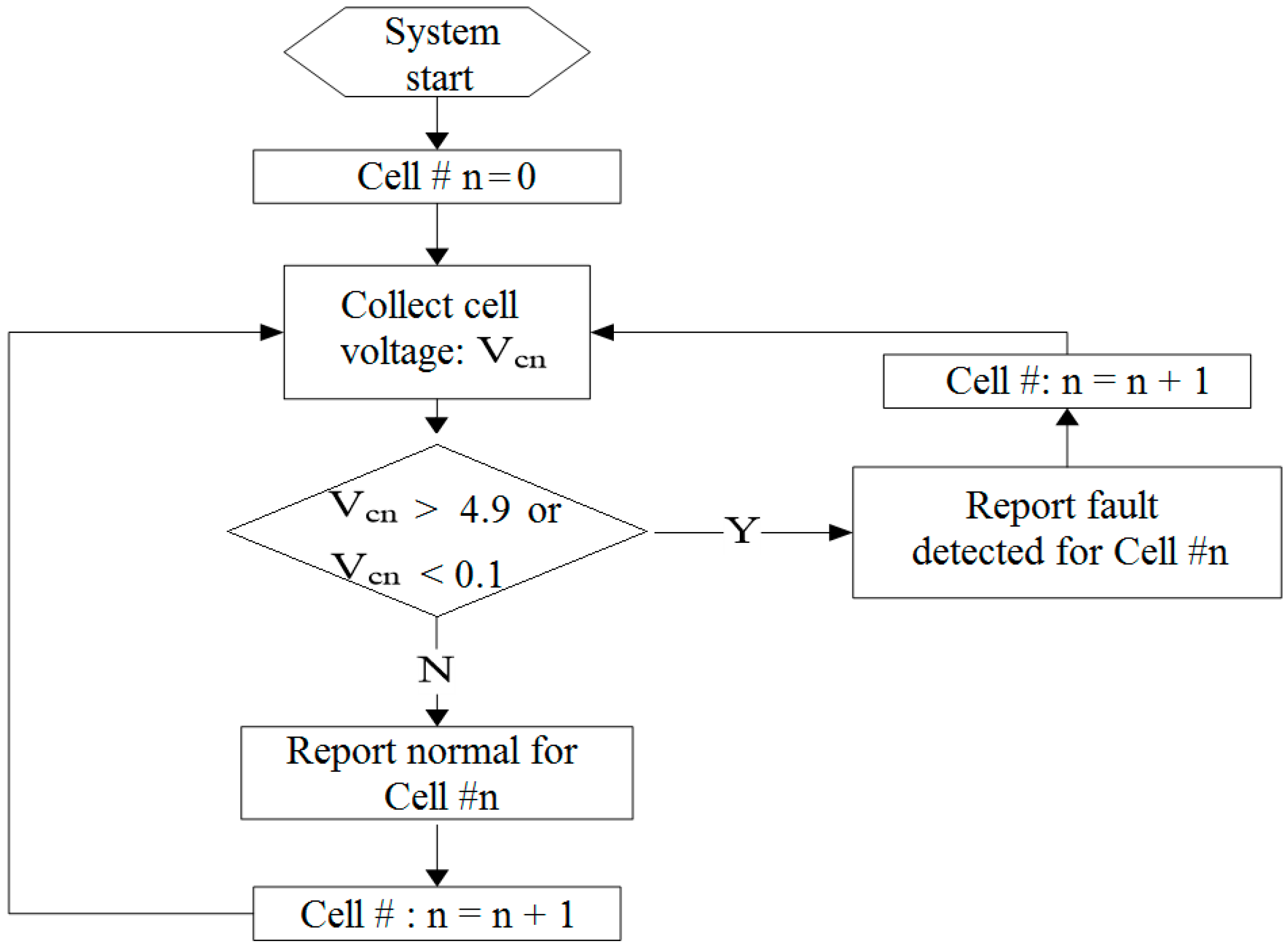
In the multi-cell LIB pack, the voltage of each cell needs to be monitored in real-time. In addition, battery-cell balancing is required for the cells that are unbalanced, that is, when the SOC of one or more cells are unequal. Therefore, there are
n + 1 (
n is the cell number in the battery pack) wires from the cells to the balancing board. It is often difficult to ensure that all the wires are always connected properly during the actual operation. Some of the wires may be loose or disconnected due to frequency impact or vibration from the mechanical structure that encloses the cells. The floating voltage of the LTC6804 input pins will be around 0, or higher than 5 V when the open-wire condition occurs. Based on the floating-voltage sensor, the fault-diagnosis strategy is proposed to diagnose the open-wire fault. The failure will be displayed via the graphical-user-interface (GUI) to alert the user of the fault that requires attention. In this case, it is not possible to automatically connect the wire, as it will require human involvement. The flowchart of the diagnosis strategy can be seen in
Figure 7.
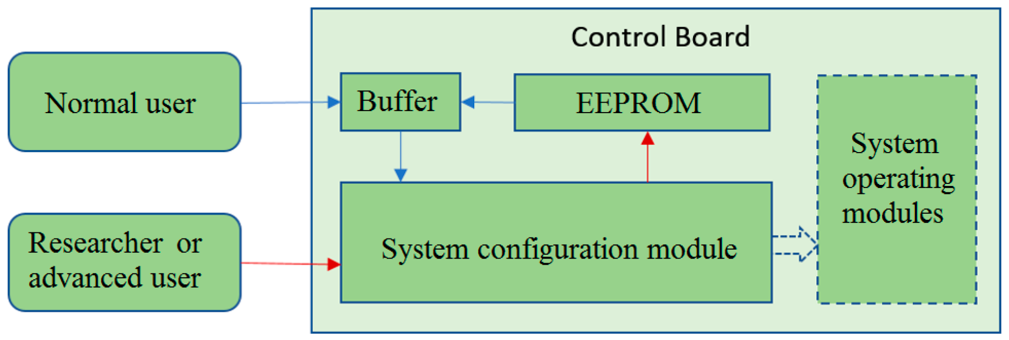
A dual-entrance interface is designed for different users to configure the system for the initial use. Several default parameters for various batteries have been stored in the system memory for ease of operation. The ordinary users do not have to worry about the exact values. Instead, they need to select the types of batteries, the battery-pack grouping information, the battery-cell rated capacity and the maximum discharging current. The system will automatically initialize the corresponding parameters according to the information provided. Currently, four lithium battery types, such as LiFePO
4, Li-ion, LiCoO
2 and lithium polymers, are supported in the proposed system. In addition, the system has an option to customize the parameter values such as protection-voltage level and charging- or discharging-current limitation for further analysis. The entrance design for system parameter configuration is described in
Figure 8.
3. Experimental Results
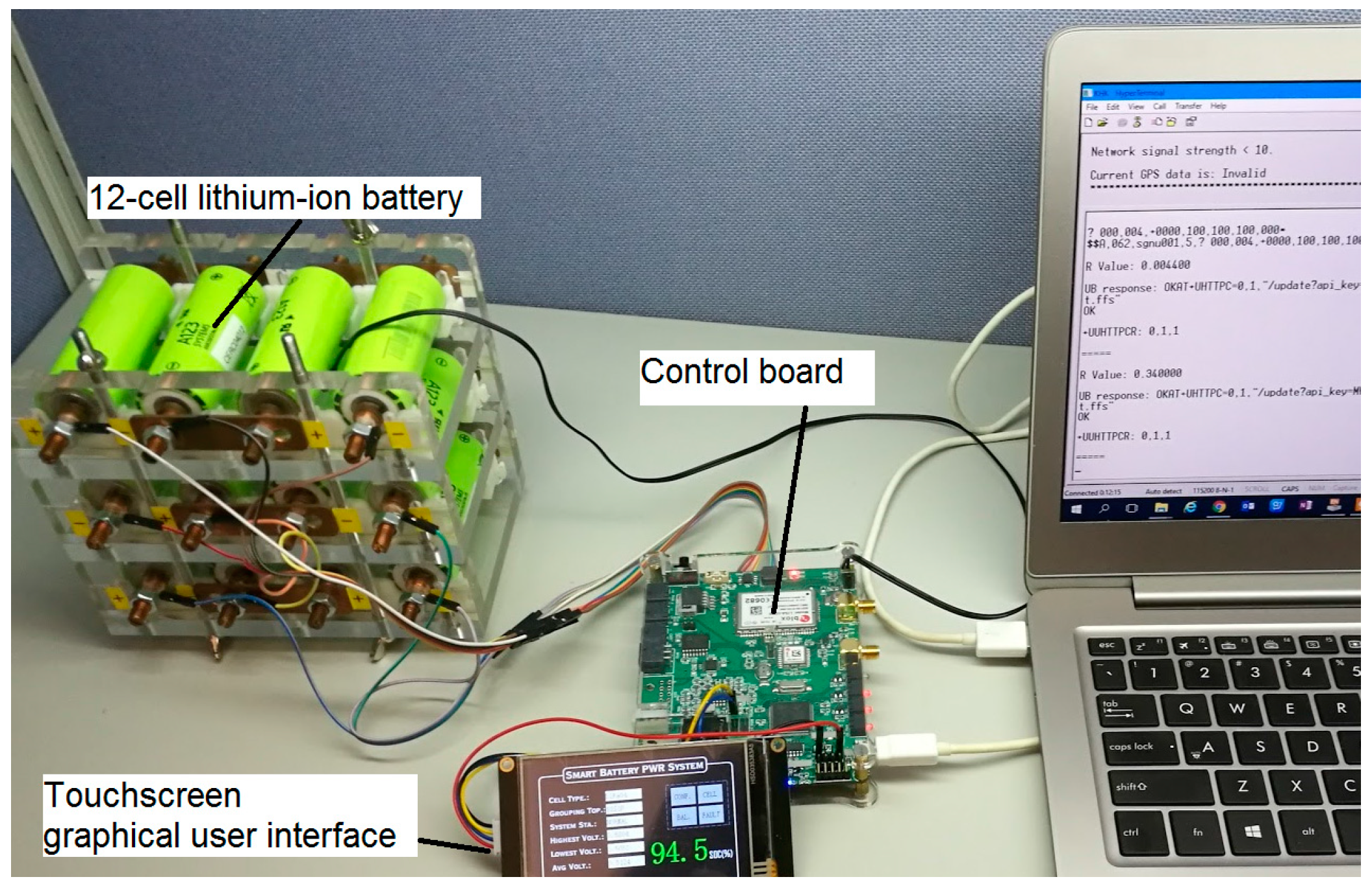
The proposed smart LIB system is implemented as a 12-cell series LIB-pack prototype to test the fault-detection and diagnosis algorithms, as shown earlier. In addition, an actual load profile for an electric vehicle is used to validate the proposed system after the fault-detection and diagnosis algorithms. The overall structure and the physical testing system setups are shown in
Figure 9.
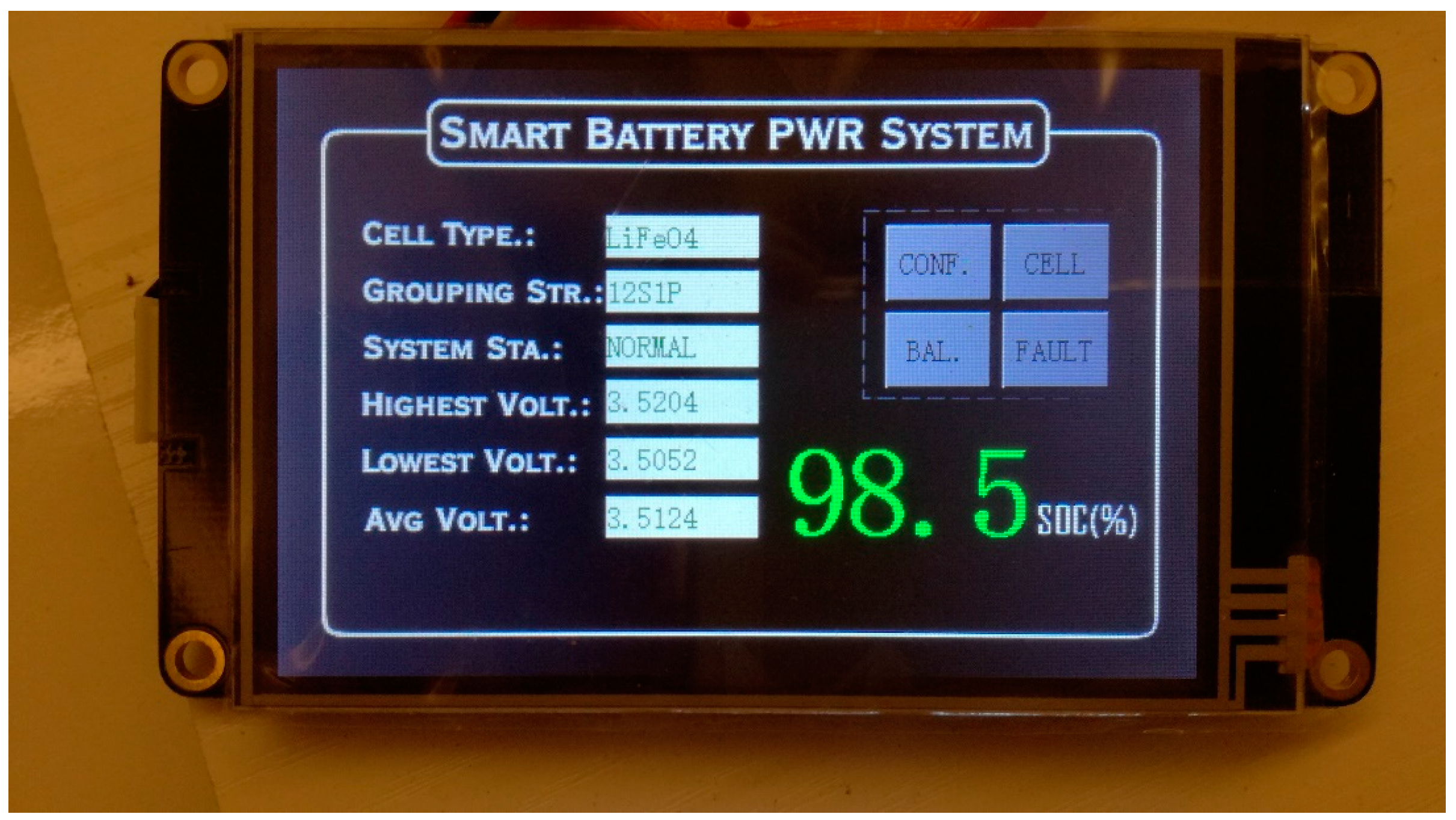
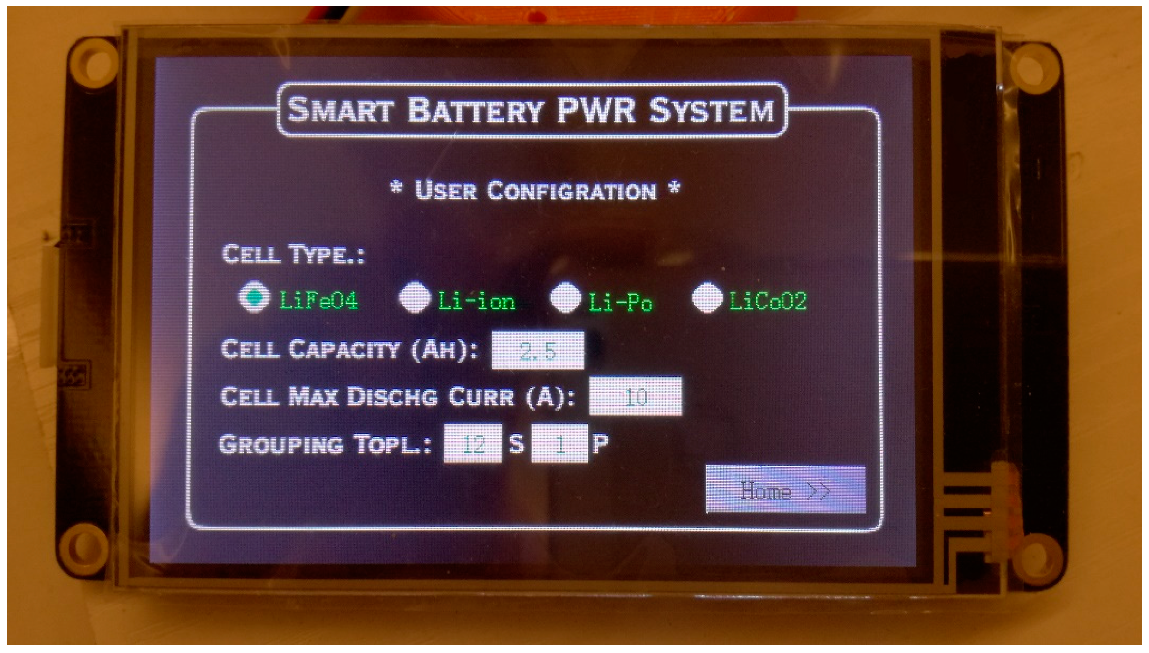
In order to increase the flexibility of the power system, the proposed battery-power system provides a touchscreen LCD interface for users to configure the battery-power system. It consists of parameters such as battery-cell type, battery-cell rated capacity, maximum discharging current and battery-pack grouping topology for the battery pack during the first initialization. This open feature enables the controller to adapt to various types of the battery cell and different topologies. The front page of the GUI is shown in
Figure 10, while the user’s configuration page can be seen in
Figure 11.
The front panel in
Figure 10 contains information such as the current configuration of the battery pack and the respective minimum, maximum and mean voltages and SOC value of the battery pack. The other functional modules that contain the cells’ information are shown in
Figure 10. In the configuration page, as shown in
Figure 11, four options of the battery-cell types can be selected. The users can choose the material of the physical cells connected to the control board, the battery-cell capacity and battery-cell maximum discharging current. The last parameter is the grouping topology of the battery pack that depends on the physical battery-cell layout, that is, series or parallel. The system can be initialized to proceed with the proper function and fault diagnosis operation. However, if the series-cell layout is defined by the actual parallel-cell configuration, the system will not function for safety purposes.
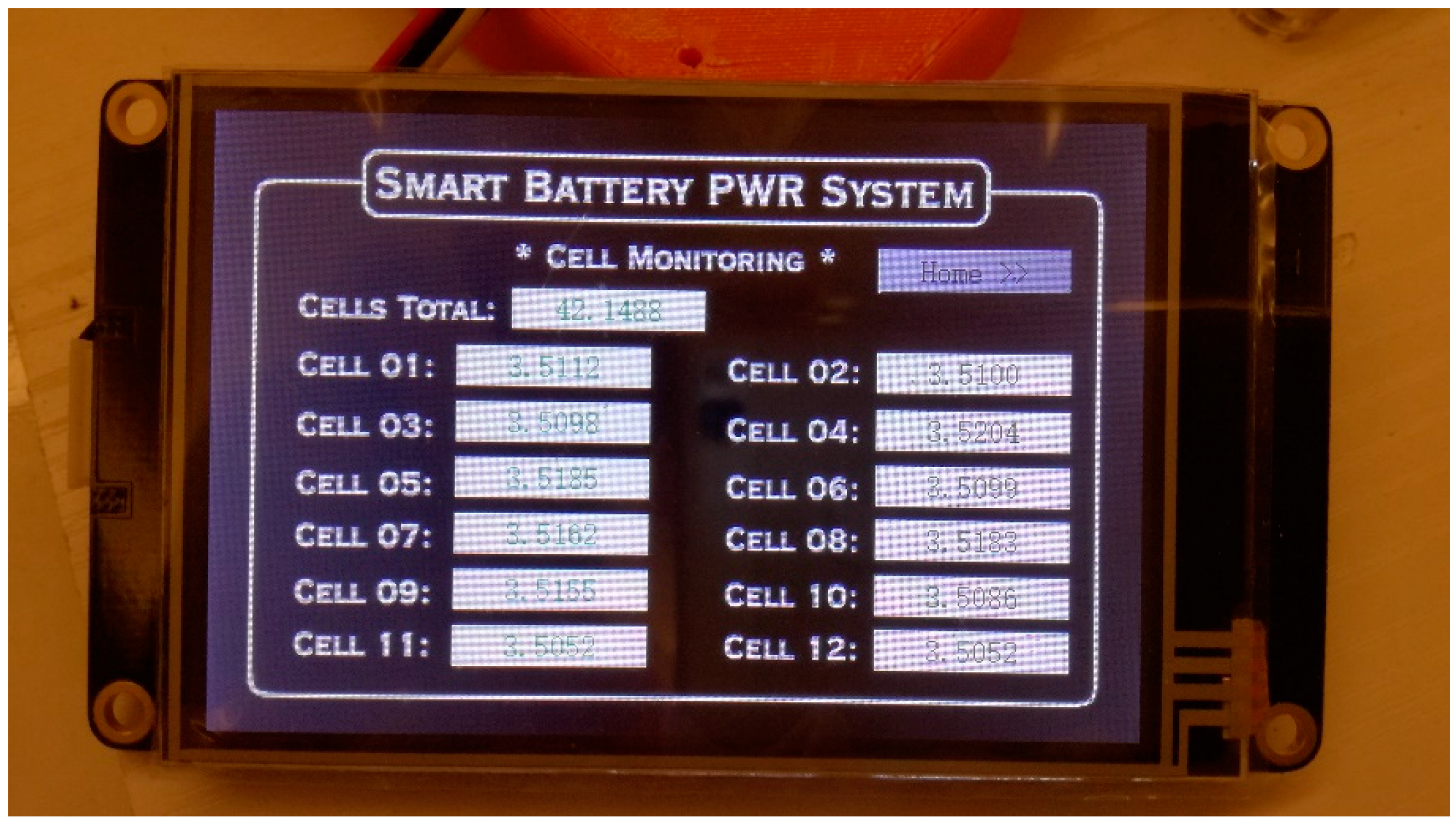
The data-acquisition module of the power system is essential for the SOC estimation and fault diagnosis. It will affect the overall performance of the system. In this paper, an accurate data-acquisition module for the battery cell is implemented with a total measurement error of less than 1.2 mV. The precise data ensure that the accuracy of the SOC estimation and the safety of the system can be monitored. The cell-monitoring page of the GUI can be seen in
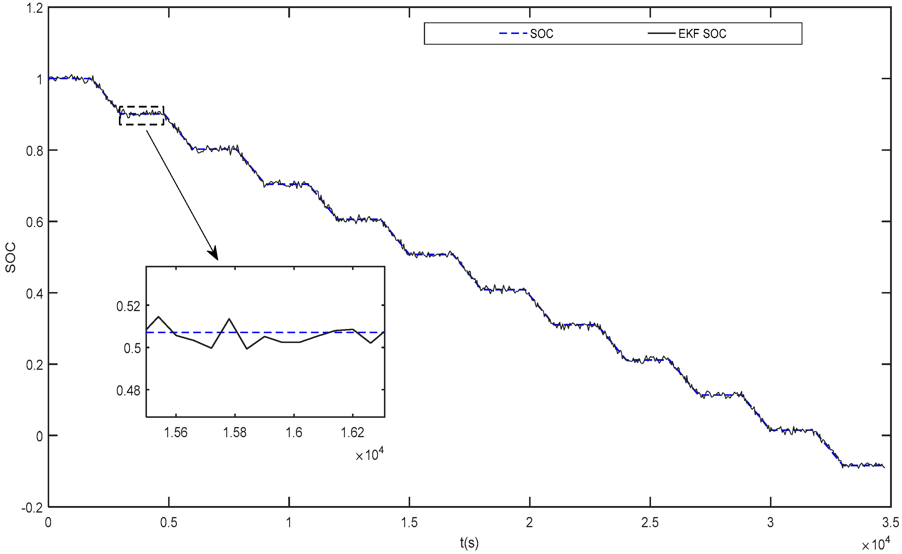
Figure 12. For example, the system can estimate the SOC of each cell. The SOC values are quite close to the values obtained by the extended Kalman filter (EKF). The proposed SOC estimation exhibits a close match with the EKF under the regular pulse discharge test (PDT), as seen in
Figure 13. Here, the 2 Resistor-Capacitor (RC) equivalent circuit model (ECM) is applied for the EKF-based SOC estimation. The function of the SOC with respect to
is described as follows [
33]:
where
.
A detailed battery modeling and EKF-based SOC estimation can be found in the reference [
33]. Note that the proposed battery system can also allow different SOC-estimation algorithms to be programmed and compared.
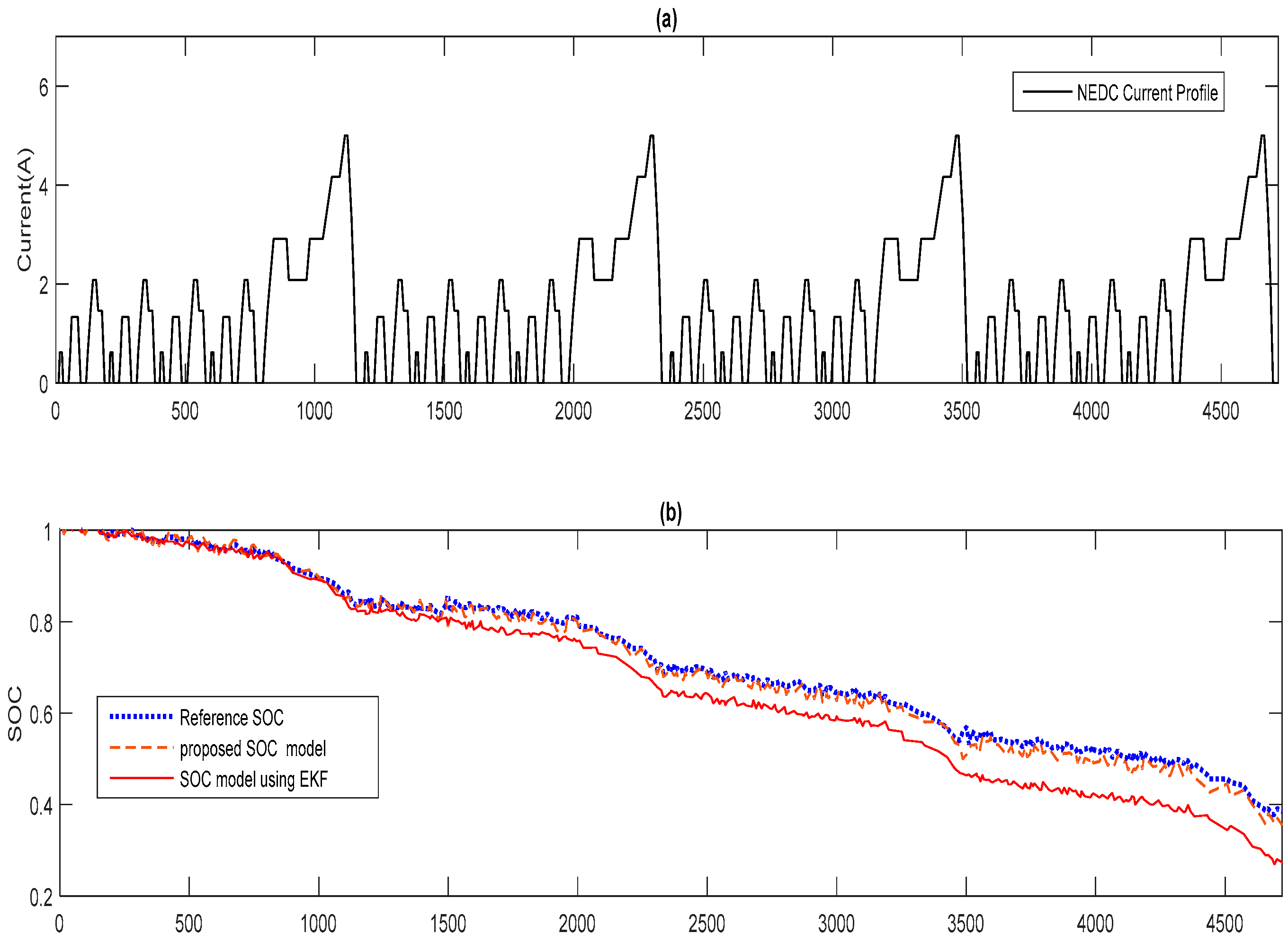
To further validate the proposed SOC-estimation algorithm under realistic and dynamic situations, the New European Driving Cycle (NEDC) load profile for a typical electric vehicle was applied to the 12-cell series battery-pack prototype to simulate the electric vehicle applications under the ambient temperature effect and compared with the standard EKF-estimation approach. The NEDC load profile is shown in
Figure 14a, subjected to the ambient temperature. It is worthy to note that the load profile had been scaled down to fit the battery pack. The programmable DC electronic load was used to run the pre-programmed NEDC load profile. Before the experiment, the battery pack was fully charged to obtain an initial SOC of 100%. The calibrated Ampere-hour (Ah) data reading from the equipment was used as the reference. As shown in
Figure 14b, the SOC estimation of the proposed SOC model can follow the reference SOC robustly. Despite the load profile changing drastically, the SOC error can rebound after a short period of drift. On the other hand, the SOC-estimation result from the EKF-based SOC model drifted away after several test cycles. In summary, under the NEDC test profile, which is used to simulate the load in reality, the proposed SOC-estimation method performs better than the EKF-based method.
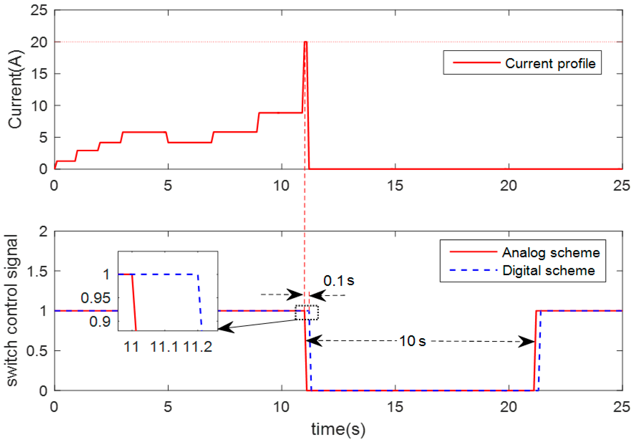
After the SOC estimation was validated, the dual diagnosis and protection schemes were tested under different fault conditions. In the 12-cell series battery-pack system, the maximum current of the battery cell was set to 10 A with a maximum delay of 10 s after the fault is detected. This provides limitations on the current and the time delay used in the fault diagnosis. Note that these values can be adjusted.
Figure 15 shows the fault-detection and self-recovery curve. Once the external short-circuit occurred, the analog scheme detected the fault within a very short time and generated a protection signal to turn off the discharging switch, as shown in
Figure 15. It took around 100 ms before the fault was detected. Thus, the result shows that the external short-circuit fault can be detected and the system can later recover from the fault.
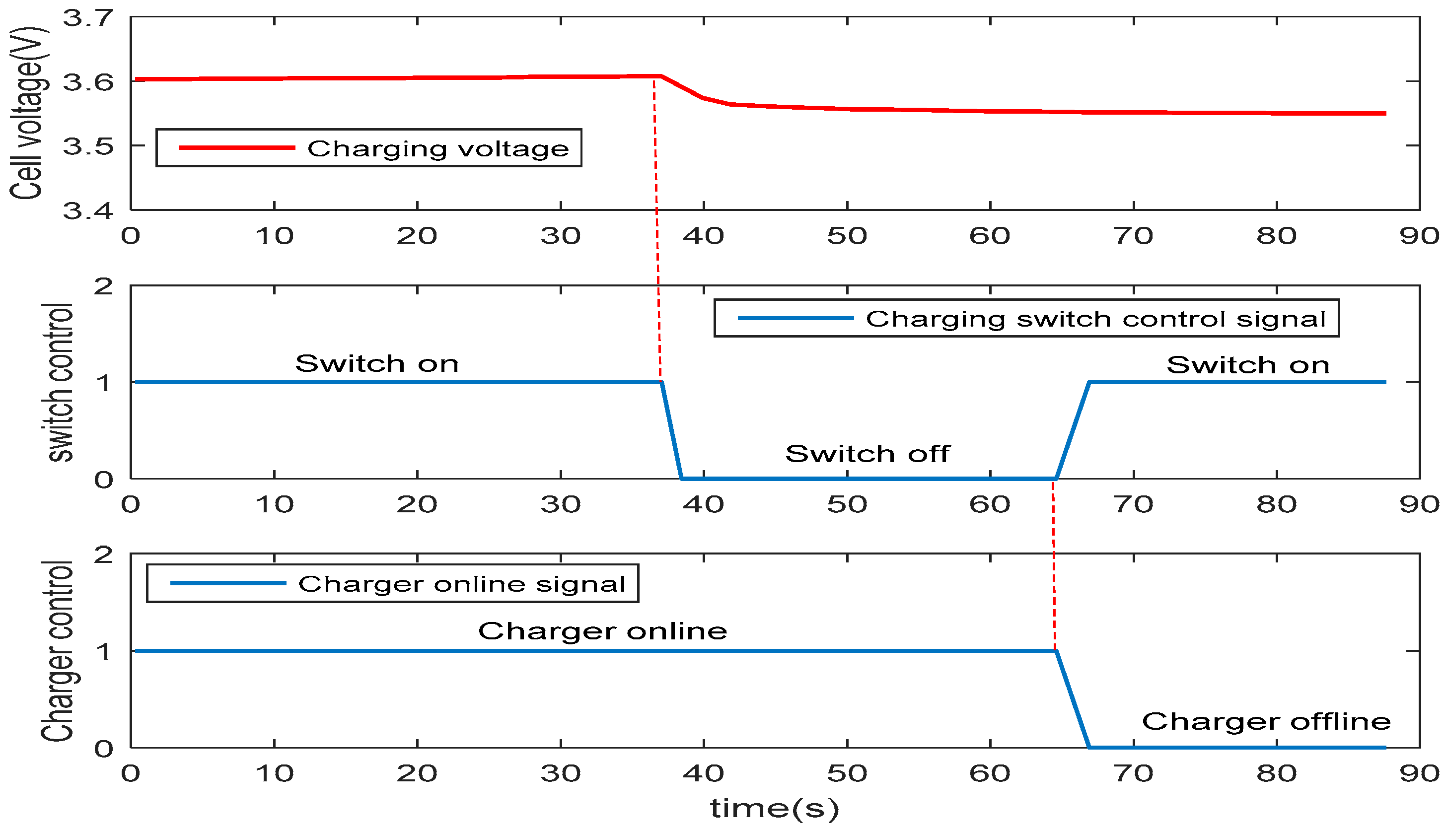
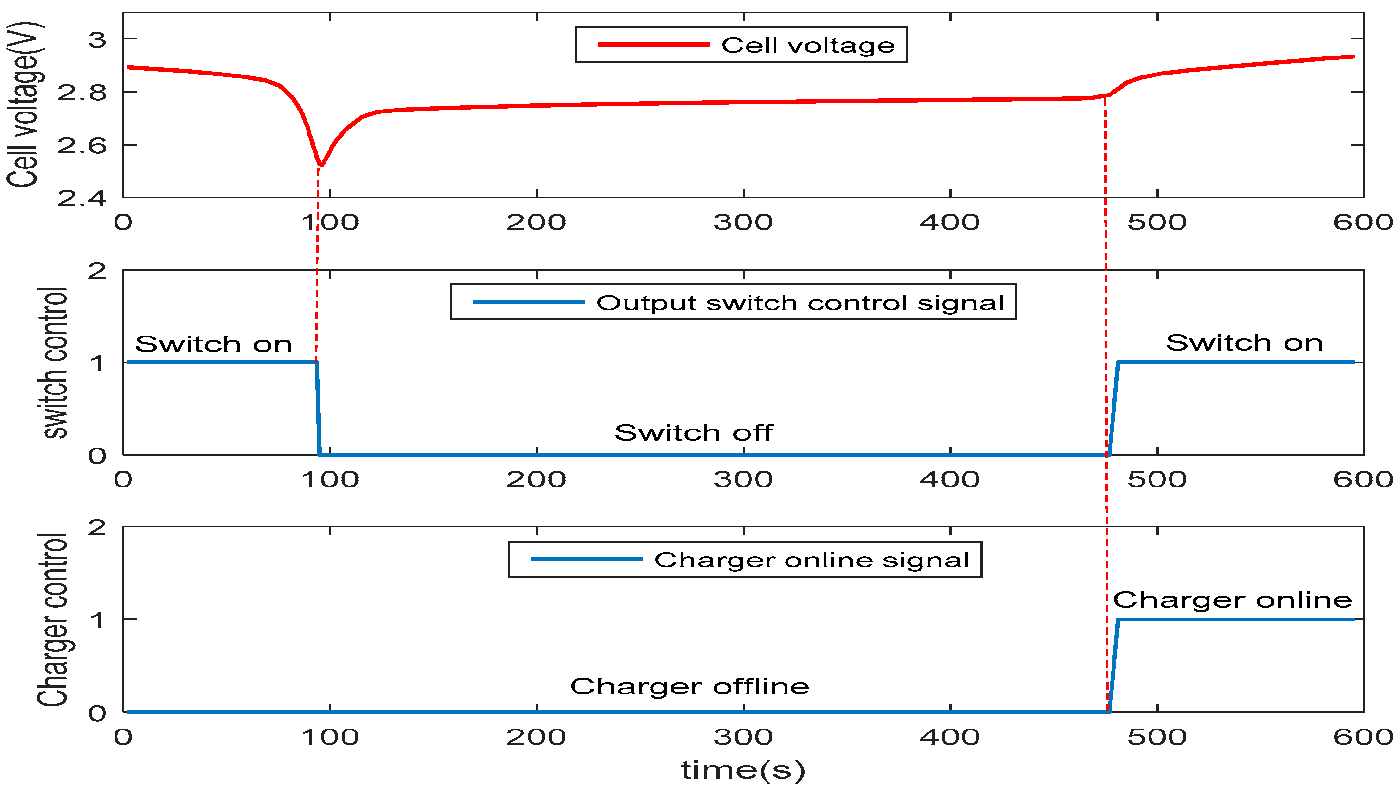
The over-charged and over-discharged states are another two faults that can cause permanent damage to the internal structure of batteries. In the prototype system, over-charged and over-discharged fault-diagnosis schemes are both integrated. The protection and self-recovery processes can be seen in
Figure 16 and
Figure 17, respectively. As observed in
Figure 16, after the batteries were fully charged, the over-charged fault was reported, and the charging switch was turned off by the controller to isolate the charging module from the cells. To trigger the charging function, the charger needs to be removed to allow the charging module to recover automatically. Similarly, the over-discharged fault was detected when any cell of the battery pack reached the cut-off voltage, as shown in
Figure 17. The discharging switch was turned off to isolate the battery from the output module or load. Using the self-locking and self-recovery function, the over-charged and over-discharged faults can be managed effectively to prevent damage to the batteries and possible injury to the user. Similarly, over-current, over-temperature and broken-wire fault diagnoses of the battery system were implemented using the proposed schemes in the actual battery-power system.


