Abstract
This paper offers a wide overview on the large-scale electrochemical energy projects installed in the high voltage Italian grid. Detailed descriptions of energy (charge/discharge times of about 8 h) and power intensive (charge/discharge times ranging from 0.5 h to 4 h) installations are presented with some insights into the authorization procedures, safety features, and ancillary services. These different charge/discharge times reflect the different operation uses inside the electric grid. Energy intensive storage aims at decoupling generation and utilization since, in the southern part of Italy, there has been a great growth of wind farms: these areas are characterized by a surplus of generation with respect to load absorption and to the net transport capacity of the 150 kV high voltage backbones. Power intensive storage aims at providing ancillary services inside the electric grid as primary and secondary frequency regulation, synthetic rotational inertia, and further functionalities. The return on experience of Italian installations will be able to play a key role also for other countries and other transmission system operators.
1. Introduction
This paper is an overview of the large scale electrochemical storage stationary installations in Italy. Many previous papers [1,2,3,4,5,6,7,8,9,10,11,12,13,14,15,16,17,18,19,20,21,22,23,24], which are briefly reported in the following, highlighted the role of Italy as a path-maker in the field of large scale electrochemical storage in the high voltage network. In [1,2,3], a detailed description of the Italian energy intensive installations can be found, whereas papers [4,5,6,7,8,9,10] offer some analyses of the main features of sodium-sulphur technology. Paper [15] thoroughly analyses the authorization procedures of Italian energy storage systems. In the papers [11,12], the reader can find scientific and technological details of the sodium nickel chloride batteries of the Italian installations whereas papers [13,19] are devoted to a steady-state electric model of this technology; in [20,21] this model has been enlarged to take transient behaviour into account. Safety tests performed on a Na-NiCl2 battery are fully presented in [22,23]. Papers [16,17] consider the model of battery under faulted condition and their arc flash respectively. Paper [18] is devoted to the computation of battery efficiency including auxiliary equipment losses.
The main contribution of this paper is to thoroughly present all the features of these installations. In particular, the paper describes how the Italian transmission system operator (TSO in the following) has chosen two energy storage strategies in the high-voltage network. In the first one, the electrochemical energy storage systems (EESS) is conceived to release renewable generation from electric loads and to avoid overload conditions in the existing overhead lines. This use implies longer charge/discharge intervals (about 8 h) and a kind of “energy service” more than a “power service”; therefore, these installations have been called “energy intensive” installations. For Italian “energy intensive” installations [1,2,3], Terna was chosen because of its extensive history of successful installations, the Sodium-Sulphur (Na-S) electrochemistry [4,5,6,7,8,9,10], supplied by the Japanese NGK INSULATORS, LTD. There have been three installation sites located in the South of Italy (around Benevento city): two installations of 12 MW and one of 10.8 MW (wholly 34.8 MW Na-S storage has been installed). It is worth remembering that Na-S batteries belong to the Na-beta battery family (as Na-NiCl2 [11,12,13]). The other direction has involved electrochemical technologies with short charge/discharge intervals (from 0.5 to 4 h). The tested technologies are in the Li-ion family and sodium-nickel chloride. The installation sites are Sardinia (9.15 MW installed power in Codrongianos) and Sicily islands (6.8 MW installed power in Ciminna). Due to their high use flexibility allowed by the Power Conversion System (PCS) [14], power intensive installations have been applied in the field of grid ancillary services. Moreover, a brief cost comparison is also presented in Section 5.
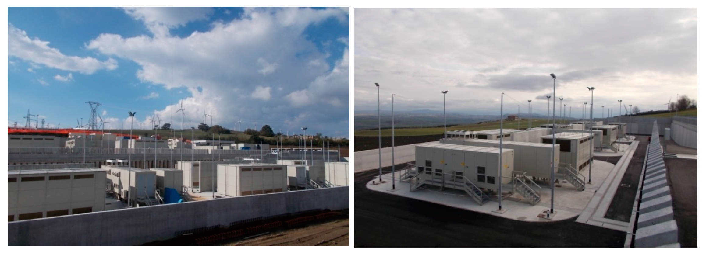
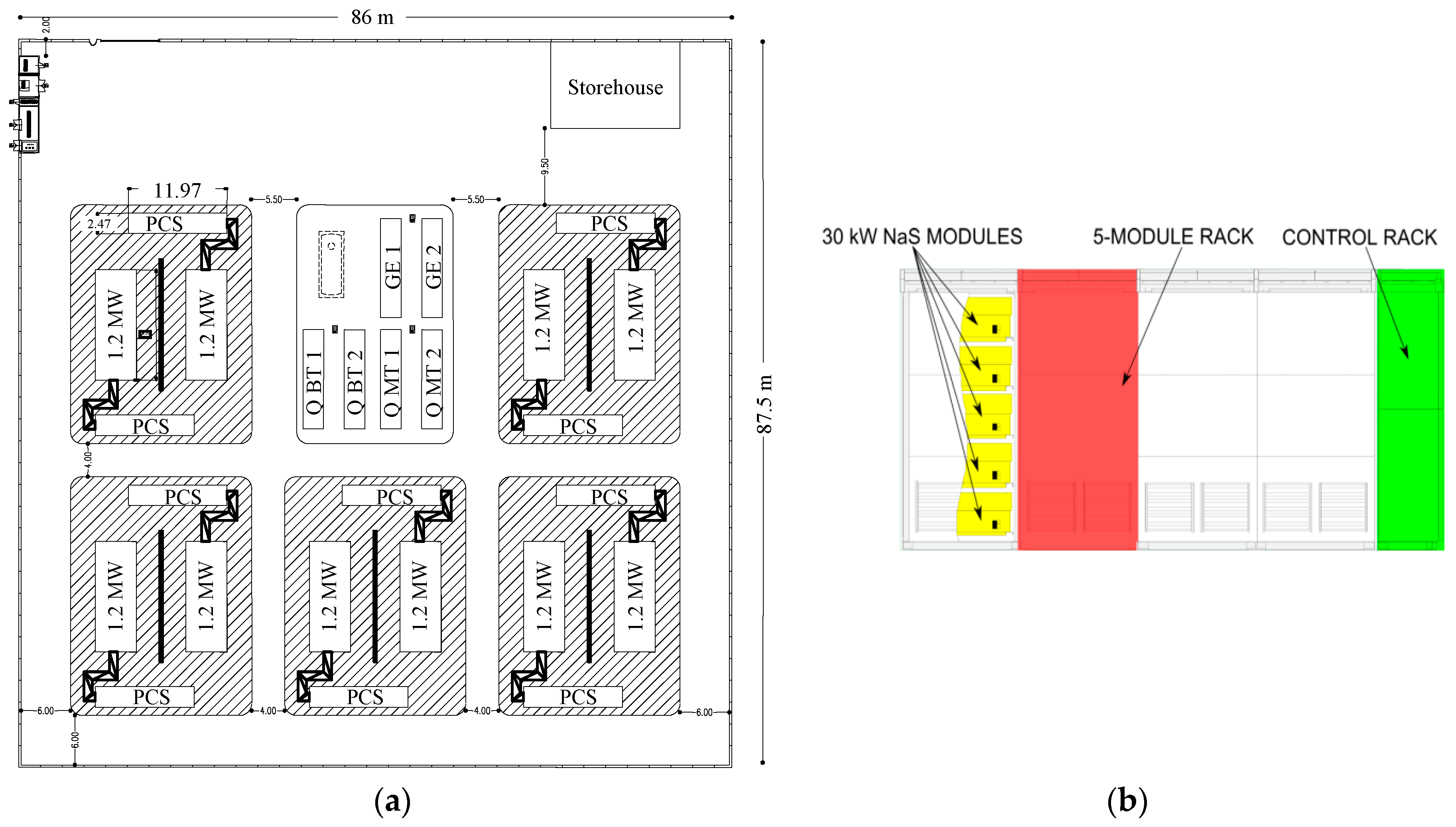
2. Energy Intensive Projects
The three energy intensive installations are very similar. A unit makes use of module series and parallel connection. A 12 MW installation extends over an area of 7000 m2, and involves the use of medium (20 kV) and low (400 V) voltage levels, in detail (see Figure 1a):
- ➢
- 10 units of 1.2 MW each;
- ➢
- 10 Power Conversion Systems (PCS) of 1.2 MW (in other Italian installations, there are 2.4 MW PCS instead of 2 PCS of 1.2 MW);
- ➢
- 2 shelters for MV switchboards (QMT1, QMT2);
- ➢
- 2 shelters for LV switchboards (QBT1, QBT2);
- ➢
- 2 shelters for emergency generators (GE1, GE2);
- ➢
- Shelter for the control system.
Figure 1.
(a) 12 MW installation constituted of 10 units of 1.2 MW; (b) Frontal view of the 1.2 MW unit (the other four racks are back-to-back with the visible ones).
The connection of the power systems to the national grid is performed by means of a MV/HV (20/150 kV) transformer. The HV level is 150 kV since all the energy driven installations are located in South Italy (in North Italy, the HV level is 132 kV). The Italian unit, also called “assembly”, has a rated power of 1.2 MW with 40 modules of 30 kW (see Figure 1b). The structure is composed of a self-supporting latticed frame with shelves for module placement, a Battery Management System (BMS) container part, ventilation, and a cooling system. Each module is protected by a BMS. The BMS includes a disconnection relay that disconnects the battery from any load if the value of any battery parameter is outside the predefined operating range.
The controlled parameters are the module temperature, the dc-side current and voltage. The battery status is calculated from these basic parameters. Other BMS functions include: detection of alarms, warnings and battery capacity limitation signals; Control interface with PCS and data logging. The frame is of galvanized steel. The frame thickness is at least 2.3 mm both on lateral sides and on the covering. The dimensions (in meters) are 9.410 length × 4.800 depth × 4.820 height. It is worth noting that the standard NGK unit had five modules of 50 kW per rack (i.e., 250 kW per rack) whereas in the Italian installations five modules of 30 kW (150 kW per rack) have been employed: this gives greater spacing between modules. The Terna assembly is also equipped with a double redundant fire and gas detection system: the first is based on SO2 detection (in extremely remote case of fire and cell breaking), the second is based on ventilation system continuous air analysis that can detect the possible presence of smoke. Figure 2 shows some photographs of the energy intensive installation in Ginestra.
Figure 2.
Some photos of Italian Na-S “energy intensive” installation in Ginestra.
2.1. Safety Features
In order to have a general overview of safety features, Table 1 reports all the safety levels which have been implemented in Italy. An additional protection for SO2 confinement has been realized: it consists of an automatic system for ventilation block by means of ventilation grid shutting (based on SO2 detection) with the dual effect of avoiding the access of oxidizing agents and the SO2 spreading. It is worth noting that, once running, the heat produced by charging and discharging cycles is sufficient to maintain operating temperatures and no heaters are required. Heaters are in operation only when the battery is idle and the temperature falls below 305 °C. In any case, if the battery is not running and the heaters fail, the temperature tends to decrease. It is not an issue of safety but only a matter of battery performance degradation. The battery has a very good thermal insulation and the worst thing which can occur (if for a long time the heaters do not work) is that the molten substances solidify. The battery can withstand 10 cycles (the so-called freeze-thaw cycles) with temperature lower than 150 °C.
Table 1.
Safety levels of the Na-S unit starting from the cell level.
2.2. Tests Performed by NGK on the New Italian Module
In recent years, a lot of tests have been performed on the most used module, i.e., on NGK E50. As already mentioned, Terna has required a safety enhanced module with the same dimensions as the previous one but with fewer cells inside, with more sand between cells and with fire resistant carbon sheets inside the module. It is therefore inferable that all the results obtained in the tests on the “old” module would give equal or better results than the new one. This has been confirmed by some tests commissioned by Terna whose results are reported in Table 2. In particular, in order to verify the effectiveness of sheets inside the cell a test has been performed: the cells adjoining to that fired are not damaged so that no fire propagation has occurred inside the module. Another test has been performed in order to verify the effectiveness of the sheets inside the module: the fire has not propagated outside the module.
Table 2.
Safety Tests performed by NGK on the new module.
2.3. The Authorization Procedure
The authorization procedures have been wholly presented in [15]. The most important European regulation which can be applied to the stationary application of sodium batteries is the Directive 96/82/CE, also known as “Seveso II”, and the Directive of the European Parliament 2012/18/UE also known as “Seveso III”, both concerning the major-accident hazards related to the presence of hazardous substances. It is worth noting that each EU member state had to incorporate the provisions of the “Seveso III” directive into national law by 31 May 2015. In order to evaluate the Seveso II implications, the entire amount of chemical substances (during charge and discharge and consequently sodium, sulphur, and polysulphides) in the energy storage installation project has to be determined. By considering the toxic substance amounts as the most restrictive ones, it is possible to demonstrate that up to a rated power of 12 MW the installation falls under article 6 prescriptions of Legislative Decree 334/99, which represents the Italian decree in force during the period when the evaluation of Terna projects was made by the competent authorities. These prescriptions foresaw to send a notification of the installation of the three sites to the competent authority for assessing the risk of major accidents (offices “relevant risks and integrated environmental authorization” of the Ministry of Environment, of the Region, of the Provinces and territorially competent Municipalities, Provincial Prefecture, the “Regional Technical Committee of the Fire Department”) at least 180 days before the start of construction, together with:
- ➢
- A detailed project information;
- ➢
- A Risk Analysis Assessment (performed in collaboration with the Department of Industrial Engineering of Padova University), which showed that, in case of occurrence of given events (earthquake and vibration, flooding, mishandling, direct and indirect lightning strikes, endogenous or exogenous fire, sabotage and hunting, and external impacts), the safety/mitigation systems adopted in the plant would have reduced the risk of release of chemicals in the environment to negligible values. The tools used in the risk assessment have been the FMEA (Failure Modes and Effects Analysis) and the FMECA (Failure Modes and Effects and Criticality Analysis). In a range between 1 and 25, the maximum computed risk priority number has been 9.
Furthermore, Terna, in accordance with the EU Directive “Seveso”, has drafted an internal document called “Prevention Policy for Major Accidents”, holding the management criteria to be undertaken for the prevention of “significant” accidents.
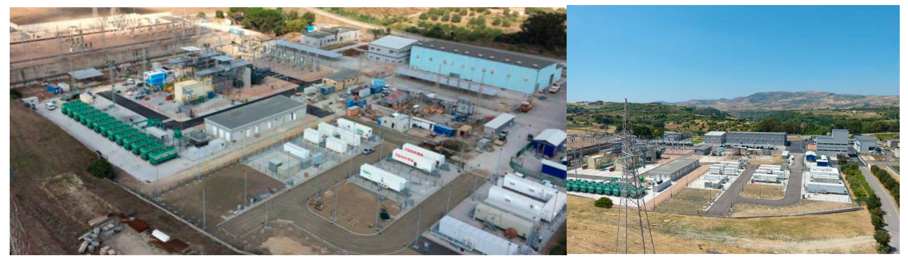
3. Power Intensive Projects
In the following, a detailed description of the power intensive installations and of their uses inside the high voltage network are presented. These installations have also been named “Storage Labs”.
3.1. Ciminna (Sicily) and Codrongianos (Sardinia) Power Intensive Installations
Since the power system architecture of the two installations is very similar, only Codrongianos Storage Lab is described (see Figure 3). Its single-line diagram is shown in Figure 4. In Figure 5, some photographs of the HV/MV transformer and battery unit racks are shown. The different power ratings, and the different storage typologies are reported in Table 3 (in Table 4 for Ciminna). There are 10 different EESS branches, subdivided in two groups of five (three branches are foreseen for future storage technologies). Each EESS has its own PCS (composed by four 250 kVA rated power inverters), step-up LV/MV transformer (1.25 MVA, 15 kV/0.55 kV, Yd connected) and a dedicated MV cable line [16]. The 15 kV bus bar is then connected to the 150 kV HV ac sub-transmission grid through a 40 MVA, 150 kV/15.6 kV transformer shown in Figure 5 (Yy connected). A grounding transformer (GT) with a 385–770 Ω resistor (depending on the temperature) provides a ground path for the otherwise ungrounded 1.7 km long MV system connected to the 15 kV bus bar. PCSs are fully described in [14]: generally, PCS is constituted of a first stage made by a DC–DC converter and of a second stage made by a DC–AC converter to maintain the inverter dc side voltage. Moreover, this two-stage architecture avoids the PCS oversizing due to the EESS voltage variation during the charge/discharge operations. In fact, a Δu% percentage EESS voltage variation with respect to the rated value requires an inverter component overrating of 1 + Δu% for both the voltage and the current (maximum current corresponding to minimum battery voltage), resulting in an inverter power oversizing of about 1 + 2 Δu%. For instance, by hypothesizing a maximum current and voltage variation of 20% (ΔVmax and ΔImax respectively), the inverter rated power must be oversized of 40% as in the following:
P = ΔVmax·ΔImax = Vn(1 + 20%)·In(1 + 20%) ≈ 1.40 Pn = Pn + ΔP
Figure 3.
Two views from above the Codrongianos substation.
Figure 4.
Single-line diagram of Italian “power intensive” installation (Storage Lab) in Codrongianos.
Figure 5.
Some photos of the Italian “power intensive” installation (Storage Lab) in Codrongianos.
Table 3.
Different storage technologies installed in Codrongianos (Sardinia).
Table 4.
Different storage technologies installed in Ciminna (Sicily).
For these Storage Lab installations, some features have been studied and published; in particular:
- ➢
- modelling of battery under faulted conditions and assessment of protection system behavior [16];
- ➢
- the arc-flash in these energy storage systems [17];
- ➢
- the efficiency calculations including auxiliary power losses [18];
- ➢
- the steady-state and transient modelling of Na-NiCl2 [13,19,20,21], including safety tests [22,23].
3.2. Power Intensive Ancillary Services and Advanced Functionalities
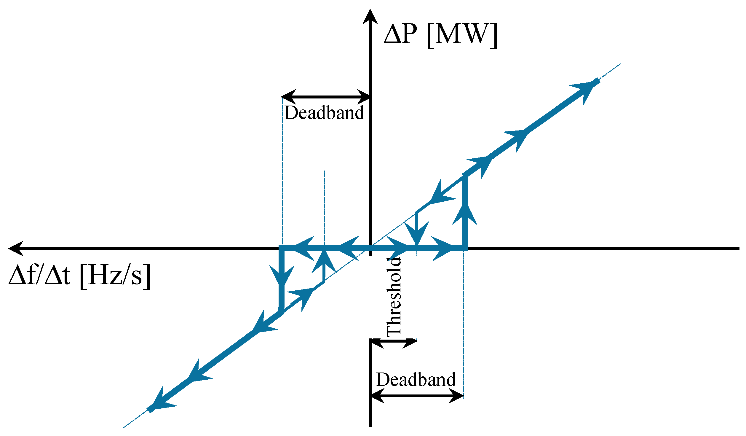
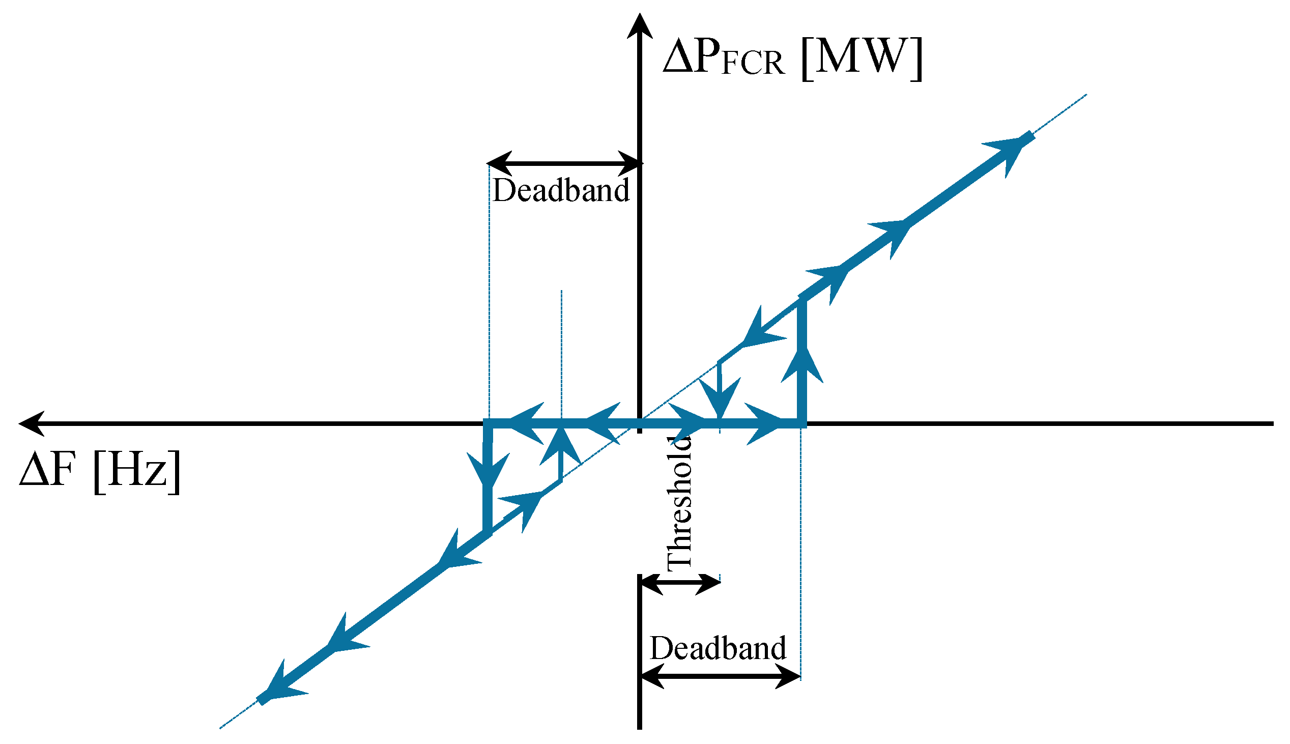
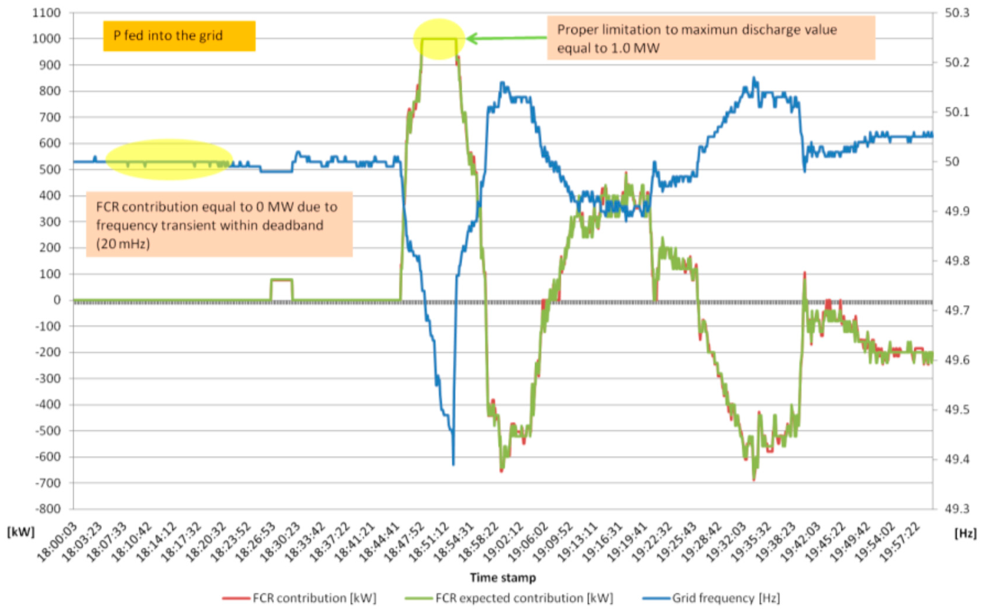
3.1.1. Primary Frequency Control: Provision of Frequency Containment Reserve (FCR)
This service [24] is delivered in accordance with the Italian Grid Code (Annex 15 of [25]) and requests EESS to modulate the active power output (ΔP, in MW) proportionally (depending on the droop parameter, σ, expressed in % and fully configurable) to the deviations of the grid frequency (ΔF, in Hz) around its nominal value of 50 Hz, as in (1):
Figure 6 shows the FCR service regulation patterns.
Figure 6.
FCR ancillary service regulation patterns.
EESS may shift the active power flow direction continuously and take less than 100 ms for a complete inversion (full inversion from maximum discharge active power to maximum charge one) as shown in Section 4. The value of the droop parameter σ may be set to a small value in order to allow EESS to perform a greater active power contribution in case of wide frequency deviations. This service will play a key role since in the European grid there is an ever-growing decreasing of power frequency characteristic of primary control (also known as regulating energy) due to the increase of generation by renewable resources [26].
3.1.2. Secondary Frequency Control: Provision of Frequency Restoration Reserve (FRR)
In accordance with the secondary frequency control [24], this service consists in performing active power output variation ΔPFRP as requested by an external control signal (L%, whose percentage range is 0–100%) fed to local control system from Terna Central Supervisory Control And Data Acquisition (SCADA). It is worth remembering that FRR regulation is a power plant service. A reserved regulation band (half-band, HB, expressed in MW) around the active power set-point (the actual balancing program or the stand-by mode) is dedicated in accordance with:
As already mentioned, the percentage set-point control signal L% is forwarded by Terna to the plant and it is defined in the range of 0–100%. Set-point signal is updated and forwarded every 8 s to the plant with a maximum variation within the total regulation band of 4%.
3.1.3. Provision of Synthetic Rotational Inertia (SRI)
In addition to FCR, EESSs could be equipped with SRI (operated independently from FCR) [24] in order to contribute in reducing the fastest frequency transient phenomena, since the beginning. The EESS high rapidity of varying the generated or absorbed active power P has made feasible several scenarios which were not possible with traditional power plants. In the specific, these EESS characteristics may help mitigate the reduction of European grid rotational inertia: therefore, EESS may be requested to deliver an active power proportionally to the measured derivative frequency, i.e., to the rate of change of frequency (df/dt). However, it is crucial to implement robust control blocks for a reliable frequency rate of change sampling. This could be fulfilled by feeding the control block numerical algorithm with a proper and adequate frequency sampling, insuring on one hand computational accuracy and on the other hand fast solution times. The result must be available within a time frame assessable in tens of milliseconds. The faster the P response, the more effective the mitigation of frequency variation is. Such a P response should not be confused with a fast FCR regulation set with low droop value because its contribution depends linearly on the instantaneous measured frequency deviation. By assuming both FCR and SRI committed together, each contribution must be distinguished: EESS may be engaged in FCR with droop not sufficient to let the plant fill the P capability though still guaranteeing fast response, and at the same time SRI may provide EESS full P capability access just in case of sudden frequency deviation. EESS has to deliver ΔPSRI (in MW) proportionally (depending on a parameter, KW, expressed in MW·s/Hz and fully configurable) to the filtered derivative frequency measurement (Δf/Δt, in Hz/s), as in (3):
Figure 7 shows the SRI service regulation patterns.
Figure 7.
SRI ancillary service regulation patterns.
The necessity to implement such a service is to emulate the stabilizing contribution to frequency deviations guaranteed by the rotating masses, in prevision of an ever-growing passage from traditional power plants (with rotating synchronous generators) to static inverter-equipped power generation. For a prompt SRI response, it has been crucial to implement a reliable, accurate, and fully configurable digital filter of grid frequency for feeding the regulator: Infinite Impulse Response filters (IIR—e.g., Butterworth filters) have been selected as the best compromise between speed and accuracy of response. IIR filters are fully configurable in terms of filter order and cut-off frequency to adjust filtering to the effective harmonic content inside grid frequency and to achieve an adaptive filtering by means of high stopband attenuation and effective noise cancellation. In addition, IIR filters enable the achievement of low-rate phase delays and may be designed as inherently stable.
3.1.4. Congestions Mitigation and Balancing Program
HV line congestion mitigation/active power balancing service [24] is used to set a specific active power profile to EESS through XML file or with a manual set-point. As long as this service is activated, other active power regulations (FCR and FRR regulations), whenever turned on, must provide their contribution around this active power profile. In the case of active power balancing service deactivate, reference power is zero MW and all other services (in P) are requested to deliver their own output around this value.
3.1.5. Voltage Regulation
Two operating modes are available as mutually exclusive [24]:
- (1)
- Local Bus Bar Voltage Regulator: the scope of this service is to adjust local substation voltage (HV bus bar). Measured voltage error will lead to a reactive power contribution (Q) in accordance with a predetermined U-Q curve, fully configurable, so to reduce the deviation between actual voltage and its set value;
- (2)
- Regional Voltage Regulator (RVR): the scope of this regulation is to adjust relevant Terna substation voltages (pilot substations with high fault levels) through a coordinated plant reactive power regulation. In this case, the remote controller is in charge of computing the exact amount of reactive power to be requested to the plant to reach Terna substation voltage set value. The remote controller aims at nullifying voltage deviation between the measured value and set value of each Terna HV pilot substation.
3.1.6. Further Functionalities
In addition, EESSs are equipped with advanced functionalities [24]. A functionality represents the capability of EESS to perform a specific service, in addition to the aforementioned ones or in a mutually exclusive way and it may be demanded through automatism or on request of the operator.
- (1)
- Local Frequency Integrator (LFI): this functionality is operated in background and is automatically activated (fully configurable) in emergency conditions (high frequency transient) for restoring nominal frequency value through an integral control loop feedback. It is used when isolated grid conditions are detected.
- (2)
- Defense plan (switch opening and active power modulation): the task is handling the shedding of load/production in order to keep the integrity of the grid, in case of abnormal conditions resulting from occurrence of extreme contingencies. This may be obtained through the following commands:
- Switch opening;
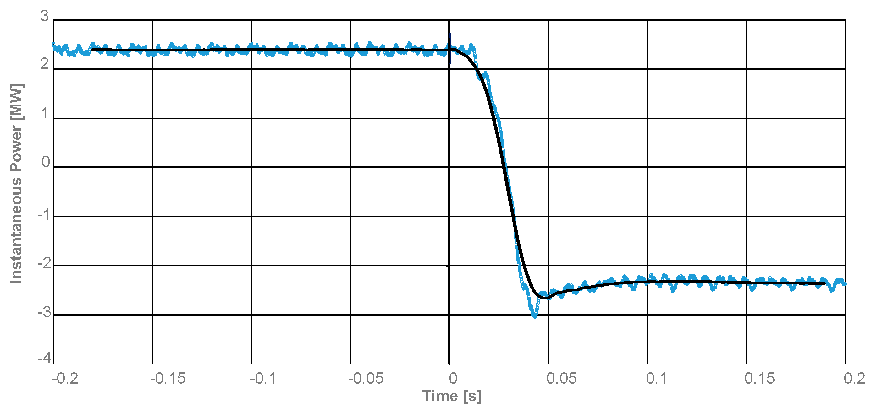
- Active power (P) modulation within 300 ms.
EESS rapidity of varying the active is also used for these additional commands:
- Instantaneous maximum P feeding into the grid;
- Instantaneous maximum P absorption from the grid;
- Instantaneous P exchange stop.
The extremely fast response recorded for active power modulation (less than 300 ms from the request to the full activation) leads to considering, when including EESS in system defense plan, the utilization of this command (maximum power feeding or maximum power absorption, depending on the desired direction) instead of switch opening, traditionally used also for pump storage. In this regard, in some operational conditions, the effectiveness of EESS as a defense plan is doubled.
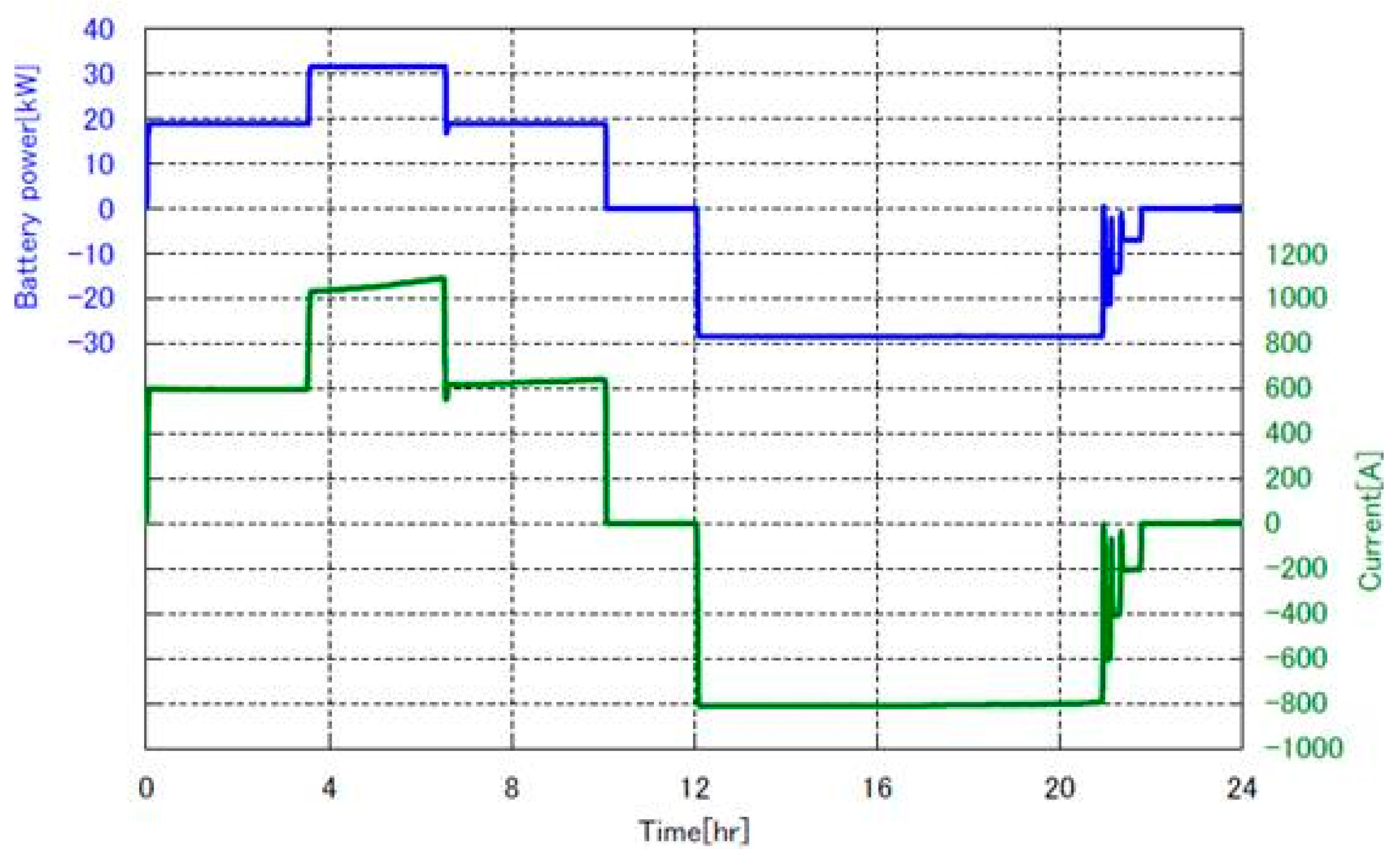
4. Some Returns on Operational Experience
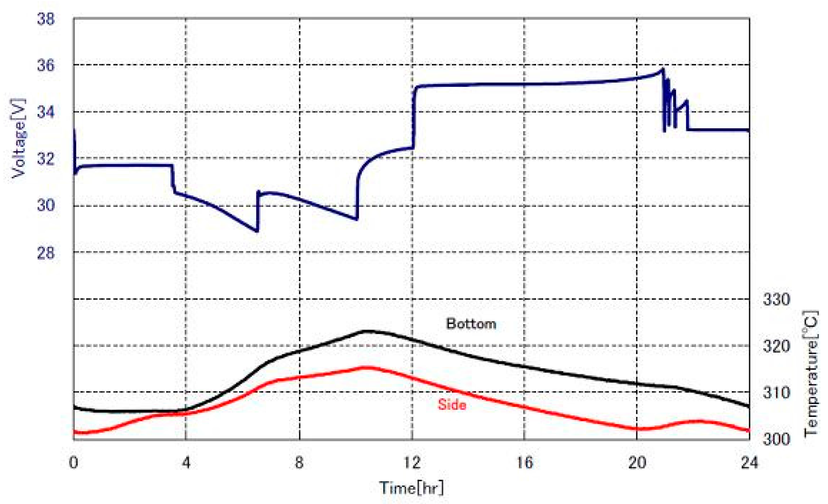
In order to have some measures on the real behaviour of the Italian energy intensive installations, Figure 8 shows the discharge/charge module power and current for a standard cycle. This involves:
- ➢
- a discharge phase of 10 h where for 7 h the discharge constant power is 0.6 p.u. and for 3 h the constant discharge power is 1 p.u.;
- ➢
- a charge phase of 10 h where a constant charge power of 1 p.u. for 8 h after which a supplementary charge (as already mentioned in Section 4) is needed in order to reach 100% of SoC.
Figure 8.
Current and DC power behaviour during a standard cycle in a module.
In Figure 9, the voltage and temperature inside a module are shown with reference to the standard cycle shown in Figure 8. With regard to the transient conditions, Figure 10 shows the inversion of the power flow from discharge to charge. It is worth noting that power inversion occurs in about 150 ms which is fully suitable for energy intensive stationary installations in the HV grid. The inversion from charge to discharge has a very similar behaviour.
Figure 9.
Voltage and temperature (at side and bottom of the module) during a standard cycle.
Figure 10.
Rated discharge to rated charge power: active one (dark line) and instantaneous one (azure line).
With reference to the Storage Lab installed in Sardinia, an operational data diagram focusing on FCR regulation triggered by the occurrence of a deep frequency transient is shown (see Figure 11). Table 5 and Table 6 report the technical datasheet of the EESS devoted to FCR regulation and its configuration, respectively.
Figure 11.
EESS GIG, total P output versus a real frequency transient (FCR contribution).
Table 5.
Technical datasheet of EESS devoted to FCR in Codrongianos (Sardinia).
Table 6.
FCR service configuration in the EESS of Table 5.
The frequency profile has experienced an initial under frequency phase, reaching the transient minimum value of 49.39 Hz, followed by an overshooting up to 50.17 Hz and consequent damped oscillations around 50 Hz.
Figure 11 clearly shows that the EESS can fully supply its rated power since the very beginning of the network transient, without noticeable delays. Furthermore, during the subsequent frequency variations, the EESS switches from discharge to charge according to the frequency error, contributing to oscillation damping. Notably, the actual EESS FCR behavior perfectly matches the expected one, confirming the efficacy of the control system.
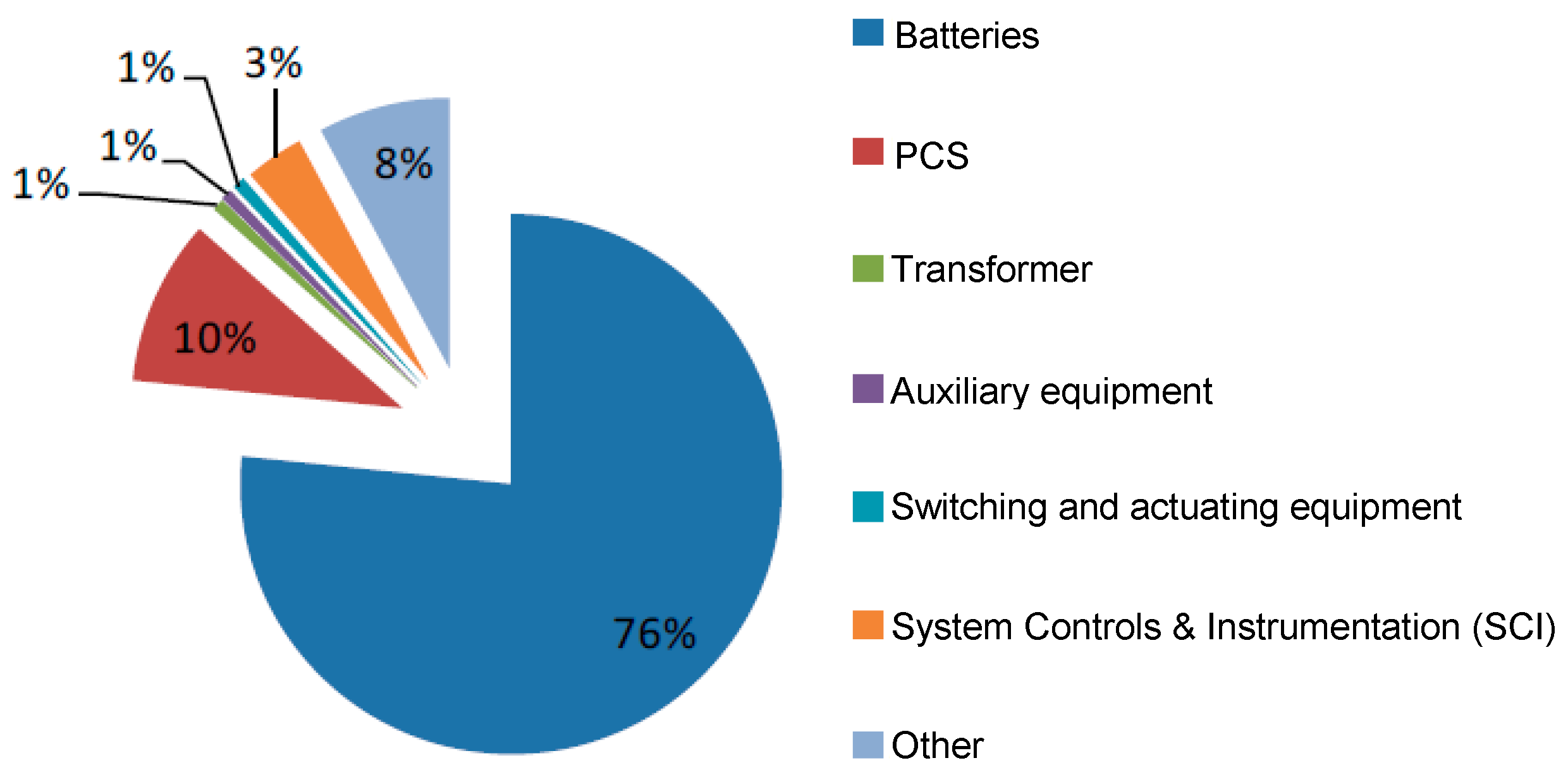
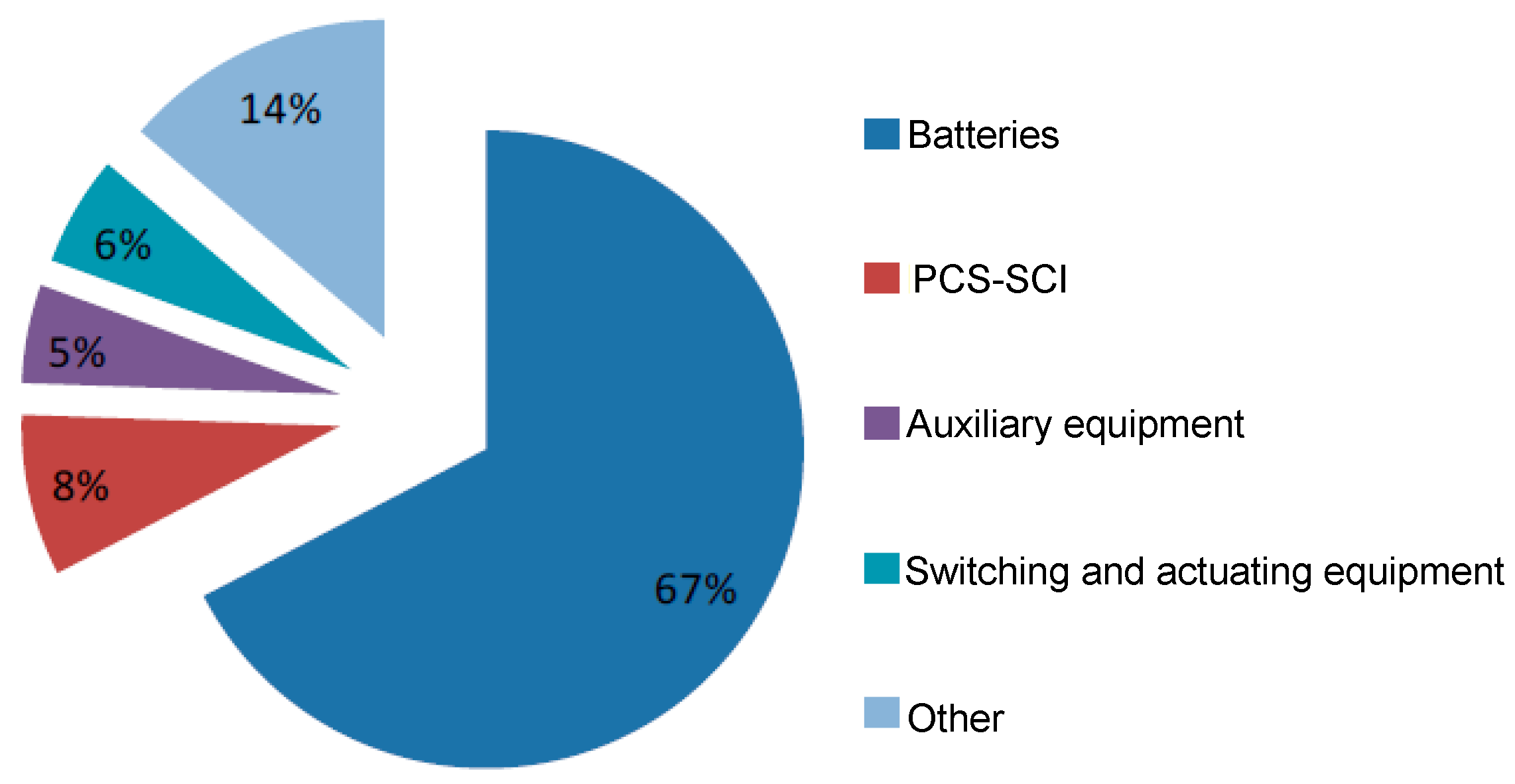
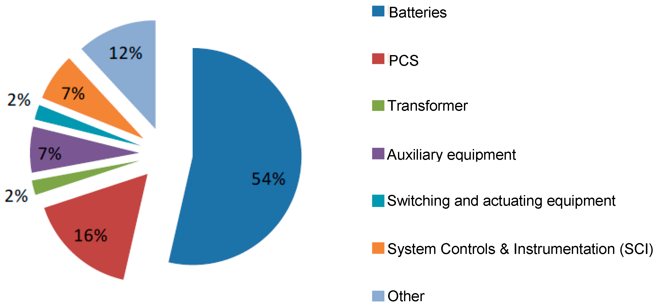
5. A Brief Cost Comparison
In order to have a comparison between the different cost components of the battery installations [27], Figure 12, Figure 13 and Figure 14 present the cost pie charts of Li-ion, Na-NiCl2, and Na-S respectively. The average total cost of Li-ion installations is 1.3 M€/MW and by considering an average discharge time for this technology equal to 1 h, the cost per MWh is 1.3 M€/MWh. The average total cost of Na-NiCl2 installations is 3.0 M€/MW and by considering the nominal discharge time for this technology equal to 3 h, the cost per MWh is 1.0 M€/MWh. The average total cost of Na-S installations is 3.3 M€/MW and by considering the nominal discharge time for this technology equal to 7.2 h, the cost per MWh is 0.46 M€/MWh.
Figure 12.
Li-ion percentage costs.
Figure 13.
Na-NiCl2 percentage costs.
Figure 14.
Na-S percentage costs.
The percentage ratio between PCS-SCI and battery costs is higher for Li-ion installations since the battery costs are lower.
6. Conclusions
This paper gives a wide overview of the energy storage projects installed in the Italian high voltage network. Safety issues, authorization procedures, and use applications of the energy and power intensive stationary electrochemical storage are throughout presented and developed. Li-ion (of different families), sodium-sulphur, sodium-nickel chloride electrochemistries have been tested with a total installed power of 50.75 MW.
In conclusion, it is possible to give some tendency lines: sodium-sulphur and sodium-nickel chloride with their long discharge times seem more suitable for energy intensive applications whereas Li-ion batteries seem more suitable for power intensive ones. Sodium-nickel chloride batteries show an attitude to be employed also in power intensive applications due to their intermediate discharge times.
Italian installations and their return on experience will play a key role in completely understanding the real battery behaviours in stationary applications including aging phenomena.
Author Contributions
Roberto Benato wrote the paper whereas the remaining co-authors collected the cost and installation data.
Conflicts of Interest
The authors declare no conflict of interest.
References
- Andriollo, M.; Benato, R.; Dambone Sessa, S.; Di Pietro, N.; Hirai, N.; Nakanishi, Y.; Senatore, E. Energy intensive electrochemical storage in Italy: 34.8 MW sodium–sulphur secondary cells. J. Energy Storage 2015, 5, 146–155. [Google Scholar] [CrossRef]
- Andriollo, M.; Benato, R.; Sessa, S.D. 34.8 MW di accumulo elettrochimico di tipo Energy Intensive mediante celle secondarie sodio-zolfo (Na-S). L’Energia Elettr. 2014, 5, 23–35. [Google Scholar]
- Andriollo, M.; Benato, R.; Sessa, S.D.; Di Pietro, N.; Polito, R. Large Scale Italian Energy Intensive Storage Installation: Safety Issues and Environmental Compatibility; Paper C4–115; Cigré: Paris, France, 2016. [Google Scholar]
- Sudworth, J.; Tilley, R. The Sodium/Sulfur Battery; Chapman and Hall: London, UK, 1985. [Google Scholar]
- Linden, D.; Reddy, T.B. Handbook of Batteries, 3rd ed.; McGraw-Hill: New York, NY, USA, 2002. [Google Scholar]
- Dustmann, C.-H.; Bito, A. Safety. In Encyclopedia of Electrochemical Power Sources; Garche, J., Dyer, C., Moseley, P., Ogumi, Z., Rand, D., Scrosati, B., Eds.; Elsevier: Amsterdam, The Netherlands, 2009; Volume 4, pp. 324–333. [Google Scholar]
- Ohima, T.; Kajita, M.; Okuno, A. Development of sodium-sulfur Batteries. Int. J. Appl. Ceram. Technol. 2004, 1, 269–276. [Google Scholar] [CrossRef]
- Wen, Z.; Cao, J.; Gu, Z.; Xu, X.; Zhang, F.; Lin, Z. Research on sodium sulfur battery for energy storage. Solid State Ion. 2008, 179, 1697–1701. [Google Scholar] [CrossRef]
- Xiaochuan, L.U.; Xia, G.G.; Lemmon, J.P.; Yang, Z.G. Advanced materials for sodium-beta alumina batteries: Status, challenges and perspectives. J. Power Sources 2010, 195, 2431–2442. [Google Scholar] [CrossRef]
- Iijima, Y.; Sakanaka, Y.; Kawakami, N.; Fukuhara, M.; Ogawa, K.; Bando, M.; Matsuda, T. Development and field experiences of NAS battery inverter for power stabilization of a 51 MW wind farm. In Proceedings of the 2010 International Power Electronics Conference (IPEC), Sapporo, Japan, 21–24 June 2010; pp. 1837–1841.
- Benato, R.; Cosciani, N.; Crugnola, G.; Sessa, S.D.; Lodi, G.; Parmeggiani, C.; Todeschini, M. Sodium Nickel Chloride battery technology for Large-scale Stationary Storage in the High Voltage Network. J. Power Sources 2015, 293, 127–136. [Google Scholar] [CrossRef]
- Benato, R.; Sessa, S.D.; Cosciani, N.; Lodi, G.; Parmeggiani, C.; Todeschini, M. La tecnologia sodio-cloruro di nichel (Na-NiCl2) per l’accumulo elettrochimico stazionario sulla rete di trasmissione. L’Energia Elettr. 2014, 4, 71–84. [Google Scholar]
- Sessa, S.D.; Crugnola, G.; Todeschini, M.; Zin, S.; Benato, R. Sodium nickel chloride battery steady-state regime model for stationary electrical energy storage. J. Energy Storage 2016, 6, 105–115. [Google Scholar] [CrossRef]
- Andriollo, M.; Benato, R.; Bressan, M.; Sessa, S.D.; Palone, F.; Polito, R.M. Review of Power Conversion and Conditioning Systems for Stationary Electrochemical Storage. Energies 2015, 8, 960–975. [Google Scholar] [CrossRef]
- Rebolini, M.; Tosi, S.; Vanadia, R.; Di Pietro, N.; Senatore, E.; Polito, R. The Authorization Procedure for Energy Storage Systems Projects Installed on the Italian Transmission Grid; Paper C3–103; Cigré: Paris, France, 2016. [Google Scholar]
- Gatta, F.M.; Geri, A.; Lauria, S.; Maccioni, M.; Codino, A.; Gemelli, G.; Palone, F.; Rebolini, M. Modelling of battery energy storage systems under faulted conditions: Assessment of protection systems behavior. In Proceedings of the 2016 IEEE 16th International Conference on Environment and Electrical Engineering (EEEIC), Florence, Italy, 6–8 June 2016.
- Gatta, F.M.; Geri, A.; Maccioni, M.; Lauria, S.; Palone, F. Arc-flash in large battery energy storage systems —Hazard calculation and mitigation. In Proceedings of the 2016 IEEE 16th International Conference on Environment and Electrical Engineering (EEEIC), Florence, Italy, 6–8 June 2016.
- Gatta, F.M.; Geri, A.; Lauria, S.; Maccioni, M.; and Palone, F. Battery Energy Storage Efficiency Calculation Including Auxiliary Losses: Technology Comparison and Operating Strategies. In Proceedings of the IEEE PowerTech Conference, Eindhoven, The Netherlands, 29 June–2 July 2015; pp. 1–6.
- Benato, R.; Sessa, S.D.; Crugnola, G.; Todeschini, M.; Zin, S. Sodium nickel chloride cell model for stationary electrical energy storage. In Proceedings of the 2015 AEIT International Annual Conference (AEIT), Naples, Italy, 14–16 October 2015; pp. 1–6.
- Benato, R.; Sessa, S.D.; Necci, A.; Palone, F. Sodium-Nickel chloride (NaNiCl2) Experimental Transient Modelling. In Proceedings of the 2016 AEIT International Annual Conference (AEIT), Capri, Italy, 5–7 October 2016; pp. 1–6.
- Benato, R.; Sessa, S.D.; Necci, A.; Palone, F. Sodium-nickel chloride battery experimental transient modelling for energy stationary storage. J. Energy Storage 2016. [Google Scholar] [CrossRef]
- Benato, R.; Sessa, S.D.; Crugnola, G.; Todeschini, M.; Turconi, A.; Zanon, N.; Zin, S. Sodium-Nickel chloride (Na-NiCl2) battery safety tests for stationary electrochemical energy storage. In Proceedings of the 2016 AEIT International Annual Conference (AEIT), Capri, Italy, 5–7 October 2016; pp. 1–6.
- Benato, R.; Sessa, S.D.; Crugnola, G.; Todeschini, M.; Turconi, A.; Zanon, N.; Zin, S. Test Di Sicurezza Su Batterie Sodio-Cloruro Di Nichel Per L’accumulo Elettrochimico Stazionario. L’Energia Elettr. 2015, 92, 47–53. [Google Scholar]
- Carlini, E.M.; Bruno, G.; Gionco, S.; Martarelli, C.; Ortoloano, L.; Petrini, M.; Zaretti, L.; Polito, R. Electrochemical Energy Storage Systems and Ancillary Services: The Italian TSO’s Experience; Paper C4–116; Cigré: Paris, France, 2016. [Google Scholar]
- TERNA Italian Grid Code. Annex 15: Participation in the Regulation of Frequency and Frequency/Power. Available online: www.terna.it (accessed on 1 December 2015).
- Xu, B.; Oudalov, A.; Poland, J.; Ulbig, A.; Andersson, G. BESS Control Strategies for Participating in Grid Frequency Regulation. IFAC Proc. Vol. 2014, 47, 4024–4029. [Google Scholar] [CrossRef]
- Tortora, A.C. Storage E Sicurezza Della Rete: I Progetti Di Terna. Available online: http://www.aeit-taa.org/Documenti/TERNA-2016-01-27-Storage-on-Grid-sicurezza-rete.pdf (accessed on 1 December 2016).
© 2017 by the authors; licensee MDPI, Basel, Switzerland. This article is an open access article distributed under the terms and conditions of the Creative Commons Attribution (CC-BY) license (http://creativecommons.org/licenses/by/4.0/).


