Next Article in Journal
17th European Conference on Eye Movements 11–16 August 2013, Lund, Sweden
Previous Article in Journal
Implicit Prosody and Contextual Bias in Silent Reading
 
 
Journal of Eye Movement Research is published by MDPI from Volume 18 Issue 1 (2025). Previous articles were published by another publisher in Open Access under a CC-BY (or CC-BY-NC-ND) licence, and they are hosted by MDPI on mdpi.com as a courtesy and upon agreement with Bern Open Publishing (BOP).
Article

Dynamic Programming for Re-Mapping Noisy Fixations in Translation Tasks

by
Michael Carl
Copenhagen Business School, 2000 Frederiksberg, Denmark
J. Eye Mov. Res. 2013, 6(2), 1-11; https://doi.org/10.16910/jemr.6.2.5
Published: 5 August 2013

Abstract

:
Eyetrackers which allow for free head movements are in many cases imprecise to the extent that reading patterns become heavily distorted. The poor usability and interpretability of these gaze patterns is corroborated by a “naïve” fixation-to-symbol mapping, which often wrongly maps the possibly drifted center of the observed fixation onto the symbol directly below it. In this paper I extend this naïve fixation-to-symbol mapping by introducing background knowledge about the translation task. In a first step, the sequence of fixation-to-symbol mappings is extended into a lattice of several possible fixated symbols, including those on the line above and below the naïve fixation mapping. In a second step a dynamic programming algorithm applies a number of heuristics to find the best path through the lattice, based on the probable distance in characters, in words and in pixels between successive fixations and the symbol locations, so as to smooth the gazing path according to the background gazing model. A qualitative and quantitative evaluation shows that the algorithm increases the accuracy of the re-mapped symbol sequence.

Introduction

Translation Process Research has advanced to a state where recordings of behavioural data are used to elicit and model cognitive processes in the translator’s mind. In particular, the relation between the rhythm and speed of typing activities and gazing behaviour is a valuable resource to understanding the translator’s black box. While the gazing behaviour reveals details about the text comprehension process, the typing of the translation shows us how the target text is produced and revised. In between these two activities lies the human translation process which we aim at understanding and modelling by looking at the physically measurable in- and output. The accuracy of the gaze data is crucial to obtain an undistorted approximation of these cognitive processes.
However, gaze data collected from eyetrackers is often noisy. The measured gaze location often does not exactly correspond to the spot that a subject actually looked at so that an analysis of the data may lead to misleading conclusions. This is harmful when studying gaze data during reading (or writing) activities where we are dealing with relatively small spacial areas - words or characters - on the screen. A horizontal displacement of a few characters is still tolerable as it may still map to the same, or at least a neighbouring word, while a vertical displacement of only one line corresponds to a jump of perhaps 10 words, which may imply completely misleading conclusions when analysing the data. A vertical drift thus contributes more noise and may falsify major parts of the findings.
Noise and drift in gaze data has been addressed in several ways. A frequent method is to assess the collected data after an experimental sessions and disregard data which is too noisy. However, this seems impractical in a setting which allows for free head movements, which potentially add noise in almost every recording. Other methods make use of re-calibration on the fly Juhasz et.al (2006), or by means of Required Fixation Location (Hornof and Halverson, 2002). In this latter method, participants are asked to place the mouse cursor over the objects they are looking at. The discrepancies between the mouse cursor and the recorded fixations are then measured revealing a drift or noise offset which may then be corrected.
Figure 1. Replay with naïve fixation-to-symbol mapping showing a translation segment of 8 seconds. Top: the Translog-II replay shows the gaze sample points (red and green), the fixations and fixation to word mapping. Bottom: the translation progression graph shows the same segment of time with fixations on the source text (blue) fixations on the target text (green) and keystrokes.
Jemr 06 00010 g001
Such methods are also undesirable as they distract translators, readers or writers form their usual way of working. Other solutions are necessary, in order to allow as much as possible for an ecologically valid working environment.
Mishra et al (2012) propose an heuristics-based technique to reduce constant deviations between users’ intended gaze location and the location captured by eye-samplers, so-called systematic errors. These error-correcting heuristics are intended to shift gaze fixations to their “true locations”, under the assumption that the measured gaze data at the beginning of a new line is often correct, while the effects of gaze drift worsen as the eyes move towards the end of the line. Accordingly, the method of Mishra et al. places most importance on the first few fixations on each line, and successive fixations are subsequently mapped onto this line. A similar method has been described by Špakov (2007), with, however, a less sophisticated mechanism to determine the reading line from the first observed fixations.
In this paper I describe a fixation re-mapping algorithm that is tailored especially to translation activities. In translation, the eyes move frequently between two texts, the source text and its translation, which calls for specific solutions, but which also gives us more clues as to which symbols and words the translator may be reading. In the first section I discuss drifting problems in a sequence of recorded translation activity data, and why these drifting problems are difficult to capture with existing methods. From the description of the drifting problem I then elaborate criteria for enhanced fixation-to-symbol mapping in translation tasks. The following section describes the implementation of the fixation re-mapping algorithm and a final section discusses evaluation issues.

The Problem

In contrast to typical monolingual reading, a translator deals with two texts, a source text and its translation. While the source text (ST) is usually static, the target text (TT) translation dynamically evolves over time as a result of the translation process. During translation production, the translator’s gaze often switches between the ST and the TT, with short sequences of reading in the ST window and monitoring of text production in the TT window. The reading activities are characterized by short ST and TT reading patterns, frequent regressions and re-fixations, and long saccades between the two texts, which lead to scattered fixations when moving from one text to the other, incorrect landing sites, and increased gaze measuring and mapping errors.
Figure 1 (top) shows an 8 second long fragment of a translation session from an English text into Estonian. In these 8 seconds the characters ”[pöllu]majandus ja sellest tulene” were typed (context is added in square brackets) which - according to my back-translation from Estonian using google - corresponds to a translation of ”agriculture and its pressure” in the English text.
The data was collected using Translog-II (Carl, 2012) and a Tobii T120 eyetracker, running in the 60Hz mode. The figure has three different types of gaze information: red and green dots represent gaze samples collected from the left and right eyes respectively. Blue circles represent fixations (i.e. clusters of coherent gaze points) for which the numbers on the fixations reflect their temporal ordering, so that fixation 0 occurred first, followed by fixation 2, then 3 etc. The third type of information is fixation-to-symbol mappings indicated by the violet background behind sequences of characters. Figure 1 shows a naïve fixation-to-symbol mapping. That is, the center of the fixations are mapped to the closest character and the background of the surrounding 6 characters are coloured in violet. These characters and words are then supposed to represent the words that were looked at by the translator and are the basis of further analysis of reading behaviour.
A number of issues may distort this fixation-to-symbol mapping process, including:
  • due to calibration difficulties, free head movement or changes in light or other conditions, the gaze sample points which are recorded may not exactly correspond to the place which was gazed at.
  • the choices that are made when computing the fixation, e.g. based on the left or the right eye gaze sample, their average, how proximity or saccades between successive gaze samples are defined, etc.
  • the computation of the closest character for a given x/y position depends on which part of the character is taken as a reference, e.g. the upper left corner, or the center of the character, etc.
In Figure 1 (top), the fixations (blue circles) were computed based on the average of the left and the right eye sample, with the assumption that fixations should be at least 40ms in duration, and that all gaze samples within a fixation are no more than 25 pixels from the fixation center. In Figure 1 (top) most of the gaze samples lie between the first and the second line, but the fixation centers are mostly mapped onto the words in the second line.
However, it is likely that the translator actually read a segment in the first line, since s/he is currently producing the translation of ”agriculture and its pressure” while the gaze moves back and forth between the source segment in the upper window and its translation in the lower window.
Figure 1 (bottom) shows the same segment in the form of a translation progression graph. The horizontal axis represents 8 seconds in which the fragment of the translation was typed (70.000ms to 78.000ms) while the vertical axis presents the source text to which the translation activities relate. The graph plots how the characters were typed in time: black characters are insertions and red characters deletions. The graph shows that there are several stretches of fluent writing (e.g. “jandus” and “ja”) and several pauses of different length (e.g. there is a pause of almost 1 sec between the typing of “jandus” and “ja”). Blue dots represent fixations on the source text words in the upper part of the Translog-II window while the green diamonds represent fixations on the translations in the lower window. Note that the blue dots in the bottom part in Figure 1 and Figure 2 correspond to the violet fixation-to-symbol mappings in the top part of the figure.
The segment shows that the translator was typing “ma” while the gaze was on the target window. The gaze moved then to the source window (blue dots), while typing “jandus ja” and then came back to the target, inspecting the just typed words (green diamonds), and then keeps on typing in “sellest tulene”, while correcting a few typos (characters in red).
Figure 1 shows the drift of gaze data and wrong fixation-to-symbol mapping in the source window: while the translation of source words 3 to 5 were typed, fixations in the source text are around words 17 to 26. However, it is likely that a translator read approximately the same words that s/he is currently translating, and not 12 or 20 words ahead.
Figure 2 shows the output of the automatically re-mapped version. The fixation-to-symbol mapping has been changed so that the mappings occur in the first line in the source window. The location of the keystrokes, as well as the gaze samples and the computation of the fixation centers are identical in the two pairs of figures, only the fixation-to-symbol mapping has changed in Figure 2. Figure 2 (bottom) shows the progression graph of the re-mapped segment, so that the distances between successive fixations become smoothed.
Figure 2. Replay with re-computed fixation-to-symbol mapping showing the 8 second translation segment from Figure 1. Top: the Translog-II replay shows the gaze sample points (red and green), the fixations and fixation to word mapping a line above the mappings in Figure 1. Bottom: the translation progression graph shows the same segment of time with fixations on the source text (blue) fixations on the target text (green) and keystrokes.
Jemr 06 00010 g002
Even though we cannot be sure what a translator actually looked at – e.g. whether s/he read a segment in the first or second line - intuitively it seems more plausible that a translator reads source words which he or she is currently translating (as in Figure 2) instead of those words one line below (as in Figure 1). These observations lead us to the following criteria for a fixation-to-symbol re-mapping algorithm:
-
successive fixations are more likely on neighbouring words than in the lines above or below
-
translators are likely to read passages of source text words which they are currently translating
-
the distance between the fixation center and the fixated characters should be minimal

A Fixation Re-mapping Algorithm

The proposed fixation re-mapping algorithm consists of 3 steps:
1.
re-compute fixation from gaze samples and compute naïve fixation-to-symbol mapping
2.
extend naïve mapping into a lattice of possibly looked-at symbols
3.
find the best path through the symbol lattice, depending on whether previous successive fixation:
  • occurs in the same window
  • involves a change of window
  • shows systematic drift
This section describes these three steps in more detail, and an evaluation of the algorithm is discussed in the next section.

Fixation Re-computation

Before applying the actual fixation re-mapping algorithm, fixations must be re-computed in a consistent manner with the following parameters:
-
the minimum fixation duration is set to 40 ms
-
each gaze-sample point must occur within 25 pixels from the center of the fixation
-
a gap in gaze-sample data of more than 30ms will trigger a fixation boundary
The nearest character to the median gaze sample within a fixation would then be taken as the fixation-to-symbol mapping. Figure 1, Figure 4 (top) and Figure 5a show the results of this naïve fixation-to-symbol mapping, which results in numerous erroneous symbol mappings a line below the one that the translator actually translated. The naïve mapping was subsequently re-mapped based on the following algorithm.
Figure 3. Figure 3a to 3d from top left to bottom right: Figure 3a shows the projection of the naïve mapping into a lattice of alternative fixation-to-symbol re-mappings (red dots). Figure 3b (top, right) plots links to the first successor node, figure 3c (bottom, left) and 3d (bottom, right) show successive steps in the re-mapping algorithm, including links to pre-predecessor nodes.
Jemr 06 00010 g003

Symbol lattice expansion

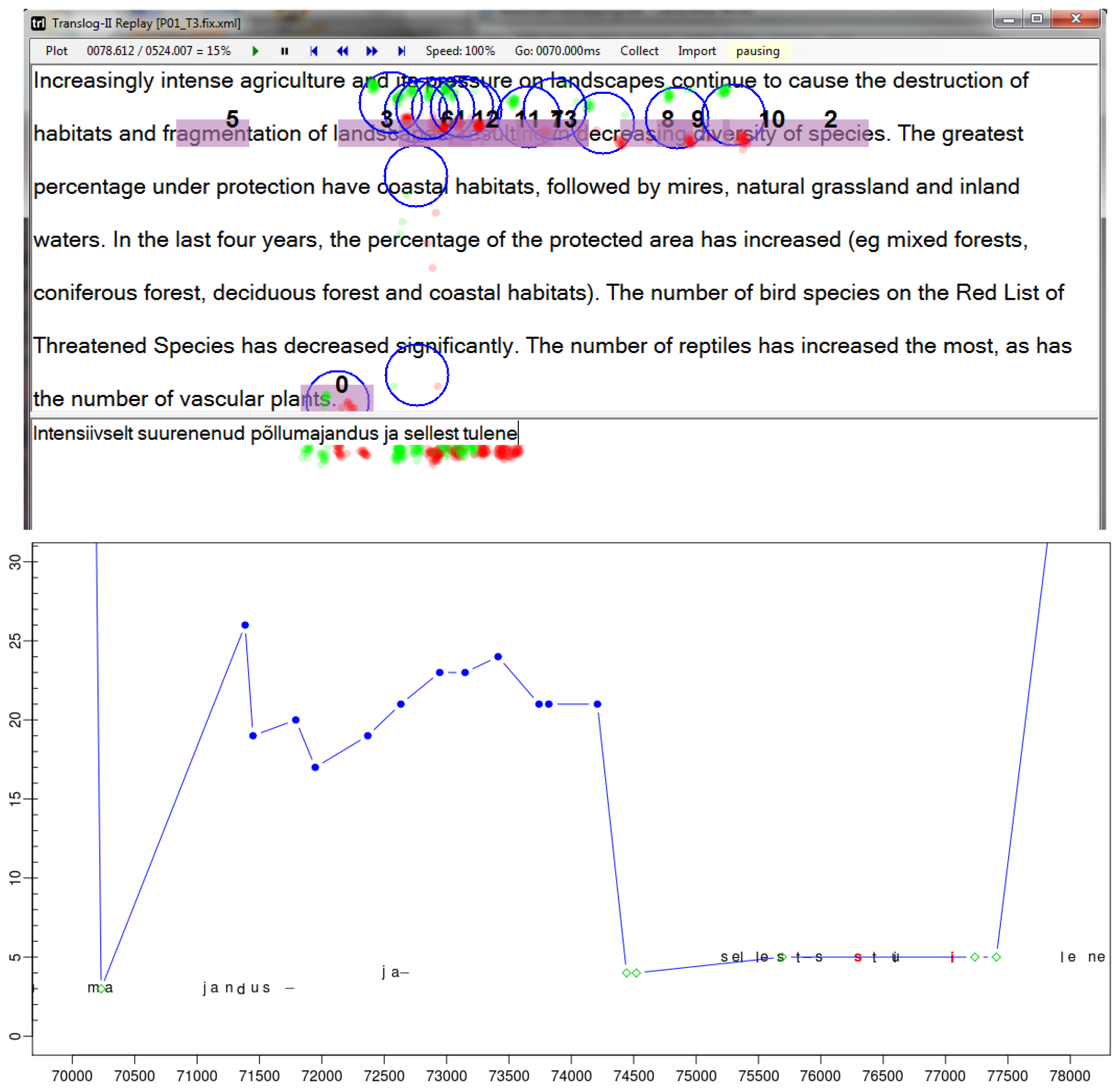
In the second step, the sequence of "naïve" fixation-to-symbol mappings (as in Figure 1) is projected into a lattice of several possible correct symbol locations above and below the current fixation on the text. Then a dynamic programming algorithm applies a number of heuristics to find the best path through the lattice, based on the distance in characters, in words and in pixels between successive fixations, so as to smooth the gazing path according to observations reported in the literature.
Figures 3a to 3d illustrate this process based on the sequence of fixations and keystrokes between time stamps 70.000 and 73.000 in Figure 1 and Figure 2. It illustrates the re-mapping of the fixation path in figure 1 (bottom) to the path plotted in figure 2 (bottom). Additional fixations are computed from the gaze sample points, in the following way:
-
compute the fixation center only from the left eye gaze samples
-
compute the fixation center only from the right eye gaze samples
-
compute the fixation center from the average of the left and the right eye gaze samples
The fixation centers are then mapped onto the closest nearby character in the source or target window, a so-called fixation-to-symbol mapping. There are thus three different fixation-to-symbol mappings average, left and right, depending on which fixation they are based on. In addition, a character is retrieved in the line above the uppermost fixation-to-symbol mapping (up), and a character is retrieved in the line below the lowest fixation-to-symbol mapping (down). In this way, five fixation-to-symbol mappings are generated in addition to the original one, which may, however, partially overlap with these additional mappings.
While Figure 1 (bottom) shows the naïve average fixation, 
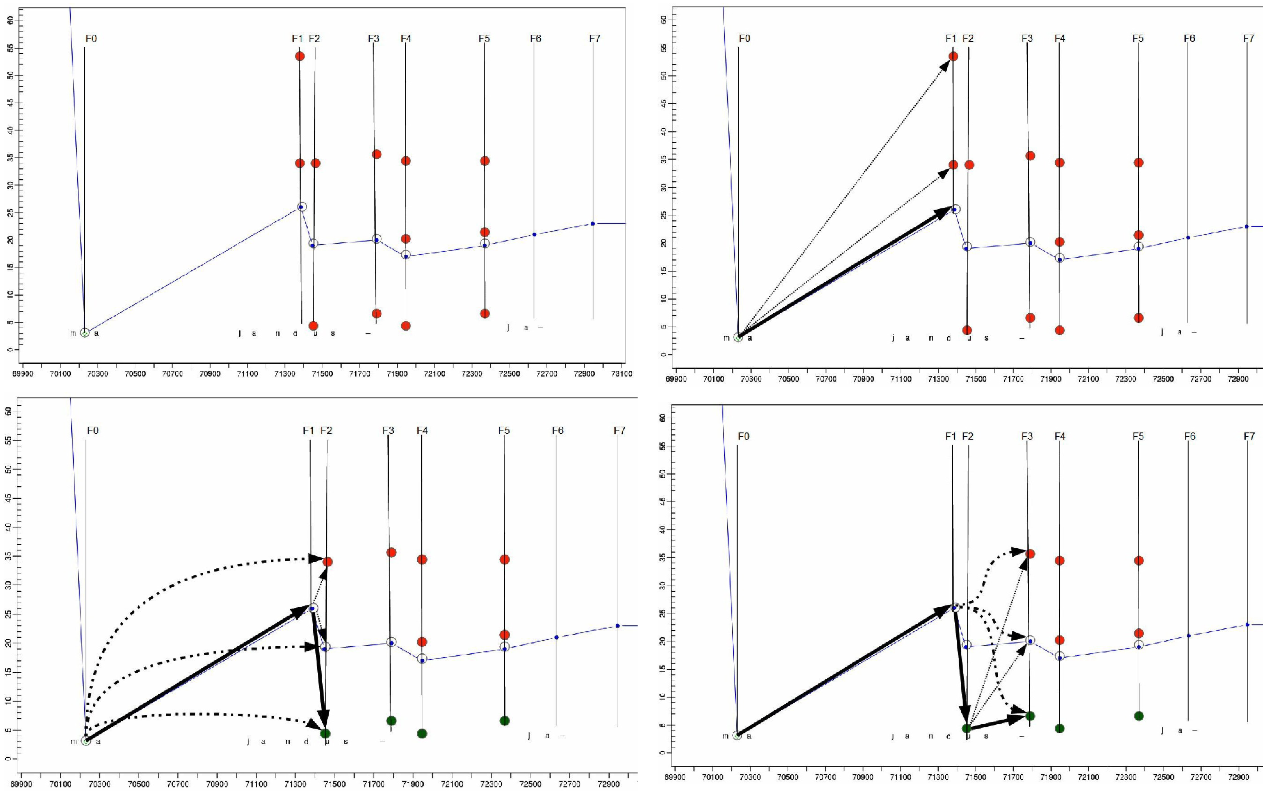
figure 3a shows the same situation, where the original naïve fixation-to-symbol mapping path is plotted (in blue) and additionally re-computed fixation-to-symbol mappings are represented as dots on the vertical fixation time line Ft. Figure 3a shows the projection of fixations on the lines above and below the naïve default mapping. For fixation time F1, two additional fixation-to-symbol mappings are generated in the lines below the naïve mapping (in the progression graphs the words further down in the text appear higher in the graph), while for fixations times F2 and F3 fixation-to-symbol mappings are generated in the lines above and below the default naïve mapping. Note that different fixation-to-symbol mappings at one fixation time may also be distributed in different windows. For instance, a 
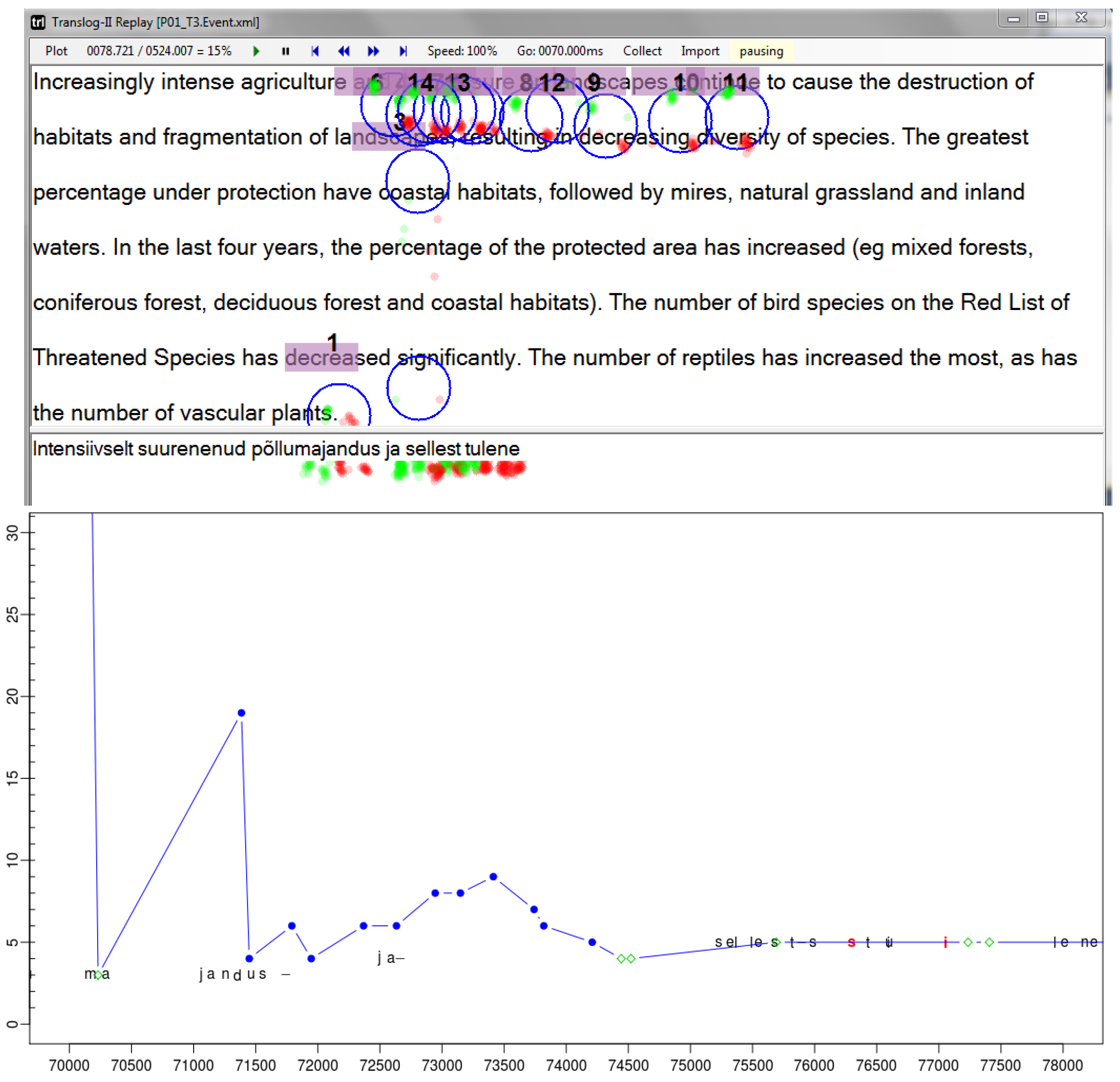
down re-mapping of the fixation numbered 0 in Figure 1 (top) at the bottom of the source window may be re-located in the top of the target window, while the up alternative would appear in the source window, e.g. on decreased, as shown in figure 2 (top), where the same fixation is numbered 1.

Symbol lattice smoothing: same window

In the third step a path through the lattice of possible fixation-to-symbol mappings is re-computed based on the minimum penalty score of the distances between successive nodes. Assuming that a fixation-to-symbol mapping n is consolidated for a given fixation time Ft, a penalty score for each possible fixation-to-symbol mapping m at the next fixation time Ft+1 and its fixation center f is computed by summing up a number of features as described below. The fixation-to-symbol mapping m with the lowest penalty score is then consolidated. Figure 3b shows the links to the three possible successor nodes, where the link in bold represents the strongest connection with lowest penalty score. We use two variants of the algorithm, one in case both fixations are recorded in the same window, and another method, described below, if n and m are in different windows.
Different features are considered when computing the penalty scores between successive nodes, depending on whether the two successive fixation mappings occur in the same window, or whether the gaze moves from the source window to the target window or vice versa. In case two successive fixations occur in the same window (i.e. the source or target window), we assume that a sequence of text is being read so that the eyes probably move forward over the text. In case the eyes move from one window to the other, we assume that the eyes move (close) to the translation of the sequence that was previously looked at in the other window. In this subsection we formalize the former case of text reading in one window and the next section tackles the case of window switching.
According to (Rayner, 1998), during “normal” reading the eyes can jump distances of around 5 to 15 characters along the text from left to the right, often skipping short function words. As drift of gaze data is presumably quite rare, we suspect that the gaze sample points which are received from the eye tracker, and thus the center of the various fixations that we compute from them, are close to the characters and words which are actually read. In addition, we assume that translators read a piece of text (in the source or the target window) which is close to the sequence currently being translated. These considerations are formalized in the following four functions:
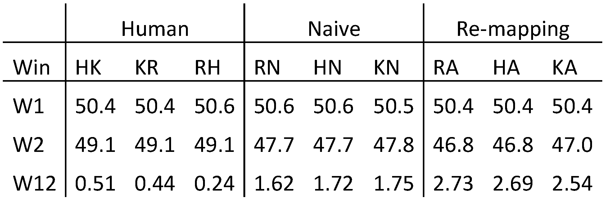
 Jemr 06 00010 i001
where n and m represent two fixation-to-symbol mappings, f is the fixation center of m, K=6 is approximately the average length in characters of (English) words, z=24 is the size of the characters on the screen that we used in these experiments, and l is the cursor position of the last character that was typed in the target window.
The Source Text word Id STID(.) is computed based on the alignment between the source and target text. Words in the source and target target text are numbered, and the alignment information allows us to know the Source Text word Id for each target word in the translation. This information can be linked to the keystrokes which actually produce the target words and the target text. An algorithm described in (Carl, 2013) describes how Source Text word IDs for keystrokes and fixations are computed from the alignments.
Between each consolidated fixation-to-symbol mapping n at time Ft and every possible successor node m at the following fixation time Ft+1, a penalty score is computed as shown in equation (5): Jemr 06 00010 i002
Since sometimes the eye may slip up or down a line or two (particularly when switching between the two windows) we also compute the penalty score between the consolidated node o at the preceding fixation time Ft-1 and the successor mapping m, so as to lessen the impact of the current mapping potentially being a slipped fixation on the gaze path, as shown in equation (6) : Jemr 06 00010 i003
This situation is depicted in figure 3c. There is one consolidated node n at fixation time F1 which is connected to all three possible successor nodes m1..3 at fixation time F2. These connections are represented by fine dotted lines. In addition, there are connections from the consolidated node o at fixation time F0 which link to the three possible fixation-to-symbol mappings in F2. These links are represented by dashed curved connectors. There are thus six penalty scores for the three nodes m1..3 in F2. The node with the lowest penalty is consolidated. The link to the previous consolidated fixation mapping in F1 is plotted in bold arrows in Figure 3c. Even though the distance to its immediate predecessor node in F1 is quite large, the bottom node m in F2 was consolidated due to the similar Source Text word Id which it shares with the consolidated fixation-mapping node in F0 and its proximity to the previously typed character. The algorithm iterates through the expanded fixation-to-symbol mapping lattice. Once a fixation-to-symbol mapping is consolidated, the penalties of the next fixation nodes are computed as shown in Figure 3c and so on until the end of the lattice is reached.

Symbol lattice smoothing: different window

As mentioned previously, penalty scores are computed slightly differently if the two successive fixation-to-symbol mappings are distributed in different windows. Since shifting attention from one window to another window (i.e. switching between two texts) is different from usual reading behaviour, we do not assume that eyes move in jumps of around 10 characters, and omit the cursor distance penalty function C(.). Rather, the eyes seek to retrieve the translation of the word that was looked at (or worked on) in the other window, and thus the value STID(n) of one fixation will be similar to STID(m) of the following fixation. That is, penalty scores increase as the two successive fixations-to-word mappings return a different STID(.) in both windows: Jemr 06 00010 i004
The last keystroke distance L(.) and the Fixation-symbol distance 
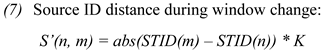
P(.) as in equation (3) and (4) remain the same also when changing windows. For sequences of fixations which imply window changes, we thus introduce two functions, analogous to the case in which the eyes stay in the same window, in which S’LP1(n, m, f) computes the penalty scores for immediate successive nodes and S’LP2(o, m, f) computes the penalty scores for two nodes distance: Jemr 06 00010 i005

Systematic error correction

The brain usually prefers visual input from one eye which is referred to as the dominant eye. Accordingly, fixations computed with the gaze data of the dominant eye correspond more precisely to the visual input and hence reveal more accurately what the brain was actually processing. According to wikipedia (http://en.wikipedia.org/wiki/Ocular_dominance), approximately two-thirds of the population is right-eye dominant and one-third left-eye dominant. As outlined above, we compute left, right and average fixation-to-symbol re-mappings. Since we do not know the eye dominance of our participants, the left and the right fixation-to-symbol mappings take into account the fact that the preferred visual input may be on the left or right eye respectively, while the average takes the average over both eyes. We can expect that the left, right, or average mappings do not change from one fixation to the next: the dominant eye does not change from one fixation to another.
In addition, we frequently observe instances of gaze drift, where the observed gaze data is a line below or above the one that we think it is plausible to assume the person was actually reading. The up and down fixation-to-symbol re-mappings take into account such systematic gaze drifts by simulating a shifting of the observed fixation a line up or down. Since gaze data does not usually drift within short periods of time from the line above to the line below, we assume that the left, right, average, up and down fixation re-mappings are stable over stretches of time. To take this constraint into account, the fixation-symbol distance penalty P(f,m) from equation (4) is relaxed if two successive fixations mappings have the same re-mapping values, as in equation (10): Jemr 06 00010 i006
where ReMap(x) returns one of the values up, down, left, right or average, according to the way in which the fixation-to-symbol mapping was computed.

Evaluation

This section describes a quantitative and a qualitative evaluation of the re-mapping algorithm. We generated a set of gold standard data by manually mapping fixations onto their “correct” symbols, against which the algorithm can be tested. The second evaluation looks at an example and relates the resulting re-mapping to a model of translation.

Quantitative Assessment

One way to assess the quality of an automatically generated fixation-to-symbol re-mapping is to compare it against manually adjusted gold standard data. Given that the Translog-II replay mode allows us to observe text production together with gaze behavior (examples of screen shots are given in Figure 1 and Figure 2), it is possible, but a laborious task, to manually re-map fixations onto the more plausible words and characters in the text. For this purpose, Translog-II has a “remap” mode in which it stops at each fixation. A user can position the cursor over a character, and hit the return key and then Translog-II assigns the cursor position to the current fixation as its fixation-to-symbol mapping. The re-mapped file can then be stored and compared with other re-mapped versions.
To assess the accuracy and difficulty of this re-mapping task, three native Hindi speakers manually re-mapped the fixations of one Translog-II English -> Hindi translation session onto the words that they believed the translator looked at during the translation. They were instructed to select the most likely position that they thought the translator had looked at.
We compared these three re-mapped versions to each other. In addition, we compared each of the human fixation-to-symbol mapping to the baseline naïve and to the automatically generated mapping. This resulted in 9 comparisons of 3 human reference versions and 2 test files. All 9 comparisons agree that approximately 50.5% of all fixations occurred in the source window, while there is agreement that between 46.8% and 49.1% of the fixations should be located in the target window. For the remaining 0.51% to 2.73% of the fixations the reference and test versions do not agree as to whether the fixation was in the source window or in the target window. Table 1 shows the agreement of the distribution between two versions. “R”, “K” and “H” were three human annotators, “N” the naïve baseline mapping and “A” the automatic re-mapping introduced in this paper. Accordingly, the columns “HK”, “KR” and “RH” show the values of a comparison between the manually generated re-mapped versions of the three human translators. Compared to the naïve and automatically re-mapped version, the human annotators seem to largely agree on whether a fixation took place in the source or in the target window. They only disagree in between 0.24% to 0.51% of the fixations. The automatic method is most often incorrect and does not agree in 2.54% - 2.73% of the cases with the human generated gold standard data.
To assess the precision of fixation-to-symbol mapping, we computed the average normalized distance between the mapped character offset position in the reference file (cr) and the test file (ct). The offset distance was normalized by the fixation duration dur, which is identical in both files: Jemr 06 00010 i007
The Average Character Distance ACD reflects the distance between the fixation-to-symbol mappings of two files from a textual viewpoint: a fixation which is mapped onto a character in the line above or below the reference fixation results in a large penalty equal to the number of characters in that line, while a horizontal mismatch has a comparatively small penalty. Thus, even though the physical distance between two fixation mismatches may be identical, a vertical mismatch is considered much worse than a horizontal one.
Table 2 shows the ACD values for the 9 comparisons between the three manually generated reference mappings, the naïve mapping and the re-mapped version. The average ACD value for the three reference files varies between 8.6 and 12.6 for the reference file comparison, and between 34 and 37.7 for the machine generated fixation-to-symbol mappings. Inter-human annotation agreement is thus much higher compared to the naïve and re-mapped versions.
When looking into the distribution of the ACD error, a big difference can be observed for the source window (W1), and the target window (W2). The human annotators agree on the fixation mapping with approximately 1 word precision (3.5 – 8.5 characters) in the target window and approximately 2 words precision (8.7 – 13.9 characters) in the source window. In cases when a reference and a test file assigned the same fixation to a different window, the ACD value is particularly high. An example of this situation is shown in Figure 4, in which the same fixations have been mapped onto the last words in the source text (Figure 4, top) and in in another version on the first words in the target text (Figure 4, bottom). As the character offset in the first (source) text is high and in the second (target) text low, ACD has a particularly high value. Table 1 shows us that this is often the case in the case of re-mapping, which worsens the average ACD score.
Figure 4. different fixation-to-symbol mappings of two mapping approaches between time stamps 5000 and 10000. Top:fixation-to-word mappings on the last words in the source text (blue dots); Bottom: mappings on the first word in the target text (green diamonds).
Jemr 06 00010 g004
Figure 5. Figure 5a (top) naïve mapping vs. its re-mapped version 4b (bottom). Both figures represent the same translation segment.
Jemr 06 00010 g005
However, for fixations which are correctly detected in the source window (W1) or in the target window (W2) the ACS scores clearly outperform the naïve mapping.

Qualitative Assessment

A number of cognitive models of the human translation process exist which provide us with insights about the observed translation process data and which may serve as a basis for an evaluation of re-computed fixation-to-symbol alignment patterns. For instance, Jakobsen (2011) has found indications of a recurrent “micro-cycle”, i.e. a processing pattern consisting of six steps, some of which can be skipped or repeated several times. The processing cycle starts with an act of comprehension, namely reading the chunk of ST which is about to be translated (step 1). The translator then shifts his/her gaze to the TT to locate the position where the TT is about to be produced (step 2). The translation is typed and monitored (steps 3 and 4), and the translator’s gaze shifts back to the ST, where the relevant reading area is located and the current ST word is read again (steps 5 and 6) (Jakobsen 2011, 48).
While such models give us a general picture of what we may expect in the translation activity data, they are still far from exactly predicting where the next fixation is to be expected. In addition, a large variation of individual translation styles has been described, for instance in (Dragsted & Carl 2013), so that the evaluation of the re-mapped log files remains, for the moment, subjective and intuitive. In the future we hope that in a real-time reactive application the success of a re-mapping method could be evaluated based on its usefulness, Figure 5 show an example of the present re-mapping algorithm.
The progression graph in Figure 5a clearly shows a systematic drift of the source text fixation mappings about 12 to 20 words ahead of the translations on which the translator is working. Figure 4b shows a re-mapping which clearly comes closer to the initial main criteria which were previously established to design of the re-mapping algorithm:
-
successive fixations are one or two words apart
-
translators are likely to read source passages which they are currently translating
The re-mapped version also better accounts for the recurrent micro-cycle, as described above (Jakobsen 2011).

Acknowledgments

This work was partially supported by the CASMACAT project funded by the European Commission (7th Framework Programme).We are grateful to all contributors to the database for allowing us the use of their data. Particular thanks goes to Nancy Underwood for throughly re-reading of the manuscript.

References

  1. Dragsted, B., and M. Carl. 2013. Towards a classification of translation styles based on eye-tracking and keylogging data. Journal of Writing Research 5, 1: 133–158. [Google Scholar]
  2. Hornof, A. J., and T. Halverson. 2002. Cleaning up systematic error in eye-tracking data by using required fixation locations. Behavior Research Methods, Instruments, & Computers 34: 592–604. [Google Scholar]
  3. Jakobsen, A. L. 2011. Edited by C. Alvstad, A. Hild and E. Tiselius. Tracking translators’ keystrokes and eye movements with Translog. In Methods and Strategies of Process Research. John Benjamins: Amsterdam: pp. 37–55. [Google Scholar]
  4. Mishra, A., M. Carl, and P. Bhattacharya. 2012. A heuristic-based approach for systematic error correction of gaze data for reading. Workshop on Eye-tracking and Natural Language Processing, Coling 2012, 24th International Conference on Computational Linguistics, Mumbai, India; December 15. [Google Scholar]
  5. Rayner, K. 1998. Eye movements in reading and information processing: 20 years of research. Psychological Bulletin 124, 3: 372–422. [Google Scholar] [PubMed]
  6. Špakov, O. 2007. GWM–the Gaze-to-Word Mapping Tool. Available online: http://www.cs.uta.fi/~oleg/gwm.html.
Table 1. Percentage of agreement between two versions of fixation-to-symbol mappings in source and target window.
Jemr 06 00010 i008
Table 2. Average character distance between two fixation-to-symbol mappings for source window (W1) target window (W2),in case the fixations are mapped in different windows (W12) and the average character distance (AVG).
Jemr 06 00010 i009

