Abstract
Natural outdoor conditions pose unique obstacles for researchers, above and beyond those inherent to all mobile eye-tracking research. During analyses of a large set of eye-tracking data collected on geologists examining outdoor scenes, we have found that the nature of calibration, pupil identification, fixation detection, and gaze analysis all require procedures different from those typically used for indoor studies. Here, we discuss each of these challenges and present solutions, which together define a general method useful for investigations relying on outdoor eye-tracking data. We also discuss recommendations for improving the tools that are available, to further increase the accuracy and utility of outdoor eyetracking data.
Introduction
Early eye-tracking experiments required participants to stabilize their heads while looking at two-dimensional stimuli in a room with carefully controlled lighting. Many of the field’s standards for collecting and processing data reflect this history of stationary, laboratory-based eyetracking. Over the last two decades, the cost and quality of wearable eye-tracking systems has improved dramatically, allowing researchers to examine tasks that are performed away from a computer and even outside of the laboratory (for reviews, see Hayhoe & Ballard, 2005; Land, 2006; Land & Tatler, 2009). As head-mounted mobile eye-tracking has become more common, new recommendations for research with wearable trackers have emerged (e.g., chapters 5–8 of Duchowski, 2003; head-mounted tracking sections in Holmqvist et al., 2011). Despite the growing interest in mobile eyetracking, our recent work with outdoor scenes has revealed a need to revise methods for calibrating eye and scene videos, detecting ocular features, parsing the eye movement record into fixations, and comparing eye movements across subjects and time. Throughout this paper, we discuss the challenges that arise with mobile eye-tracking (and with outdoor data collection in particular) and present the solutions we have developed. Together, these provide a method for collecting and analyzing eye-tracking data from outdoor environments.
Many of these solutions were created for a study that monitors the eye movements of novice and expert geologists as they attempt to infer the geodynamic history of landscapes. In this multi-year project, eye movement data are collected during an annual class fieldtrip in which undergraduates from the University of Rochester visit numerous sites in central California and Nevada. Each year, we simultaneously record data from 11–13 observers. The observers are free to move around the outdoor environment as their eye movements are monitored. Because we track in remote areas, each recording session starts with setting up the eye-trackers at our ‘mobile lab’ (vans that store, power, and transport the eye-trackers between recording sessions). Once the observers are equipped and have calibrated the eye-trackers, they walk to an area from which they can view geologically significant features, and the class professor asks the group to visually inspect the scene for evidence of geological activity. It is during this period of active and goal-directed visual search that we have been focusing our analyses. After about 90 seconds of silent viewing, the students discuss the features they noticed, and the professor gives a lecture on the scene. They then walk back to the vans where the eye-trackers are removed and the group then drives to the next destination.
This work builds on decades of research examining the eye movements of experts (e.g., Charness, Reingold, Pomplun, & Stampe, 2001; Krupinski et al., 2006; Nodine & Kundel, 1987), but it is novel in the number of observers, the amount of data we are collecting, and the difficult, natural conditions in which we are recording. The demands of these new recording conditions revealed a need to revise the standard eye-tracking procedures, as discussed throughout this paper.
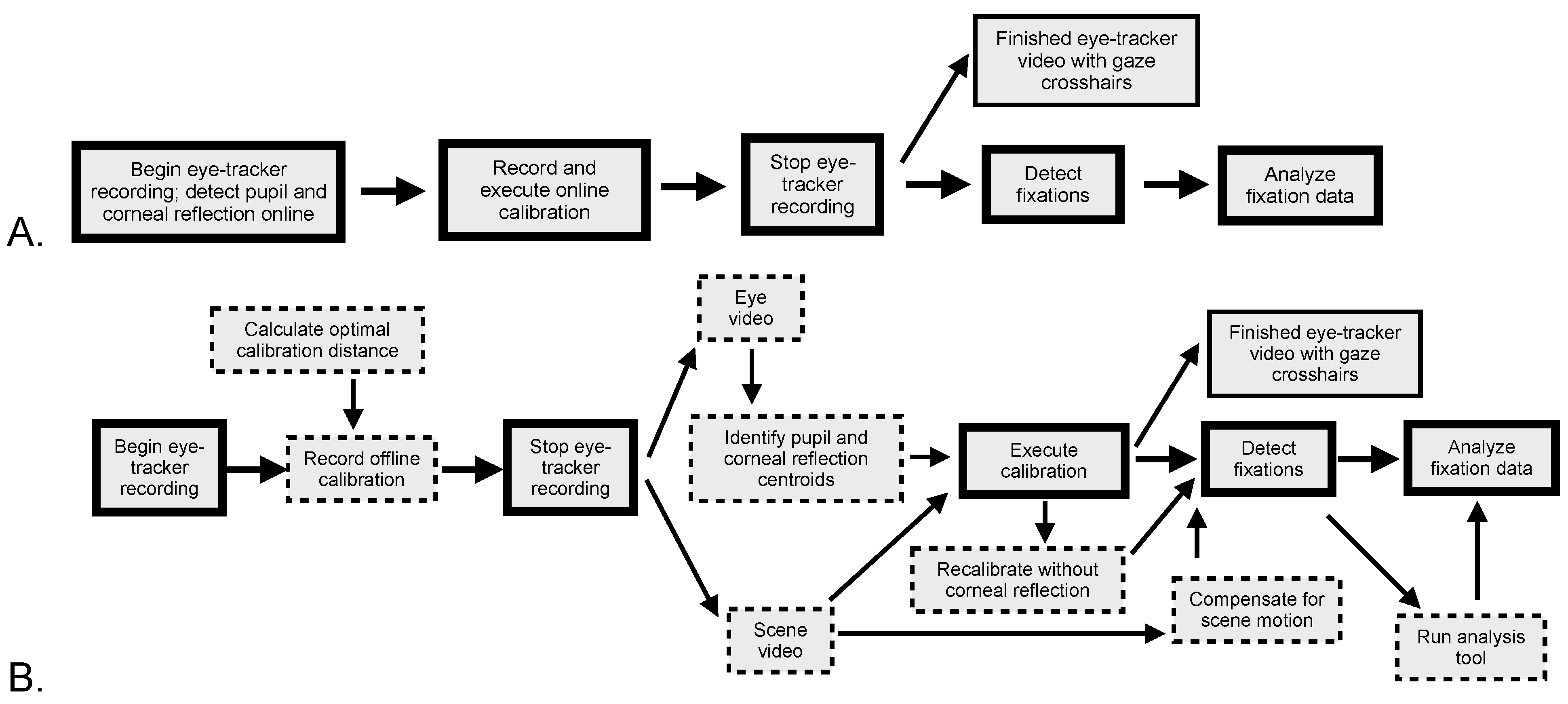
The method for a typical stationary eye-tracking study is presented in Figure 1A. First, the eye-tracker recording begins and initiates the search for eye features such as the pupil and corneal reflection which are tracked in real time as the recording continues. Next, the experimenters must calibrate the eye image and gaze location, in order to determine where in the scene the observer is looking; most stationary eye-trackers use an online calibration, meaning that gaze is estimated immediately, and can be shown during the experiment. The experiment is then conducted (perhaps with recalibration trials during the session), and afterwards the recording is stopped, producing an output video with gaze overlaid onto the scene. Next, the gaze information is divided into fixations (times when the eye position is stable) in order to determine when the observer is steadily looking at something. Finally, the fixation data are analyzed, in order to determine where and how observers direct their gaze over time, in different conditions, and relative to each other.

Figure 1.
Flowchart of eye-tracking methods in different environments. 1A shows the method traditionally used in stationary eyetracking, and 1B displays the stages of our method of outdoor mobile eye-tracking. Stages with dashed borders in 1B do not exist as separate stages (or at all) in stationary eye-tracking.
Figure 1B shows the method we have developed for outdoor mobile eye-tracking, and which is discussed throughout this paper. Apart from recording and conducting the experiment, all key stages from 1A are affected, with additional inputs being required, and some stages separated into different components. These changes reflect the fact that during outdoor mobile eye-tracking, eye features often cannot be tracked in real-time, it is usually preferable to compute the calibration offline, periods of steady gaze are not limited to eye fixations and are susceptible to variable noise, and gaze is not initially plotted onto a common coordinate space that facilitates comparisons across time and observers.
Hardware
Currently, many eye-tracking manufacturers offer mobile eye-tracking units. These systems consist of head-mounted recording devices that monitor the observer’s environment and one or two eyes, as well as a data storage unit that connects to the headgear directly or wirelessly. Almost all mobile eye-trackers are videobased systems, meaning that they record one video of ocular position and a second video of the observer’s surroundings, and use image processing to determine the observer’s point-of-regard (i.e., the coordinates in the scene camera view that correspond to the observer’s gaze location). Despite this key similarity, there are many differences between the available tracking units and the software packages that come with them, and selecting the best one depends on the intended applications.
Most mobile eye-trackers are designed to be comfortable even with extended wear, so that the observers can navigate their environments unencumbered and undistracted by the device. Such systems need to be lightweight and typically are able to record at 30–60 Hz with 1–2° of accuracy. If system weight and mobility are not critical, higher recording rates and even greater accuracy can be obtained with more bulky machinery.
The geology study requires that the tracker be suitable for long recordings and that it not restrict movement as the observers walk around the environment, examine rock samples, and take lecture notes and scene sketches. We use a video-based monocular recording system developed by Positive Science, in which cameras monitoring the eye and the scene are mounted to a lightweight set of eyeglass frames (design described in Babcock & Pelz, 2004). The eye camera (labeled B in Figure 2) sits on an adjustable arm positioned below the right eye and adjacent to a nearinfrared emitting diode (IRED) (labeled C in Figure 2). This equipment is visible to participants, typically obstructing <1% of the right eye’s peripheral field of view, though participants report acclimating to its presence quickly. The scene camera (labeled A in Figure 2) is mounted above the right eye, recording a color video that moves with the participant’s head and body. Wiring from the headgear connects to an ultralight laptop that the participant carries in a backpack (Figure 2, at right).
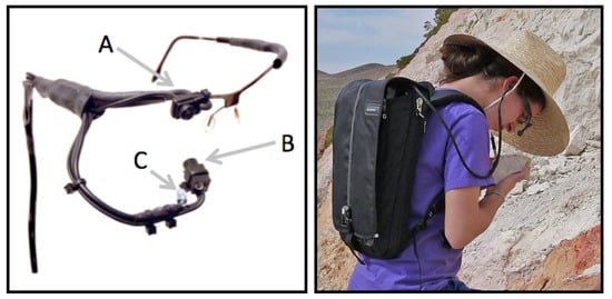
Figure 2.
Eye-tracking system used in our research. Headgear consists of a color camera (A) to capture the scene in front of the observer, a monochrome camera (B) pointing towards the right eye for monocular tracking, and a nearinfrared emitting diode (C) to illuminate the eye image and provide a first-surface corneal reflection. At right is an observer wearing the headgear and backpack.
Calibrating Eye Position and Point-of-Regard
Eye-tracker calibration is the process of relating ocular position to the location in space where the observer is looking. Typically, this procedure involves having the observer fixate on a series of points with known spatial coordinates. The position of the eye (which in most video-based eye-trackers is measured by the pupil center and corneal reflection) at each of these locations is then used to train the calibration software on the correspondence between eye position and the point-of-regard.
The eye-tracker’s calibration calculations can be completed online or offline. With an online calibration, the eye-gaze correspondence is entered into the eyetracking software as the participant views each calibration point. Online calibrations immediately take effect, and are used for all subsequent portions of the recording until another calibration occurs. As soon as an online calibrated recording is finished, the system outputs a single video with overlaid gaze crosshairs. In contrast, with an offline calibration, synchronized eye and scene videos are recorded as each calibration point is viewed, but the gaze calculations are not conducted during the recording. The initial output of such recordings is therefore two separate eye and scene videos; the videos are combined and gaze is calculated during a subsequent calibration stage.
Conceptually, calibration in stationary and mobile eye-tracking is the same, and the quality of the calibration is optimized by matching conditions such as lighting, eccentricity of targets, and distance from the observer, so that they are the same during the calibration phase and the experiment (e.g., Cerrolaza, Villanueva, Villanueva, & Cabeza, 2012; Holmqvist et al., 2011, section 4.5; Wyatt, 2010). In practice, however, they are quite different because control over these parameters is limited with mobile eye-tracking and especially when data are recorded in natural environments.
Method of Presenting Calibration Points
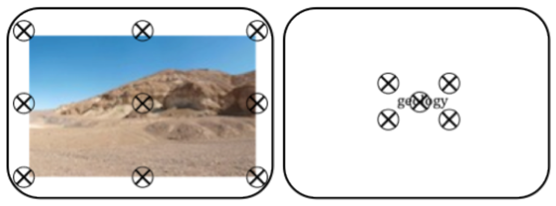
Ideally, experimenters could capture gaze correspondence data for all possible eye positions, yielding a very precise calibration. Presenting such a dense array is impractical, and so experimenters instead calibrate a subset of possible eye positions, and then use these data to calculate an estimated gaze location for other eye positions. Gaze calculations that interpolate between calibration points are more accurate than those that must extrapolate beyond existing data, and so calibration points are typically positioned so that they cover the full area in which stimuli will be presented. When stimuli are presented on a computer monitor and head position is fixed, this requirement is easy to satisfy: the most eccentric calibration points usually form a rectangle with borders that slightly exceed the location of experimental items, and a few additional points may appear in the middle (Figure 3).
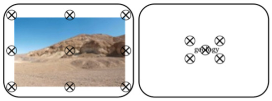
Figure 3.
Sample calibration points for computer-based eyetracking studies. Calibration points extend just beyond the stimulus borders, covering the full screen in experiments with large stimuli (nine-point array at left) and a reduced area for smaller stimuli (five-point array at right).
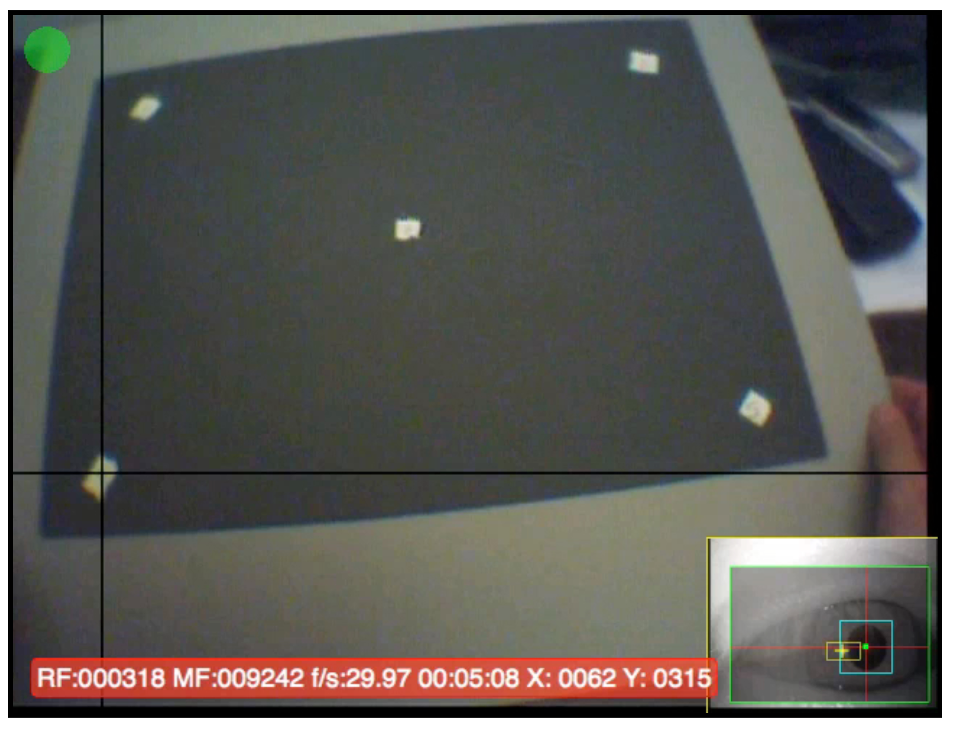
When the observer’s head is not fixed during the experiment, calibration points need to be positioned to cover the range of expected eye positions rather than the stimulus area. For mobile eye-tracking studies in which participants make only a limited range of eye movements (e.g., while working on a computer or manipulating small objects), a static point array comparable to those presented on computer monitors is sufficient (Figure 4). Target positions on a static point array are only meaningful if observers hold their heads still and move only their eyes during the calibration; if they also move their heads, this reduces the visual angle separating calibration points, so that a smaller range of eye positions are included in the calibration.

Figure 4.
Static point array method for conducting a fivepoint calibration on mobile eye-trackers. In this video still from research conducted our laboratory, observers who were tracked while assembling a small device viewed five calibration stickers affixed to a hand-held board.
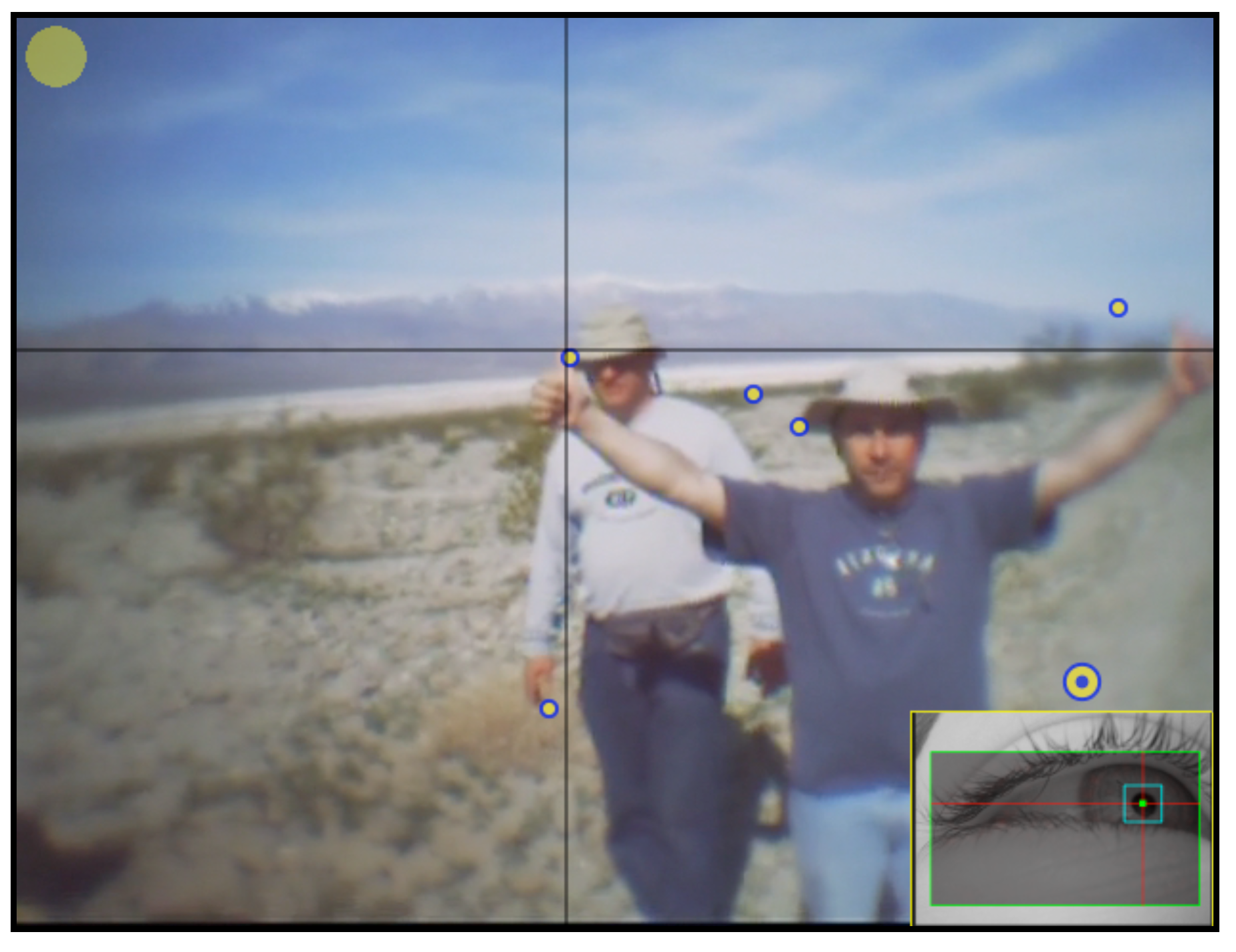
If a larger range of eye movements needs to be calibrated, observers can watch a moving target that stops at specific positions to create a five-point or ninepoint calibration. In some of our mobile eye-tracking studies, observers calibrate by watching a person’s thumb move to different locations (Figure 5). However, the locations where the target pauses are hard to standardize: these locations are influenced by the partner’s arm span (which covers only a small part of the scene view at farther distances), differences in the partners’ heights, failure of the partner to fully extend his or her arms, poor centering (e.g., the points in Figure 5 are anchored to the right), and head movements.
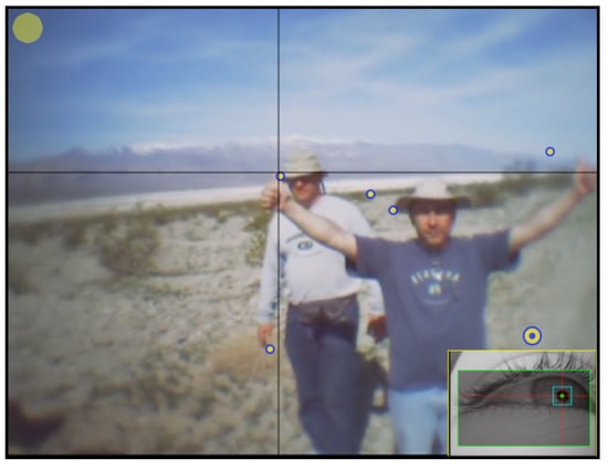
Figure 5.
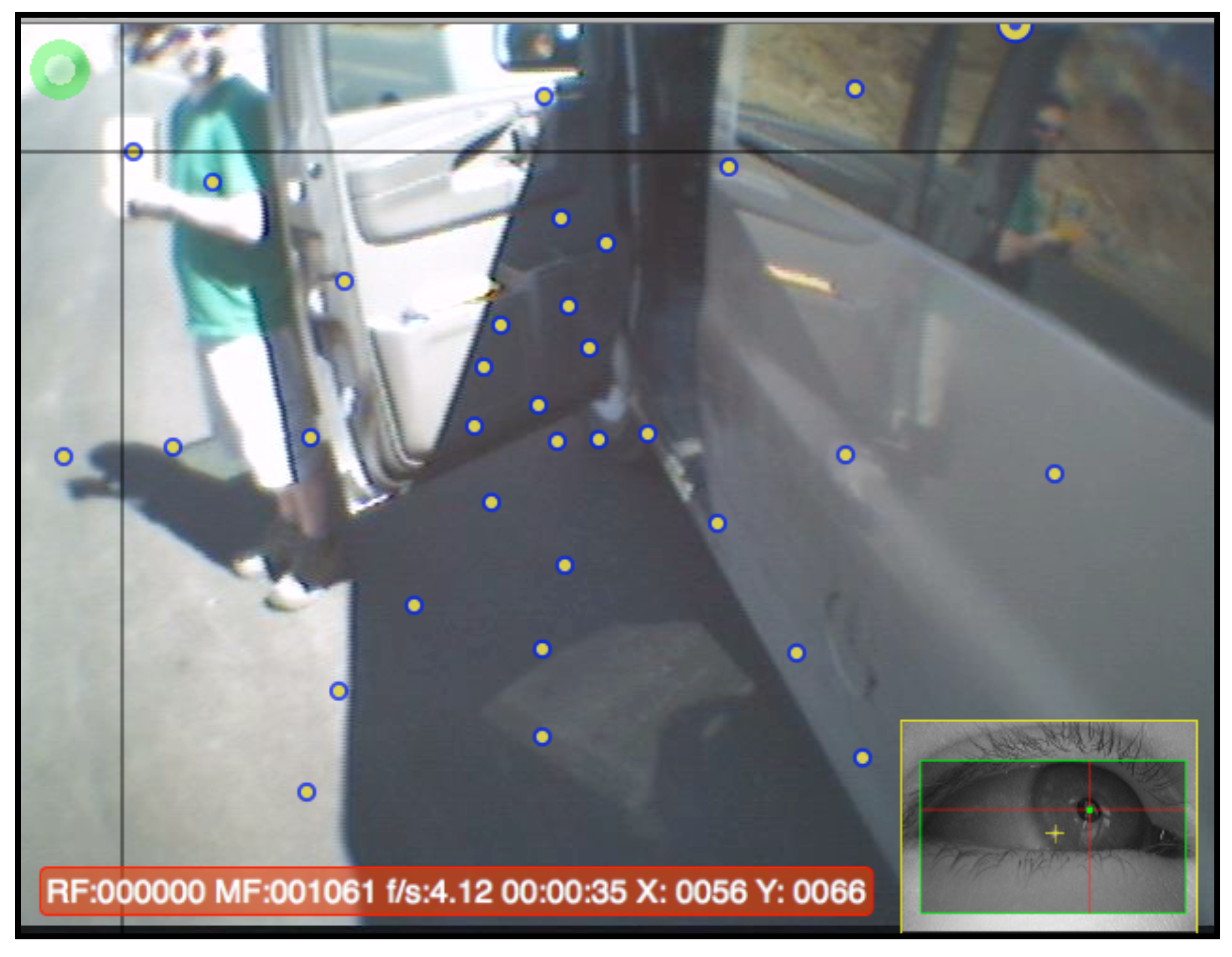
Moving target method of five-point calibration. Observers who were tracked outdoors followed a partner’s moving thumb, which paused at positions that create a fivepoint calibration (indicated by overlaid circles).
For studies in which a broad range of eye movements are expected, we recommend having observers fixate a stationary calibration target while moving their heads in small ‘robotic’ ticks. To complete this type of calibration, observers would start by facing the target, then turn their heads approximately 10° to the right while maintaining fixation on the target. After a brief pause, they would turn their head another 10°, pause for another fixation on the target, and continue this process until five head ticks have been executed. With each successive head tick to the right, the eyes move farther to the left in order to fixate the target, allowing a broad range of eye positions to be calibrated.
We have participants make these head ticks to the left and right, up and down, and across the four diagonals (thus creating a ‘plus sign’ and an ‘x shape’), with about five head ticks from the center to the extreme on each side. Across all eight directions, this method tends to yield 25–30 fixation points, which broadly cover the scene in an asterisk-like pattern (as shown by the dots in Figure 6; note that the most extreme head ticks are excluded because an observer’s field-of-view is broader than that of the scene camera). This method does not require a partner or even equipment beyond a target (an object in the environment can be used), and so observers can calibrate themselves. Moving the head to a single, stationary target has also been recommended for instances where target visibility is poor, or when the clarity of eye features needs to be carefully monitored (Holmqvist et al., 2011, section 4.5.7).
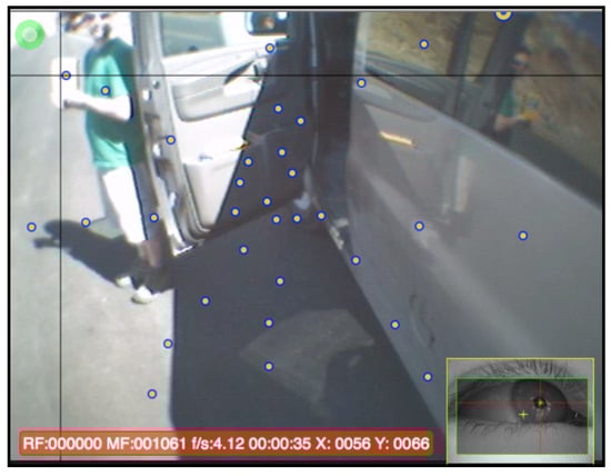
Figure 6.
Head tick calibration method. The observer is looking at a stationary target held by a partner, and the dots indicate all positions the observer paused for a head tick.
We compared the moving target and head tick methods by conducting a study in which eight participants completed both a moving target and a head tick calibration (order was counterbalanced across participants) and then viewed a series of targets. Thirteen targets were located at the center of the display, and an additional twelve targets were located more peripherally. While viewing the targets, participants kept their heads steady and moved only their eyes in order to capture a range of eye positions. Because we used an offline calibration, accuracy calculations used the same gaze data for both conditions. We calculated the average fixation error (i.e., difference between estimated point-of-regard and true location of the calibration point), and compared these values in a 2 (Method: moving target, head tick) x 2 (Location: central, peripheral) x 2 (Dimension: horizontal, vertical) repeated-measures ANOVA. Data are shown in Table 1.

Table 1.
Mean calibration error (in degrees of visual angle) and time for moving target and head tick methods, averaged across 13 central points and 12 peripheral points.
Not surprisingly, accuracy was greater at the central points (averaging 0.57° error horizontally, and 0.61° error vertically) than peripheral points (averaging 1.14° error horizontally and 1.40° error vertically), and this difference was significant (F(1,7) = 51.48, p < 0.001). Accuracy of the two calibration methods did not significantly differ (F(1,7) = 2.49, p > 0.1). However, a significant Location x Method interaction revealed that the head tick method was more accurate than the moving target method for peripheral points, but the two methods were similar for central points (see Table 1, F(1,7) = 6.74, p < 0.05). A marginal interaction of Method x Dimension (F(1,7) = 3.87, p < 0.10) reflected a trend in which horizontal and vertical errors were nearly equivalent for the moving target method, but smaller horizontally for the head tick method. No other comparison approached significance.
We additionally calculated the duration of each observer’s calibration sessions (i.e., the time to execute the calibration; this did not include the time to describe it to the participant), verifying that the moving target method is faster than the head tick calibration (t(7.15) = 3.91, p < 0.01, with correction for unequal variances, see Table 1). Together, these results suggest that when observers are primarily looking at objects in the center of their visual field, the shorter moving target calibration method can be used without compromising accuracy, but that when observers will be looking at both central and peripheral targets, the longer head tick method should be used.
Calibration Target
In all eye-tracking studies, it is best to use a calibration target that participants will fixate in only one area. Common targets therefore tend to be small and to have a clear focal point, such as the intersection point of an X. For indoor mobile eye-tracking studies or when calibrating at a close distance, a small X remains effective. For calibrating at farther distances, we recommend the use of a target that is about the size of a fist and that has a single, central, high-contrast focal point. For outdoor studies, we print the design in Figure 7 with a 6 cm diameter. We have found that observers are able to locate the center of this target even when it is placed at eccentric positions and several meters away, and that experimenters reviewing the scene video can easily locate the target itself (the target’s center is sometimes washed out by reflected sunlight, but experimenters can still select the center of the visible target).
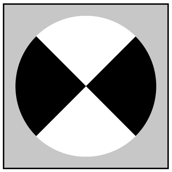
Figure 7.
Calibration target used in our outdoor studies. In
Figure 6, the target is pasted to a geologist’s field notebook.
Calibration Distance
In head-mounted eye-trackers with direct-view scene cameras, there is an offset between the location of the eye (which actually views the scene) and location of the scene camera (which experimenters use as a proxy for the eye’s view). This offset introduces the possibility of parallax error when the point-of-regard is calculated. To avoid this offset, it is possible to merge the observer and scene camera view vectors by placing a half-silvered mirror in the observer’s optical path (e.g., Land, Mennie, & Rusted, 1999), but in bright outdoor environments this reduces the quality of both scene video and the observer’s view. Most wearable eye-trackers position the scene camera either directly above the tracked eye (introducing vertical parallax error) or centered above the nose (introducing both horizontal and vertical offsets).
In the eye-tracking system used in our study, the scene camera is positioned approximately 2 cm above the tracked eye of the observer. Vertical parallax for this configuration is illustrated in Figure 8. If the calibration targets are presented at distance C, then the vertical offset is accounted for during the calibration, and all stimuli presented in plane C are aligned. At all other distances, the scene video and eye’s view are no longer aligned, and vertical parallax error occurs.
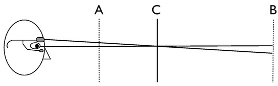
Figure 8.
Parallax error at different distances. If the calibration occurs along plane C, then this offset would be corrected at other points along plane C, but would not be sufficiently corrected at closer depths (plane A) and would be overcorrected at farther depths (plane B).
To eliminate parallax errors completely, the experimental stimuli must all appear along a single depth plane at which the calibration points also appear. Satisfying this constraint is easy when all stimuli and calibration points are presented on a computer screen and the observer maintains a fixed head position. This becomes more difficult with mobile eye-tracking outside the laboratory, where fixated objects may appear at a variety of distances and participants can move closer to or farther from these objects during the recording.
Parallax error can be corrected if the depth of fixated objects is known. Dynamically tracking depth to sufficient accuracy is a challenge in video-based systems, though some head-tracking tools may be able to offer appropriate corrections (Holmqvist et al., 2011, section 2.7.5). If tracking binocularly, the extent of ocular convergence can be used to track the distance of focused objects, but the correction is only practical at close distances given the accuracy of video-based eye-trackers. For example, an observer fixated on an object 2 m away, tracked with binocular trackers with angular accuracies of +/-1°, provides an uncertainty in fixated depth between ~1 m and infinity. In cases where there is only horizontal parallax error and both eyes are tracked, averaging the gaze estimates for each eye can also minimize parallax error (Holmqvist et al., 2011, section 2.7.5).
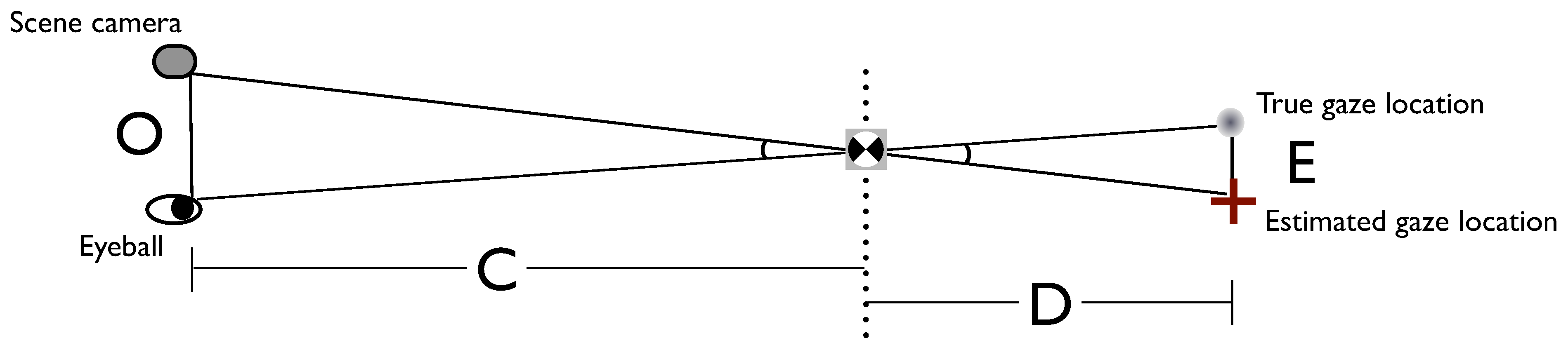
When eliminating or correcting parallax error is not feasible, it is important to select a calibration distance that minimizes parallax error at the range of target distances that is expected in the experiment. Knowing the size of the eyeball-scene camera offset (O) and the distance of calibration plane (C), one can calculate the size of parallax error (the difference between true gaze location and estimated gaze location that is expected to occur due to parallax, E) at any distance from the calibration plane (D): E = OD/C (Figure 9). Using this formula, researchers can calculate the amount of parallax error (which should then be converted to degrees of visual angle), and determine the best calibration distance for minimizing these errors for all expected experimental conditions. In general, the impact of parallax error on eyetracker accuracy will be smaller at distances farther than the calibration plane than at those closer to the observer, because although the Euclidean size of parallax error continues to increase at farther distances, the angular size of these offsets remains quite small.
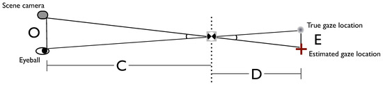
Figure 9.
Calculating parallax error. The amount of parallax error (E) for a mobile eye-tracker can be calculated for any distance from the calibration plane (D), when the distance between the calibration plane and the observer (C) and size of the offset between the scene camera and eyeball (O) are known. Geometrically, E/D = O/C, and therefore E = OD/C. This formula holds regardless of whether gaze is being calculated at distances beyond the calibrated plane, or at distances between the observer and the calibrated plane.
For the geology study, we were interested in fixations to distant objects of varying depths, so we calibrated at 5 m. With 2 cm of vertical offset, this limits vertical parallax error to 0.25° of visual angle for objects between 2.5 m and infinity, but introduces unacceptably large error at closer distances. We therefore did not analyze fixations to nearby objects (e.g., the professor or other students). In studies where fixations to both near and far objects are important, it is possible to perform two different calibrations, if the eye-tracker supports offline calibration. For example, in a driving study conducted at the Rochester Institute of Technology, observers recorded one calibration at the dashboard and another approximately 5 m away. Using offline calibration software, gaze inside the vehicle was processed with the dashboard calibration and gaze outside the vehicle used the distant calibration.
Calibration Frequency
During a mobile eye-tracking experiment, the headgear can sometimes slip or be bumped (even with a properly fastened head strap) and this risk increases over time and when participants are being physically active. A shift in headgear position will increase error in the point-ofregard calculation and can invalidate the calibration if the eye’s position in the video image shifts significantly. Tracking the corneal reflection (i.e., the glint produced by the IRED’s reflection off the eye) can reduce these errors because the pupil-corneal reflection vector is relatively invariant to changes in the eye camera’s position (Merchant & Morrissette, 1974). However, this correction is only approximate (Li, Munn, & Pelz, 2008), it does not compensate at all for movement of the scene camera attached to the headgear (which compromises the parallax correction), and the corneal reflection signal is difficult to maintain in outdoor environments (see next section). Headgear movement can be corrected by immediately recalibrating, but observers and experimenters do not always notice movement or slippage. It is therefore essential to record multiple calibration sessions at different points in the tracking session. Recalibrating is common practice in laboratory studies, and remains critical during mobile eye-tracking. In our studies, we always perform calibrations at the start and the end of each tracking session, and we record intervening calibrations if the participants perform any physical activity (e.g., climbing up a hill), wear the trackers for a long period of time, or if an individual reports headgear movement.
For outdoor eye-tracking, we recommend calibrating offline because it allows the experimenter to select the calibration session that is best aligned with the headgear’s current position for all parts of the video. For example, an observer who accidentally bumps the headgear may not notice this event, but an experimenter who views the videos offline can detect the sudden change in eye position and concurrent jostling of the scene video. The experimenter can then select the next calibration in the video, and apply it to all post-headgear movement segments. With online calibration, these headgear movements must be detected as soon as they occur, or else the previous calibration will continue to be applied and all new data will have invalid point-of-regard values. We also recommend the use of occasional calibration checks in which the observers fixate a single target once (rather than performing a full calibration). When reviewing the videos offline, experimenters can use poor gaze alignment to these checkpoints as a signal to recalibrate to the next calibration. Calibrating offline also facilitates simultaneous data collection from multiple observers, because it removes the time-consuming requirement that experimenters enter each calibration point as it is viewed for all of the observers being recorded.
Calibration Summary
For both indoor and outdoor recordings, optimizing the quality of a mobile eye-tracker calibration requires knowledge of the expected locations and distances of fixated items, in order to select the most appropriate method, a distance that minimizes parallax error, and targets that are visible. Multiple calibration sessions should be recorded, and if headgear movement is likely, these should be reviewed offline. In selecting an eyetracker, experimenters should attempt to minimize parallax error, consider the amount of headgear movement (e.g., whether the headgear has straps, rubber grips, or can adjust to fit different head sizes), and if conducting long or active tasks, select a system that supports offline calibration.
Tracking Eye Features
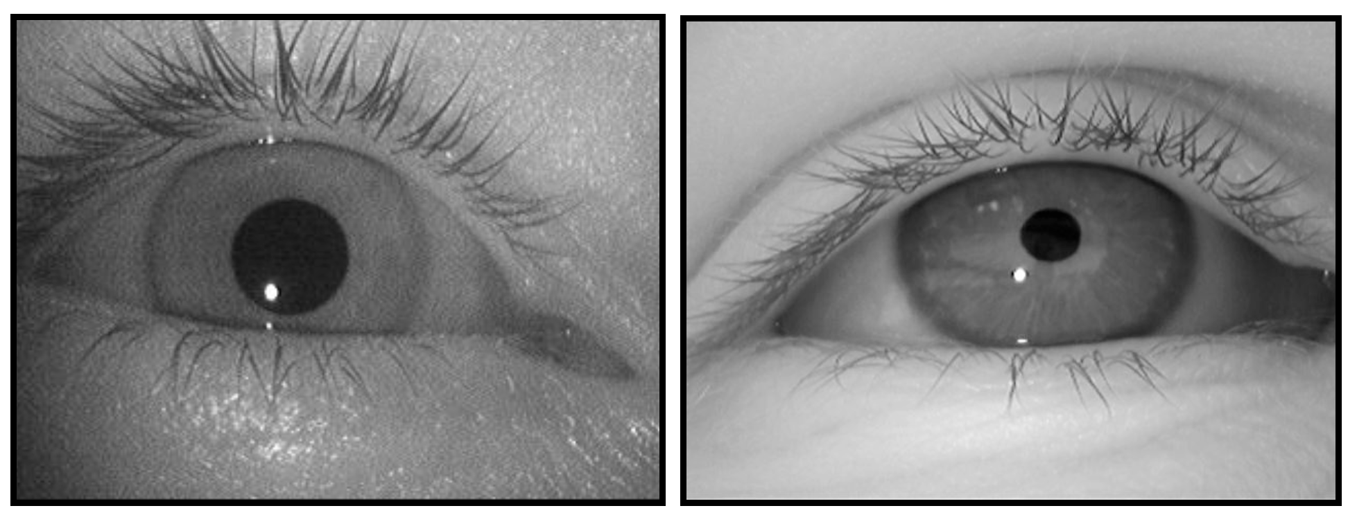
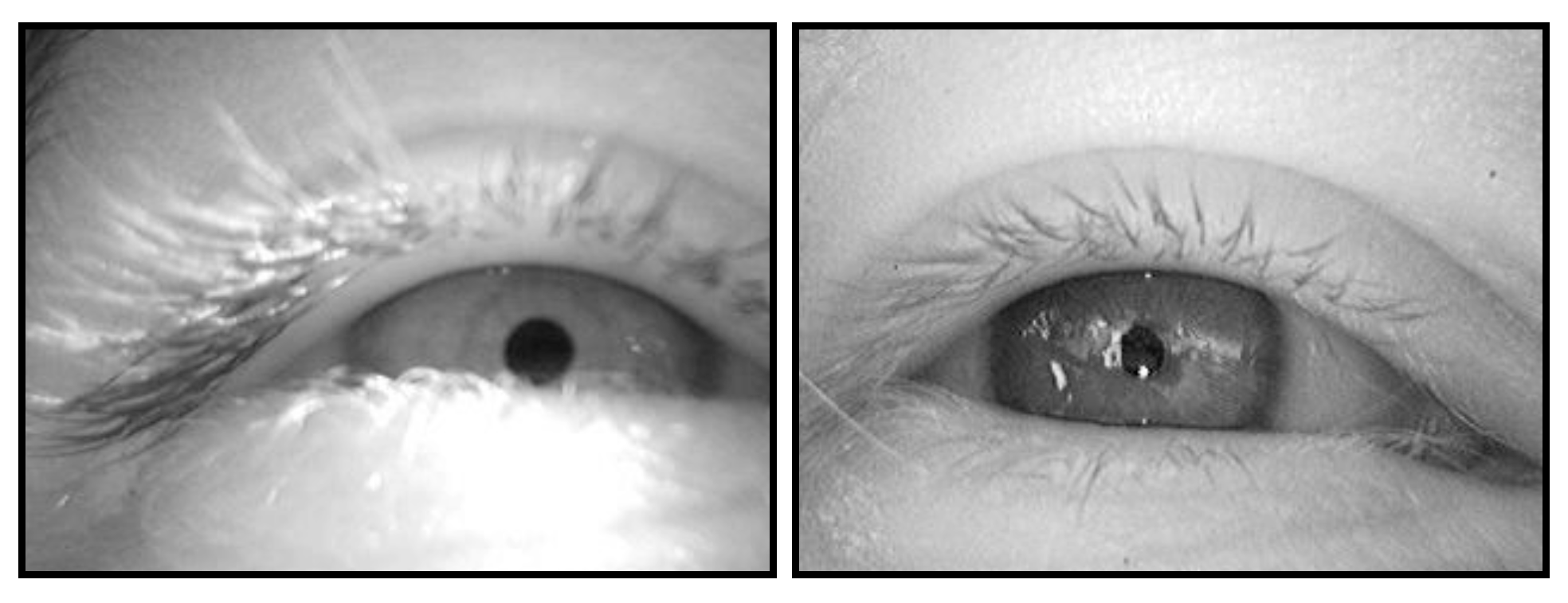
In most video-based eye-tracking systems, eye position is measured by either the center of the pupil, or by the difference vector between the pupil center and the corneal reflection (P-CR). Contact lenses do not distort these signals, and even eyeglasses can be worn with the headgear, provided that reflections off the eyeglass lenses are minimal. P-CR tracking can be performed indoors (Figure 10, left) and also outdoors (Figure 10, right), where sunlight causes the pupil to constrict.

Figure 10.
Clear images of the pupil and corneal reflection, captured from a wearable eye-tracking system indoors (left) and outdoors (right).
Image Capture
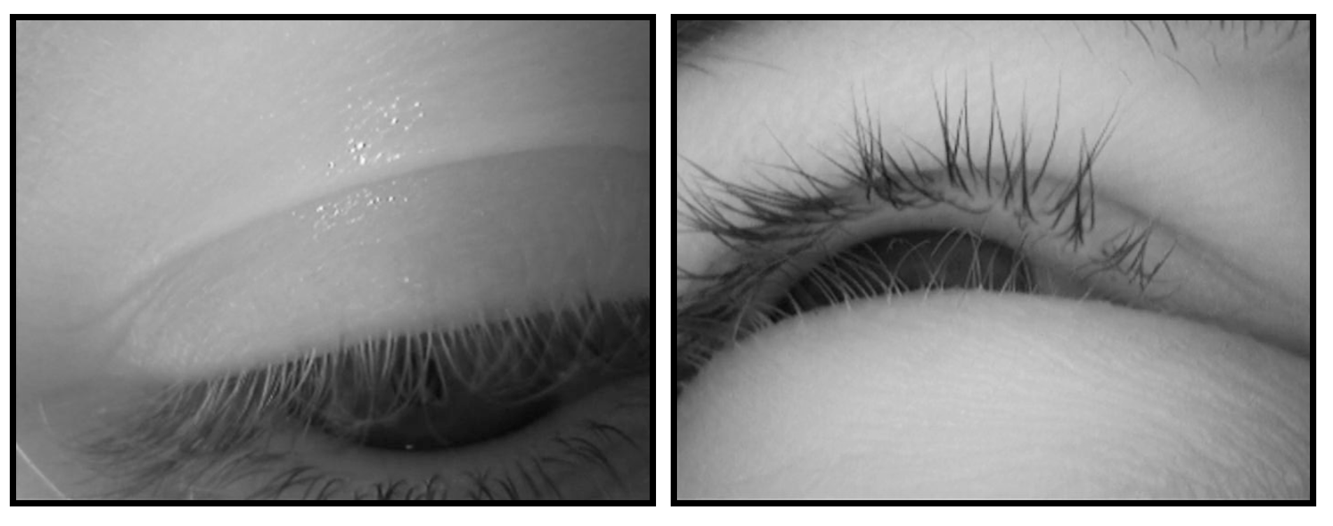
Image-based tracking requires that the eye camera be positioned so that the pupil remains visible in the recording. We use an eye camera with a 36° x 25° field of view and have found that the camera’s position and range captures all horizontal eye movements, but that extreme vertical eye movements (looking directly overhead or down at the ground) are often obscured by the eyelids and eyelashes (Figure 11). Orienting the eye camera at a higher or lower angle will improve pupil visibility for these eye positions, but capturing both extremes requires more than one camera. For the geology study, we positioned the eye camera so that the pupil was vertically centered when observers looked straight ahead. This allowed most eye movements on the scene to be captured, but meant that we could not simultaneously track lower fixations when observers took notes or looked at the ground while walking. Fixations overhead were also difficult to track, but these were extremely rare in our study.

Figure 11.
Track loss due to eye position. With the eye camera positioned to optimize fixations on objects directly in front of the observer, eye movements directed to the ground (left) and far overhead (right) cannot be tracked.
Outside, the visibility of eye features can also be compromised by natural infrared light flooding the eye camera. To prevent this problem, we have outdoor participants wear large-brimmed straw hats to block most of the overhead lighting. This is not necessary on cloudy days, but in direct sunlight, a hat must be worn in order to capture an eye image with visible, trackable features.
Pupil Tracking
The eye-tracking software of video-based dark-pupil tracking systems identifies the pupil by searching for a round and dark part of the eye image. It is possible to capture a clear pupil image outdoors, but natural lighting introduces several challenges. Observers tend to squint in outdoor lighting, causing the lower eyelid and eyelashes to partially or fully occlude the pupil (Figure 12, left). When partially obstructed, the visible portion of the pupil is not round and is brightened by eyelashes, making it difficult for a search algorithm to detect. Additionally, even when overhead lighting is partially blocked by large-rimmed hats, ambient light can reflect off the cornea and may brighten the pupil (Figure 12, right).
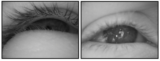
Figure 12.
Challenges to pupil tracking in outdoor environments. Natural light can produce squinting that obstructs the pupil (left) and reflections that reduce the pupil’s relative darkness (right).
Most current pupil detection software is not designed to handle these challenges. In fact, software that supports online calibration is designed to detect the pupil in realtime, meaning that its detection algorithms must work in pace with the frame rate (typically 30–60 frames per second). At such speeds, the search parameters are limited and less likely to be effective for non-canonical eye images. An advantage of offline calibration (which also means offline detection of eye image features) is that the detection software can use more time-consuming but effective search algorithms. For example, many tracking tools allow users to restrict the pupil search area so that dark corners and areas such as mascara-covered eyelashes can be ignored. We use a version of Positive Science’s offline tracking software that allows users to override erroneous or missed detections by manually locating the pupil (and corneal reflection, if needed). This is similar to manual iris-tracking techniques employed by other researchers (e.g., Land & Lee, 1994; Land et al., 1999), but is integrated with automated search algorithms; in the current version of the software, experimenters monitor the success of automatic tracking and can override it with manual tracking or forced track loss as needed. To our knowledge, no existing automated algorithms can successfully track eye features when squinting or reflections are present.
When the pupil cannot be detected, these segments of the recording may be reported as track loss, or the search algorithm may track darker areas such as eyelashes or the corner of the eye as the pupil. Issues such as squinting and ambient reflections are also problematic during indoor stationary recordings (reviewed in Holmqvist et al., 2011, section 4.4), but they are sufficiently rare indoors that the errors or track losses they introduce are acceptable. The amount of data that is lost due to these issues during outdoor tracking varies dramatically across individuals as well as environmental and stimulus conditions. Of the 37 observers we have tracked in the geology study to date (2010–2012), seven frequently squinted at every outdoor site, and five of these observers also participated in an indoor tracking session, and did not squint there. In addition to these personal tendencies, all observers are more likely to squint and to have reflections on the eye image on especially bright days and when scene features such as snow or water reflect sunlight.
We examined a sample of 82 outdoor videos from the geology study, and found that 16 had prolonged squinting, 14 had frequent reflections, and 11 had a combination of both of these issues. The other 41 recordings had a clear eye image through most of the video. These rates may not be representative of all outdoor eye-tracking, as our recording conditions may differ from those encountered in other studies.
In order to more precisely examine the amount of data loss under these conditions, we ran 10 mostly clear videos, 10 squinting videos, 10 reflection videos, and 10 videos from an indoor study through both the Positive Science automatic pupil-tracking software and the Positive Science assisted coding software, which allows manual override when the pupil is not identified correctly or at all. After pupil detection, these pairs of videos were then run through our fixation-finding software, in order to determine how much usable fixation data was generated by each detection method. (This measure excludes not only track loss, but also blinks, saccades and fixations too brief to be detected. This is preferable to reporting pure track loss, because it excludes false alarms to other dark spots such as eyelashes and dark shadows; these incorrect detections are not reported as track loss, but tend to be too noisy and unstable to be detected as fixations. Comparing the amount of time spent in fixations is therefore a more direct assessment of pupil detection.) We then calculated the proportion of fixation time for each recording (i.e., the total time spent in fixations divided by the total duration of the recording; Table 2), and compared this value for the two tracking methods in a mixed-model ANOVA with the between-groups variable Video Type (indoor, outdoor clear, outdoor squinting, outdoor reflections) and within-group variable Detection Method (automatic, assisted). A difference between methods would suggest that the assisted software was able to recover data that were omitted from the automatic software (i.e., instances where the pupil is detected by human operators but not by standard algorithms), whereas a lack of difference would suggest that assisted detection does not reduce track loss rates.
Table 2.
Proportion of recording time spent in (detected) fixations. Raw data and t-tests comparing fixation time with automatic versus assisted detection methods are shown below. Assisted detection does not influence the amount of time spent in fixations for indoor videos, but increases the proportion of fixation time for all outdoor videos, including those with a mostly clear eye image.
Overall, a larger amount of fixation data was detected with the assisted software (F(1,36) = 59.72, p < 0.001), and the proportion of time spent in fixations differed across Video Type (F(3,36) = 14.26, p < 0.001). A significant Detection Method by Video type interaction (F(3,36) = 13.69, p < 0.001) was examined in planned comparisons. This analysis revealed that assisted coding did not impact the time in fixations for indoor data, but led to a significant increase for all outdoor videos, and this increase was especially large for videos with frequent squinting (Table 2).
These results demonstrate that there are many instances where the pupil is visible to humans (e.g., Figure 12), but hard to detect with automated search tools. For mobile eye-tracking studies in which unusable data can easily be replaced or tracking sessions can be canceled when lighting is too bright, dropping participants with unusable data may be acceptable. However, for studies in which data collection opportunities are infrequent or expensive, the ability to recover these data by some means is critical.
Corneal Reflection Tracking
The corneal reflection (which is visible in the eye video as a small bright circle, seen in Figure 10), is detected via a brightness threshold. Corneal reflection track loss and errors due to squinting, ambient reflections, and extreme eye positions occur during indoor and stationary eye-tracking (reviewed in Holmqvist et al., 2011, section 4.4), but bright sunlight increases the frequency of these problems outdoors. Because the IRED is positioned below the right eye, the corneal reflection is always on the lower half of the eyeball, and even moderate squinting that does not affect pupil visibility can block the corneal reflection (Figure 13, left). In many of our outdoor videos the corneal reflection is intermittently visible because of squinting, and in about a third of our videos the corneal reflection in obscured in virtually all frames of the recording. Even when the IRED’s reflection is visible, other reflections off the eyelid or cornea can be mistaken for the IRED’s corneal reflection (Figure 13, right).
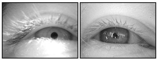
Figure 13.
Challenges to corneal reflection tracking. At left, the corneal reflection is not visible (even though the pupil is), but sunlight reflecting off the eyelashes and lower eyelid is bright enough to be mistaken for a corneal reflection. At right, the IRED’s corneal reflection is visible, but is difficult to distinguish from the equally bright environmental reflections.
When software cannot detect a corneal reflection, most mobile eye-trackers will default to gaze estimates based just on the pupil centroid; in such cases, inability to track the corneal reflection may reduce spatial accuracy, but does not produce data loss. However, some systems require a steady corneal reflection track and would thus produce no data for these frames. False positives in the corneal reflection track are also problematic. The IRED’s corneal reflection comes from a fixed source (i.e., neither the IRED nor the arm supporting it move during the recording), and so its position in the eye video is fairly stable. If the software falsely tracks an ambient reflection on the eyelid or other location that is far from the IRED’s reflection, the resulting gaze estimate will be significantly inaccurate. There are some tracking tools that help avoid false positives by restricting the corneal reflection search area to the most likely positions (given the IRED corneal reflection’s stability) and allowing users to disable the corneal reflection search for videos in which the IRED reflection is never or only rarely visible. These functions varies are not available on all eye-trackers, but are essential for outdoor eye-tracking.
Tracking Summary
Squinting and reflections interfere with both pupil and corneal reflection detection in any type of eye-tracking environment, but are especially likely outdoors. Manufacturers may soon offer tracking software that is optimized for outdoor conditions, but for now, some amount of track loss should be expected. It may be possible to avoid tracking errors by limiting the environment (e.g., tracking in shady areas or planning ahead and tracking on overcast days), limiting the observers (e.g., having an outdoor pretest to identify and exclude frequent squinters), or running extra observers so that those with excessive data loss can be dropped and replaced.
In selecting a tracking unit, it is important to check that the eye camera’s position is either adjustable or in a fixed position that captures critical eye positions. Additionally, researchers planning to collect outdoor data should ensure that the headgear can be worn with a hat, that the software can estimate gaze from the pupil alone when corneal reflection fails, and that there are some features to reduce false positives during corneal reflection tracking.
Detecting Fixations
Rather than analyze every sample of an eye-tracker’s recording, experimenters tend to focus on the periods of time when observers are steadily looking at a single area. Reducing data to steady gaze is appropriate given that observers apprehend no new visual information during saccades (Irwin & Carlson-Radvansky, 1996; Matin, 1974) and experience backward masking immediately after each saccade (Raab, 1963). Therefore, most stationary eye-tracking studies analyze only the periods of time in which observers’ eyes are steady.
Most fixation-detection algorithms find fixations by setting two thresholds: the first threshold determines how much dispersion is allowed within one fixation (e.g., if the pupil center or point-of-regard moves more than five pixels between adjacent frames, the current fixation is over) and the second threshold determines how long that signal must remain under the dispersion threshold in order for a fixation to have occurred (e.g., there must be at least 60 ms of steadiness for it to be labeled a fixation). The modest frame rates of mobile eye-tracking units (3060 Hz) are sufficient for this method, but too slow for alternative approaches such as saccade velocity tracking (Salvucci & Goldberg, 2000). However, using a dispersion threshold for mobile eye-tracking requires additional considerations not needed for stationary tracking.
Excluding the Corneal Reflection
As mentioned previously, when the corneal reflection is visible in the eye image, the positional difference between its center and the center of the pupil can be used to calculate the point-of-regard. Including the corneal reflection in the point-of-regard calculation can improve spatial accuracy, but offers no advantages when calculating the temporal characteristics of eye movements. In fact, the corneal reflection can distort fixation detection. The corneal reflection appears small in the eye image, and calculating the centroid of such a small signal is highly vulnerable to noise in the camera, especially noise due to video interlacing. By comparison, centroid calculations of the much larger pupil are more robust against the same sources of video noise. Point-of-regard estimates based on P-CR vector will therefore be noisier than those based only on the centroid of the large pupil. This presents a problem for fixation-finders that apply a dispersion threshold to the point-of-regard, because the added noise influences the number and duration of detected fixations.
In a sample of 20 outdoor videos with a visible corneal reflection, we compared fixation-detection when the point-of-regard was based on the P-CR vector to fixationdetection when the corneal reflection tracking was turned off, and point-of-regard for the same recording was based on the pupil alone. Using the P-CR signal significantly increased the number of fixations detected (from 265 to 302; t(19) = 6.00, p < 0.001), and decreased their mean duration (from 293.4 to 221.6 ms; t(19) = -12.93, p < 0.001). This large difference in basic fixation statistics could easily bias the interpretation of data if the proportion of subjects with a visible corneal reflection differs across experimental conditions. Simply raising the noise threshold for the fixation finder (e.g., allowing 12 pixels of deviation in the point-of-regard signal when there is a visible corneal reflection, but allowing 8 pixels when only the pupil is tracked) would accommodate the added noise, but is an inadequate solution because many outdoor videos have an intermittent corneal reflection signal; the increased threshold would be applied to the entire video, causing segments with a visible corneal reflection to have an appropriate threshold setting, but segments with only the pupil to have too high of a threshold to detect short fixations.
It is imperative to base the timing of fixations on the same information for all subjects and for all portions of each video. Given that the loss of the corneal reflection signal is common in outdoor studies, dispersion thresholds for such research must be based only the pupil (either movement of the pupil centroid, or movement of a point-of-regard that is calculated only from the pupil).
We calculate the location of fixations using the P-CR vector when it is available, but to determine fixation timing, we use a dispersion threshold that requires a minimum of three frames (approximately 100 ms at 30 Hz) in which the point-of-regard coordinates (which are based just on the pupil center) move no more than eight pixels (0.9°) between adjacent frames. We set these thresholds after extensive testing revealed that the eight-pixel threshold is low enough to capture most saccades but high enough to allow some jitter in eye position, as well as some (slow) smooth pursuit eye movements (which would be excluded from a threshold that considered dispersion across the duration of the fixation, rather than adjacent frames). The three-frame criterion is high enough to exclude noise but low enough to capture most fixations, though some shorter fixations (which cannot be confidently discriminated from noise at a 30 Hz frame rate) are likely omitted.
Correcting for Head Motion
During a stationary eye-tracking study with fixed head position, the pupil is always in a stable position (though with some small jitter) when gaze is steadily directed towards a single stimulus. (An exception is smooth pursuit, in which a slowly moving target is tracked, but this requires an eliciting stimulus that is rare in natural environments.) When head movements are permitted, steady gaze can also occur during vestibulo-ocular reflexes (VOR), which are eye movements that stabilize gaze during head and body movements. Consider, for example, maintaining fixation on a communication partner while nodding: when this happens, eye movements compensate for the head motion and keep the interlocutor’s face foveated. Similarly, when scanning a broad area or horizon, observers tend to rotate their heads and bodies while also moving their eyes. As this happens, the eyes do not glide smoothly across the horizon (though it may feel that way to the observer). Instead, these scans consist of a series of steady gaze (during which the head and eyes move synchronously and in opposite directions in order to maintain fixation on a single location) alternating with saccades (where the head and eyes move in the same direction and gaze is redirected to a new location).
A dispersion threshold fixation detector that seeks steadiness in the pupil or point-of-regard will not detect steady gaze during VOR, because neither the pupil nor the point-of-regard is stable. Fixation detection methods that were developed for stationary eye tracking are thus insufficient to capture all instances of steady gaze in mobile eye-tracking. Instead, a measure of eye-in-space or eye-on-stimulus stability (Holmqvist et al., 2011, p. 150; Land, 1999) is needed, but is hard to monitor when the stimuli move with head position. Across a variety of complex tasks that elicit eye and head movements, Land and colleagues have extracted fixations directly from the scene video (e.g., Land et al., 1999; Land & Lee, 1994; Land & McLeod, 2000). They used objects from the scene as reference points, rather than pixel coordinates, in order to track the eye-in-space and encompass both eye and head movements. However, this approach relies upon manual coding and requires that unique reference points be identified for each scene. It is therefore not practical for long recordings or studies that combine data from multiples scenes.
In order to identify all instances of steady gaze automatically, we have developed a correction algorithm that compares adjacent frames of the scene video and quantifies the amount of scene motion (Kinsman, Evans, Sweeney, Keane, & Pelz, 2012). This motion is effectively subtracted from the point-of-regard coordinates, and the modified point-of-regard values are then run through a dispersion threshold in order to determine when steady gaze occurs. This automated solution differs from Land and colleagues’ eye-in-space measure (e.g., Land & Lee, 1994) in that it is computed relative to the preceding frame rather than a environmental reference point that is used for all videos; this measure therefore reflects change in gaze location and offers no information about where in space gaze is located.
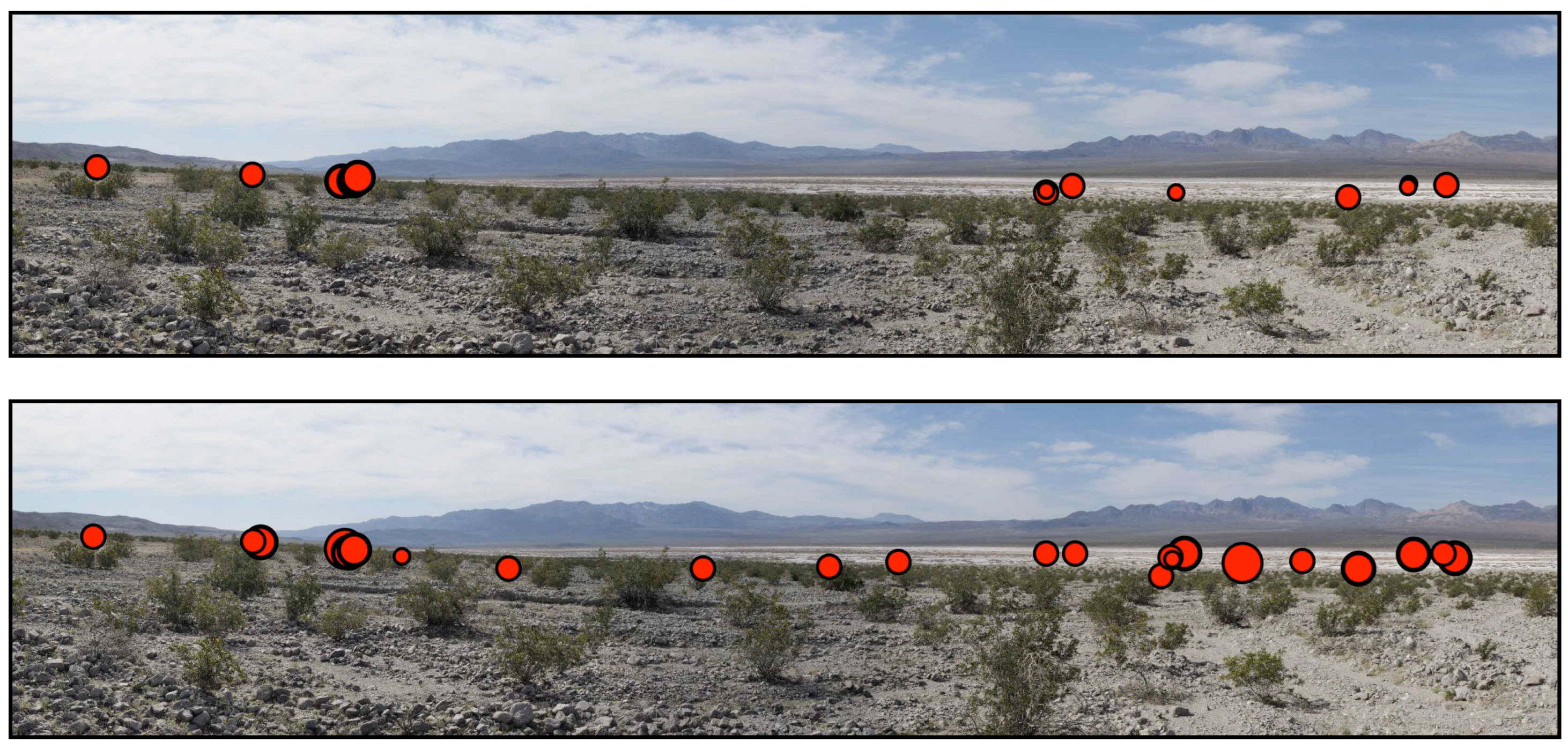
Figure 14 displays a horizon scan that occurred in the geology study. When our fixation finder did not use head motion compensation, it detected fewer fixations (Figure 14, top) than the same fixation-finder detected when head motion compensation was applied (Figure 14, bottom). Only with head motion compensation does the fixation pattern show that the observer scanned the horizon.
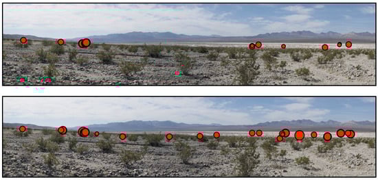
Figure 14.
Effect of head motion compensation during horizontal scan. In this example, the same 5 seconds of an observer scanning the horizon is plotted without (top) and with (bottom) head motion compensation. Fixations are plotted as red dots and longer fixations are plotted with a larger dot size. Without head motion compensation, 13 fixations totaling 2069 ms of looking time were captured. With head motion compensation, 23 fixations totaling 4638 ms of looking time were captured.
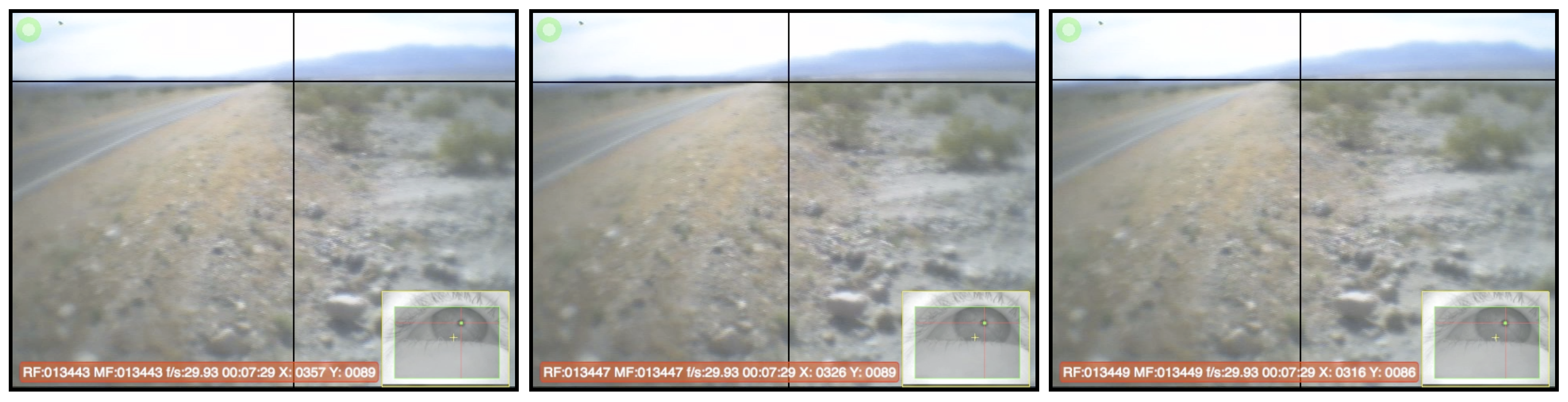
Head motion compensation does not always increase the number of fixations that are detected. An example of this is seen in Figure 15: these frames were taken from an eye-tracking video as an observer slowly turned her head to the right (thus the landscape features are moving farther to the left in these images), while maintaining gaze on a single spot (as indicated by the gaze crosshairs).
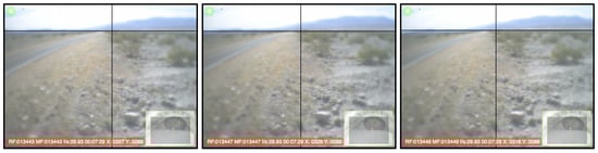
Figure 15.
Effect of head motion compensation during slow head rotation. Shown above are median frames from three separate fixations that were detected when head motion compensation was not applied; with head motion compensation, these were combined into a single fixation.
Without head motion compensation, our fixation finder detected three separate fixations (representative median frames are shown in Figure 15) lasting 100 ms, 133 ms, and 100 ms, respectively. With head motion compensation, our fixation finder detected one fixation of 333 ms, which encompassed all of the frames shown in Figure 15.
Head motion compensation can sometimes capture fixations that were otherwise not detected (Figure 14) and sometimes unite fixations that were otherwise divided (Figure 15). Regardless of the nature of the effect, applying head motion compensation to mobile eye-tracking studies allows a more accurate representation of when gaze is directed to a single area than a dispersion threshold alone. This correction is especially important when observers are surrounded by stimuli and therefore likely to make frequent head and body rotations in tandem with eye movements.
Fixation Detection Summary
The optimal fixation detection settings will partly depend on the hardware, and most eye-trackers will have a recommended setting. Note that in some cases, this limits the phenomena that can be captured, because the frame rates and accuracy of most mobile eye-trackers preclude detection of short fixations and small saccades. Additionally, if the system will be used outdoors, fixation detection and timing must be based only on pupil stability (with a threshold of either pupil position or point-ofregard based on pupil position alone). In studies where head and body movements are allowed, pupil stability is not sufficient to capture all instances of steady gaze: either head motion compensation is required, or the experimenters must acknowledge that some gaze is excluded from the detection procedure.
Analyzing Gaze from Eye-Tracking Videos
After a mobile eye-tracking video is fully calibrated and parsed into fixations, experimenters face the daunting task of determining what to do with the video data. Even basic eye movement statistics are different in mobile eyetracking. In addition to changing the definition of steady gaze, head movements cause saccade amplitude to be a less meaningful construct, because it ignores the effect of redirecting gaze through head movements. Saccade velocity also ignores head and body movements, but cannot even be tracked due to low frame rates. In indoor mobile eye-tracking studies, both the total number of fixations and the mean fixation duration can be reported; however, in outdoor recordings, only the mean fixation duration should be used because increased track loss in outdoor environments will reduce the number of fixations that can be detected, and the amount of track loss may be uneven across observers and experimental conditions.
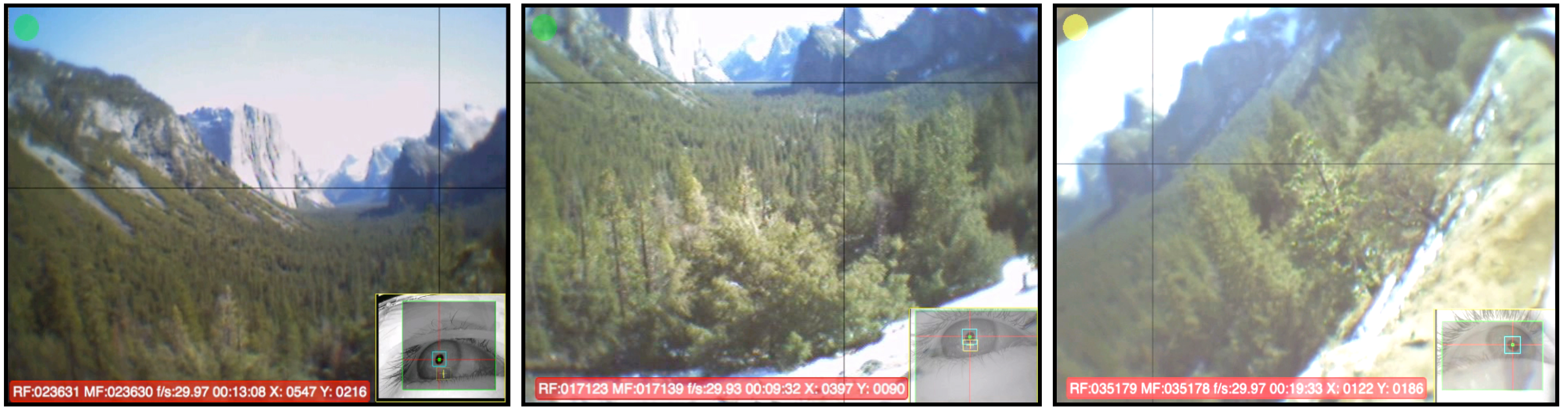
A common approach in both mobile and stationary eye-tracking analysis is to identify areas of interest (AOIs) in the scene (e.g., the large U-shaped valley and the smaller hanging valley in Figure 16 might be identified), and then compute outcome measures such as the proportion of fixations in a given AOI, the proportion of time in an AOI, transition probabilities between AOIs, earliest fixation in an AOI, etc. In stationary eye-tracking studies with static stimuli, AOIs can be drawn onto the image and then the location (in x,y screen coordinates) of the gaze crosshairs can be used to determine which AOI is being fixated. However, gaze estimates in mobile eyetracking studies are calculated in the scene camera space (x,y pixel coordinates) rather than stimulus space, and additional processing stages are needed in order to determine what object or area is being fixated. For example, the gaze crosshairs in Figure 16 have different coordinates even though the same part of stimulus area is being fixated. Early mobile eye-tracking studies labeled the AOI of each fixation manually, and now many mobile eye-tracker manufacturers offer an analysis tool to aid in this coding process. These tools differ in their implementation and therefore their appropriateness for specific applications and stimulus types, as discussed below.
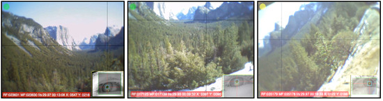
Figure 16.
Lack of correspondence between fixated object and its location in the scene video. In each of the above frames, the observer is fixating the same feature (a hanging valley), but head movements and the different positions of each observers cause the feature’s location in the scene video to vary.
Some systems (such as Tobii Technology’s Tobii Glasses) can be used with active infrared (IR) markers that are placed in the tracking environment to mark AOI boundaries. With this method, some spatial information about the location of fixations is preserved, so the output provides more knowledge than simply which AOI was fixated. The IR markers can be kept in the same position for different observers and are robust to observer movements, so the number of observers or length of recording does not add to the processing load. This method has been successfully used in a variety of applications, but the reliance on IR markers places some limitations on the types of scenes that can be analyzed. Most importantly, although observers can move around the scene, the AOIs and the IR markers must remain in a fixed position and must be visible in the scene camera (e.g., in Figure 16 the AOIs are located too far). Additionally, although the IR light is not visible to observers, the markers themselves are. Ouzts, Duchowski, Gomes, and Hurley (2012) reported that markers did not attract extra fixations when they were placed over projected supermarket shelves on a two-dimensional projection screen when observers had a relatively demanding search task. The authors of that study pointed out that further work is required to determine whether the same result would be found without the demanding task and/or in three-dimensional environments.
It is possible to define two-dimensional AOIs within a scene without the use of active IR markers. Simultaneous Localization and Mapping (SLAM) is a method developed for mobile robotics that allows a mobile camera to map a novel environment and to locate itself within that map. Some eye-tracking analysis software (e.g., Applied Science Laboratories’ GazeMap) uses a similar technique to map an environment and allow the user to identify two-dimensional AOIs within the map. Building the map requires recording a separate video that includes a reference target and all AOIs, then outlining and identifying the AOIs in the software. This tool can be used to train a large number of two-dimensional AOIs, and preserves spatial information about the location of fixations within the AOIs. However, if AOIs span significant depth, a single model cannot represent all perspectives and so observers’ positions must be restricted (e.g., in Figure 16, the position of foreground trees relative to background features is sharply influenced by the observer’s position, and so a single AOI map could not be used for different observer positions). It is therefore most useful with planar AOIs.
There are also tools that give each fixation an AOI code on the basis of image features extracted from the scene camera (e.g., Positive Science’s SemantiCode). In this method, fixations (or clusters of fixations with similar image properties) are identified, and users code the fixations with the desired AOI label. A database contain
ing each AOI’s image features is built using supervised machine-learning techniques so that after some training, fixations are evaluated against the database and the software suggests the best match. This tool is more userguided than the other methods, but the approach is also more flexible, being able to handle dynamic AOIs, AOIs at any distance, and any number of AOIs. However, because this tool relies on image features, AOIs that have very similar or even identical features can be confused, though it is generally able to learn even subtle differences (e.g., the differences between mountains in Figure 16). In this approach, each fixation is coded only according to its AOI label, so no information about spatial location is provided.
Another method, proposed by Brône, Oben, and Goedemé (2011), uses object-level recognition techniques to identify specific objects within an observer’s field of view. The system is trained with example photographs of the desired targets, then the region surrounding the fixation in each frame is analyzed. If a sufficiently strong match is found to a stored object (i.e., the match exceeds a given threshold), the fixated object is labeled. The system was shown to be efficient, using fast SURF feature matching (Bay, Ess, Tuytelaars, & Van Gool, 2008) and reducing the computational load by processing only the image region near fixation.
Eye, head, and gaze position information can all be extracted from the scene video. For example, Land and colleagues (e.g., Land et al., 1999; Land & Lee, 1994; Land & McLeod, 2000) have monitored head orientation by measuring the movement of fixed objects in the scene video, monitored eye-in-head orientation by measuring the movement of the gaze cursor, and combined the two signals in order to determine gaze angle. This approach is especially useful for dynamic scenes in which the relationship between gaze and a specific target (e.g., offset from the side of the road or an approaching cricket ball) is more meaningful than absolute spatial coordinates of gaze. If dynamic, the location of the target must also be tracked, which Land and colleagues have done by manually coding the video. This method relies on manual processing, but is manageable for small studies.
The tools described above can greatly simplify mobile eye-tracking analysis, but are all limited to AOI-based analyses. For studies such as the geology project, precise spatial information of fixations within AOIs (e.g., whether observers trace the border of a mountaintop) is desirable, but there is no automated solution that can track spatial location and hand distant, three-dimensional AOIs. Currently, we manually plot each subject’s fixations onto a two-dimensional high-resolution panorama of each scene. This allows us to examine fixations in a stimulus-based coordinate space that is common across all observers and across time, but introduces both human error and a sizeable processing bottleneck. We are developing a tool to plot fixations automatically, by matching the central frame from each fixation onto the highresolution panorama, and then transferring the fixation’s position from scene video coordinates to the panorama’s coordinates.
Analysis Summary
The options for analyzing mobile eye-tracking data have greatly improved in recent years. Each tool has its own advantages and limitations, and the appropriateness depends on the intended applications. Currently, analysis options are tied to the tracking unit that is used, and so this decision should be considered when selecting a tracking unit. The options are likely to continue evolving, but the general issues to consider are whether the intended experiments will require spatial analysis of fixations, dynamic AOIs, target-relative gaze, or observer movements. Beyond these requirements, it is worth considering time-saving factors, such as the ease of set-up, simplicity of adding observers, operator involvement, ability to add new AOIs after the recording is finished, and compatibility with statistics packages.
Conclusions
As the technology and tools available to eye-tracking researchers have advanced, limits on the tasks and environments that can be explored have virtually disappeared. For our recent work, this freedom has allowed us to examine the visual processing of novice and expert geologists as they view complex natural scenes. The opportunity to collect data away from the laboratory and in remote locations affords special insight into learning processes, because a novice geologist’s first field study is a pivotal experience in comprehending geodynamics. It is important both for researchers to realize how the use of these tools differs from stationary eye-tracking techniques and for eye-tracking developers to realize the barriers that still exist and that should be addressed.
We have found that all stages of processing eyetracking data must be tailored to the specific conditions in which the data are collected. The best way to calibrate the eye-tracker will depend on stimulus characteristics during the experiment (i.e., the distance to fixated objects and what eccentricity of eye movements is expected), and the number of calibration sessions should increase with the duration and physical intensity of the tracking session. The ability to track the pupil and corneal reflection with currently existing automated methods will depend on the tracking environment, as both signals are difficult to track outdoors. Together, the tracking environment and stimulus locations have strong implications for the appropriate method of detecting fixations, because unstable corneal reflection tracks and frequent head movements complicate standard methods of detecting steady gaze. Finally, comparing fixations across time and observers requires special tools which are still limited.
The method we have developed is sufficient to collect and analyze outdoor mobile eye-tracking data, but we expect—and hope—that the procedures will become more streamlined and automated. For example, we currently use a method of pupil detection that combines some advanced pupil detection settings (i.e., the ability to restrict search areas) with manual intervention. We are working on improved automated algorithms that can detect the pupil and corneal reflection centroids even in the presence of bright light and non-canonical pupil shapes, and hope that our tool and others will soon be available. Because accurate pupil and corneal reflection detection is so critical to successful data collection, and because our current method is time-consuming and introduces the possibility for human error, development of a stable automated alternative that can handle outdoor videos is a high priority.
Our method of detecting steady gaze is currently automated, but requires input from multiple sources that operate in isolation from other stages in the data processing framework. We quantify scene motion through a MATLAB script whose output is read by our in-house fixation detector. To address the increased noise associated with tracking the corneal reflection, we calibrate one video without the corneal reflection (and use this video to define fixations temporally) and calibrate another video with the P-CR signal (used to define fixations spatially). Our fixation detector first reads the pupil-only file and generates an output file with fixation timing information; this file is then loaded along with the P-CR data, in order to locate fixations. This kluge is time-consuming and cannot easily be adopted by other platforms. As the need for motion compensation and the problems associated with mixing pupil-only and P-CR observers become better known, it is likely that manufacturers will integrate similar solutions into their processing software, thus reducing the manual workload.
Tools for comparing mobile eye-tracking data across time and observers are also likely to see some improvements. The existing methods all work very well for specific types of recording environments and research questions, but studies such as the geology project reveal a need for additional tools. The automated and user-guided AOI coding tools we reviewed expand upon early manual coding methods. Similarly, our current manual plotting approach is leading to an automated solution, though this is still under development as we address some challenges with natural scenes.
The young field of mobile eye-tracking has already revealed key insights to visual processing during the performance of skilled tasks such as sports, driving, and food preparation (reviewed in Land, 2006). The process of learning these skills was previously hard to examine, both because of difficulty tracking in environments outside the laboratory, and limitations on how much data can be collected and analyzed. The recommendations presented here provide a guide for overcoming these traditional limitations and for developing new tools that better facilitate data collection and analysis.
Acknowledgements
This work is supported by NSF 0909588.
References
- Babcock, J. S., and J. B. Pelz. 2004. Building a lightweight eyetracking headgear. In Proceedings of the ACM SIGCHI: Eye Tracking Research and Applications symposium; pp. 109–114. [Google Scholar]
- Bay, H., A. Ess, T. Tuytelaars, and L. Van Gool. 2008. SURF: Speeded up robust features. Computer Vision and Image Understanding 110, 346–359. [Google Scholar] [CrossRef]
- Brône, G., B. Oben, and T. Goedemé. 2011. Towards a more effective method for analyzing mobile eyetracking data: integrating gaze data with object recognition algorithms. In Proceedings of the 1st international workshop on pervasive eye tracking & mobile eye-based interaction (PETMEI '11); pp. 53–56. [Google Scholar]
- Cerrolaza, J., A. Villanueva, M. Villanueva, and R. Cabeza. 2012. Error characterization and compensation in eye tracking systems. In Proceedings of the ACM SIGCHI: Eye Tracking Research and Applications symposium; pp. 205–208. [Google Scholar]
- Charness, N., E. M. Reingold, M. Pomplun, and D. M. Stampe. 2001. The perceptual aspect of skilled performance in chess: Evidence from eye movements. Memory & Cognition 29, 8: 1146–1152. [Google Scholar]
- Duchowski, A. T. 2003. Eye tracking methodology: Theory and practice. Berlin: Springer. [Google Scholar]
- Fadaeieslam, M. J., M. Soryani, and M. Fathy. 2011. Efficient key frames selection for panorama generation from video. Journal of Electronic Imaging 20, 2: 023015. [Google Scholar] [CrossRef]
- Fischler, M. A., and R. C. Bolles. 1981. Random sample consensus: a paradigm for model fitting with applications to image analysis and automated cartography. Communications of the ACM, vol. 24, pp. 381–395. [Google Scholar]
- Hayhoe, M., and D. Ballard. 1995. Eye movements in natural behavior. TRENDS in Cognitive Sciences 9, 4: 188–194. [Google Scholar] [CrossRef]
- Holmqvist, K., M. Nystrom, R. Andersson, R. Dewhurst, H. Jarodzka, and J. van de Weijer, eds. 2011. Eye tracking: A comprehensive guide to methods and measures. Oxford, UK: Oxford University Press. [Google Scholar]
- Irwin, D. E., and L. A. Carlson-Radvansky. 1996. Cognitive suppression during saccadic eye movements. Psychological Science 7, 2: 83–88. [Google Scholar] [CrossRef]
- Kinsman, T., K. Evans, G. Sweeney, T. Keane, and J. Pelz. 2012. Ego-motion compensation improves fixation detection in wearable eye tracking. In Proceedings of the ACM SIGCHI: Eye Tracking Research and Applications symposium; pp. 221–224. [Google Scholar]
- Krupinski, E. A., A. A. Tillack, L. Richter, J. T. Henderson, A. K. Bhattacharyya, K. M. Scott, and R. S. Weinstein. 2006. Eye-movement study and human performance using telepathology virtual slides. Implications for medical education and differences with experience. Human Pathology 37, 1543–1556. [Google Scholar]
- Land, M. F. 2006. Eye movements and the control of actions in everyday life. Progress in Retinal and Eye Research 25: 296–324. [Google Scholar] [PubMed]
- Land, M. F., and D. Lee. 1994. Where we look when we steer. Nature 369, 742–744. [Google Scholar]
- Land, M. F., and P. McLeod. 2000. From eye movements to actions: how batsmen hit the ball. Nature Neuroscience 3, 1340–1345. [Google Scholar] [CrossRef] [PubMed]
- Land, M. F., N. Mennie, and J. Rusted. 1999. The roles of vision and eye movements in the control of activities of daily living. Perception 28, 1311–1328. [Google Scholar] [CrossRef] [PubMed]
- Land, M. F., and B. Tatler. 2009. Looking and acting: Vision and eye movements in natural behaviour. Oxford: Oxford University Press. [Google Scholar]
- Li, F., S. Munn, and J. B. Pelz. 2008. A model-based approach to video eye tracking. Journal of Modern Optics 55, 4: 503–531. [Google Scholar] [CrossRef]
- Lowe, D.G. 2004. Distinctive image features from scale invariant keypoints. International Journal of Computer Vision 60, 2: 91–110. [Google Scholar] [CrossRef]
- Matin, E. 1974. Saccadic suppression: A review. Psychological Bulletin 81, 899–917. [Google Scholar] [CrossRef]
- Nodine, C. F., and H. L. Kundel. 1987. Using eye movements to study visual search and to improve tumor detection. RadioGraphics 7, 6: 1241–1250. [Google Scholar] [PubMed]
- Ouzts, A. D., A. T. Duchowski, T. Gomes, and R. A. Hurley. 2012. On the conspicuity of 3-D fiducial markers in 2-D projected environments. In Proceedings of the ACM SIGCHI: Eye Tracking Research and Applications symposium; pp. 325–328. [Google Scholar]
- Pelz, J. B., T. B. Kinsman, and K. M. Evans. 2011. Analyzing complex gaze behavior in the natural world. In Proceedings of SPIE: The International Society for Optical Engineering; p. 7865. [Google Scholar]
- Raab, D. H. 1963. Backward Masking. Psychological Bulletin 60, 2: 118–129. [Google Scholar] [PubMed]
- Salvucci, D. D., and J. H. Goldberg. 2000. Identifying fixations and saccades in eye-tracking protocols. In Proceedings of the Eye Tracking Research and Applications Symposium; pp. 71–78. [Google Scholar]
- Thrun, S. 2008. Simultaneous Localization and Mapping. In Robot and Cognitive Approaches to Spatial Mapping, Springer Tracts in Advanced Robotics. Edited by M. E. Jeffries and W. Yeap. Springer: Berlin: Vol. 38, pp. 13–41. [Google Scholar]
- Wyatt, H. J. 2010. The human pupil and the use of video-based eyetrackers. Vision Research 50, 19: 1982–1988. [Google Scholar] [CrossRef] [PubMed]


© 2012 by the authors. This article is licensed under a Creative Commons Attribution 4.0 International License.