Elevation of the first metatarsal is frequently assessed by means of lateral radiographs of the foot. This condition typically is evaluated subjectively; that is, superimposition of the distal segments of the first and second metatarsals is considered normal, and metatarsus primus elevatus is suspected if the superior aspect of the first metatarsal distal segment is positioned above the second metatarsal.
Elevation of the first metatarsal is frequently mentioned in discussions of function at the first metatarsophalangeal joint. Lambrinudi[
1] used the term “metatarsus primus elevatus” as early as 1938; he described it as an anatomical variation in which the plane of the first metatarsal lies above the plane of the lesser metatarsals. Root et al[
2] list metatarsus primus elevatus as an etiology of hallux limitus and hallux rigidus. Other authors have also referred to the condition when evaluating hallux abducto valgus deformity and hallux limitus, both preoperatively[
3-
5] and postoperatively.[
6]
An objective means of measuring metatarsus primus elevatus is seldom used. Schuberth et al[
7] evaluated metatarsus primus elevatus by comparing the declination of the first and second metatarsals after drawing tangents to their dorsal diaphyseal cortices (called the “sagittal intermetatarsal angle”). Meyer et al[
8] analyzed this relationship by radiographically measuring the distance between the first and second metatarsals at the distal metaphyseal flare (from a line drawn perpendicular to the plane of support) of the first metatarsal. However, to the authors’ knowledge, neither of these measurement techniques has been validated scientifically as to its reproducibility or reliability. Seiberg et al[
9] also noted that there is no single accurate measurement technique to determine first metatarsal elevation.
Positioning of the foot in the angle and base of gait is critical for assessing the relationship between the first and second metatarsals. A foot that is inadvertently inverted or supinated can grossly affect the position of the first metatarsal relative to the second. However, other factors—such as x-ray tube head position and angulation[
10] and direction of the central x-ray beam—may also contribute to the radiographic picture of metatarsus primus elevatus, even if the foot and film are positioned properly.
The standard weightbearing lateral radiograph of the foot is obtained such that the central ray is perpendicular to the x-ray film and cassette combination and directed at the cuboid. Unfortunately, there may be limitations imposed by the x-ray machine and how the image is formed. For example, the device that indicates numerical tube-head angulation is not always accurate; if the angle indicator is spun in a random trial, one will notice that it does not always point to the same angular measurement because of surface friction. Additionally, only 5° increments are marked by this indicator.
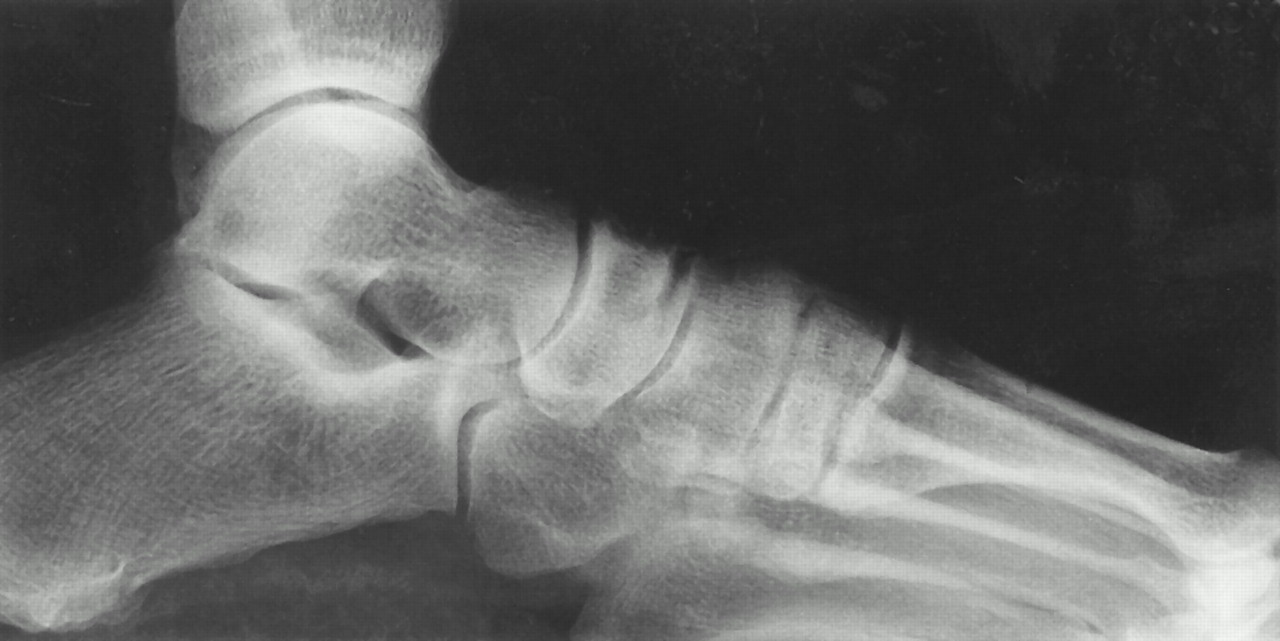
The geometry of image formation is easily ignored but plays a significant role in image interpretation. For example, it is not uncommon to see that the fifth metatarsal head is partially cut off of the film by the lead lining of the orthoposer in the weightbearing lateral view (
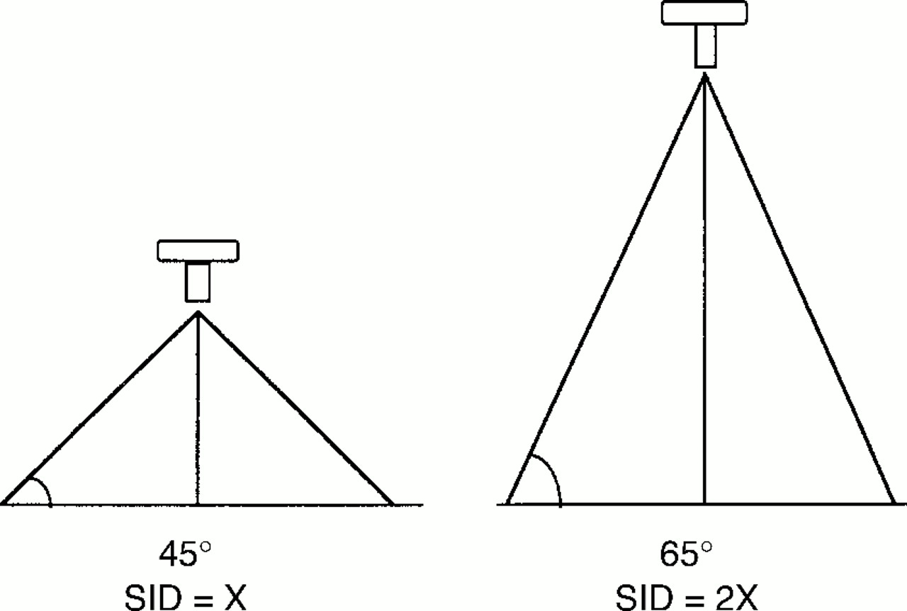
Fig. 1). This occurs because the x-ray beam is divergent: as the x-rays exit the fifth metatarsal head, they continue downward toward the orthoposer. To counter this effect, it may be necessary to raise the foot above the orthoposer surface by having the patient stand on a cork or felt pad. Furthermore, different brands of lower-extremity–specific x-ray units have different source-to-image distances (21 and 28 inches). Greater x-ray beam divergence, resulting in size distortion of the image, will occur at a shorter source-to-image distance (
Fig. 2).[
11,
12]
Figure 1.
The fifth metatarsal head is not visible because it is superimposed by the orthoposer’s lead sheet.
Figure 1.
The fifth metatarsal head is not visible because it is superimposed by the orthoposer’s lead sheet.
Figure 2.
A shorter source-to-image distance (SID) results in greater x-ray beam divergence.
Figure 2.
A shorter source-to-image distance (SID) results in greater x-ray beam divergence.
Additionally, the central ray light indicator is not sharply visible on the foot and the cuboid is not plainly visible through the skin; the central ray could subsequently be directed not at the cuboid, but either superior, inferior, anterior, or posterior to it.
The purpose of this preliminary study was twofold: 1) to determine whether tube-head angulation or central ray direction can influence the positional relationship between the first and second metatarsals in the weightbearing lateral foot radiographic view, and 2) to investigate the use of a potentially reproducible measuring technique to detect first metatarsal elevation.
Materials and Methods
Apparatus
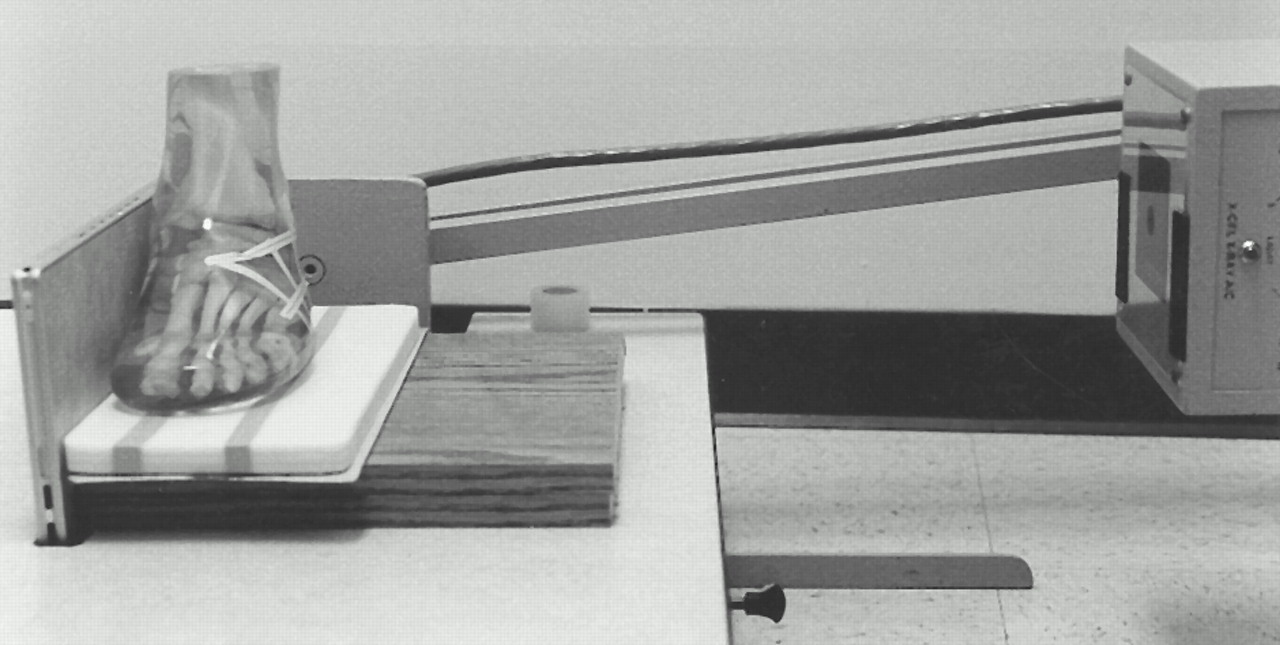
Lateral radiographs of a foot phantom were obtained using a weightbearing x-ray unit dedicated to performing foot and ankle studies (X-Cel X-Ray Corp, Crystal Lake, Illinois). A DuPont Cronex cassette was used with two Quantex Detail intensifying screens (DuPont Medical Products, Wilmington, Delaware); and Sterling Cronex 10T film (Sterling Diagnostics Imaging, Inc, Newark, Delaware) was used. The film and cassette were placed vertically in the orthoposer slot. A raised platform was placed on the orthoposer to allow greater flexibility with the radiographic technique (ie, tube-head position); this platform was covered with a vinyl-coated sheet of lead, and an additional ⅝-inch slab of radiolucent, high-durometer polyethylene foam was placed over the lead sheet so that the position of the fifth metatarsal head could also be visualized in the radiograph (
Fig. 3). The plantar surface of the phantom was positioned on the foam so that the medial aspect of the foot was against and the midline of the foot parallel to the cassette. All other technical factors (kilovolts [peak], milliamperes, source-to-image distance, film and screen type, and processing) remained constant for all radiographs. The foot phantom was never moved; only the cassette was removed and replaced after it was loaded with new film. The useful x-ray beam was collimated to encompass the entire foot and ankle, as is customary for the standard weightbearing lateral foot view.
Figure 3.
The apparatus used to obtain radiographs in this study.
Figure 3.
The apparatus used to obtain radiographs in this study.
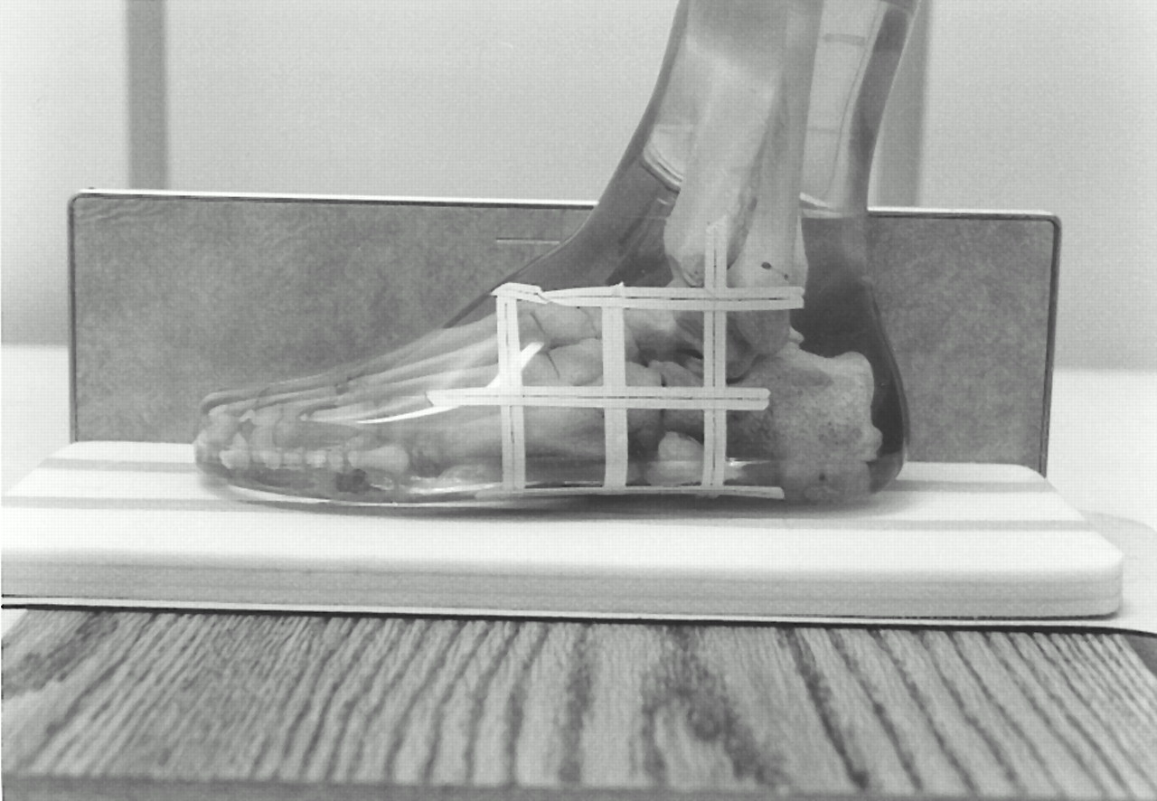
The only factors manipulated in the procedure were the tube-head angle and the central beam direction. A 3 × 3-cm translucent grid, positioned in the sagittal plane, was transposed onto the phantom so that one grid intersection was positioned directly over the cuboid, at the level of the cuboid–lateral cuneiform articulation. This intersection was used as the reference for all other points. The grid was then marked on the phantom with radiolucent tape (
Fig. 4). The horizontal lines were parallel and the vertical lines were perpendicular to the plane of support. The resultant grid was composed of nine points at the intersections of three vertical and three horizontal lines. The 3 × 3-cm grid was chosen because it allowed greater precision when positioning the tube head and directing the central beam. The nine points or intersections were labeled as shown in
Figure 5. Three radiographs were obtained with the central beam directed at each of the nine specific points marked on the phantom at the following tube-head angulations (from vertical): 80°, 85°, and 90°. In order to reduce the surface friction of the lightweight needle angle indicator that was affixed to the tube head by the manufacturer and, subsequently, to improve its accuracy, a 1-ounce lead weight was suspended from the indicator needle with approximately 12 inches of fine nylon monofilament thread.
Figure 4.
The foot phantom is shown with the transposed 3 × 3-cm grid.
Figure 4.
The foot phantom is shown with the transposed 3 × 3-cm grid.
Figure 5.
The labeled grid intersections that were determined by the direction of the central beam. The central beam is normally aimed at the cuboid (position CC, central cuboid); all other points are named based on the direction of the central beam relative to position CC at 3-cm increments. Abbreviations: AS, anterosuperior; CS, centrosuperior; PS, posterosuperior; AC, anterocentral; PC, posterocentral; AI, anteroinferior; CI, centroinferior; PI, posteroinferior.
Figure 5.
The labeled grid intersections that were determined by the direction of the central beam. The central beam is normally aimed at the cuboid (position CC, central cuboid); all other points are named based on the direction of the central beam relative to position CC at 3-cm increments. Abbreviations: AS, anterosuperior; CS, centrosuperior; PS, posterosuperior; AC, anterocentral; PC, posterocentral; AI, anteroinferior; CI, centroinferior; PI, posteroinferior.
Measurement Technique
A graticule system was used to obtain measurements on each radiograph. It consisted of a baseline and a line perpendicular to that baseline, generated with a computer-assisted design (CAD) system. The graticule was printed on a clear acetate sheet and was placed over the radiograph. The baseline of the graticule was aligned with the lead-lined weightbearing surface that was clearly visible in the radiograph. The acetate sheet was further manipulated so that the perpendicular line passed through the dorsal-most point of the first metatarsal head, corresponding to the junction of the apparent articular surface and the metaphyseal flare. The point of intersection of the perpendicular line and the second metatarsal was identified. A digital vernier caliper was used to measure, in millimeters, the distance along the perpendicular line between the intersection of that line and the dorsal aspects of the first and second metatarsals.
The authors also wanted to test the reproducibility and reliability of the measurement technique for the foot phantom radiographs for one measurer (C.C.S.). The 27 radiographs were evaluated in random order. After all 27 radiographs had been evaluated, 10 radiographs were selected at random and evaluated a second time. Then these same ten radiographs were evaluated a third time in random order.
Results
Table 1 lists the measurements obtained on all radiographs.
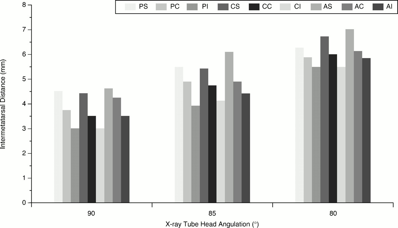
Figure 6 graphically charts the results from all 27 radiographs, grouped by tube-head angulation and split by central beam direction.
Figures 7 through
[
9]are selected examples from the sample.
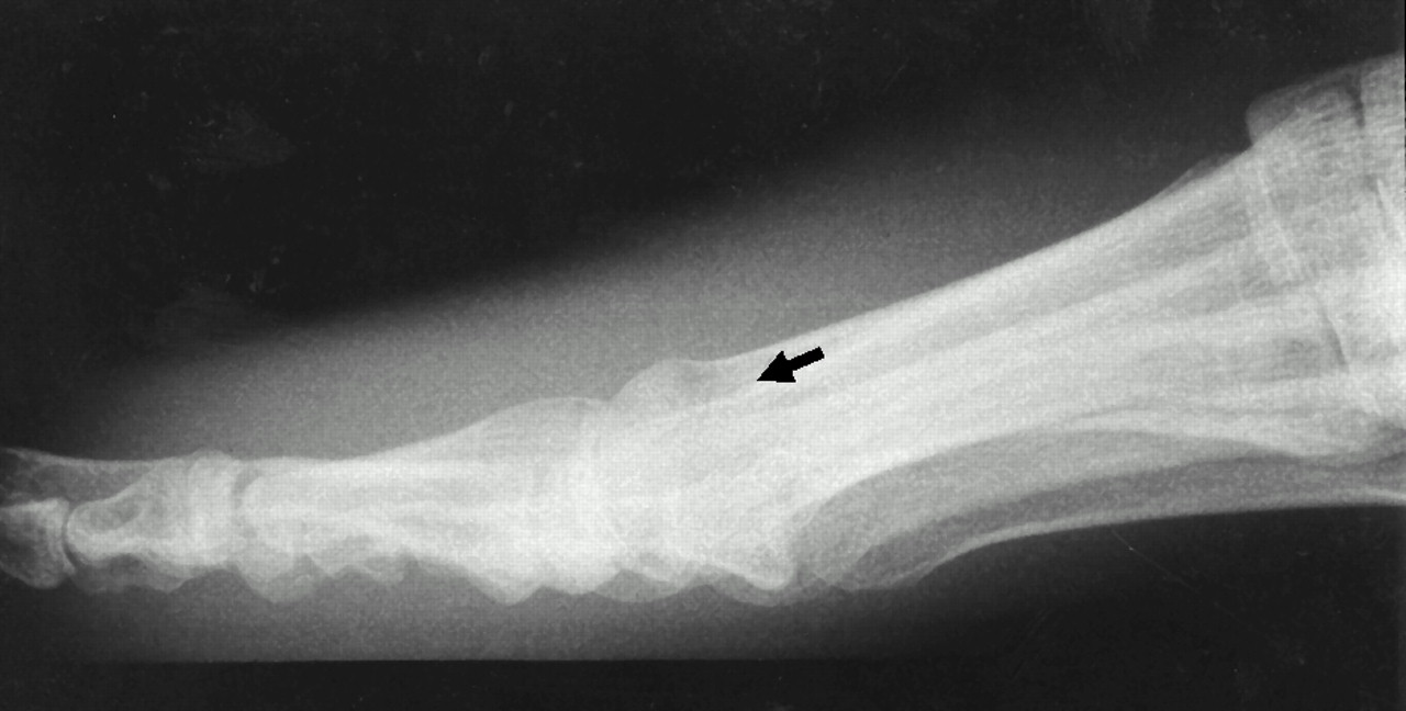
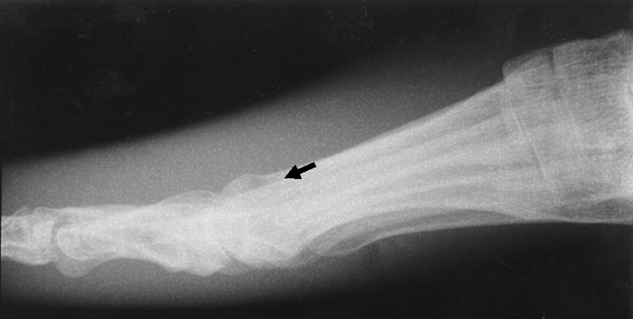
Figure 7 represents a true lateral radiograph with tube-head angulation at 90° and central beam directed at the cuboid–lateral cuneiform articulation, the point of reference. The elevation measured on this view is 3.66 mm.
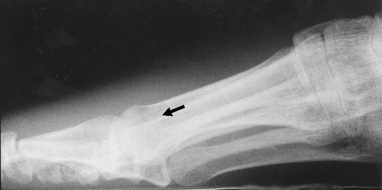
Figure 8 illustrates an 80° lateral view with the central beam directed at the lateral cuneiform–cuboid articulation. Elevation on this view was measured at 6.09 mm.
Figure 9 illustrates a 90° lateral radiograph with the central beam directed at a point 3 cm superior to the point of reference. The elevation measured on this view is 4.41 mm.
Figure 6.
Histogram of results from the study. Note that, although only one specimen was used, the measurements suggest that the distance between the first and second metatarsals varies consistently with tube-head angulation and central x-ray beam direction. Abbreviations: PS, posterosuperior; PC, posterocentral; PI, posteroinferior; CS, centrosuperior; CC, central cuboid; CI, centroinferior; AS, anterosuperior; AC, anterocentral; AI, anteroinferior.
Figure 6.
Histogram of results from the study. Note that, although only one specimen was used, the measurements suggest that the distance between the first and second metatarsals varies consistently with tube-head angulation and central x-ray beam direction. Abbreviations: PS, posterosuperior; PC, posterocentral; PI, posteroinferior; CS, centrosuperior; CC, central cuboid; CI, centroinferior; AS, anterosuperior; AC, anterocentral; AI, anteroinferior.
Figure 7.
The tube-head angulation is at 90° and the central beam is directed at the cuboid–lateral cuneiform articulation. The arrow indicates the distal aspect of the second metatarsal.
Figure 7.
The tube-head angulation is at 90° and the central beam is directed at the cuboid–lateral cuneiform articulation. The arrow indicates the distal aspect of the second metatarsal.
Figure 8.
The tube-head angulation is at 80° and the central beam is directed at the cuboid–lateral cuneiform articulation. The arrow indicates the distal aspect of the second metatarsal.
Figure 8.
The tube-head angulation is at 80° and the central beam is directed at the cuboid–lateral cuneiform articulation. The arrow indicates the distal aspect of the second metatarsal.
Figure 9.
The tube-head angulation is at 90° and the central beam is directed 3 cm superior to the cuboid–lateral cuneiform articulation. The arrow indicates the distal aspect of the second metatarsal.
Figure 9.
The tube-head angulation is at 90° and the central beam is directed 3 cm superior to the cuboid–lateral cuneiform articulation. The arrow indicates the distal aspect of the second metatarsal.
Table 1.
Measurements Obtained Using the Graticule Measuring Technique
Table 1.
Measurements Obtained Using the Graticule Measuring Technique
Discussion
The data in
Table 1 demonstrate that, in all cases with the central x-ray beam direction remaining constant, there is an increased distance between the first and second metatarsal heads with decreasing angulation of the x-ray tube head from the vertical position. Furthermore, the data indicate that, in all cases with the tube-head angulation remaining constant, there is an increased distance when the central x-ray beam is directed more superiorly. These findings relate directly to the geometric formation of the film image.
Other factors that were not addressed in this project, but that could influence the appearance of metatarsus primus elevatus on a radiograph, include variations in the foot itself.[
13] For example, foot type (pes cavus
versus pes planus) and positioning of the foot relative to the film (pronated
versus supinated) can directly influence the geometric formation of the image. Another example is metatarsal lengths and their relationships to one another, which needs further investigation.
The phantom was used in this project simply to represent the osseous relationships of the foot bones and to eliminate the variability of foot position. Obviously, the phantom does not represent any specific biomechanical relationships in the human foot.
Analysis of the descriptive data in
Table 1 and examination of the chart in
Figure 6 strongly suggest that the measurement technique used in this preliminary study is reliable and reproducible, at least for the foot phantom and the rater. Although intrarater reliability was not tested on other subjects (and, therefore, comparative statistics could not be obtained), the authors believe that this measurement technique would be reliable and reproducible in other subjects. Interrater reliability was also not tested in this study.
It is important to understand the technicality involved in obtaining lateral radiographic views. Attention must be paid to the precision of tube-head angulation and central beam direction. Also, one must question the accuracy of the angle indicators inherent to the x-ray machine itself.
Summary
There is little doubt regarding the existence and clinical significance of metatarsus primus elevatus; however, caution must be exercised when assessing the condition by means of lateral radiographs alone. The authors produced an apparent metatarsus primus elevatus in the same foot specimen by altering tube-head angulation and central beam direction. If positioning technique is strictly standardized, the graticule device used in this preliminary study may prove to be a reliable measuring technique to detect this condition.