Article

Processing Route Optimization and Characterization of Al6063–SiCp Metal-Matrix Composite Sheets

1
Institute of Metallurgy, Clausthal University of Technology, 38678 Clausthal-Zellerfeld, Germany
2
Faculty of Engineering, Ain Shams University, Cairo 11517, Egypt
3
Institute of Tribology and Energy Conversion Machinery, Clausthal University of Technology, 38678 Clausthal-Zellerfeld, Germany
*
Author to whom correspondence should be addressed.
Metals 2022, 12(4), 536; https://doi.org/10.3390/met12040536
Submission received: 4 February 2022 / Revised: 17 March 2022 / Accepted: 19 March 2022 / Published: 22 March 2022
(This article belongs to the Special Issue Alloy and Process Design of Metallic Materials)

Abstract

:
The target of this study is to develop routes for processing Al–SiCp (SiC particulate) sheets with improved microstructures; namely, the uniform distribution of SiCp and minimized porosity throughout the whole material, thereby improving its mechanical properties. Al–SiCp composites reinforced with 5, 10, and 15 vol.% SiC and having three average sizes of 29, 17, and 8.5 µm were produced using a semi-automated stir-casting machine; finally, the bars were hot rolled to get the final sheet dimensions. The rolling steps were performed based on the results of thermomechanical simulations performed on the cast blocks. The first rolling steps were applied according to a safe rolling schedule to avoid cracking via encouraging dynamic recrystallization. The last rolling steps were performed to improve the hardness and strength of the metal matrix composites (MMCs). A refinement in grain size from an average of 420 µm in the as-cast condition to an average of about 85 µm after rolling was observed. Some heterogeneity in grain size was observed where the regions with larger, elongated grains were associated with the zones depleted by SiCp reinforcement. Reinforcing with SiCp led to a small increase in tensile strength of 10–20 MPa, and this was further improved to about 60 MPa and 110 MPa for the 5 and 10 vol.% SiCp conditions, respectively, after a T6 heat treatment.

1. Introduction

Aluminum–ceramic-particulate metal-matrix composites (MMCs) such as Al–SiC particulate composites (Al–SiCp) are light weight, advanced constructional materials that are currently on the way to replace other conventional materials in many fields, such as their use in aerospace, automotive, and marine applications. The wide set of attractive properties offered by such composites is the reason for their demand in many applications. Some of these property combinations include high specific strength, high thermal resistance, and low coefficients of thermal expansion. The latter property is of particular importance for aeronautical and aerospace applications because it facilitates maintaining the vehicles’ components within the allowable temperature limits in the thermal environments to which they may be exposed [1]. The lower density of Al–SiCp, in comparison with monolithic Al alloys, provides them with high specific strength and stiffness modulus [2]. Further property combinations of Al–SiCp are good damping capacities, superior wear resistance, and satisfactory levels of corrosion resistance [3]. The general merits of using ceramic particulates as reinforcement in Al matrix are their isotropic nature and that they can be subjected to a variety of secondary forming operations, including extrusion, rolling, and forging [4]. The manufacturing method for Al–SiCp is a crucial factor as it dictates the properties and marks out the final costs. In this respect, several routes exist for the manufacturing of Al–SiCp, namely solid-, semisolid-, and liquid-state processes. While solid-state processes such as powder metallurgy yield higher mechanical properties, stir casting offers the advantage of being the most economically feasible [5]. In the context of mixing liquid–solid particles, turbulent mixing is more efficient for achieving homogeneous particle distribution than is laminar flow [6]. In turbulent flow, the fluid undergoes irregular fluctuations, whereas the fluid in laminar flow moves in smooth paths or layers. Determination of the best geometry for a specific mixing process requires a great deal of experimentation. In spite of understanding its physical and chemical mixing and casting behavior due to the work of several long-time investigators, a processing technology achieving optimized conditions and sequences is still lacking. The concern here is with the influence of turbulence on the spreading and mixing of particles. Despite the extensive experimentation for determining the parameters of efficient mixing, stir casting still suffers from a number of drawbacks, namely the tendency of particles to agglomerate, which creates voids, poor particle-matrix interfaces, the presence of porosity, and reinforces the settlement or floating of particles while the melt is solidifying [7,8]. Due to these microstructure defects, the Al–SiCp produced via stir casting suffers from low fracture toughness and ductility due to the ease of crack initiation at the interfaces between the ceramic particles and the matrix and at cast-porosities. Applying post-forming processes such as extrusion and forging is an effective means to counteract the aforementioned defects associated with stir casting [9,10]. In this respect, the proper design of both casting and rolling procedures results in achieving the desirable product properties [9,11] and proceeded cold rolling for stir-cast Al6063-SiCp specimens with SiCp volume percentages of 6 and 9%. The work reported a drop in the percentage of porosity associated with increasing the deformation during cold working, resulting in improvement in both SiC dispersion and material strength. Similar findings were reported by [12]; the effect of the reinforcement percentage and cold working on the precipitation of intermetallic phases was also reported in the same study. [9,13] demonstrated the applicability of hot rolling as a means to improve the microstructure of stir cast Al–SiCp MMCs, namely casting porosity, agglomeration, and particle matrix interface. Up to 98% rolling reduction was applied to Al 6061, 6082, and 7108 reinforced with 0–20% SiCp. Thermomechanical experiments were conducted to ascertain the optimum processing conditions. Successively, the authors studied the tensile behavior of hot-rolled samples before and after precipitation-hardening T6 heat treatments and in annealed conditions [13]. Generally, such rolled Al–SiCp sheet metals can find applications in the automobile industry as hanging panels and as chassis parts (seam-welded tubes), extrusions in bumper beams and crash boxes, in space frames, and where straight (or bended) profiles are needed [3].
The aim of this study is the development of a complete processing route for the production of Al–SiCp sheets via a combination of stir casting and hot rolling, yielding improved SiCp dispersion, minimized porosity, and consequently improved mechanical properties. Thermomechanical testing is used as a tool to simulate the rolling deformation of the composites for defining the rolling parameters. The tensile behaviors of hot-rolled samples, both in the as-rolled condition and after precipitation hardening with T6 heat treatment, are compared.

2. Materials and Methods

2.1. Materials Selection and Preparation

Commercial grade Al6063 (Trimet Aluminium AG, Essen, Germany) precipitation-hardened aluminum alloy, containing magnesium and silicon as its major alloying elements was selected for this study. The nominal range of Mg in this grade is from 0.45 to 0.90 as given by the DIN-Standard DIN EN 573-3, which is essential for improving the wetting between the SiC particles and the Al matrix. Another reason for selecting A16063 as the composite matrix is its high formability as it represents the main extrusion Al alloy, which allows complex shapes to be formed. Al6063 is widely used in architectural applications and is therefore often referred to as architectural aluminum. For reinforcement, different SiC-powder sizes, namely, F350 (27–31 µm), F500 (15–18 µm), and F800 (7–10 µm) were used. As the first step to improve the wetting between the particles and the Al matrix, the SiC powder was heated at 1100 °C for 4 h before its introduction into the melt. This treatment oxidizes the surface of the SiC particles and improves the particle matrix interface accordingly [14].

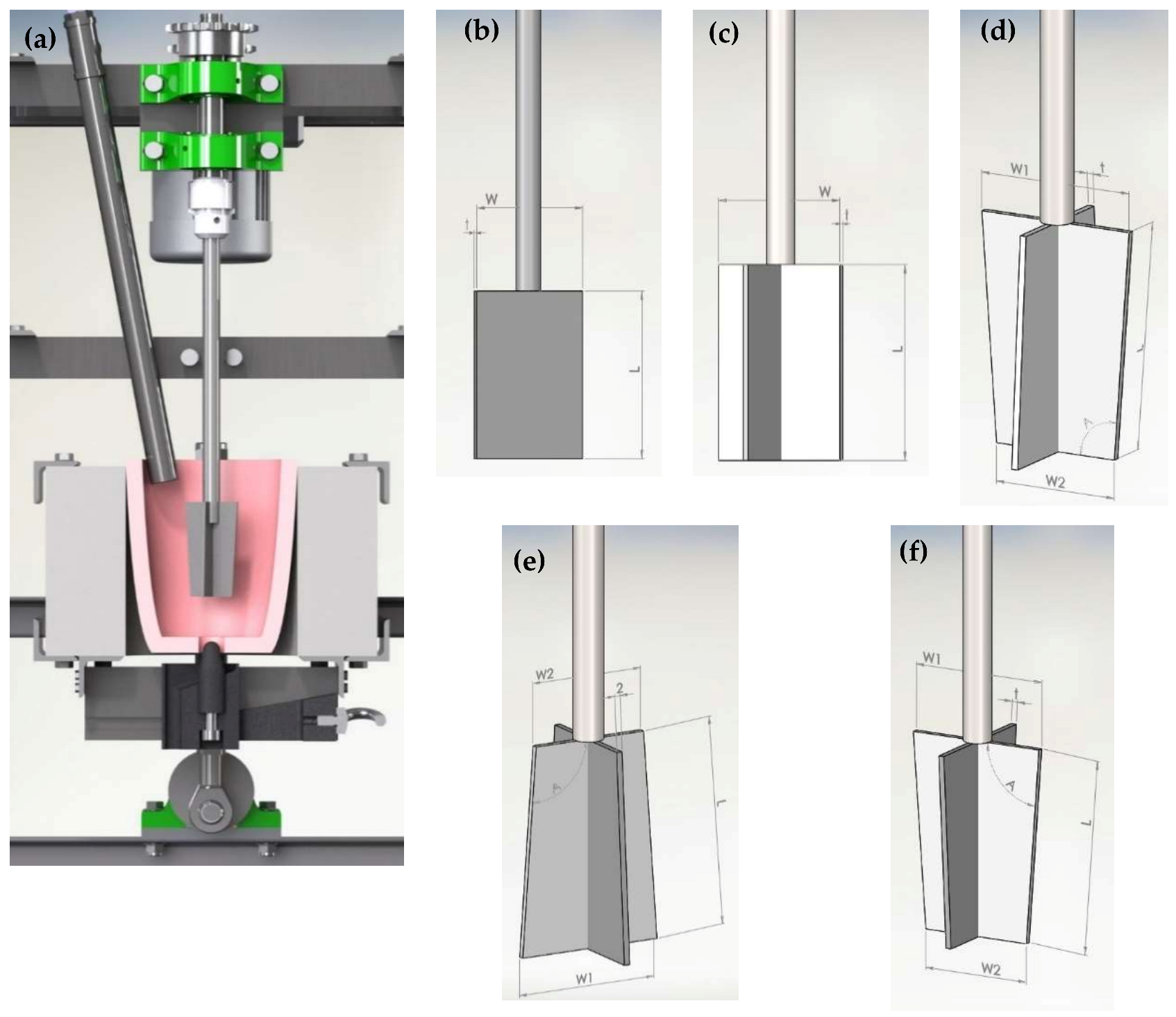
2.2. Casting Procedure

Casting setup: Figure 1a shows the setup used for casting the MMC blocks. The Al alloy was melted in a graphite crucible having an A8-size, (2.7 kg) using an electric resistance heating furnace (the setup is designed and produced by the authors throughout the current research program) (). The vortex method was applied for mixing the SiC particles in the molten metal, where an impeller (stirrer) composed of blades mounted on a central hub and rotated by a drive shaft was used to mix the molten Al and SiCp. The SiCp powder was delivered using a tube connected to an argon cylinder to maintain an inert atmosphere throughout the process and to prevent the formation of oxides. A bottom plugging mechanism was employed for the purpose of pouring the melt from the bottom of the crucible, which offered the twofold advantage of enabling stirring while pouring, along with keeping any oxides formed at the top from reaching the mold.
The stirrer geometry: To determine a suitable impeller shape, which creates flow pattern that can achieve the homogeneous distribution and dispersion of SiCp in the Al melt, the stirring/mixing process was simulated with water at room temperature. This is because the viscosity of molten Al (at 700 °C = 1.1~1.3 kg/.s) resembles that of water at room temperature. The vortex (flow pattern) formed due to stirring was observed and recorded by video camera EOS 1300D (Canon, Tokyo, Japan), and the progress of particles dispersion into water was examined. A similar approach was recently reported by Kumar et al. whereby glycerol water was used to simulate the viscosity of liquid Al during the selection of the stir-casting parameters [15]. In the present work, several flat-blade stirrer types (shapes) (Figure 1b–f) were experimentally investigated. Additionally, different water depths and different area fractions in the horizontal plane were examined. Powders of different materials with different densities were used to observe floatation above or sinking into the liquid. An axial flow impeller was found to be very effective in mixing solid–liquid suspensions because they prevent the solid particles from settling at the bottom of the tank. The stirrer actually use in the Al melt was coated with 2 layers of Thermodur R, a water-based graphite protective coating, whereby the stirrer was dipped into a beaker containing the liquid coating and removed and left to dry; this process was repeated twice. The coating layer was applied to prevent the reaction between the stirrer and the melt and the consequent incorporation of iron atoms into the melt.
Specifying the casting parameters: Specifying the most suitable casting parameters for an effective mixing process and for minimum porosity requires a great deal of experimentation. In addition to defining the optimal stirrer speed, feeding rate, and melt temperature, the stagnant regions in the melt crucible were avoided via the use of a reciprocating crucible. To improve the SiC particles wetting and to compensate for the Mg oxidation loss during the melting procedure, a total of 0.7 wt.% Mg was divided into two pieces, and one piece was added halfway through the process, while the second was added right before the final mixing stage. The pieces were covered with Al foil to prevent the burning of the Mg when coming into contact with the melt. Excessive addition of Mg was avoided to avert the formation of magnesium silicide. MMC blocks with dimensions of 15 × 30 × 170 mm and 5, 10, and 15 vol.% SiCp were cast for using the F350 and F500 particle sizes, and blocks with 5 and 10 vol.% SiCp were cast for the finer F800 size. For comparison purposes, an additional unreinforced Al6063 block was cast via the stir-casting machine (Figure 1a), and subjected to the same rolling schedules.
Cast blocks preparation: Prior to further processing, the cast blocks were milled down to a thickness of 14.3 mm to remove the cast surface, homogenized for 8 h at 535 °C, and followed by fan cooling [16]. The chemical composition of the blocks after casting is given in Table 1. The composition satisfies that of Al6063 according to DIN EN 573-3. The contents of Mn, Zn, Ti, Cr and Cu are kept well below the upper level recommended by the standard (0.1 wt.%). Additionally, the Mg oxidation loss during the long stirring process was substituted, so that the Mg content of the cast blocks fell within the standardized Mg range for Al6063.

2.3. Hot Deformation Simulation

Before hot rolling the MMC-blocks, the hot deformation behavior of the homogenized material was investigated. For this purpose, the deformation dilatometer Bähr Dil 805D (TA instruments, New Castle, DE, USA) was used. Cylindrical specimens with a diameter of 5 mm and a length of 10 mm were machined out of the homogenized blocks. In order to have the path of compression-loading in the same direction as that of the thickness reduction during rolling, the samples were machined with their lengths aligned with the thickness direction of the blocks. The simulations were performed by heating the specimens to 450 °C for 5 min, followed by compression at strain rates ( φ ˙ ) of 1 s−1 and 10 s−1.

2.4. Hot Rolling

For further improvements in SiCp dispersion and distribution as well as reducing the porosity percentage, the homogenized blocks were rolled down in 10 stages into sheets with a thickness of 1.2 mm applying total reduction of 92%. The hot rolling was carried out at 450 °C using a two-high rolling mill with 305 mm diameter rollers (HPT GmbH, Mülheim an der Ruhr, Germany). An intermediate re-heating to 450 °C for 15 to 30 min was applied between the rolling steps, depending on the rolling thickness. The results of the hot deformation simulations were utilized in defining the allowable strain per pass and the applied strain rate as is shown later.

2.5. Heat Treatment and Tensile Testing

Standard sub-size flat tensile specimens with a 6.4 mm width and 25.4 gauge length were machined out of the rolled sheets as well as the as-cast blocks in accordance with ASTM-Standard E8. Half of the samples were tested in the as rolled condition, while the other half were subjected to a T6 treatment by solution treatment at 535 °C for 8 h followed by fan cooling to room temperature and then age hardened at 177 °C for 10 h [17]. Tensile testing was performed using a UTS tensile testing machine (Zwick Roell Geoup, Ulm, Germany)at a cross head speed of 1 mm/min. The testing machine was equipped with a video extensometer for monitoring the strain.

2.6. Microscopy

Metallographic samples were prepared following the conventional preparation procedures, including mounting and grinding followed by polishing. The polished specimens were etched using Barker’s reagent (50 mL HBF4 + 1000 mL H2O). Light optical microscopy (LOM) using Olympus BX60M (Olympus Corporation, Shinjuku-ku, Tokyo, Japan), whereas scanning electron microscopy was performed using a CamScan SEM (Applied Beams, Beaverton, OR, USA) equipped with an Eumex Sphinx 133 Energy-dispersive X-ray spectroscopy (EDX) analyzer. To measure the SiCp and porosity contents, the specimens to be analyzed were cut from both ends of the cast block or from the middle of the rolled sheet. The systemic point count method was used to estimate the SiCp and porosity content in vol.%. A total of about 40 LOM images were taken per specimen, and the average value was calculated from the results of the samples obtained from both ends of each cast block.

3. Results and Discussions

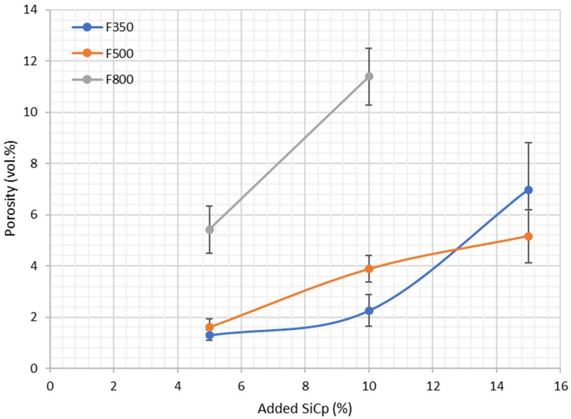
3.1. Technological Parameters of Successful Casting

To conclude the trials and determine the most suitable stirrer (see Section 2.2), a complex axial stirrer composed of 4 double-angled blades and occupying almost 70% of the cross-section of the crucible was found effective in achieving both the insertion and distribution of the particles into the water. The blades were fixed to the rotating spindle in a configuration cross-oriented to the direction of the plane, where two blades in one vertical plane are inclined downwards, while the two others in the cross vertical plane are inclined upwards; the selected stirrer is shown in Figure 1d.
The successful castings were defined based on optical assessment of the distribution of SiCp in the matrix (investigated under LOM) and the complete filling of the molds. The most successful castings were found to be obtained by adopting the following procedure: An argon purge was started when the crucible temperature reached 600 °C. Stirring started at a speed of 1000 rpm when the melt temperature reached 730 °C. Right after stirring started, SiC dosing with a dosing time of 15 min per 5 vol.% SiC was added (approximate rate of 11 g.min−1). The final mixing continued for 5 min after SiC dosing was completed, and stirring was continuous while casting.

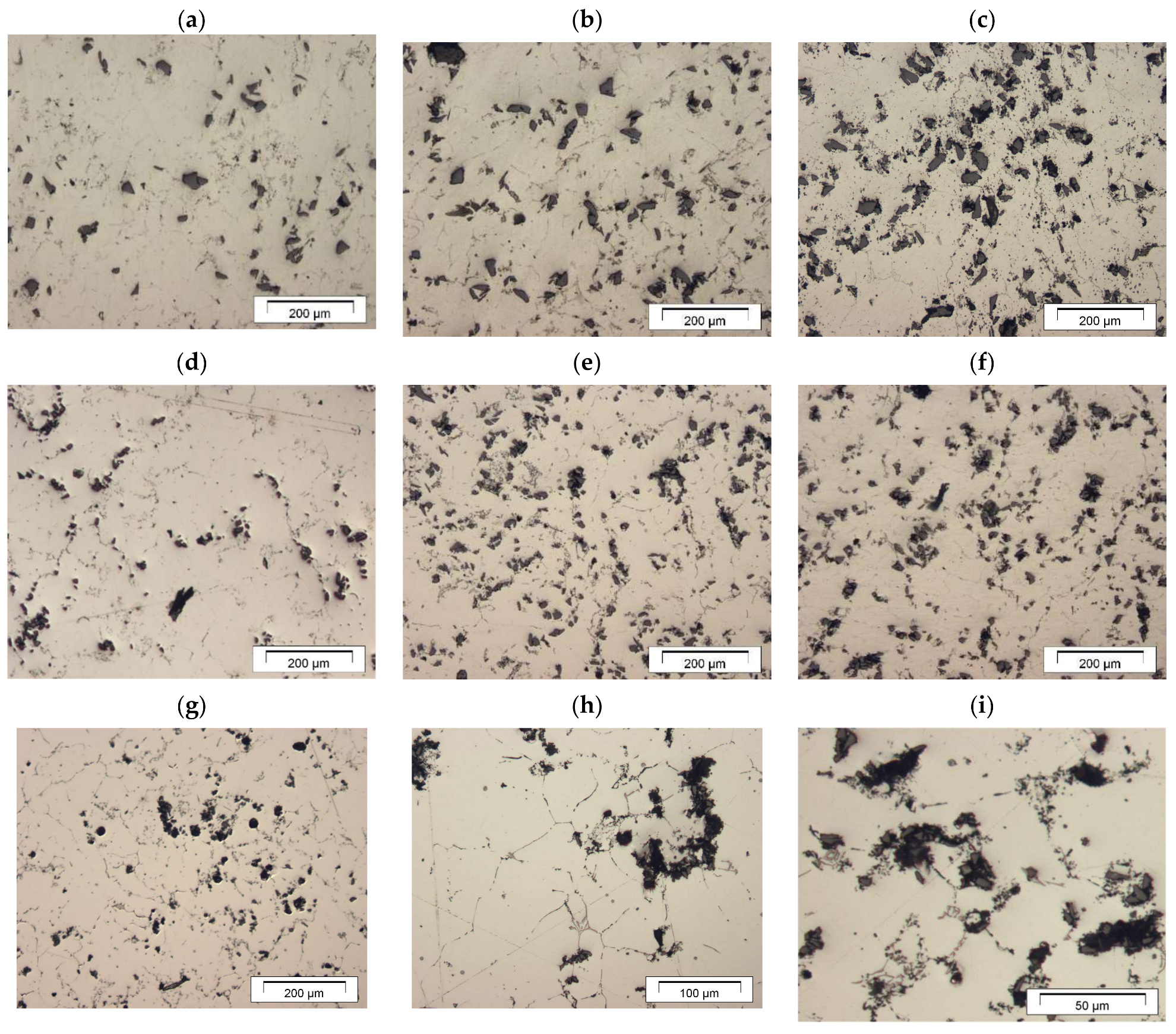
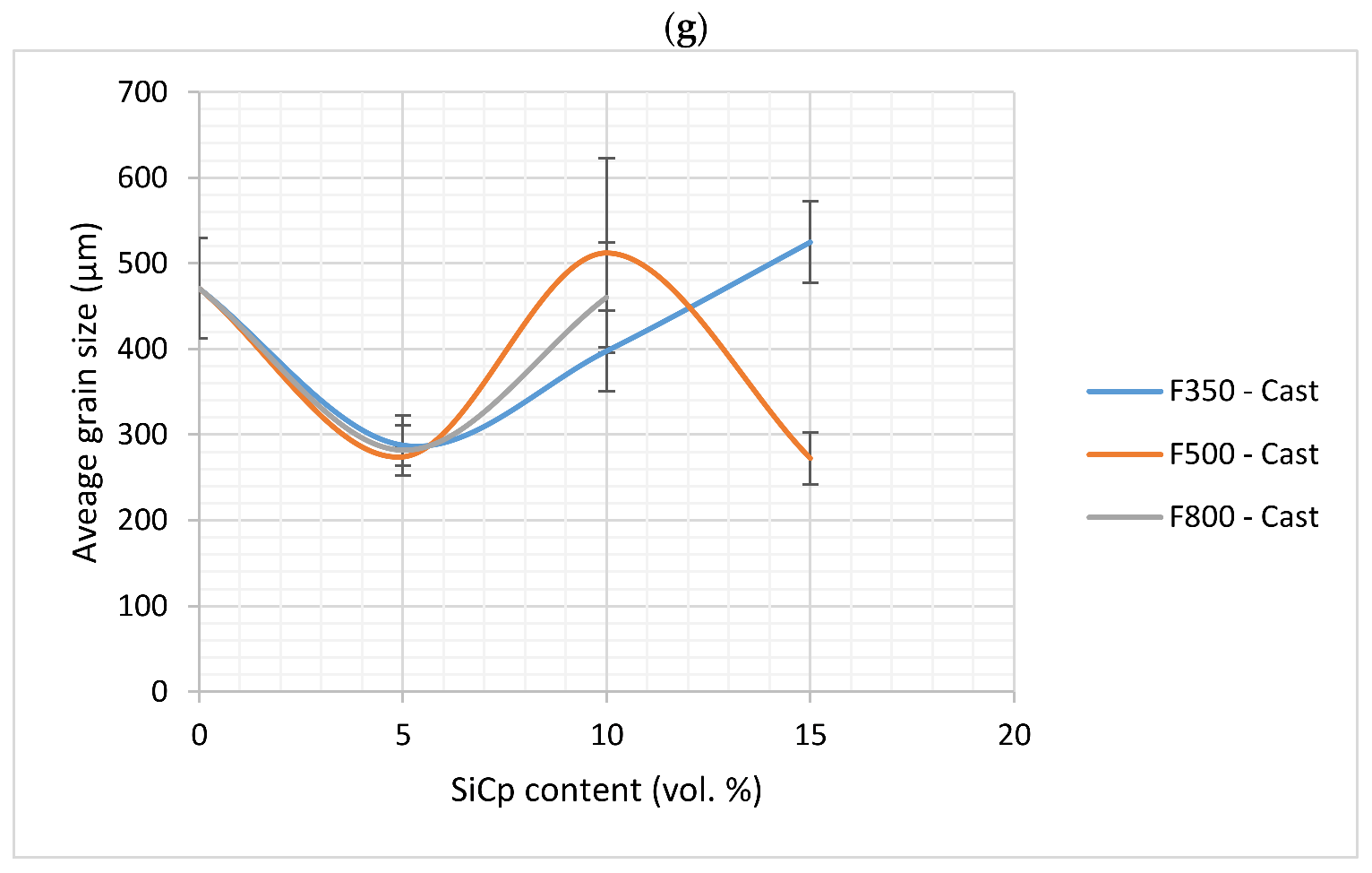
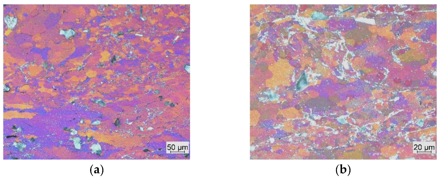
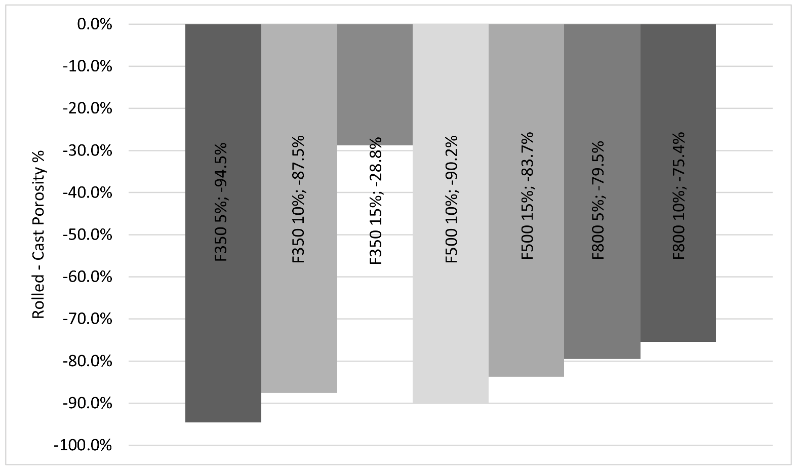
3.2. As-Cast Structures

Figure 2 shows the as-cast microstructures of the MMCs produced. It can be seen that the SiCp distribution is homogenous and there was an absence of agglomerates in the F350. However, the finer F500 SiCp showed evidence of slight agglomerations, which was more evident with increasing vol.% of the SiCp. By decreasing the particle size to the finest one, F800, significant agglomerations appeared, even in the 5% SiC specimens.
In order to explain why finer sizes such as 8 µm F800 particles show a higher tendency to develop agglomeration features, the shear stress applied to the particle clusters that should overcome the cohesive force between the SiCp should be estimated (Babu et al., 2008) [18]. The shear rate ‘γ’ can be expressed as a ratio between stirrer frequency ‘n’ and geometric parameter ‘k’ according to the following equation:
γ = 4 π n 1 k 2
where ‘k’ is the ratio between the stirrer diameter ‘dS’ and the crucible diameter ‘DC
k = dS/DC
Shear stress ‘τ’ (Pa) during mixing is calculated in terms of the total solid fraction according to:
τ = ηc · γ
η, the viscosity is a function of the stirring temperature. ‘γ’ is the shear rate.
The viscosity of aluminum in the liquidus state (η = 0.0015 Pa.s) is similar to that of water at room temperature. Therefore, water can be used in the physical simulation of flow patterns for aluminum melt (see experimental section). However, the viscosity increases by the implementation of SiCp. In case of stirring at temperatures close to the melting point (e.g., 670 °C), the viscosity increases to 1 Pa.s. Data on viscosity in relation to SiCp volume fraction are not available according to a review of the known literature. However, the dependance of the viscosity of composite slurries on the reinforcement characteristics can be calculated, e.g., by the equation developed by Wang et al. [19]. This equation estimates the viscosity of composite slurries (ηc) as a function of the viscosity of the fluid without any particles (η) and considering the influence of particle size (d), the aspect ratio of SiCp (ξSiC), and the volume fraction of SiC (Vf) according to the equation:
η c = η   [ ξ SiC 1 + d 0.95 0.01 + 37.35 d 0.95 V f ]
The critical shear stress, τc for SiCp with an average size of 4 µm is 300 kPa [20].
τc = α (1/d2)
where d is the particle size.
In the present case, by using 15 µm F500 particle size: τc (F500) = 300 × (4/15)2 = 21.3 kPa.
This means that the applied stress (22.5 kPa) is theoretically just above the critical shear stress (21.3 kPa).
This explains why the finer size, 8 µm F800, shows a lot of agglomeration features with a critical shear stress τc (F800) = 300 × (4/8)2 = 75 kPa
Therefore, the ratio of agglomeration increased by increasing the vol.% of SiCp and by decreasing their size. Another concern with the cast MMC blocks was the presence of casting porosity. Figure 3 demonstrates that a continuous increase in the porosity vol.% was associated with increasing the SiCp content. Reinforcing the MMCs with F800 SiC powder resulted in a significantly porous cast, with a porosity reaching 11 vol.% when adding 10 vol.% SiCp. Indeed, the formation of porosities during the production process of MMCs is common because of the long duration of particle feeding. A number of factors were reported to cause the presence of porosity in stir-cast MMCs, among them is shrinkage during solidification as well as the entrapment of gasses caused by the stirring process [21]. Additionally, the increase in surface area in contact with air caused by decreasing the particle size results in increasing porosity vol.% with decreasing particle size [22]. The produced MMCs shown in Figure 2 present an improved quality, with significantly reduced agglomerations and porosity compared with our work previously reported in [9,13], in which the cast MMCs were produced using the conventional vortex method.
Representative etched micrographs of the as-cast microstructures are illustrated in Figure 4. A drop in the average grain size from 470 µm to about 270–290 µm with the addition of 5 vol.% SiCp was observed. Further additions of SiCp beyond 5 vol.% yielded increased grain size. The adverse effect of increasing SiCp content might be the reason for the observation that the large areas where deplatation in SiCp was observed are larger. An exception was observed in the F500 size, which experienced an initial increase in grain size after adding 10 vol.% SiCp, followed by another decrease back to the value recorded for the 5 vol.% SiCp conditions. This was attributed to the improved SiCp distribution (Figure 4d) compared with the others at 10 and 15 vol.%.

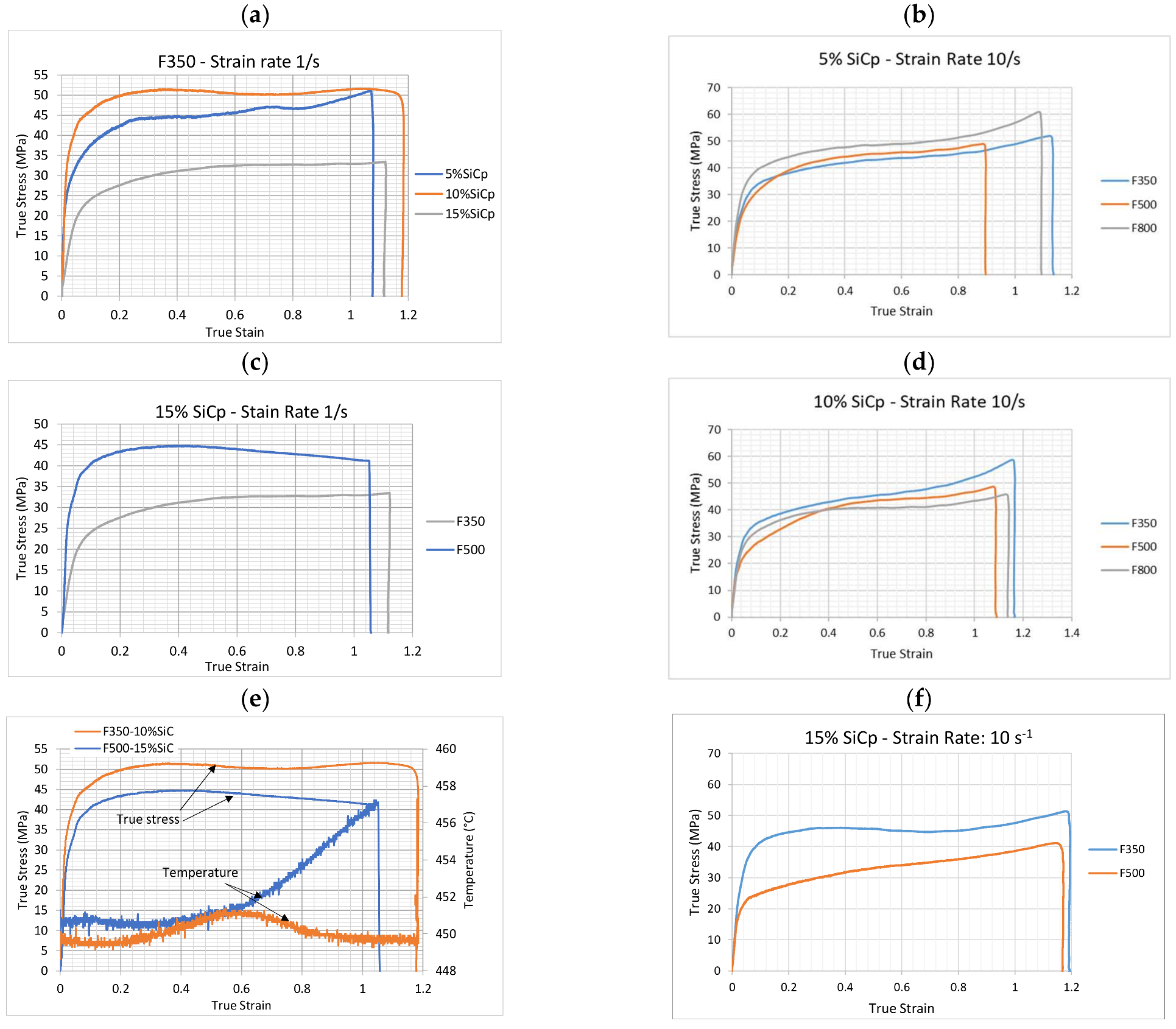
3.3. Hot Deformation Simulations

Figure 5 shows the true-stress–true-strain curves of the hot compression tests carried out at 450 °C applying a true-strain rate ( φ ˙ ) of 1 s−1 and 10 s−1. Generally, increasing the strain rate results in increasing both the flow stress and the work hardening of the tested samples. As shown in Figure 5a,c, the flow curves of the samples strained with φ ˙ = 1 s1 reach a steady state at a true strain (φ) of about 0.3, which indicates the start of softening by continuous dynamic recrystallization (CDRX). This value is slightly affected by the size and content of SiC particles in the MMCs. The CDRX implies a smooth change in the microstructure by a progressive formation and rotation of sub-grains as deformation proceeds [23,24]. The occurrence of CDRX in aluminum and Al-MMCs was reported by many authors and can be attributed to the high stacking-fault energy (SFE) of aluminum [24,25,26]. At this strain level, a predominantly recrystallized structure with grains finer than the starting ones should be presented. In order to verify the occurrence of dynamic recrystallization at φ ˙ = 1 s−1, additional compression tests up to φ = 0.46 at φ ˙ = 1 s−1, followed by microstructural investigations, were conducted. A representative result is shown in Figure 6, where equiaxed grains are predominantly observed in the structure of the 5 vol.% F350-SiCp MMC strained to φ = 0.46. It is observed in Figure 6 that the dynamic recrystallized grains nucleated both in the Al matrix and at the SiCp/matrix interfaces. The latter grains were observed to be finer than the former grains. This observation is related to the strain distribution during plastic deformation at the SiCp/matrix interface and is in line with the observations of Xia et al. [25]. The dynamically recrystallized structure produced grains finer than those of the as-cast structure. Applying a strain rate of 10 s−1 results in a continuous strain hardening of the material, except in case of the F350 MMCs with the highest content of SiCp (15 vol.%). Indeed, the existence of SiCp in the matrix resulted in providing nucleation sites for the formation of globular grains [9]. This had a significant effect on improving the cast structure so that dynamic recrystallization could take place. Therefore, when starting dynamic recrystallization at high φ ˙ levels, a higher SiCp content is required. The results of Figure 5b–d highlight the importance of the particles in the MMCs for activating dynamic recrystallization. It is worth mentioning here that the fluctuation in the stress-strain curves during CDRX of Figure 5a,c,e is correlated to unstable temperatures during hot compression, as indicated in Figure 5e.
Therefore, the hot deformation tests indicate that applying a strain rate of 1 s−1 improves the cast structure of all produced MMCs via dynamic recrystallization.

3.4. Rolling Schedule

The rolling-schedules for producing the sheets were defined based on the results of the hot deformation tests. The sheets were rolled from 14.3 mm to a final thickness of 1.2 mm, which is equivalent to a total reduction of 92%. In order to define the rolling speed (in revolutions per minute, rpm) that corresponds to a strain rate of 1 s−1 so as to result in dynamic recrystallization, Sims equation, Equation (5) was used [27].
φ ˙ = 2 π N 60 r R H ln H h
where φ ˙ is the effective true strain during rolling (in s−1), N is the rolling speed in rpm, R is the radius of the curvature of the elastically deformed roll (assuming that the deformation of the mill stand is negligible, R approximately equals the rolling mill radius, R), H is the entry thickness of the sheet, h is the thickness of the sheet after rolling, and r is the reduction in pass (r = (H − h)/H).
Given that the rolls used in the current investigation had a radius of R = 150 mm, accordingly, the N value that corresponds to φ ˙ = 1 s−1 can be calculated for each deformation step. Based on thermomechanical results, the rolling schedule was designed as given in Table 2. The rolling speed of 4 rpm, which corresponded to φ ˙   = 1 s−1, was applied for the first 5 five steps. The schedule started with the initial step with φ = 0.46 to encourage the dynamic recrystallization and resulted in predominantly recrystallized finer structures as described in the previous section. This was followed by a gradual reduction in deformation strain until the fifth step, to a value of 0.15. This maintaned a strain rate of 1 s−1 at the same rolling speed of 4 rpm. The advantage of the gradual reduction of φ is lowering the susceptibility of the MMCs to edge cracking [9]. After performing numerous rolling steps (here selected to be five steps), the structure characteristics would be improved as a result of the deformation’s effect on refining the grain size, reducing the number of cast porosities, and improving the SiCp distribution. Subsequently, the final five steps were selected with increased φ ˙ up to 2.1 s−1 and φ up to 0.24 to obtain a final refined microstructure. The parameters used for the final steps resulted in a pancaked strain-hardened structure (as is shown in the next section), which grants high strength and hardness to the MMCs. Therefore, the first five rolling steps were performed according to the rolling schedule that avoids materials cracking, whereas the last ones were used for improving the hardness and strength of the MMCs. The sheets were reheated to 450 °C after each rolling step in order to compensate for the heat loss during rolling. The intermediate reheating time was for 30 min after the first rolling step and for 15 min after the following ones. The sheets possessed post-dynamic recovery and eventually post-dynamic recrystallization during these intermediate reheating steps.
Another source of cracking in the particulate-reinforced MMCs, as indicated by the work of [9], is the hoop stresses induced on the circumference of the thermomechanically processed samples. These stresses are known as the reason for initiating side-cracks. Once initiated, the rolling process should be stopped, and the side edges should be trimmed to remove the cracked regions. For the 5 and 10 vol.% SiC, only one edge-trimming operation was required after eight rolling passes. An exception was given for the F800-10 vol.% SiCp, which required two edge-trimming processes at the third and eighth stages. This could be attributed to the higher degree of agglomeration caused by its finer particle size. For the 15 vol.% SiC specimens, two trimming processes were required at the fifth and ninth stages, owing to the higher SiCp vol.% and consequently heightened propensity for cracks to initiate at the sides.

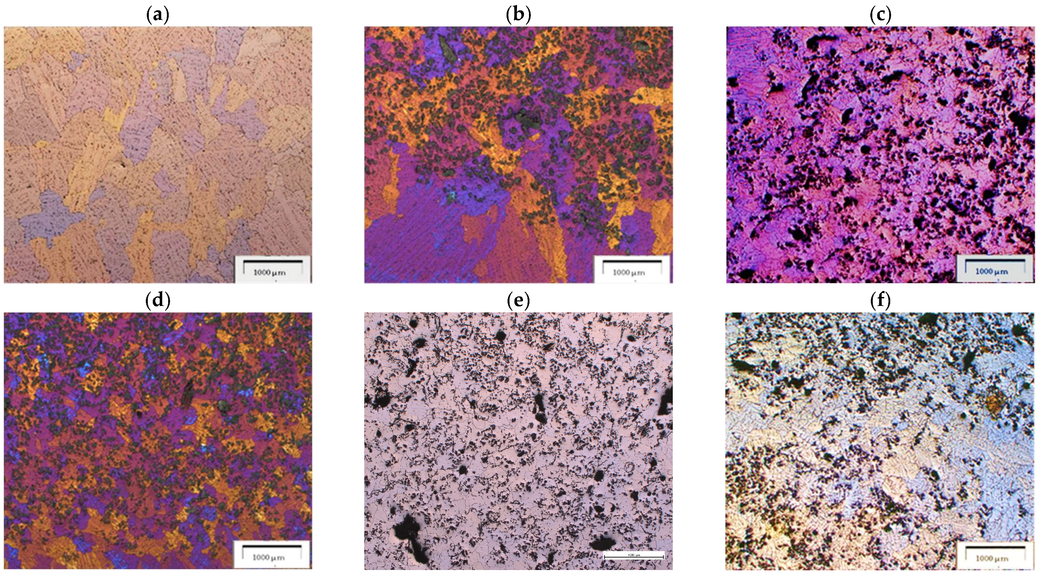
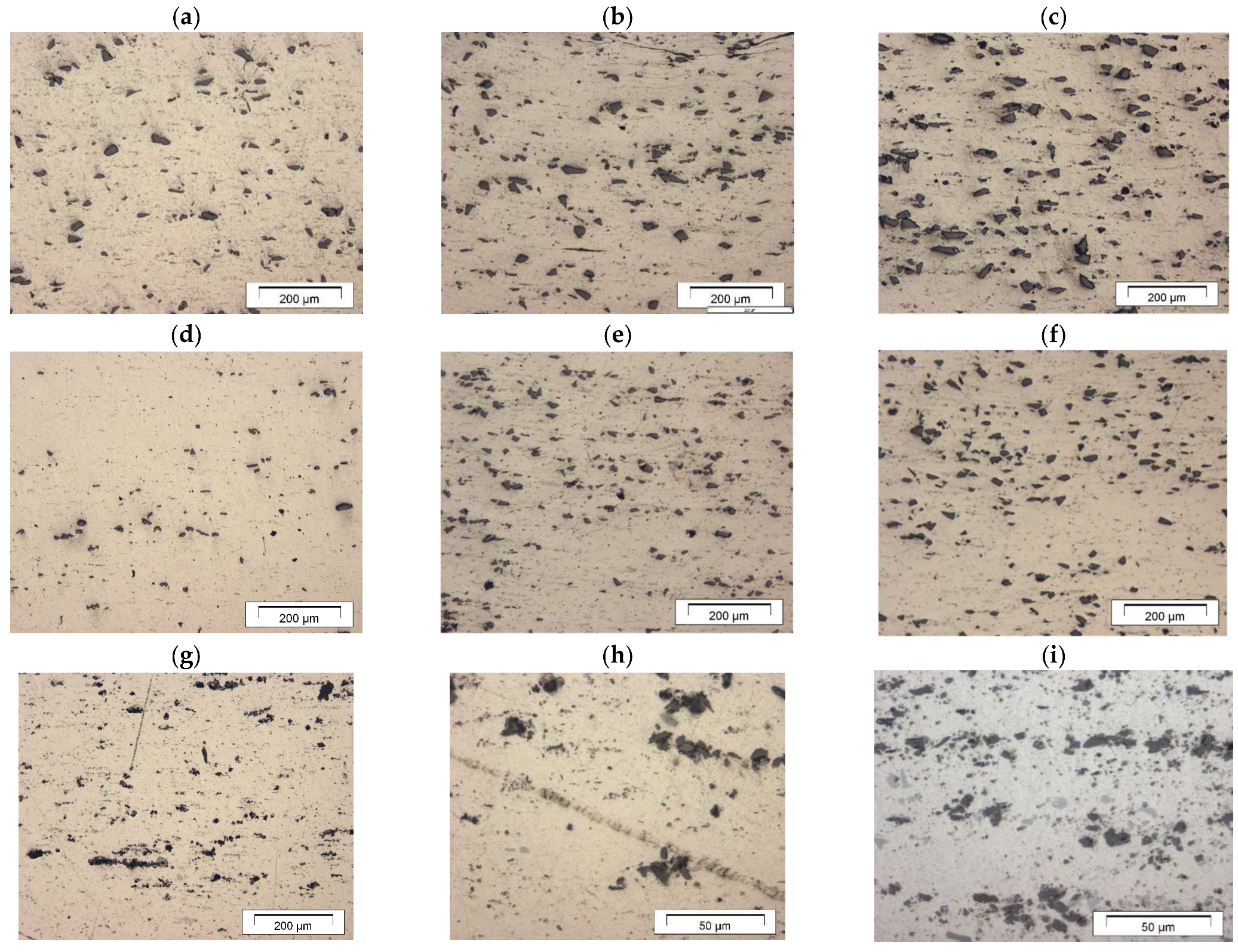
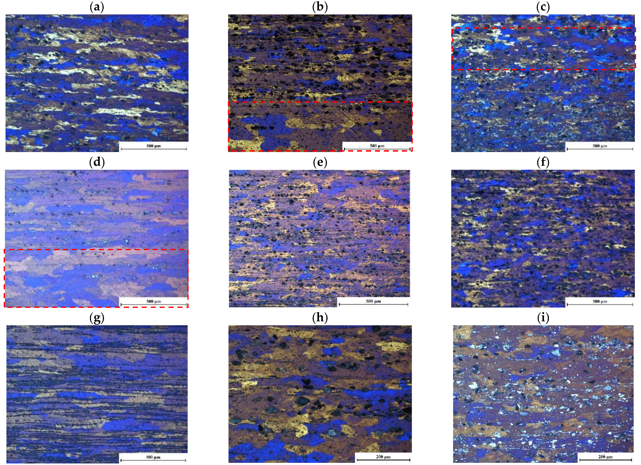
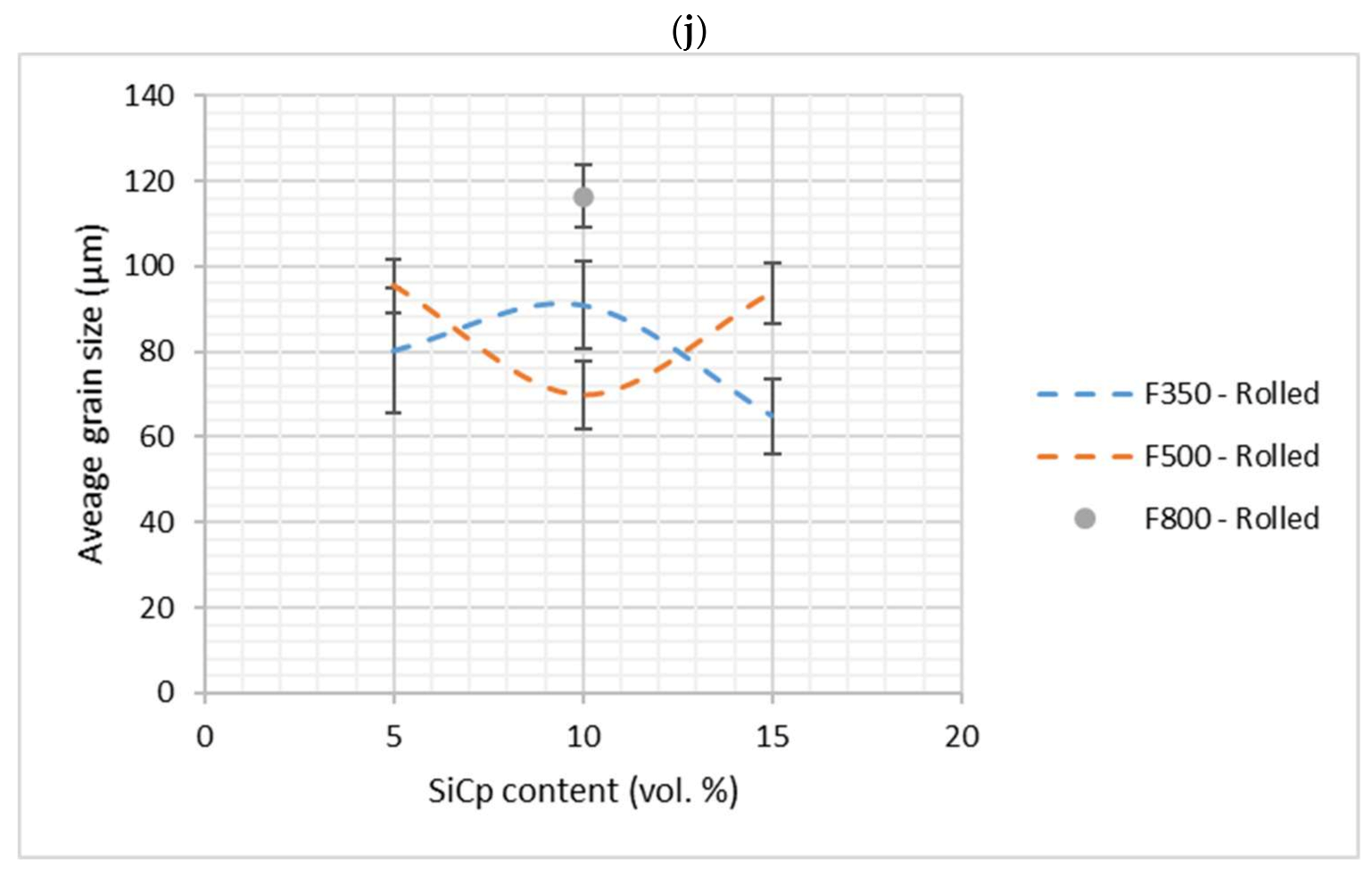
3.5. As-Rolled Microstructures

Figure 7 shows the microstructures after rolling with different magnifications. Comparing this figure with Figure 2, it can be inferred that hot rolling improved the dispersion of SiCp in the matrix. The F350 and F500 microstructures exhibited excellent particle distributions, while the phenomenon of SiCp agglomerating around porosities was almost non-existent. Although the rolled F800 microstructures (Figure 7g–i) revealed an improved distribution of SiCp compared with the as-cast conditions (Figure 2g–i), they still suffered from the presence of agglomerations in the rolled sheets. While observable agglomeration exists, the dispersion is considered to be much better compared with the MMC microstructures obtained from the work done with SiCp possessing the same particle sizes and produced using the conventional stir casting method [9,13].
Another reported merit of rolling is that it reduces the specimen’s porosity; this is also supported by the current experimental results, as shown in Figure 7. Porosity reductions of 75–85% were recorded for most conditions after rolling, with a maximum reduction of 94.5% for the F350-5% conditions. On the other hand, the F350-15% condition displayed a much lower porosity reduction, recording only 28.8% lower porosity compared with the as-cast condition, which was expected to adversely affect its mechanical properties. In all cases, increasing the vol.% of SiCp resulted in a significant decrease in the rolling ability to reduce the porosity present in the as-cast MMCs. The porosity pattern of the as-rolled composites was found to be elongated and aligned in shape instead of being globular, as in the case of the as-cast composites. Similarly, the SiCp were observed to be aligned with the rolling direction. Additionally, Figure 7 shows regions completely depleted of SiCp reinforcement. These regions were inherited from the as cast structure. This observation is more significant in the F500-5% SiC MMC (Figure 7d).
Figure 8 shows the etched microstructures for the MMCs after rolling. All the MMCs microstructures exhibited elongated grains in the rolling direction. The elongated form of the grains resulted from the adopted schedule in which the last five rolling steps were designed to avoid recrystallization during the rolling process. The elongated grains were observed to be finer with increasing vol.% of SiCp. The SiCp acted as heterogeneous nucleation sites for the development of new grains during the first five rolling steps, where recrystallization was expected to take place. The hard SiCp did not deform during hot rolling, and the strain in the Al6063 matrix formed a deformation zone around the particles. Thus, recrystallization could easily take place in these deformation zones due to particle-stimulated nucleation [28]. Increasing the vol.% of SiCp provides more sites for the grains’ nucleation and hence results in finer recrystallized structures during the first five rolling steps and hence finer pancaked structures in the following rolling steps. Figure 8b–d reveal heterogeneity in grain size, where the regions with larger elongated grains are associated with zones depleted by SiCp reinforcement (marked with red, dashed rectangles). The larger grains were a consequence of the absence of heterogeneous nucleation sites due to the absence of SiCp in these regions. Therefore, these grains do not possess refinement due to dynamic recrystallization during the first rolling steps. On the other hand, using finer reinforcing powders resulted in producing finer grains of the matrix, as clearly observed in Figure 9, particularly in the higher magnification micrographs (Figure 8h,i). Reinforcing with finer SiCp resulted in providing more nucleation sites for the formation of new grains and hence finer grained matrices. The grain-size measurements presented in Figure 8j indicate a reduction in average grain size to values of 85 µm for all conditions after rolling an average of 420 µm in the as-cast condition. As mentioned above, not all the grains were refined during the first rolling steps due to the depletion of some zones in SiCp. This resulted in higher average grain size after rolling.

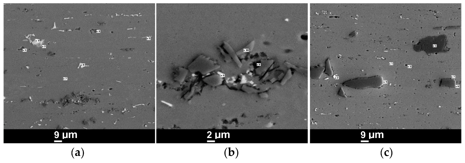
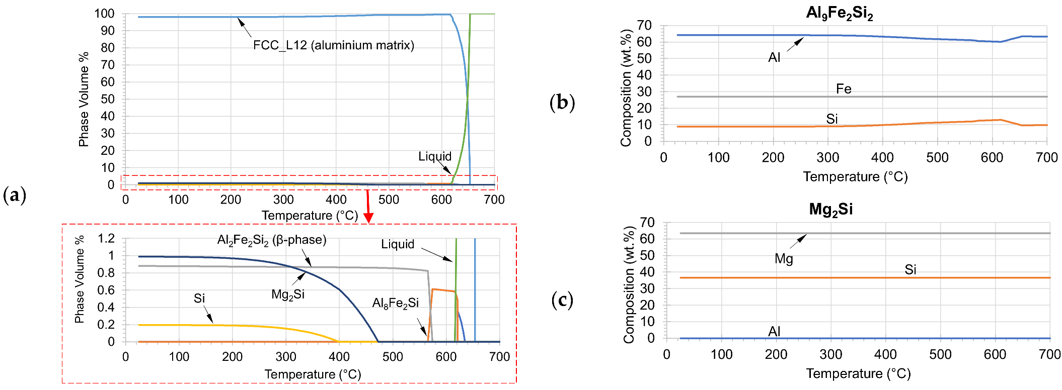
3.6. Analysis of the Intermetallic Phases

Figure 10 shows SEM micrographs of the F800 and F350 SiC 10 vol.% in the as-rolled condition. EDX analysis shows several intermetallic phases that differ according to their Fe and Mg contents, see Table 3 and Table 4. Based on thermodynamic calculations using ThermoCalc (Version 2020.1.60405-124, Thermo-Calc Software, Stockholm, Sweden) applying database TCAl4-v4.0, two types of intermetallic phases were predicted to exist at room temperature (RT), namely Mg2Si (magnesium silicide) and Al9Fe2Si2 (β-phase). Figure 11b,c shows that the complete dissolution of the former intermetallic phase is predicted to take place at 470 °C and of the latter at 575 °C, respectively. The Si-element was predicted to start precipitating at ~400 °C (Figure 10) and form the eutectic structure with the Al-matrix [29]. The white particles in the microstructure of Figure 10 contained an abundance of Fe and an absence of Mg content, as given in Table 3. These particles correspond to the predicted Al9Fe2Si2, the β-phase. The predicted chemical composition of the β-phase (Figure 11b) is similar to that measured by using the EDX of the white intermetallic phase. On the other hand, the dark-grey particles that contained a high Mg level, and were readily found within, corresponded to the Mg2Si intermetallic phase. Indeed, the Al is predicted to be absent in this phase. The source of the Al in the EDX analysis is probably the background matrix, and therefore decreased the accuracy of the EDX analysis. Furthermore, a black-colored phase is more readily found at the SiC–Al matrix interface.

3.7. Tensile Properties

Figure 12 shows the changes in ultimate tensile strength (UTS), yield strength, and total elongation by changing the SiCp vol.%. As shown in Figure 11a, there was a small yet consistent increase in the UTS with increasing the SiCp volume fraction in the ‘As-Rolled’ condition, with the exception of the F350-10% SiCp, F500-5% SiCp, and F800 5% SiCp conditions. These three conditions notably exhibited the presence of regions depleted of SiCp discussed earlier. These regions exhibited enlarged grains (see Figure 8b,d,h), which may present the reason for lower strength in the MMCs. The change in yield strength with SiCp vol.% shown in Figure 12b illustrates a similar trend to that in Figure 12a.
The improvement in the tensile strength of the MMCs due to increasing SiCp vol.% can be attributed to strengthening mechanisms such as load transfer, grain refinement, and dislocation formations [28]. Furthermore, the Orowan strengthening mechanism contributed to the increased UTS by inhibiting the movement of dislocations. By further application of stress, the dislocation bypassed the particles by forming a loop around them. The formation of dislocation loops raised the stress required for deformation, thereby increasing the strength [30].
A more significant strength improvement due to additions of SiCp can be noticed in the ‘T6 Treated’ specimens, where the tensile strength increased from 156 MPa up to 236, 215, and 254 MPa after the addition of 10 vol.% SiCp F350, F500, and F800, respectively, compared with an increase of 40 MPa in the case of the base material. As previously concluded by Mohamed and Churyumov [31], the introduction of the SiC particles into the structure of the Al-matrix alloy leads to an acceleration of the aging process. For the present observation, it is proposed that this acceleration results in approaching the optimal aging condition for the 10 vol.% SiC at the applied aging conditions (177 °C for 10 h) and hence the peak in the strength curves as shown in Figure 12a,b. Regarding the 15 vol.% SiC, MMCs, the optimal point might have been exceeded by holding it for a longer time, therefore a decrease in the strength was observed due to over-aging. In all cases, the increase in UTS was the result of the dissolution of Mg2Si particles at 535 °C during the solution treatment and their fine precipitation throughout the microstructure during aging. On the other hand, there is no clear correlation for the effect of SiCp particle size on the increase in tensile strength after age hardening, where the F500 variant recorded lower tensile strength compared with the other two particle sizes studied at the 5 and 10 vol.% compositions. Figure 12a also shows the trend where the strength started dropping beyond an SiCp addition of 10 vol.% in the T6 age-hardened condition. This may be correlated to the higher crack sensitivity of the hardened, T6-treated matrix. Therefore, increasing the vol.% of SiCp beyond 10% is not recommended for T6-treated MMCs.
Figure 12b shows a steady drop in ductility in terms of the total elongation to rupture by increased SiCp vol.%. It is evident that the ductility increased after the T6 treatment, which can be attributed to the recrystallization of fresh undeformed grains replacing the pancaked structure in the as-rolled condition. The insignificant increase in ductility exhibited by the F800-10% specimen could be attributed to its inferior state of dispersion when compared with the other specimens. This would consequently lead to recrystallization rates lower than that experienced by the other—better dispersed—conditions.

4. Conclusions

Al6063-SiCp MMC sheets were successfully produced via an economical process that employs stir casting and subsequent rolling. The first five rolling steps were performed allowing for dynamic recrystallization to take place, the purpose of which was to avoid cracking, whereas the last ones were performed with respect to improving the hardness and strength of the MMCs via producing a pancaked structure. A uniform distribution of the reinforcement particles was successfully achieved; deviations from the uniformity in the cast structures were still improved during the rolling phases. The following conclusions can be drawn from the current study:
  • The as-cast structure can be improved by applying proper temperatures and deformation rates that result in dynamic recrystallization. The parameters of save rolling in the current study were observed to be a deformation rate φ ˙ = 1 s1 (corresponding to 4 rpm) and a rolling temperature of 450 °C. The reduction ratios throughout the rolling step set were changed to keep a constant rolling speed.
  • Applying faster rolling speeds throughout the last rolling steps resulted in a pancaked structure.
  • Heterogeneity in grain size of the rolled Al–SiCp was observed, where the regions with larger, elongated grains were associated with zones depleted by SiCp reinforcement. The composites notably exhibited these regions and therefore marked heterogeneity in grain sizes showed inferior strength compared with the composites having more homogenously distributed SiC particles.
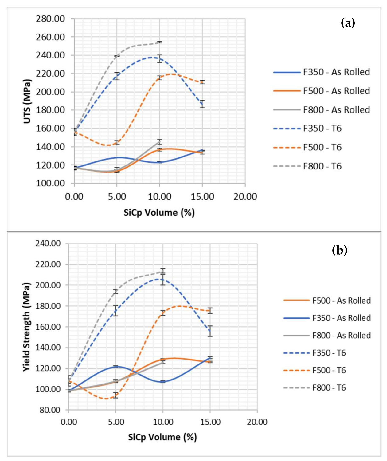
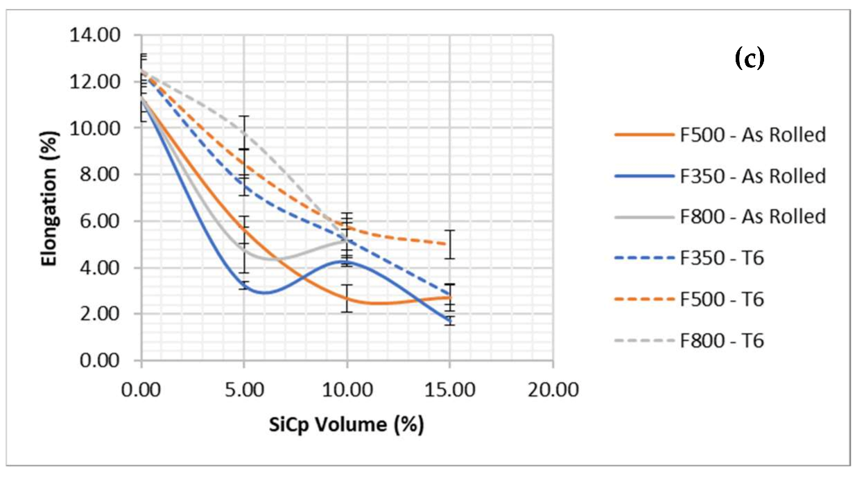
  • Due to the reinforcing effect of SiC, an increase in tensile strength of 15% to 25% in the as-rolled composites was observed. This increase came at the expense of ductility, which showed a 50–75% decrease.
  • A greater extent of strengthening due to additions of SiC was observed in the T6-treated composites compared with the as-rolled condition, with the former showing up to a 63% increase in strength.
  • The strength of the T6-treated Al–SiCp started dropping beyond an SiCp addition of 10 vol.%, which was correlated to higher crack sensitivity of the harder T6-treated matrix. Accordingly, increasing the vol.% of SiCp beyond 10% is not recommended for the T6-treated MMCs.

Author Contributions

Conceptualization, M.A.T., H.P. and A.E.; methodology, M.S., M.A., A.E. and M.D.; software, M.S.; validation, M.A. and M.D.; formal analysis, A.E.; investigation, M.S., M.A., and M.D.; resources, M.A.T. and H.P.; data curation, M.A. and M.D.; writing—original draft preparation, M.S. and M.A.; writing—review and editing, M.A.T. and H.P.; visualization, M.S. and M.A.; supervision, M.A.T. and H.P.; project administration, M.A.T. and H.P.; funding acquisition, M.A.T. and H.P. All authors have read and agreed to the published version of the manuscript.

Funding

This research was funded by German Aerospace Center (DLR), Germany, grant number IB 055 and the Science and Technology Development Fund (STDF), Egypt, grant number GERF 5128. The APC was funded by the Open Access Publishing Fund of Clausthal University of Technology.

Informed Consent Statement

Not applicable.

Data Availability Statement

The raw/processed data required to reproduce these findings cannot be shared at this time as the data also form part of an ongoing study.

Acknowledgments

We acknowledge financial support by the Open Access Publishing Fund of Clausthal University of Technology.

Conflicts of Interest

The authors declare no conflict of interest.

References

  1. Karthikeyan, B.; Ramanathan, S.; Ramakrishnan, V. Coefficient of Thermal Expansion Measurement of Metal Matrix Composites by Thermo Mechanical Analyser. Adv. Mater. Res. 2011, 264–265, 663–668. [Google Scholar] [CrossRef]
  2. Mahesh Kumar, V.; Venkatesh, C.V. Effect of ceramic reinforcement on mechanical properties of aluminum matrix composites produced by stir casting process. Mater. Today Proc. 2018, 5, 2466–2473. [Google Scholar] [CrossRef]
  3. Bodunrin, M.O.; Alaneme, K.K.; Chown, L.H. Aluminium matrix hybrid composites: A review of reinforcement philosophies; mechanical, corrosion and tribological characteristics. J. Mater. Res. Technol. 2015, 4, 434–445. [Google Scholar] [CrossRef] [Green Version]
  4. Sirahbizu Yigezu, B.; Mahapatra, M.M.; Jha, P.K. Influence of Reinforcement Type on Microstructure, Hardness, and Tensile Properties of an Aluminum Alloy Metal Matrix Composite. J. Miner. Mater. Charact. Eng. 2013, 1, 124–130. [Google Scholar] [CrossRef] [Green Version]
  5. Saenpong, P.; Talangkun, S.; Laonapakul, T.; Boonma, A. Microstructures and hardness of A356-SiC composites produced by the mechanical stir casting. Mater. Today Proc. 2018, 5, 9489–9496. [Google Scholar] [CrossRef]
  6. Peker, S.M. Solid-Liquid Two Phase Flow, 1st ed.; Elsevier: Amsterdam, The Netherlands, 2008; ISBN 9780080553412. [Google Scholar]
  7. Arab, M.S.; El Mahallawy, N.; Shehata, F.; Agwa, M.A. Refining SiCp in Reinforced Al–SiC Composites Using Equal-Channel Angular pressing. Mater. Des. 2014, 64, 280–286. [Google Scholar] [CrossRef]
  8. Nagaral, M.; Auradi, V.; Parashivamurthy, K.I.; Kori, S.A.; Shivananda, B.K. Synthesis and characterization of Al6061-SiC-graphite composites fabricated by liquid metallurgy. Mater. Today Proc. 2018, 5, 2836–2843. [Google Scholar] [CrossRef]
  9. El-Sabbagh, A.; Soliman, M.; Taha, M.; Palkowski, H. Hot rolling behaviour of stir-cast Al 6061 and Al 6082 alloys—SiC fine particulates reinforced composites. J. Mater. Process. Technol. 2012, 212, 497–508. [Google Scholar] [CrossRef]
  10. Bhat, B.V.R.; Mahajan, Y.R.; Prasad, Y.V.R.K. Effect of volume fraction of SiC p reinforcement on the processing maps for 2124 Al matrix composites. Metall. Mat. Trans. A 2000, 31, 629–639. [Google Scholar] [CrossRef]
  11. Alaneme, K.K. Influence of Thermo-mechanical Treatment on the Tensile Behaviour and CNT Evaluated Fracture Toughness of Borax Premixed SiCp Reinforced AA 6063 Composites. Int. J. Mech. Mater. Eng. 2012, 7, 96–100. [Google Scholar]
  12. Balogun, S.A.; Adeosun, S.O.; Sanni, O.S. The effects of cold rolling and heat treatment on Al 6063 reinforced with silicon carbide granules. JOM 2009, 61, 43–47. [Google Scholar] [CrossRef]
  13. El-Sabbagh, A.M.; Soliman, M.; Taha, M.A.; Palkowski, H. Effect of rolling and heat treatment on tensile behaviour of wrought Al-SiCp composites prepared by stir-casting. J. Mater. Process. Technol. 2013, 213, 1669–1681. [Google Scholar] [CrossRef]
  14. Singh, A.K.; Soni, S.; Rana, R.S. A Critical Review on Synthesis of Aluminum Metallic Composites through Stir Casting: Challenges and Opportunities. Adv. Eng. Mater. 2020, 22, 2000322. [Google Scholar] [CrossRef]
  15. Kumar, M.S.; Begum, S.R.; Pruncu, C.I.; Shahedi Asl, M. Role of homogeneous distribution of SiC reinforcement on the characteristics of stir casted Al–SiC composites. J. Alloys Compd. 2021, 869, 159250. [Google Scholar] [CrossRef]
  16. Li, X.; Kassner, M.E.; Bergsma, S.C. Recrystallization Behavior of Rolled Ingots of 6061 and 6069 Aluminum and Alloys. J. Mater. Eng. Perform. 2000, 9, 416–423. [Google Scholar] [CrossRef]
  17. ASM International. Properties and Selection: Nonferrous Alloys and Special-Purpose Materials, 10th ed.; 6. print; ASM International: Materials Park, OH, USA, 2000; ISBN 0871703785. [Google Scholar]
  18. Hari Babu, N.; Tzamtzis, S.; Barekar, N.; Patel, J.B.; Fan, Z. Fabrication of Metal Matrix Composites under Intensive Shearing. Solid State Phenom. 2008, 141–143, 373–378. [Google Scholar] [CrossRef]
  19. Wang, T.J.; Guo, Q.; Nishio, M.; Ogawa, H.; Shu, D.; Li, K.; He, S.; Sun, B. The apparent viscosity of fine particle reinforced composite melt. J. Mater. Proc. Technol. 2003, 136, 60–63. [Google Scholar] [CrossRef]
  20. Tzamtzis, S.; Barekar, N.S.; Hari Babu, N.; Patel, J.; Dhindaw, B.K.; Fan, Z. Processing of advanced Al/SiC particulate metal matrix composites under intensive shearing—A novel Rheo-process. Compos. Part A Appl. Sci. Manuf. 2009, 40, 144–151. [Google Scholar] [CrossRef]
  21. Rangrej, S.; Mehta, V.; Ayar, V.; Sutaria, M. Effects of stir casting process parameters on dispersion of reinforcement particles during preparation of metal composites. Mater. Today Proc. 2021, 43, 471–475. [Google Scholar] [CrossRef]
  22. Ghosh, P.K.; Ray, S. Influence of Process Parameters on the Porosity Content in Al(Mg)-Al2O3 Cast Particulate Composite Produced by Vortex Method. AFS Trans. 1988, 88, 775–778. [Google Scholar]
  23. Ravichandran, N.; Prasad, Y.V.R.K. Dynamic recrystallization during hot deformation of aluminum: A study using processing maps. Metall. Mat. Trans. A 1991, 22, 2339–2348. [Google Scholar] [CrossRef]
  24. Poletti, M.C.; Simonet-Fotso, T.; Halici, D.; Canelo-Yubero, D.; Montheillet, F.; Piot, D.; Kovács, Z.; Schell, N.; Tolnai, D. Continuous dynamic recrystallization during hot torsion of an aluminum alloy. In Proceedings of the 7th International Conference on Recrystallization and Grain Growth, Ghent, Belgium, 4–9 August 2019. [Google Scholar] [CrossRef]
  25. Xia, X.; Sakaris, P.; McQueen, H.J. Hot deformation, dynamic recovery, and recrystallisation behaviour of aluminium 6061–SiC p composite. Mater. Sci. Technol. 1994, 10, 487–496. [Google Scholar] [CrossRef]
  26. Rajamuthamilselvan, M.; Ramanathan, S. Deformation Stability of Al 7075/20%SiCp (63 μm) Composites during Hot Compression. In Proceedings of the IEEE-International Conference on Advances In Engineering, Science And Management (ICAESM -2012), Nagapattinam, India, 30–31 March 2012; Volume 2, pp. 121–127. [Google Scholar] [CrossRef] [Green Version]
  27. Sims, R.B. The Calculation of Roll Force and Torque in Hot Rolling Mills. Proc. Inst. Mech. Eng. 1954, 168, 191–200. [Google Scholar] [CrossRef]
  28. Kumar, R.V.; Keshavamurthy, R.; Perugu, C.S.; Koppad, P.G.; Alipour, M. Influence of hot rolling on microstructure and mechanical behaviour of Al6061-ZrB2 in-situ metal matrix composites. Mater. Sci. Eng. A 2018, 738, 344–352. [Google Scholar] [CrossRef]
  29. Robles Hernandez, F.C. Al-Si Alloys: Automotive, Aeronautical, and Aerospace Applications; Springer International Publishing AG: Cham, Switzerland, 2017; ISBN 9783319583808. [Google Scholar]
  30. Kumar, N.; Gautam, G.; Gautam, R.K.; Mohan, A.; Mohan, S. A Study on Mechanical Properties and Strengthening Mechanisms of AA5052/ZrB2 In Situ Composites. J. Eng. Mater. Technol. 2017, 139, 011002. [Google Scholar] [CrossRef]
  31. Mohamed, E.A.; Churyumov, A.Y. Investigation of the microstructure and properties of Al–Si–Mg/SiC composite materials produced by solidification under pressure. Phys. Metals Metallogr. 2016, 117, 1054–1060. [Google Scholar] [CrossRef]
Figure 1. (a) 3D model of the mixing assembly with the double flat impeller. (be) different impeller-geometries tried: (b) single flat impeller, (c) double flat impeller, (d) double flat impeller with blades angled in opposite directions, (e) double flat impeller with blades angled upwards, and (f) double flat impeller with blades angled downwards.
Metals 12 00536 g001
Figure 2. Optical microscopy images of Al6063 reinforced with (a) 5 vol.% F350 SiCp, (b) 10 vol.% F350 SiCp, (c) 15 vol.% F350 SiCp, (d) 5 vol.% F500 SiCp, (e) 10 vol.% F500 SiCp, (f) 15 vol.% F50 SiCp, (g,h) 5 vol.% F800 SiCp, and (i) 10 vol.% F800 SiCp.
Metals 12 00536 g002
Figure 3. Dependence of porosity vol.% on SiCp additions for the three investigated SiC-grades.
Metals 12 00536 g003
Figure 4. Etched optical microscopy images of Al6063 (a) unreinforced, (b) 15 vol.% F350 SiCp, (c) 5 vol.% F500 SiCp, (d) 15 vol.% F500 SiCp, (e) 5 vol.% F800 SiCp, (f) 10 vol.% F800 SiCp, and (g) change in average grain size by SiCp content.
Metals 12 00536 g004aMetals 12 00536 g004b
Figure 5. True-stress–true-strain curves of the MMCs at a strain rate of 1 s−1 in (a,c,e) and of 10 s−1 in (b,d,f). (e) indicates the sensitivity of the flow curves to the temperature variation during hot compression.
Metals 12 00536 g005
Figure 6. Microstructure of Al6063 –5 vol.% F350 SiCp etched dilatometry specimens after applying a true strain of 0.46 at a rate of 1 s−1, (a) at a magnification of 200×, and (b) at a magnification of 500×.
Metals 12 00536 g006
Figure 7. Optical microscopy images of the as- rolled Al6063 sheets reinforced with (a) 5 vol.% F350 SiCp, (b) 10 vol.% F350 SiCp, (c) 15 vol.% F350 SiCp, (d) 5 vol.% F500 SiCp, (e) 10 vol.% F500 SiCp, (f) 15 vol.% F500 SiCp, (g,h) 5 vol.% F800 SiCp, and (i) 10 vol.% F800 SiCp.
Metals 12 00536 g007
Figure 8. Etched microstructures of the as-rolled MMCs reinforced with (a) 5 vol.% F350 SiCp, (b) 10 vol.% F350 SiCp, (c) 15 vol.% F350 SiCp, (d) 5 vol.% F500 SiCp, (e) 10 vol.% F500 SiCp, (f) 15 vol.% F50 SiCp, (g,h) 5 vol.% F800 SiCp, (i) 10 vol.% F800 SiCp, and (j) average grain size vs. SiCp content for the rolled conditions.
Metals 12 00536 g008aMetals 12 00536 g008b
Figure 9. Bar chart of the reduction in porosity content after rolling as a percentage of the initial cast porosity.
Metals 12 00536 g009
Figure 10. SEM micrographs of the as-rolled: (a) F800-10% at 500×, (b) F800-10% at 2000×, and (c) F350-10% at 500×.
Metals 12 00536 g010
Figure 11. (a) Predicted dependence of the formed phase % on temperature and (b,c) compositions of the Al9Fe2Si2 and Mg2Si intermetallic phases. Software: ThermoCalc (database TCAl4-v4.0).
Metals 12 00536 g011
Figure 12. Effect of SiCp size and vol.% on (a) the ultimate tensile strength, (b) yield strength, and (c) elongation to rupture in the as-rolled and T6-treated conditions.
Metals 12 00536 g012aMetals 12 00536 g012b
Table 1. Chemical composition (in wt.%) of the cast Al6063 aluminum alloy.
Al%Si%Mg%Fe%Mn%Zn%TiCrCu
Bal.0.5360.4620.3020.005<0.0010.0090.0020.0004
Table 2. Rolling Schedule for the 5 and 10 vol.% SiCp MMCs.
Rolling StepH (mm)h (mm)N (rpm)φ φ ˙ (s−1) [27]
114.39.04.00.461.0
296.74.00.301.0
36.75.34.00.231.0
45.34.34.00.211.0
54.33.74.00.151.0
63.73.04.00.211.3
732.44.00.221.5
82.41.94.00.231.7
91.91.54.00.241.9
101.51.24.00.222.1
Table 3. EDX analysis (wt.%) for F800-10% as rolled.
SampleF800-10% As-Rolled
Pointx1x2x3x4x5
ElementWhite ParticleGrey ParticleDark ParticleDark ParticleGrey Particle
Al62.361.522.227.262.9
Mg010.443.1539.610.4
Si16.822.125.5525.7521.02
Fe20.65.8700.075.6
C-----
O009,077,380
Pointx6x7x8x9x10
ElementWhite ParticleAl MatrixBlack Particle Near SiCWhite Particle Near SiCInterface
Al70.599.937.252.161.2
Mg004.600
Si13.505.98.54.97
Fe15.800.026.80.01
C-026.631.930.3
O0025.70.573.5
Table 4. EDX analysis (wt.%) for F350-10% as rolled.
SampleF350-10% As-Rolled
Pointx1x2x3x4x5x6x7
ElementAl MatrixWhite ParticleBlack ParticleInterfaceLarge Dark ParticleInterfaceDark Particles Near SiC
Al99.9378.054.113.543.69.8031.7
Mg00.2115.80.716.30.307.17
Si07.3912.048.00.4855.145.7
Fe0.0714.170.060.020.0100.08
C---36.6032.70
O0018.01.2239.62.0815.4
Publisher’s Note: MDPI stays neutral with regard to jurisdictional claims in published maps and institutional affiliations.

