1. Introduction
As the semiconductor device size has decreased to nanoscale due to the high integration of the circuit, the critical dimension has decreased to a few nanometers and the device structure has changed from 2D to 3D. To fabricate these devices, etching technologies such as pulsed plasma etching technology and multiple patterning technology are widely investigated [
1,
2,
3,
4,
5,
6,
7,
8,
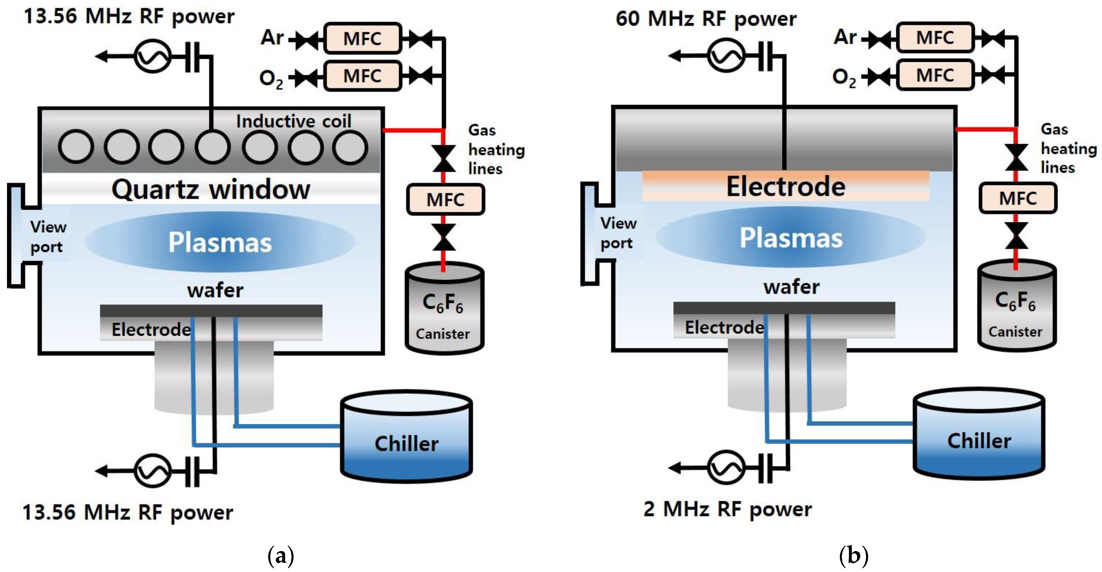
9] and applied using two different plasma etching systems, namely the capacitively coupled plasma (CCP) etching system and inductively coupled plasma (ICP) etching system.
The CCP system uses two facing electrodes, and multiple RF powers composed of high and low RF frequencies are generally applied to both the top and bottom electrodes or to the bottom electrode only; to provide ion energy to the substrate located at the bottom electrode, a lower frequency RF power is generally connected to the bottom electrode. Due to the electric field configuration of the CCP system, the CCP system tends to show a low plasma density of ~109–10/cm
3 and a low gas dissociation. In the case of the ICP system, one RF power is connected to the inductive antenna located at the top of the chamber for the generation of time-varying azimuthal electric fields in the process chamber for the high-density plasma formation of ~1010–11/cm
3 with a significant gas dissociation, and a low-frequency RF power is also connected to the bottom electrode to provide ion bombardment to the substrate [
10]. The ICP system is generally operated at a low pressure of a few millitorr, and etch rates are generally higher than those by the CCP system operated at a few tens of millitorr due to the higher ion flux and higher radical flux of the ICP system during the etching. However, for the high aspect ratio contact (HARC) etching of SiO
2 using perfluorocarbon (PFC)-based etch gases, even though the etch rates are slower than the ICP system, the CCP system is generally used due to the higher etch selectivity over mask layers caused by low dissociation of fluorocarbon gases at the lower plasma density in addition to the higher ion bombardment energy at the same low-frequency power to the substrate.
Previously, to obtain higher etch selectivity over mask layers in addition to high HARC SiO
2 etch rates, researchers have investigated using the ICP system instead of the CCP system for the HARC etching [
11,
12,
13,
14]. Li et al. used C
4F
6 gas for the etching of SiO
2 masked with photoresist in an ICP system, and even though the etch selectivity of SiO
2/PR was higher than conventional PFC gas of C
4F
8, the maximum etch selectivity was limited to 4 [
11]. Nakamura et al. also etched SiO
2 masked with photoresist in an ICP system with various PFC gases having different C/F ratios such as C
3F
6, C
4F
6, C
4F
8, and C
5F
8 and showed that the higher C/F ratio improved the etch selectivity but the maximum etch selectivity obtained with C
4F
6 was 2 [
12]. Kim et al. used hydrofluoroether-based gases in the etching of SiO
2 with an ICP system, but no etch selectivity data were provided [
13]. Therefore, even though studies have been carried out to etch SiO
2 selectively to mask layers using the ICP system, no sufficient investigation has been carried out and no results applicable to HARC SiO
2 etching have been reported.
During the etching of SiO
2 using the PFC gases, PFC gases are dissociated/ionized, and the characteristics of the dissociation/ionization affect the etch characteristics of SiO
2 such as etch rates, etch selectivity over mask layers, and etch profile. Because the characteristics of the dissociation/ionization of the PFCs by ICP and CCP systems are different, the HARC SiO
2 etch characteristics will be different; however, currently, no detailed research results can be found in the literature on the differences between the ICP system and the CCP system for the dissociation/ionization of PFCs and their relationship to the etching of HARC SiO
2 using the same PFC gases. Moreover, the reason for the use of the CCP system for the HARC etching instead of the ICP system is due to the lower dissociation of the fluorocarbon gas to have high C/F ratio radicals/ions in the plasma for the higher etch selectivity over mask layers, but no research has been carried out using a perfluorocarbon gas with the high C/F ratio ≥ 1.0 such as C
6F
6 for higher C/F ratio radicals/ions even for the higher gas dissociation. In this study, using a PFC gas having a high C/F ratio of C
6F
6, the differences in the plasma characteristics of the C
6F
6 and the etch characteristics such as etch rate, etch selectivity over a hard mask layer, and etch profile were compared between the ICP system and the CCP system. In addition, the possibility of using the ICP system in HARC SiO
2 etching masked with an amorphous carbon layer (ACL) was investigated. In the case of C
6F
6, in addition to a high C/F ratio, the global warming potential (GWP) is very low compared to some of PFC gases generally used for HARC SiO
2 etching such as CF
4 and C
4F
8 [
15,
16,
17], as shown in
Table 1, and its boiling point is lower than 0 °C (a liquid PFC); therefore, if required, the undissociated C
6F
6 can be collected at the exhaust line, which can reduce the global warming effect further.
3. Results and Discussion
Using C
6F
6/Ar/O
2, ACL-masked SiO
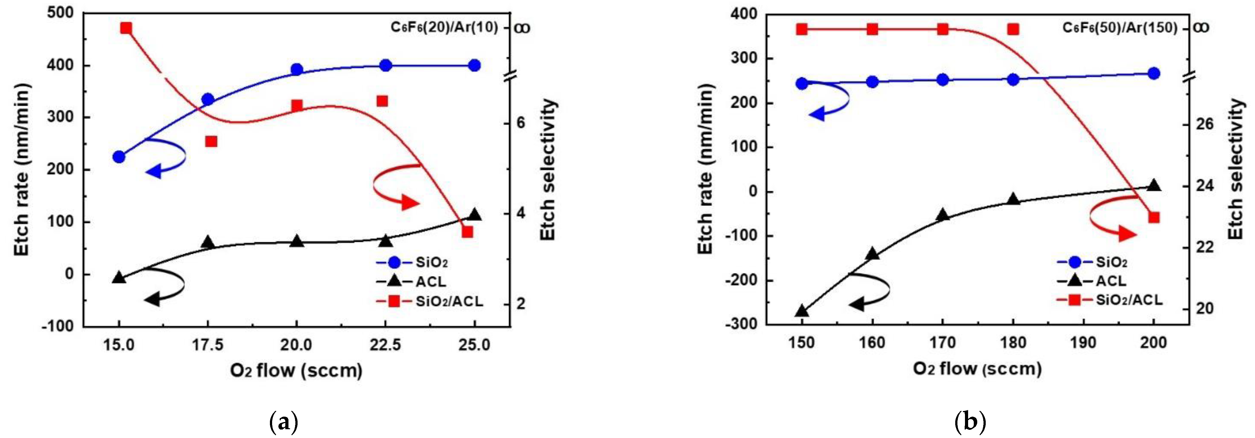
2 was etched in the ICP and CCP systems, and the etch rates and etch selectivities estimated from the etch depths of ACL and SiO
2 are shown in
Figure 2a for the ICP system and
Figure 2b for the CCP system. As shown in
Figure 2a, for the ICP system, until the oxygen flow rate was higher than 15.0 sccm, no etching of ACL was observed, and from the oxygen flow rate higher than 17.5 sccm, the ACL etch rate was increased with oxygen flow rate. In the case of SiO
2, the etching was observed even at 15.0 sccm, and with an increase in the oxygen flow rate, the SiO
2 etch rate was increased to ~400 nm/min at 20 sccm, and the further increase in oxygen flow rate nearly saturated the SiO
2 etch rate. The etch selectivity of SiO
2/ACL was infinite at 15 sccm and ~6.5 at 20–22.5 sccm, and the further increase in oxygen flow rate to 25 sccm decreased the etch selectivity to ~3.6. In the case of the CCP system, for the oxygen flow rate from 150 to 180 sccm, deposition of a fluorocarbon layer instead of etching was observed on the ACL, and when the oxygen flow rate was 200 sccm, ~12 nm/min of ACL etching was observed. In the case of SiO
2, the etch rate ~244 nm/min was observed even at 150 sccm; with increasing oxygen flow rates, the etch rate was slightly increased (or nearly saturated) to 200 sccm by showing the etch rate of ~267 nm/min. However, when the oxygen flow rate was lower than 150 sccm, SiO
2 etching was also decreased to ~0 for the CCP system (not shown). Therefore, the etch selectivity of SiO
2/ACL was infinite from 150 to 180 sccm, and the etch selectivity of ~23 could be obtained at 200 sccm. From the above results, it can be concluded that the etching of SiO
2 requires a much lower ratio of O
2/C
6F
6 (0.75–1.25 for ICP and 3–4 for CCP) for the ICP system, the maximum SiO
2 etch rate is higher for the ICP system (~400 nm/min for ICP and ~267 nm/min for CCP), and the etch selectivity is much higher for the CCP system at the maximum SiO
2 etch rate (~6.5 for ICP and ~23 for CCP).
To understand the differences in the etch characteristics of ACL-masked SiO
2 with C
6F
6/Ar/O
2 gas mixtures between the ICP and CCP systems, the dissociation characteristics of C
6F
6/Ar/O
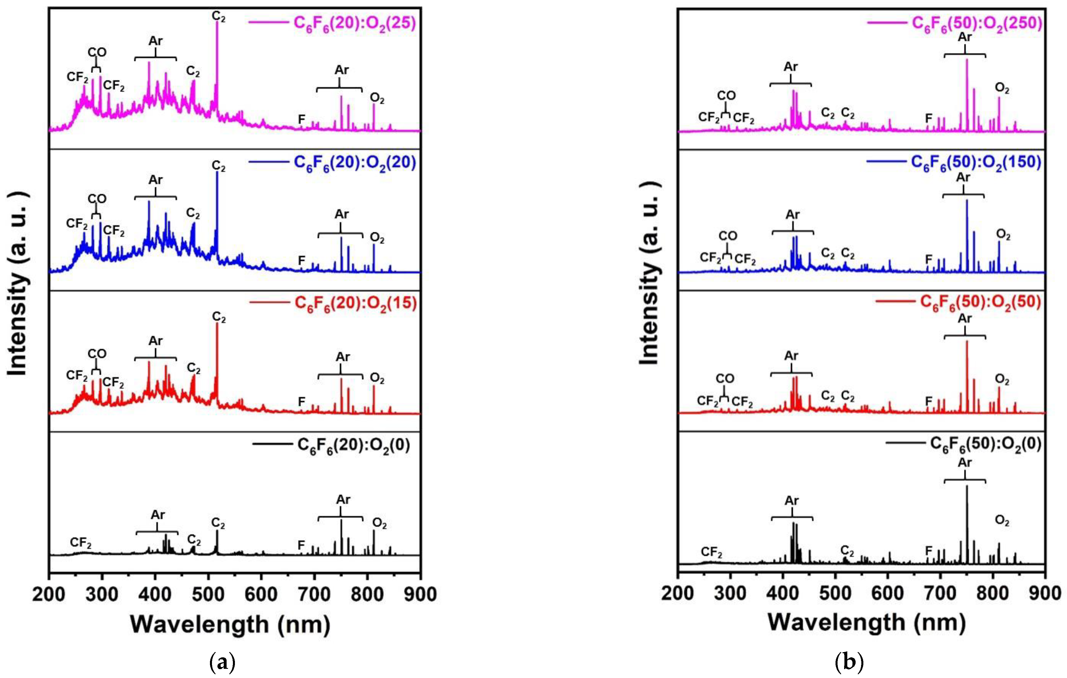
2 for different oxygen flow rates were investigated with OES for the wavelength range of 200–900 nm, and the results are shown in
Figure 3a for the ICP system from 0 to 25 sccm of oxygen flow rate and
Figure 3b for the CCP system from 0 to 250 sccm of oxygen flow rate. For easier comparison, the OES data were normalized by the Ar peak at 750.4 nm. As shown in
Figure 3a,b, optical emission peaks from O (777.3, 844.8 nm), F (685.7, 703.8 nm), Ar (696,7, 706.8, 738.6, 750.4, 772.5, 794.9, 800.7, 801.6, 811.6, and 826.5 nm), CO (282.7, 296.8 nm), C
2 (473.7, 516.7, 563.6 nm), CF
2 (245–321 nm), etc., could be observed [
19]. Among these peaks, the emission peaks related to CF
2 (247 nm), CO (297.7 nm), C
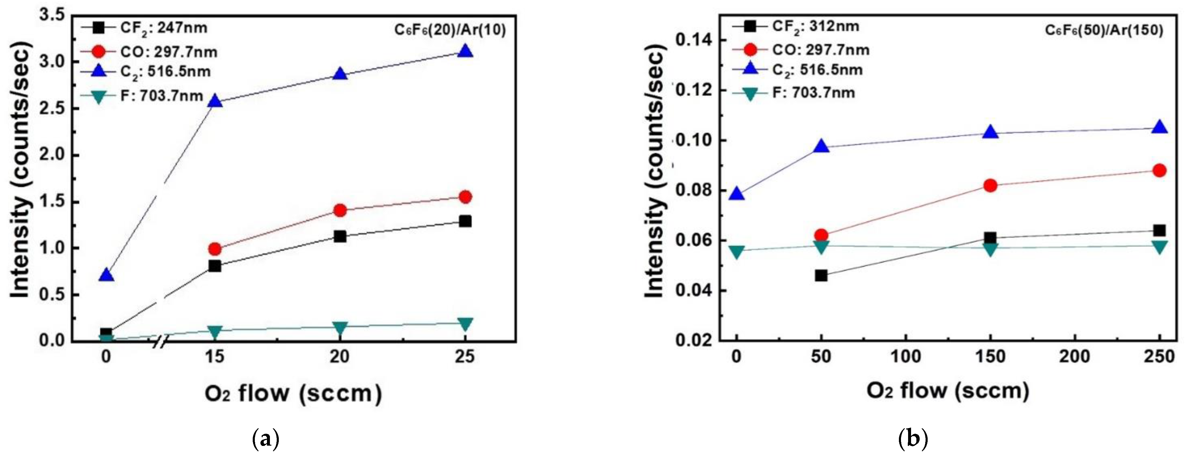
2 (516.5 nm), and F (703.7 nm) normalized by Ar (750. 4 nm) measured as a function of oxygen flow rate are shown in
Figure 4a for the ICP system and b for the CCP system. In general, during the etching of SiO
2 by fluorocarbon plasmas, F radicals react with Si on the SiO
2 surface and are removed from the surface as SiF
x while C radicals react with O on the SiO
2 surface and are removed from the surface as CO
x [
20]. As shown in
Figure 4a,b, the increase in densities of radicals such as CF
2, CO, C
2, and F with increasing oxygen flow rate could be observed in both the ICP system and the CCP system due to the increased dissociation of fluorocarbon by oxygen radicals in the plasmas. However, a more significant increase in the radicals with increasing oxygen flow rate was observed for the ICP system even with lower oxygen flow rates. When the radical ratios of CF
2/F, CO/F, and C
2/F were compared between the ICP and CCP systems, significantly high ratios of CF
2/F (5.0–7.1 for ICP and 0.8–1.1 for CCP), CO/F (0–8.8 for ICP and 0–1.5 for CCP), and C
2/F (15.5–41.5 for ICP and 1.4–1.8 for CCP) were observed for the ICP system due to the significantly higher radical densities of CF
2, CO, and C
2 compared to F density for the ICP system, indicating more significant dissociation of the C
6F
6 of the ICP system compared to the CCP system.
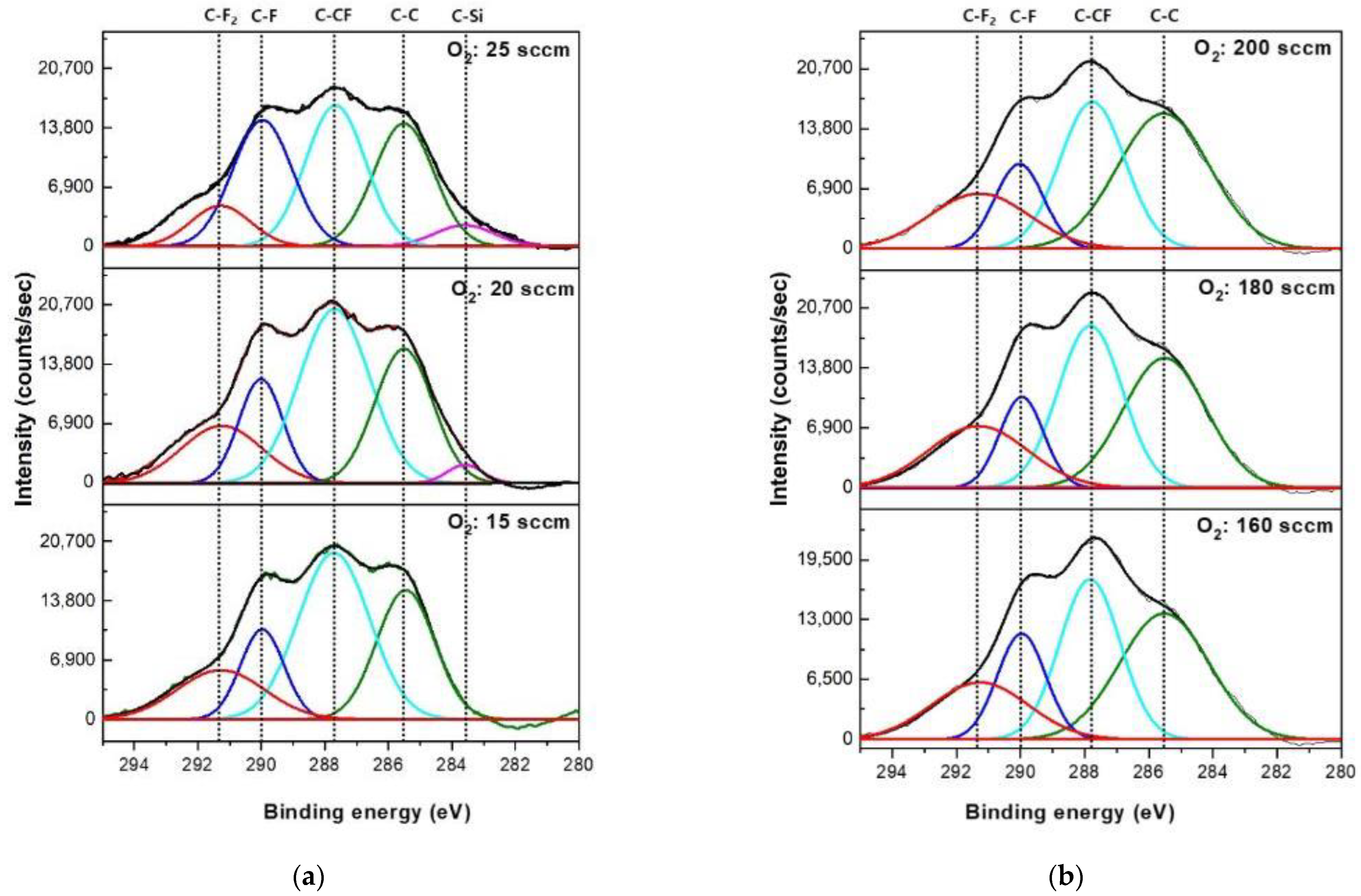
Figure 5 shows the XPS narrow scan data of C 1s on the SiO
2 surfaces etched with C
6F
6/Ar/O
2 for different oxygen flow rates for (a) the ICP system with C
6F
6(20)/Ar(10)/O
2 (15–25 sccm) and (b) the CCP system with C
6F
6(50)/Ar(150)/O
2(160~200 sccm). The other conditions are the same as those in
Figure 2. The carbon bonding peaks such as C–C (285.5 eV), C–CF (287.8 eV), C–F (290.0 eV), and C–F
2 (291.3 eV) could be observed [
21]. For the ICP system, as shown in
Figure 5a, the increase in oxygen flow rate from 15 to 25 sccm decreased C–C bonding and C–CF bonding slightly possibly due to the greater dissociation of species from the plasmas as shown in
Figure 4a. In the case of the CCP system, the increase in oxygen flow rate from 160 to 200 sccm did not change the carbon bonding peaks on the SiO
2 surface noticeably possibly due to no significant change of radical ratios with increasing oxygen flow rate as shown in
Figure 4b. When C 1s bonding peaks on the etched SiO
2 surfaces between the ICP system and the CCP systems are compared, the SiO
2 surfaces etched by the CCP system show slightly higher C-CF bonding intensities compared to those by the ICP system.
Table 2 shows the composition of the SiO
2 surface etched using C
6F
6/Ar/O
2 as a function of O
2 gas flow rates for the ICP and CCP systems for the conditions in
Figure 5. As shown in
Table 2, even though the ratio of C
6F
6/O
2 in the gas mixture was much higher for the SiO
2 etching using the CCP system, similar compositions of fluorocarbon polymer layers were observed between the ICP system and the CCP system on the etched SiO
2 surfaces; however, a more significant increase in Si percentage (0% to 2.5% for ICP and 0% to 0.7% for CCP) and a more significant decrease in C percentage (48.6% to 42.6% for ICP and 47.8% to 45.7% for CCP) were observed on the etched SiO
2 surfaces for the ICP system compared to those for the CCP system, indicating thinner fluorocarbon layers on the SiO
2 surface etched by the ICP system, which could increase SiO
2 etch rate with increasing oxygen flow rate. In fact, the SiO
2 etch rate was increased with oxygen flow rate from 15 to 22.5 sccm for the ICP system, while that for the CCP system was almost saturated with increasing oxygen flow rate from 150 to 200 sccm.
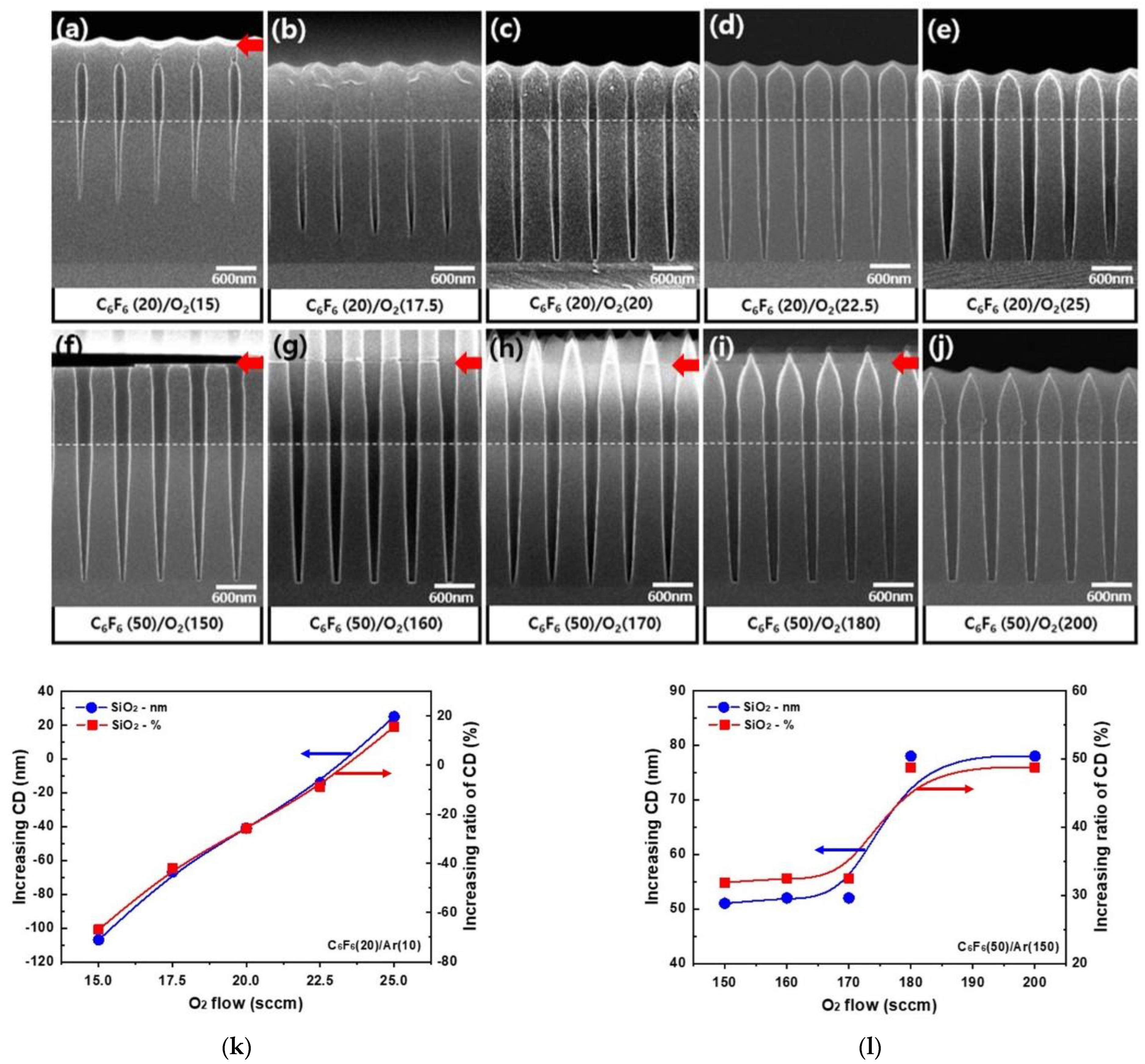
The etch profiles of 160 nm ACL hole masked SiO
2 with different O
2 gas flow rates of C
6F
6(20)/Ar(10)/O
2(15–25 sccm) for the ICP system are shown in
Figure 6a–e, and those with C
6F
6(50)/Ar(150)/O
2(150–200 sccm) for the CCP system are shown in
Figure 6f–j. White dotted lines are the ACL mask bottom positions and red arrows show ACL mask top positions. For the ICP etching with C
6F
6/Ar/O
2, for 15–17.5 sccm of oxygen flow rate, the ACL mask was clogged by the fluorocarbon layer after etching 1.4–2.0 μm depth of SiO
2. After using the oxygen flow rate of 20 sccm or higher, ~2.4 μm thick SiO
2 could be fully etched with highly anisotropic etch profiles even though the etched amount of ACL mask was increased with the increase in oxygen flow rate. In the case of the CCP etching with C
6F
6/Ar/O
2, for the oxygen flow rates of 150–180 sccm, a thick fluorocarbon layer was deposited on the top of the ACL mask while etching ~2.4 μm thick SiO
2 anisotropically; therefore, infinite etch selectivity of SiO
2/ACL could be obtained. For the oxygen flow rate of 200 sccm, the top of the ACL mask was etched while etching ~2.4 μm thick SiO
2. Therefore, as shown in
Figure 2b, the infinite etch selectivity of SiO
2/ACL was observed for the oxygen flow rate of 150–180 sccm, and the etch selectivity of 23 was observed for the oxygen flow rate of 200 sccm. However, for the SiO
2 etching with the CCP system, even though deposition of a fluorocarbon layer on the top of the ACL was observed during the etching of SiO
2, the ACL sidewall was etched for the oxygen flow rates of 150–180 sccm; therefore, triangular-shaped ACL was observed after the etching.
The changes of SiO
2 hole diameter critical dimension (CD) and its changed percentages after the etching of ~2.4 μm thick SiO
2 on Si masked by 1.4 μm thick ACL with 160 nm hole patterns for
Figure 6a–e the ICP system and
Figure 6f–j the CCP system were showed in
Figure 6k,l, respectively, except for the cases when the ACL mask holes were clogged by a fluorocarbon layer. As shown in
Figure 6k, for the ICP system, due to the clogging of the ACL mask top area at the lower oxygen flow rates, the hole pattern diameter smaller than the ACL mask hole diameter was observed for the oxygen flow rate from 15 to 20 sccm (from −66% at 15 sccm to −25% at 20 sccm), but due to the increase in hole diameter with increasing oxygen flow rate, the hole diameter equal to the ACL mask hole diameter CD or higher was observed with the further increase in oxygen flow rate from 22.5 to 25 sccm (from −8% at 22.5 sccm to +15% at 25 sccm). Therefore, for the oxygen flow rate of 20~22.5 sccm, highly anisotropic SiO
2 etch profiles with no significant hole diameter CD variation were observed for the etching by the ICP system with C
6F
6/Ar/O
2, which could be applied for the HARC SiO
2 etching. However, as shown in
Figure 6l, for the etching by the CCP system with C
6F
6/Ar/O
2, even though the etch selectivity of SiO
2/ACL was infinite, due to the etching of ACL sidewall, for the oxygen flow rates of 150~200 sccm, an increase in hole diameter percentage from +31% to +48% was observed with less anisotropic SiO
2 etch profiles compared to those etched by the ICP system.
For the CCP system, the ratio of Ar/C
6F
6 used in the etching of ACL-masked SiO
2 was much higher than that for the ICP system (10/20 for ICP and 150/50 for CCP); therefore, the widening of the SiO
2 hole diameter CD could be related to the enhanced ion bombardment by Ar
+ ions for the CCP system. In fact, in the experiment, the different Ar flow rates used for the ICP and CCP systems were related to the optimized process for the SiO
2 etching with the ICP and CCP systems. However, to clearly show the effect of Ar gas flow rate on the etching, the SiO
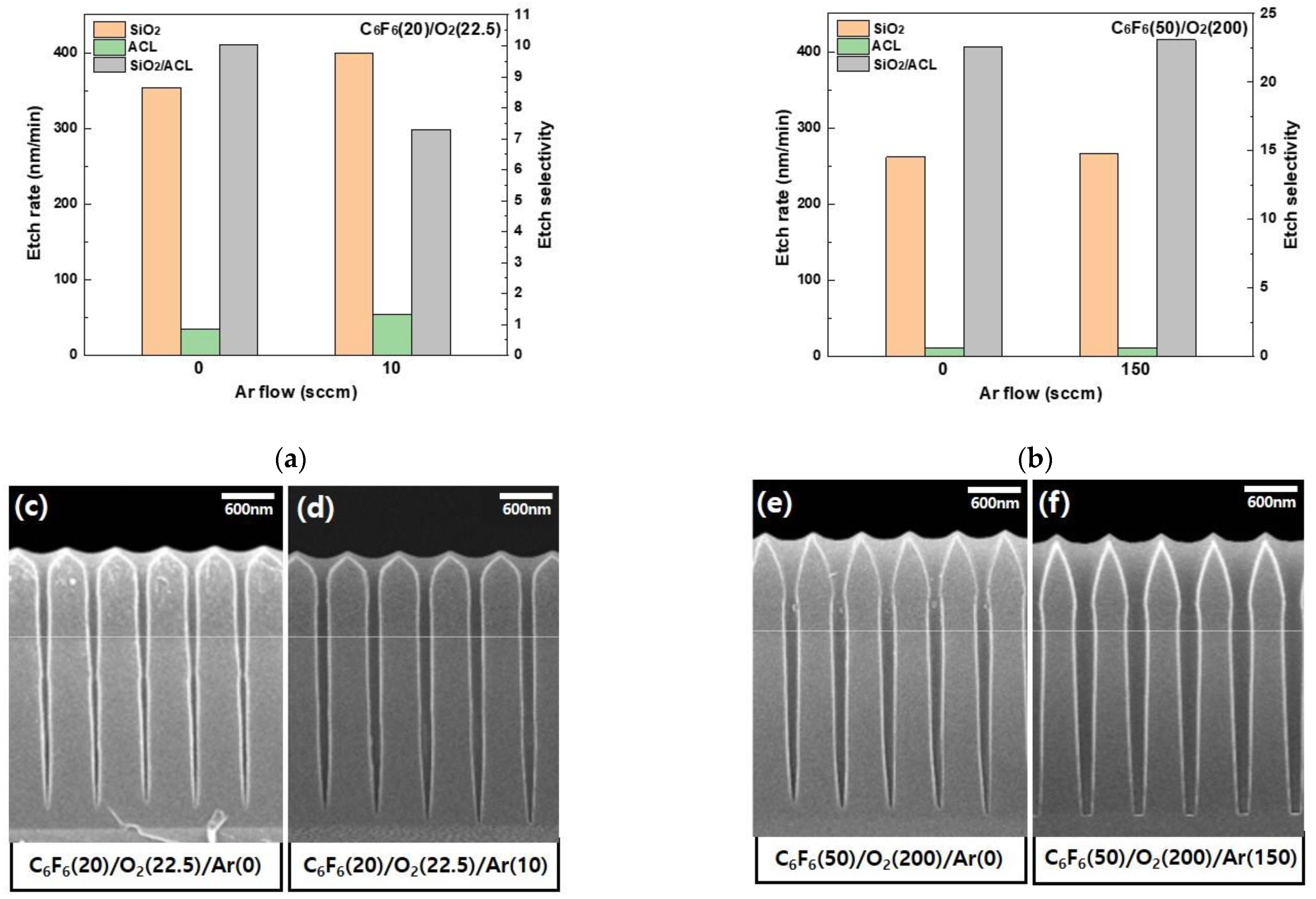
2 masked by ACL mask was also etched with and without the Ar flow rates for each of the ICP/CCP etching conditions.
Figure 7 shows the etch rates of SiO
2 and ACL and the etch selectivity of SiO
2/ACL for (a) the ICP system and (b) the CCP system with and without Ar flow in C
6F
6/Ar/O
2. (c) and (d) are the SEM etch profiles of ACL-masked SiO
2 with and without Ar flow for the ICP etching, respectively, and (e) and (f) are those with and without Ar flow for the CCP etching, respectively. The gas mixtures of C
6F
6(20)/Ar(0)/O
2(22.5) and C
6F
6(20)/Ar(10)/O
2(22.5) were used for the ICP etching, and the gas mixtures of C
6F
6(50)/Ar(0)/O2(200) and C
6F
6(50)/Ar(150)/O2(200) were used for the CCP etching. As shown in
Figure 7, the etch rates of SiO
2 and the etch selectivities of SiO
2/ACL were not significantly different for the etching with and without Ar flow for both the ICP system and the CCP system. In fact, there were some differences in the SiO
2 etch profiles between the gas mixtures with and without Ar, as shown in
Figure 7c–f; however, also, no significant differences could be observed. Therefore, the more significant etching of the ACL sidewall and the more significant widening of SiO
2 hole diameter for the CCP system with C
6F
6/Ar/O
2 are not related to the higher Ar+ ion bombardment flux to the substrate due to the higher Ar gas flow rate in the gas mixture. In fact, in the case of the CCP etching, due to the low dissociation of C
6F
6, higher-mass ions such as C
xF
y+ (x = 3–6, y = 4–5) having the ion mass higher than 100 (while the mass of Ar+ is ~40) can exist in the plasmas more than those formed during the ICP etching. The ion bombardment by those partially dissociated high-mass ions can etch the ACL sidewall more and widen the SiO
2 hole diameter more, which can result in more tapered etch profiles as shown in
Figure 6f–j.


