Article

An Analysis of Electromagnetic Disturbances from an Electric Vehicle Charging Station

Department of Electrical Engineering and Electrotechnologies, Lublin University of Technology, Nadbystrzycka 38 A, 20-618 Lublin, Poland
*
Author to whom correspondence should be addressed.
Energies 2022, 15(1), 244; https://doi.org/10.3390/en15010244
Submission received: 11 November 2021 / Revised: 21 December 2021 / Accepted: 28 December 2021 / Published: 30 December 2021
(This article belongs to the Special Issue Power Electronics in Renewable, Storage, and Charging Systems)

Abstract

:
The electric vehicles (EVs) could potentially have a significant impact on power quality parameters and distribution networks as they are non-linear loads and their charging might result in tremendous power demand. When connected to the utility grid, a large number of EV charging stations from different manufacturers might create significant harmonic current emissions, impact the voltage profile, and eventually affect the power quality. Nevertheless, practical examples of disturbances from charging stations have not been made public. This paper aims to clarify the characteristics of conductive disturbances and levels of current harmonics generated by charging station and their severity on the quality of electric energy. The analysis was based on tests of a prototype station of an EV charging station integrated with a LED street light. The tests concern the determination of current harmonics and the values of conductive electromagnetic disturbances in the 150 kHz–30 MHz range. The test results of the prototype charger with observed exceedances of current harmonics (25th–39th range) and conducted interference exceedances are comprehensively described. After applying filtering circuits to the final version of the station, retesting in an accredited laboratory showed qualitative compliance.

1. Introduction

Conventional transportation modes need alternatives, necessitated by fluctuating oil prices, high dependence on imported fossil fuels, and commitments to the reduction in greenhouse gas emissions [1,2,3]. An increasingly significant role is played by EVs, which are constantly developing. This is due to the persistent need for longer drive ranges to be covered, battery charging time to be reduced, and energy efficiency to be improved. These operations are focused on smart charging control systems, reduction in manufacturing costs, and new safety and security technologies for EV owners [4].
Over the last few years, the amount of publicly available EV charging stations has significantly increased. The latest report of International Energy Agency [5] shows that the global number of EVs has increased to more than 10 million in 2020 (i.e., a 1% share in global transport). The People’s Republic of China accounted for two thirds of all new EV registrations that year.
The EV charging infrastructure also continues to develop. In 2020, the number of publicly accessible chargers reached more than 1.3 million of which 922,216 (70.5%) were slow chargers and 385,678 (29.5%) were fast-charging [6]. EV owners usually prefer to charge their EVs at their homes and workplaces in many EV markets. The availability of EV charging at home is closely related to population density, number of apartments with a garage or parking space, and local EV ownership rates. It is difficult to accurately estimate the number of private chargers as a compatible electrical outlet: an appropriate cable and plug are needed to charge a vehicle at home. Convenience, cost effectiveness, and different support policies are factors that make private charging points the most popular. The report Global EV Outlook 2020 [7] shows that there were 6.5 million private charging points in 2019.
In September 2021, according to the Electromobility Counter [8] that has been established by the Polish Alternative Fuels Association and the Polish Automotive Association, in Poland, there were:
  • 31,633 EVs (15,255 battery EVs and 16,376 plug-in hybrid EVs), and
  • 1675 public charging points (1159 AC type and 516 DC type).
In 2020, there was a more than 50% increase in EVs registered in Poland compared to the previous year. The situation related to the COVID-19 pandemic might break the growing trend. On 16 June 2020, the Ministry of Climate and the National Fund for Environmental Protection and Water Management released information about three schemes called Hummingbird, eVAN, and Green Car, addressed at different beneficiaries to stimulate the development of electromobility [9]. A total of PLN 150 million was allocated for this purpose. However, the programs were not popular among Polish citizens [10].
Power quality parameters are influenced by the non-linear current consumption of some loads. The development in the field of electronics and power engineering have affected the introduction of a growing number of non-linear energy receivers to the market. These are sources of harmonic distortions of supply current and supply voltage. Examples of the simplest non-linear receivers are converters, inverters, switching power supplies and receivers using electrical discharges in gas such as arc welders or gas-discharge lamps [11,12,13,14].
For the reason that the EV charging process might have an influence on the grid, charging techniques should adhere to the network code of the operator of the system. Load profile, energy pricing, increased demand, power quality, grid congestion, and voltage stress are some of these issues [15]. The impact of EV charging on distribution system operator networks is influenced by a variety of parameters including the number of EVs being charged at the same time, the charging pattern, coordination, location of the EV chargers, charging rate, and time of the charging [16]. The influence of e-bus integration on the grid was investigated in [15], and voltage regulation, harmonic distortion levels, unbalances, extra losses, and transformer life-time loss are all topics to consider when analyzing the effects of EV charging on distribution networks. Due to the fact that a distributed system entails a more horizontally structured grid in terms of power quality, the effects of harmonics have become important to investigate [17]. The influence of EVs on power quality has been reported in a variety of ways in the literature. Authors of low-voltage systems simulations [18], especially in urban situations [15,19], argue that distribution networks might have constraints in EV charging assistance and EV harmonics analysis even at low levels of EV penetration [20,21]. The effects of residential EV harmonic current emissions on the power losses and aging of EV interfacing transformers were studied in [22]. Other research [23,24,25] implies that with normal charging power, low plug-in electric vehicle penetration levels would have tolerable low harmonic levels and voltage swings, while fast-charging might result in considerable voltage harmonics as well as power losses [26]. Studies [27,28] have also focused on the harmonic aspects of EV penetration. The impact of EV integration on power losses has been studied extensively [29,30,31]. Authors in [32,33] demonstrated that a large penetration of electric vehicles combined with unregulated EV charging might cause power losses in distribution networks. According to Masoum et al. [34], integrating EVs might cause a distribution transformer’s power losses to rise by up to three times for a large number of EVs. Random EV charging, according to Deilami et al. [35], might deviate from the voltage harmonic’s standard level. Most studies have concentrated solely on current harmonics emissions, addressing the primary problem of home EV charges, which are projected to have a larger penetration. The authors in [36] discuss the emission and propagation of supraharmonics from individual and combinations of EVs on a low-voltage grid as well as a study of hypothetical supraharmonic interactions between EVs.
The charging process of EV is complex. The impact of EV charging on the power system is defined by its power quality parameters. EV chargers convert alternating current to direct current from the power system to recharge on-board batteries. Non-linear power electronic devices are used in EV chargers. Typical system structures use an AC/DC/DC/AC intermediate processing, high-frequency transformer, and AC/DC final straightening. The use of diodes and switches in power converters, which are an integral part of EV chargers, contributes to current distortion. With a large number of such types of stations, exceeded voltage harmonics might be observed [37,38,39,40,41,42,43]. The solution may be systems with input rectification based on a transistor-controlled system or other topologies [25,44,45,46]. Such systems will be compatible with bi-directional energy transfer technologies (vehicle-to-grid concept).
During the operation of an EV charger, harmonics are fed into the grid, which can worsen power quality parameters. The harmonic emissions of EVs depends on the circuit design, the control algorithm of the charger as well as the voltage distortion, but can also be influenced by other EVs and/or non-linear loads. The effects of current harmonic distortions include overheating of neutral wires (summation of odd multiples of the 3rd harmonic), overheating of transformers (losses in eddy currents and 3rd order harmonics), undesirable tripping of circuit breakers, or a skin effect, resulting in increased heat generation and the need for additional cable oversizing, damage to generators and turbine shafts, protection malfunctions, capacitor overloading, motor overheating, system resonances, and the flicker phenomenon (light intensity change), which is one of the most easily observed effects of the presence of harmonics [39,46,47,48,49,50,51]. As a result, in order to characterize the quality of the power delivered, it is necessary to measure the harmonics. Total harmonic distortion (THD) is one of the most significant measurement indices used to systematically and comparably evaluate power quality, hence assisting in the improvement of power system quality and reduction in distortion levels. Because the basic component is usually the dominant one in power systems, notably for voltage, THD denotes the proportion of signal energy difference from it [52,53].
The current total harmonic distortion (THDI) can be calculated according to the formula:
THD I = h = 2 I h 2 I 1 × 100 %
where Ih is the RMS value of the individual harmonic component of order h for current, and I1 is the RMS value of the fundamental harmonic (a component of order 1) for current.
Electric vehicle (EV) chargers are a modern and atypical load that must be treated as a new customer by power distribution systems. The increasing number of EVs and EV chargers that connect to the power grid entails many new challenges and complications. The individual behavior of EV owners varies greatly. This randomness of EV charging makes it difficult to keep the power grid under control and may have a negative impact on the overall operation of the power grid. Thus, important issues for the power quality in the power system are conductive electromagnetic disturbances and current harmonics. Electromagnetic compatibility (EMC) analyses ensure that the designed object complies with the standards and will not interfere with the operation of other electrical equipment and the power system [37,38,54,55]. Figure 1 presents typical impacts of electric vehicles on power quality.
Standards used for preventing harmonics from affecting the power grid are, for instance, IEC 61000-3-12/2-4 [56]. These standards are advocated with the goal of providing recommended methods and regulations that allow for harmonic emission control in electrical power systems [17].
The standards above-mentioned, which have been approved by both academia and industry, outline the difficulties that harmonic current distortion may pose in electrical systems as well as the limitations of such harmonics in a specific system. In IEC 61000-3-12 [56], the table contains the limits as a percentage of the reference current. The restrictions set forth in this International Standard apply to electrical and electronic equipment having a rated input current more than 16 A and up to and including 75 A per phase, which is intended for use in public low-voltage AC distribution systems.
In both public low-voltage and medium-voltage electricity distribution networks, the European Norm EN 50160 specifies the principal voltage characteristics and their acceptable deviation ranges at the customer’s Point of Common Coupling (PCC). It describes the limits and values for which the voltage properties are expected to be preserved within the entire public network.
Issues related to the measurement of conductive disturbances from charging stations are not covered in depth in the literature. The standards IEC 61851-21-1 and IEC 61851-21-2 regulate EMC test procedures of on-board and off-board EV chargers, respectively. EMC pre-compliance test procedures are considered for either the charging station or the vehicle alone, but not for the two together.
To the authors’ knowledge, there are only a few papers addressing EMC testing of EV chargers or components of the EV charger [57,58,59,60,61]. Information in the paper is significant because electromagnetic compatibility testing of the EV charger, especially integrated with a LED street light, along with the measurement of harmonic current emissions, is not a popular subject among researchers.
This paper is organized as follows. In the introduction, theoretical background of the harmonics and the standards is given. Next, a unique bidirectional charging station integrated with street lighting is described. Section 2 also describes the measurement systems for measuring harmonics and conducted electromagnetic disturbances. The results of the obtained tests are presented in Section 3. The authors, investigating the influence of the EV charger on the power system, atypically combined the tests of two factors—current harmonics and conducted electromagnetic disturbance. The steps of building the charger are also described—in the first analysis, too much electromagnetic interference was measured and the filtering circuit had to be customized. The analysis of all measurement results is described in Section 3. Section 4 concludes with a summary of the findings and the most relevant conclusions.

2. Materials and Methods

The object analyzed was a charging station. As part of the project POIR.04.01.02-00-0052/16 “Electric vehicle charging system integrated with lighting infrastructure”, carried out in a consortium of the Lublin University of Technology and PGE Dystrybucja S.A., a prototype energy transfer station PLUGinEV was created. The station is characterized by bidirectional operation, the power of 22.7 kW, and the possibility of charging vehicles with DC and AC current (DC voltage 300 V–450 V, SAE CCS connector type 2; AC voltage 3 × 400 V, 50 Hz, SAE IEC 62196 connector type 2) [62]. The three-phase station for bidirectional fast energy transfer between the power grid and an electric vehicle contains two modules, AC and DC, and is integrated with a LED street lamp (Figure 2).
Charging stations or charging points are part of the road public transport charging infrastructure. They must therefore meet the technical and operational requirements set out in the national standards. Measures to ensure the electromagnetic compatibility of vehicle charging stations are necessary for safe use. The measurements of the EV charging station were divided into two parts.

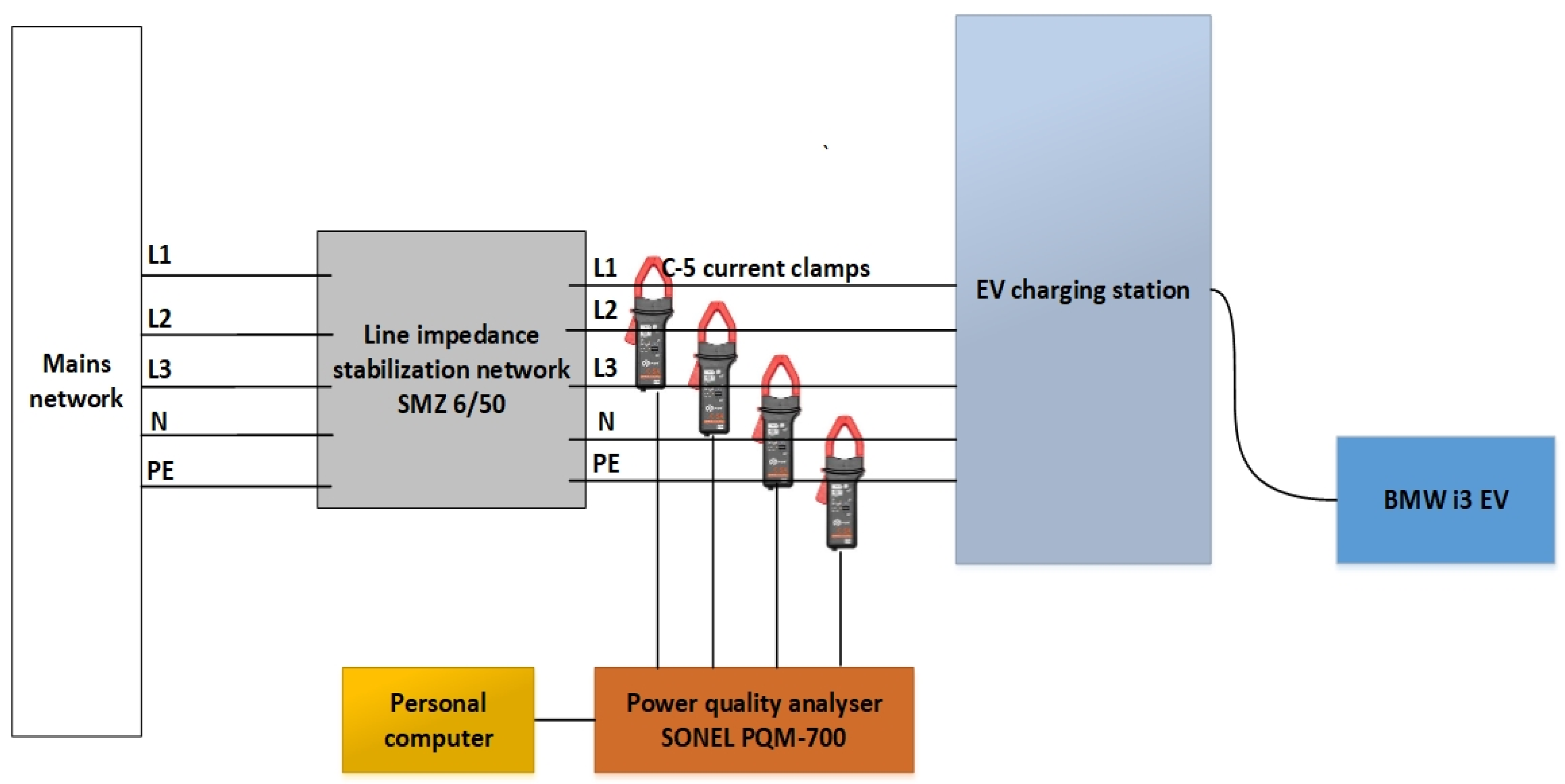
2.1. Harmonic Current Emission Measurements

Initial measurements were focused on the test of the EV charger’s AC module and took place in a non-accredited laboratory of the Lublin University of Technology. The research involved harmonic current emission measurements during the operation of the EV charging station to which a BMW i3 EV was connected (Figure 2a). The initial state of charge of the vehicle was 30% (total battery capacity: 60 Ah, declared range of 100 km). The EV was equipped with a CCS plug. Type 2 plug was used for slow charging (charging current: approximately 14 A). The output voltage of each phase was 230 V (50 Hz).
Preliminary harmonic current emissions were measured with the Sonel PQM-700 power quality analyzer. This device measures and records power quality parameters in accordance with the IEC 61000-4-30 class S standard. The measurements were performed with the use of four C-5 current clamps (a possibility of AC and DC current measurement). The EV charging station was connected to a three-phase line impedance stabilization network (LISN) INCO SMZ-6/50. The analyzer was connected to a personal computer. The read-out mode was used. Figure 3 shows a laboratory setup for harmonic current emissions.
Final measurements of harmonic emissions were realized in an accredited EMC laboratory at the Wroclaw University of Technology. Measurements of harmonic current emission were carried out on the test setup shown in Figure 4, arranged in accordance to standard requirements [56,63]. The EV charging station was connected directly to the socket of reference impedance. The impedance was configured in bypass mode.

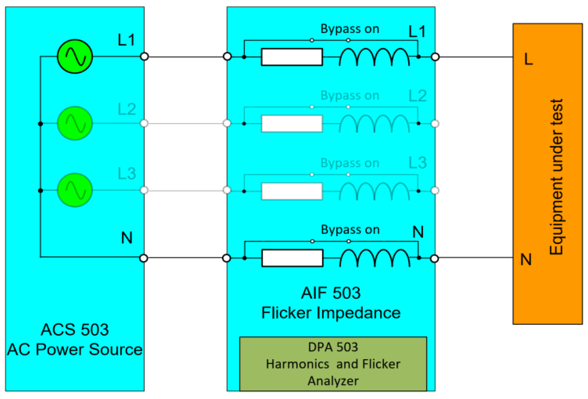
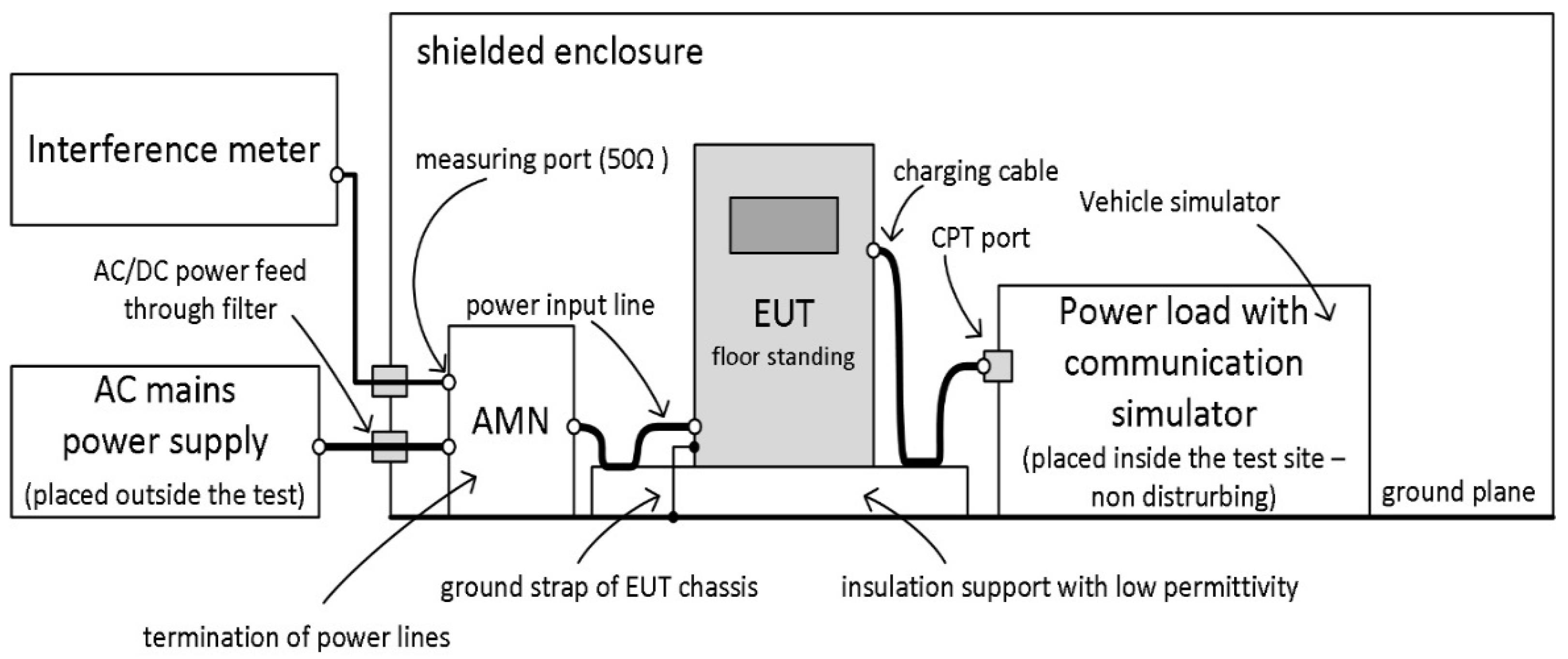
2.2. Measurements of Conductive Electromagnetic Disturbances

The electromagnetic compatibility analysis of the charging station was regulated by the procedures of the EMC Directive 2014/30/EU. In the field of conductive disturbance emission, the permissible limits are specified in the IEC 61851-21-2 standard [64]. Conductive disturbances in the 150 kHz–30 MHz band must be analyzed. The tests were carried out in a system consisting of a measuring receiver, an artificial network (AMN) in the power supply line, and a charging station loaded with a resistance, symmetrical simulator (a 120 kW water-cooled resistive). Figure 5 presents the diagram of the system used in the study. The measurements of conductive disturbances were carried out in two modes of charger operation for 20% and 80% of the power transferred by the station.
The operating modes result from the various legal recommendations that define the safety of charging electric vehicles. Instead of an EV, a 120 kW water-cooled (3-phase) resistive load was used for the measurements. Resistive loads are essential instruments for simulating the load devices that will be present in power systems.

3. Results and Discussion

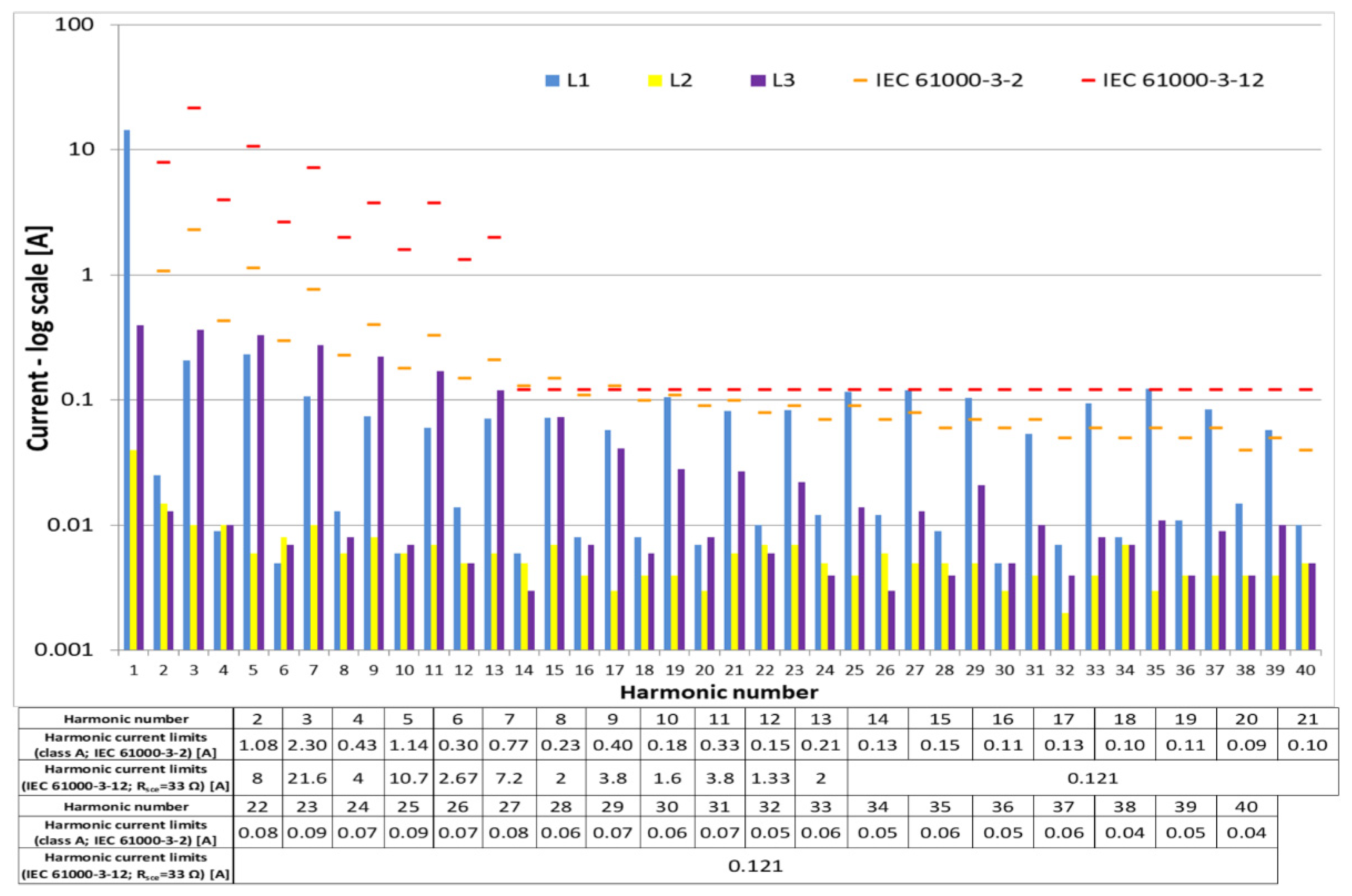
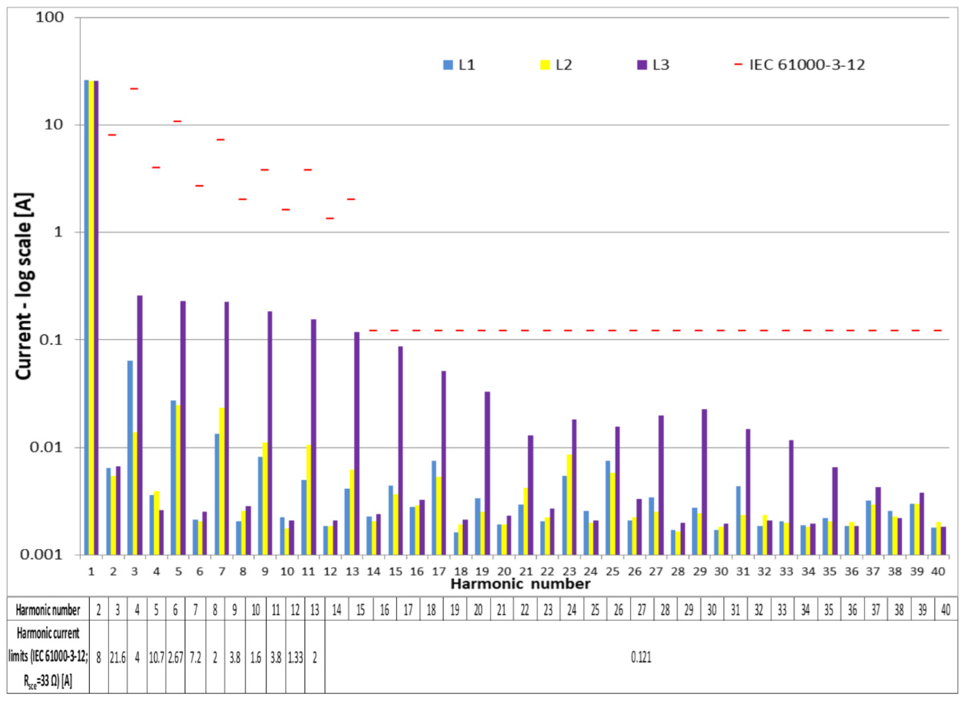
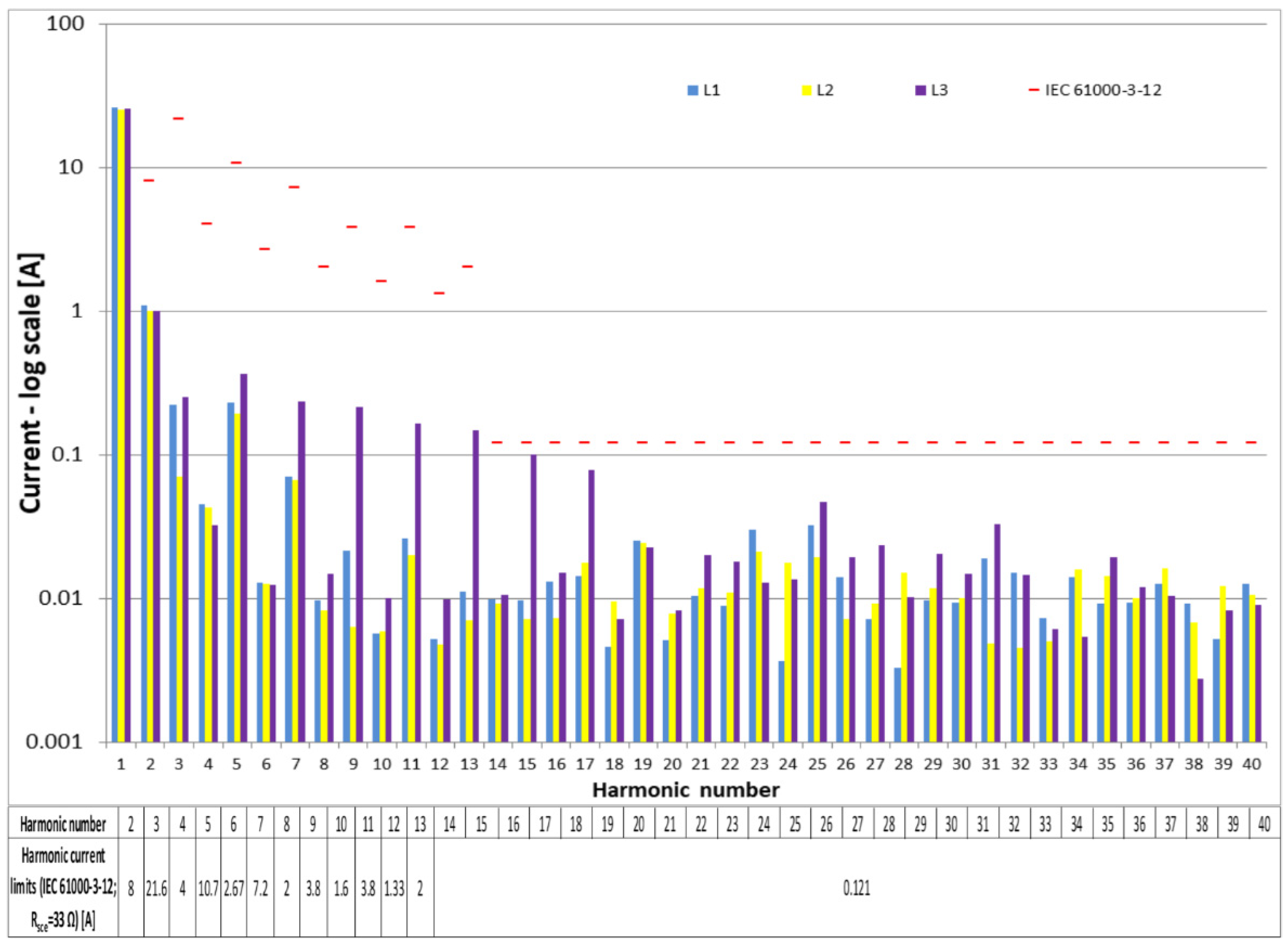
3.1. Harmonic Current Emissions

A presentation is made of the first results of the electric current harmonics measurements performed in a laboratory at the Lublin University of Technology with a vehicle connected to the charging station. The results of current harmonic measurements for each phase and a neutral conductor are compared with the limits defined in IEC 61000-3-2 for Class A devices. This is shown in Figure 6. The choice of the standard limit is due to the car charging system used. The on-board battery charging control system of the car was set to values below 16 A, and this means that the limits of IEC 61000-3-2 have to be applied [24]. The limits of IEC 61000-3-12 are for currents up to 75 A [56,65].
As can be seen in Figure 6, the 25th, 27th, 29th, 33rd, 35th, 37th, and 39th harmonic currents of phase one slightly exceeded the limit given in the IEC 61000-3-2 standard. With respect to the IEC 61000-3-12 industry standard, these levels are acceptable. Such a slight exceedance might result from the class of the analyzer used (class S). Nevertheless, the identified current harmonics during car charging is a factor affecting the power quality of the power system.
After applying filter circuits to the prototype charger, more accurate measurements were made in an accredited EMC Laboratory of the Wrocław University of Technology. The next graphs (Figure 7 and Figure 8) illustrate the forty current harmonic emissions measured in the aforementioned laboratory. The harmonic current spectrum refers to the testing of the EV rectifier’s AC module and DC module (80% of power) loaded with a resistance simulator. Measurements during the operation of the AC module and then the DC module of the EV charger showed that the harmonic currents meet the requirements of the IEC 61000-3-12 standard. Measurements were performed for higher charging currents, but the receiver of the charging station was not the car battery but a resistive simulator (standards compliant system). The results from the accredited EMC laboratory showed a negligible emission of harmonic current during charging, which did not significantly affect the operation of the power system. Results presented in Figure 7 and Figure 8 indicate high levels of current harmonics although within the permissible limit of IEC 61000-3-12. At the same time, higher levels of all current harmonics were found during the DC module operation compared to the AC module operation.
The calculated values of current total harmonic distortion (THDI) are presented in Table 1. All values of THDI were within the permissible range of the IEC 61000-3-12 standard. The highest values were observed during AC module operation. This might be a result of the operation of the bidirectional isolated DC/DC converter with dual active bridge topology implemented in the charger.
The actual harmonic results presented are comparable with those conducted by other authors [66,67,68]. As it is an initial study of research, based mainly on the analysis of the operation of a single charger, the authors did not extend to large-scale analyses that aimed to evaluate the impact of the control algorithm of the charger and/or non-linear loads on the distribution grid.

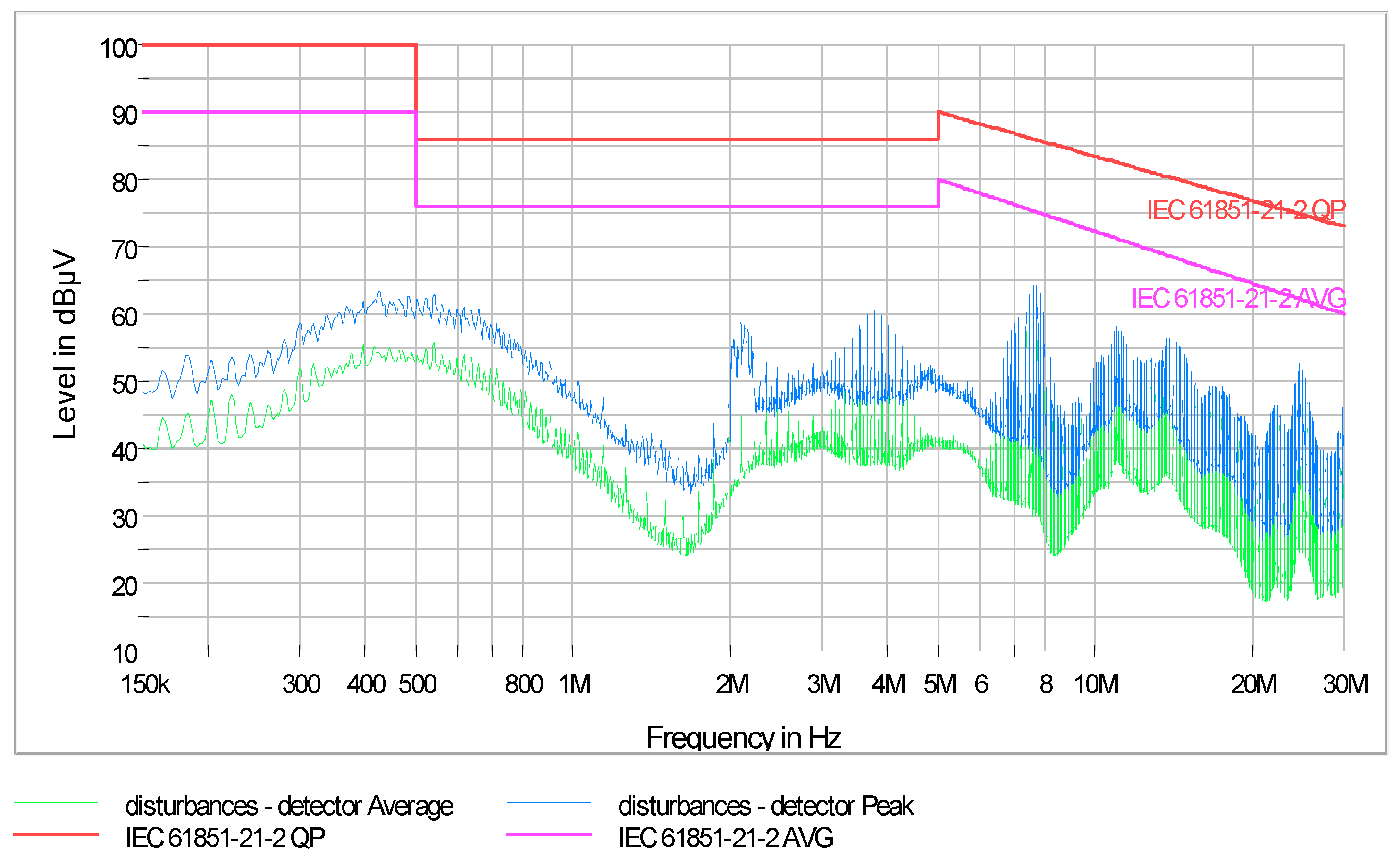
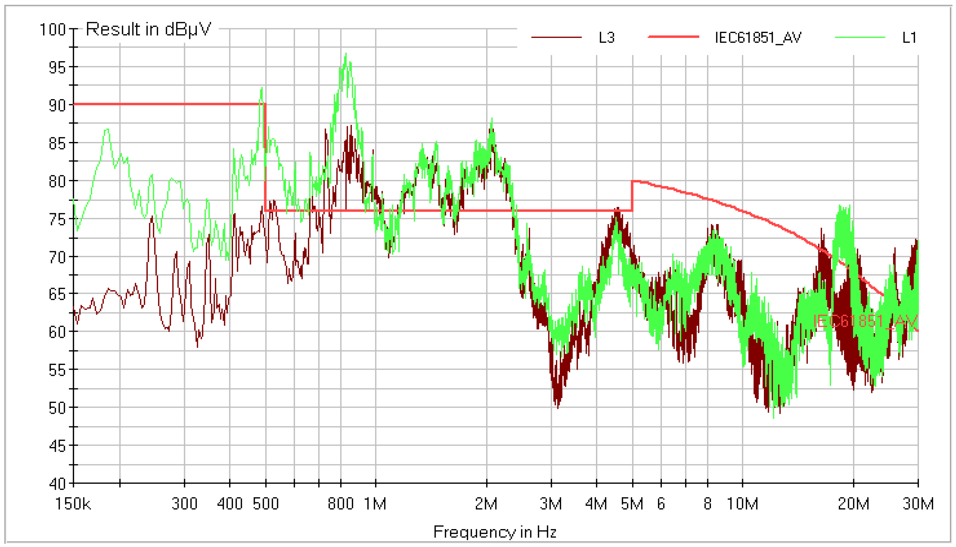
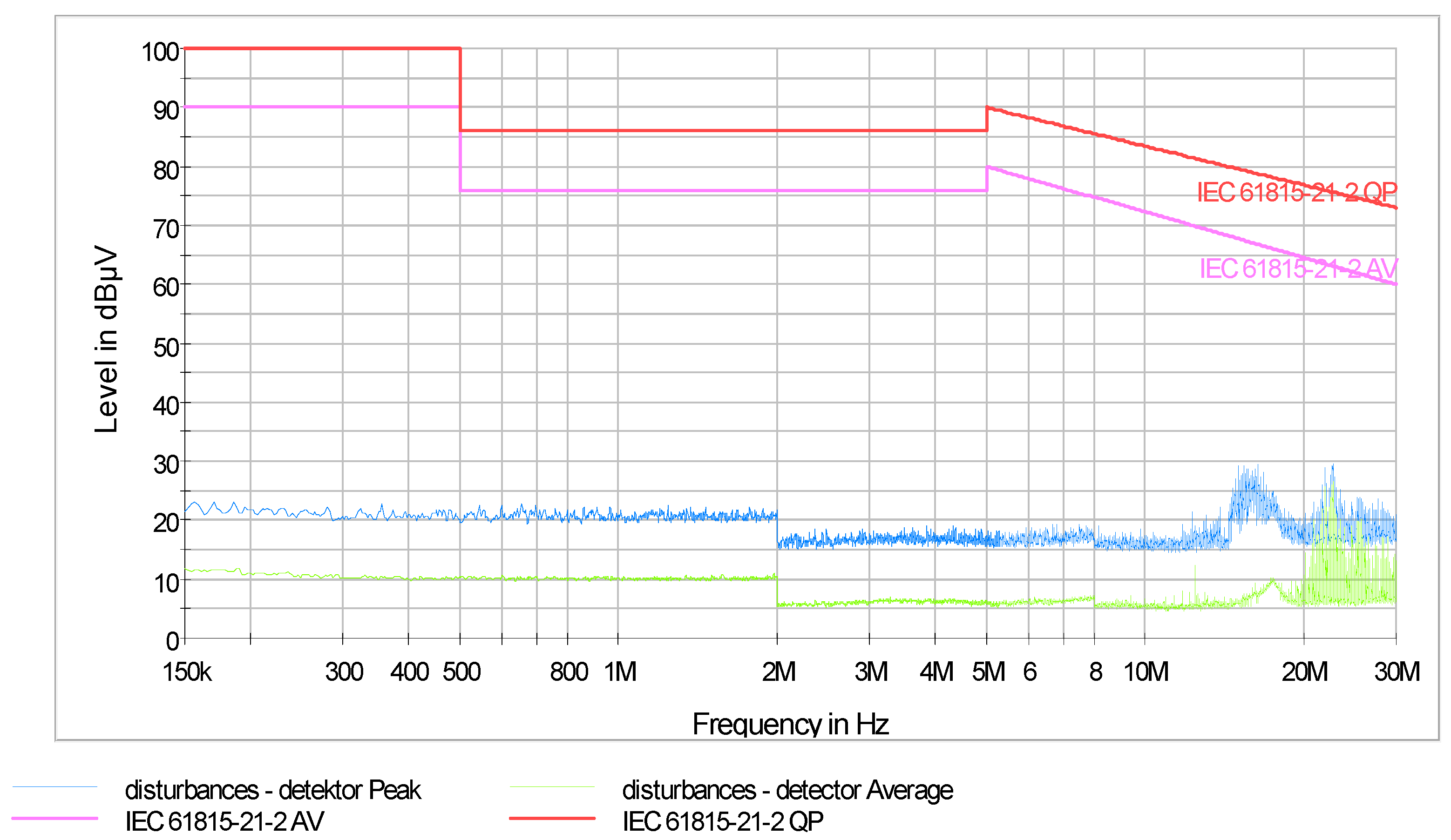
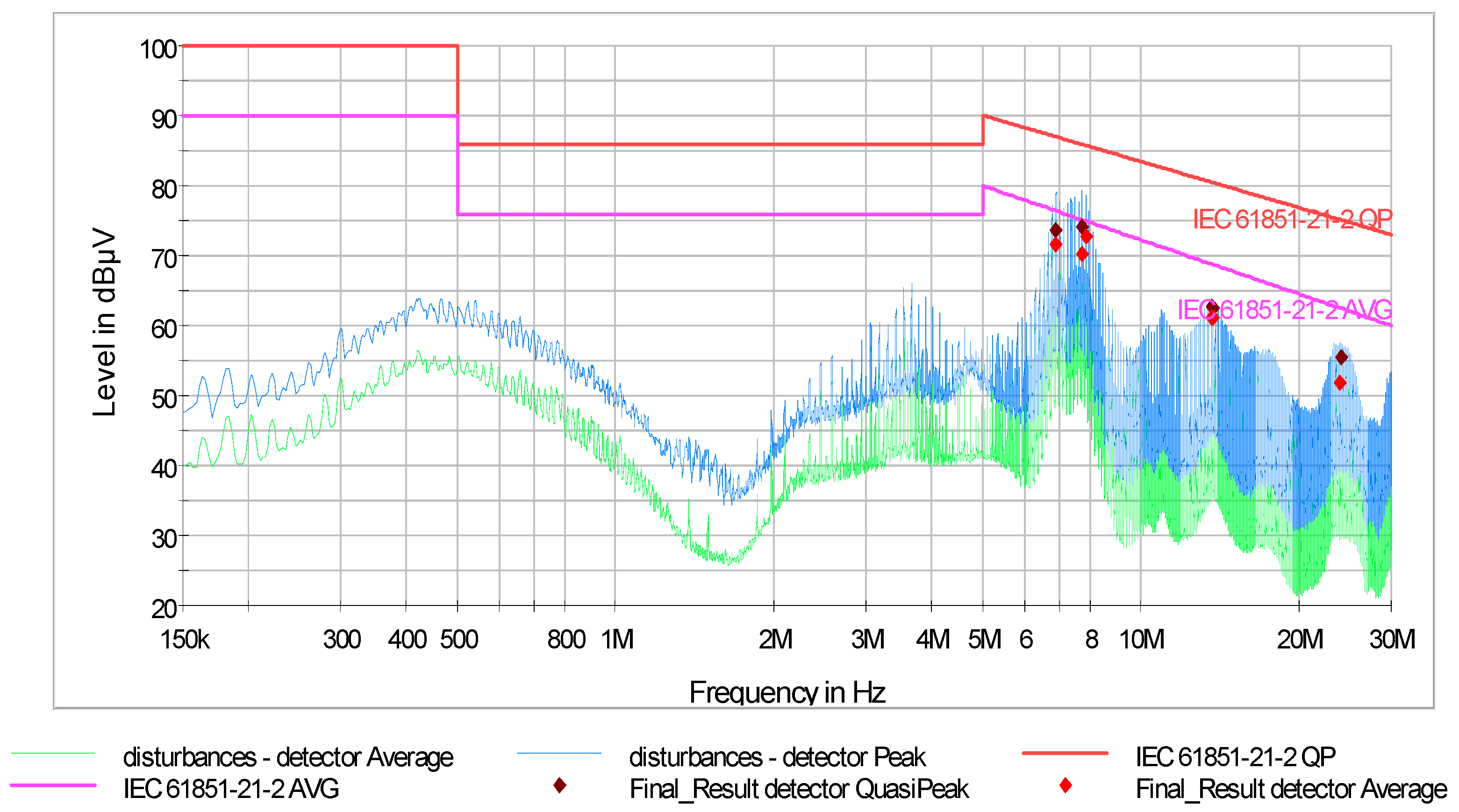
3.2. Conductive Electromagnetic Emissions

Tests of the PLUGinEV charging station were conducted in two stages. The first part of the tests were precompilation engineering tests carried out in the Electromagnetic Compatibility Laboratory of the Lublin University of Technology. A professional interference meter was used for the measurements—EMI test receiver, model ESCI3 Rohde & Schwarz GmbH & Co KG. In the power circuit, a three-phase line impedance stabilization network (model SMZ-6/50, INCO Warszawa) was used. Disturbances in phases L1, L2, and L3 were examined by switching consecutive measurement points in this artificial network. All measurements were made using an average value detector (AV). The first tests showed that the permissible limits were exceeded (Figure 9, red line—IEC 61851-21-2).
Repair work was necessary. Among other things, the installation inside the charger was improved, shielded cables were used, the grounding of many internal devices and modules was improved, and the RFI filter (Schaffner FN3280H-36-33FN model) was selected. Filter selection was possible because the disturbance level characteristics were known. In addition, operating current parameters and geometrical dimensions were also taken into account. After these actions, the final tests were started. These tests were carried out in an accredited Electromagnetic Compatibility Laboratory of the Wrocław University of Technology. The photo from the tests is shown in Figure 2b and the test results are presented in Figure 10, Figure 11 and Figure 12.
In the measurement system, a Rohde & Schwarz 20 Hz–8 GHz ESU EMI Test Receiver and Artificial Mains Network ESH2 Z5 were used. All results were generated in dedicated EMC32 software for emc measurements by Rohde & Schwarz GmbH & Co KG, Munich, Germany. The characteristics in Figure 10, Figure 11 and Figure 12 show the results of measurements of the charging station loaded with a resistance simulator. In the background of each measurement, the permissible limits are visible. In addition, maximum values (hot spots) that were close to the limit of the standard were retested with a quasipeak detector. The measurement with the quasipeak detector was conclusive, according to metrological practice. These points are indicated by colored markings on the graph. No excess emission levels were found while analyzing all states of operation. This means that corrective actions ensured that the electromagnetic compatibility requirements were met.
From the characteristics of the conductive disturbances presented above, it is clearly visible that the disturbance levels during the AC module operation were small, while were higher during the DC module operation. AC operation basically transfers energy directly to the vehicle, and the charging station only monitors the transfer, and ensures safety. When the station is working with a DC module, the energy is transferred from the power system via converter systems to the vehicle. As can be seen, power electronic systems are a source of disturbances, especially in the 6–9 MHz range. The nature of the disturbances depends on the load—at 80% power, a clear increase in the disturbance level was visible. The filter selected was good and had high damping efficiency, which ensures that the compatibility requirements are met. The results presented in [61] of conductive disturbance measurements of three different high-power-charging columns also showed that EMC troubleshooting practices were significant. The initial measurements of conductive disturbances were above the limits, however, after EMC troubleshooting, the conducted disturbances emissions were reduced. The authors of this article presented a similar scenario. The first results (Figure 9) indicated that the conducted disturbances were exceeded. After selecting the appropriate filtering system, positive test results were obtained (Figure 10, Figure 11 and Figure 12).

4. Conclusions

The development of electromobility poses challenges for the electric power and transportation industries. The increased use of electric vehicles will create a large demand for electricity. At the same time, thousands–millions of charging stations will appear in the power system, which will affect the power system as well as power quality. The construction of EV charging devices should take into account not only the economics, convenience of use by consumers, and the profit model of energy supply companies, but also the impact on the power quality parameters on the power system. Charging stations put into use must meet electromagnetic compatibility requirements. Especially important are the aspects of feedback of conducted disturbances and harmonics into the power system. Their high values will cause damage to equipment and power quality. Therefore, it is important to research and test facilities that will increasingly affect the system.
This paper presents the results of research on the analysis of current harmonics and the level of conducted disturbances of the 150 kHz–30 MHz band of charging stations. Presented accurate information about the level of real disturbances is important for people who deal with the management of electric energy flow in the power system and its quality. Valuable information is also provided by the connection of two types of tests: harmonic content and electromagnetic disturbances. Tests of the harmonic distribution of objects operating in the power system have been conducted for a long time [27,65,69,70,71,72,73], but it should be remembered that not only harmonics but also conducted electromagnetic disturbances affect the quality of electricity.
Electric vehicle charging stations are non-linear high power devices that generate current harmonics and high-frequency conductive interference. This is an effect of the technologies based on power electronics. Tests made after designing the device are intended to test the object and in the case of negative results, are the basis for actions improving electromagnetic compatibility. Measurements in an accredited laboratory are proof of achieving the appropriate levels of compatibility.
However, the measured level of conducted disturbance (resulting from the power electronics used in the charging station) replicated in hundreds of units incorporated into the local power system circuit will be noticeable. Determining the strength of these impacts is beyond the scope of this article, but provides a starting point for power quality management analyses.
This was the initial stage of research. Its purpose was to identify the level of harmonics and distortions influencing the power grid. It is a starting point for further analyses—determining harmonic changes and disturbances during charging. The obtained experimental results are significant because they can be used for the authors and other researchers to model the impact of EV chargers on the power grid and the power quality.
It is worth noting that the analysis was based on a single electric vehicle and models from different manufacturers may have different designs for the on-board charger. Therefore, it is important that such studies take into account different EV models and different charging stations in the future. The results presented are intended to help electricity distribution companies understand the possible impact of these new loads on electrical grids in order to prepare them for a possible mass introduction of EV.

Author Contributions

Conceptualization, P.M. and A.C.; Methodology, A.C. and P.M.; Writing—original draft preparation, A.C. and P.M.; Writing—review and editing, A.C. and P.M. All authors have read and agreed to the published version of the manuscript.

Funding

This research received no external funding.

Institutional Review Board Statement

Not applicable.

Informed Consent Statement

Not applicable.

Acknowledgments

This work was supported by Lublin University of Technology, Grant No. FD-20/EE-2/412.

Conflicts of Interest

The authors declare no conflict of interest.

References

  1. Tucki, K.; Orynycz, O.; Świć, A.; Mitoraj-Wojtanek, M. The Development of Electromobility in Poland and EU States as a Tool for Management of CO2 Emissions. Energies 2019, 12, 2942. [Google Scholar] [CrossRef] [Green Version]
  2. Polish Ministry of Energy. Electromobility Development Plan in Poland “Energy for the Future”; Polish Ministry of Energy: Warsaw, Poland, 2017.
  3. Johansson, S.; Persson, J.; Lazarou, S.; Theocharis, A. Investigation of the Impact of Large-Scale Integration of Electric Vehicles for a Swedish Distribution Network. Energies 2019, 12, 4717. [Google Scholar] [CrossRef] [Green Version]
  4. Li, W.; Lin, Z.; Cai, K.; Zhou, H.; Yan, G. Multi-Objective Optimal Charging Control of Plug-In Hybrid Electric Vehicles in Power Distribution Systems. Energies 2019, 12, 2563. [Google Scholar] [CrossRef] [Green Version]
  5. International Energy Agency. Global EV Outlook 2021. Accelerating Ambitions despite the Pandemic; International Energy Agency: Paris, France, 2021. [Google Scholar]
  6. Global EV Data Explorer. Available online: https://www.iea.org/articles/global-ev-data-explorer (accessed on 4 November 2021).
  7. International Energy Agency. Global EV Outlook 2020; International Energy Agency: Paris, France, 2020. [Google Scholar]
  8. Polski Licznik Elektromobilności. Available online: https://pspa.com.pl/ (accessed on 4 November 2021).
  9. The National Fund for Environmental Protection and Water Management Will Co-Finance the Purchase of Electric Vehicles. Available online: https://www.gov.pl/web/climate/the-national-fund-for-environmental-protection-and-water-management-will-co-finance-the-purchase-of-electric-vehicles (accessed on 10 October 2021).
  10. Dotacje Do Aut Elektrycznych Okazały Się Klapą. Available online: https://moto.rp.pl/tu-i-teraz/46109-dotacje-do-aut-elektrycznych-okazaly-sie-klapa (accessed on 15 October 2021).
  11. Kaushal, J.; Basak, P. Power quality control based on voltage sag/swell, unbalancing, frequency, THD and power factor using artificial neural network in PV integrated AC microgrid. Sustain. Energy Grids Netw. 2020, 23, 100365. [Google Scholar] [CrossRef]
  12. Nömm, J.; Rönnberg, S.; Bollen, M. An Analysis of Voltage Quality in a Nanogrid during Islanded Operation. Energies 2019, 12, 614. [Google Scholar] [CrossRef] [Green Version]
  13. Mazurek, P. Chosen Aspects of the Electromagnetic Compatibility of Plasma Reactors with Gliding Arc Discharges. Appl. Sci. 2020, 10, 3789. [Google Scholar] [CrossRef]
  14. Wannous, K.; Toman, P. Evaluation of Harmonics Impact on Digital Relays. Energies 2018, 11, 893. [Google Scholar] [CrossRef] [Green Version]
  15. Al-Saadi, M.; Patkowski, B.; Zaremba, M.; Karwat, A.; Pol, M.; Chełchowski, Ł.; Mierlo, J.V.; Berecibar, M. Slow and Fast Charging Solutions for Li-Ion Batteries of Electric Heavy-Duty Vehicles with Fleet Management Strategies. Sustainability 2021, 13, 639. [Google Scholar] [CrossRef]
  16. Awadallah, M.A.; Singh, B.N.; Venkatesh, B. Impact of EV Charger Load on Distribution Network Capacity: A Case Study in Toronto. Can. J. Electr. Comput. Eng. 2016, 39, 268–273. [Google Scholar] [CrossRef]
  17. Lucas, A.; Trentadue, G.; Scholz, H.; Otura, M. Power Quality Performance of Fast-Charging under Extreme Temperature Conditions. Energies 2018, 11, 2635. [Google Scholar] [CrossRef] [Green Version]
  18. Richardson, P.; Flynn, D.; Keane, A. Impact assessment of varying penetrations of electric vehicles on low voltage distribution systems. In Proceedings of the IEEE PES General Meeting, Minneapolis, MN, USA, 25–29 July 2010; pp. 1–6. [Google Scholar]
  19. Zagrajek, K.; Paska, J.; Kłos, M.; Pawlak, K.; Marchel, P.; Bartecka, M.; Michalski, Ł.; Terlikowski, P. Impact of Electric Bus Charging on Distribution Substation and Local Grid in Warsaw. Energies 2020, 13, 1210. [Google Scholar] [CrossRef] [Green Version]
  20. Wang, J.; Cui, Y.; Zhu, M. Probabilistic Harmonic Calculation in Distribution Networks with Electric Vehicle Charging Stations. J. Appl. Math. 2014, 2014, 167565. [Google Scholar] [CrossRef]
  21. Zhang, Y.; Yu, D.; Zhang, G.; Wang, H.; Zhuang, J. Harmonic Analysis of EV Charging Station Based on Measured Data. In Proceedings of the 2020 IEEE/IAS Industrial and Commercial Power System Asia (I&CPS Asia), Weihai, China, 13–16 July 2020; pp. 475–480. [Google Scholar]
  22. Alame, D.; Azzouz, M.; Kar, N. Assessing and Mitigating Impacts of Electric Vehicle Harmonic Currents on Distribution Systems. Energies 2020, 13, 3257. [Google Scholar] [CrossRef]
  23. Bass, R.; Zimmerman, N. Impacts of Electric Vehicle Charging on Electric Power Distribution Systems; Transportation Research and Education Center (TREC): Portland, OR, USA, 2013. [Google Scholar]
  24. Melo, N.; Mira, F.; de Almeida, A.; Delgado, J. Integration of PEV in Portuguese distribution grid: Analysis of harmonic current emissions in charging points. In Proceedings of the 11th International Conference on Electrical Power Quality and Utilisation, Lisbon, Portugal, 17–19 October 2011; pp. 1–6. [Google Scholar]
  25. Bhajana, V.V.S.K.; Jarzyna, W.; Fatyga, K.; Zielinski, D.; Kwaśny, L. Performance of a SiC MOSFET based isolated dual active bridge dc-dc converter for electro-mobility applications. Rev. Roum. Sci. Tech. Ser. Électrotech. Énergétique 2019, 64, 383–390. [Google Scholar]
  26. van der Burgt, J.; Vera, S.P.; Wille-Haussmann, B.; Andersen, A.N.; Tambjerg, L.H. Grid impact of charging electric vehicles; study cases in Denmark, Germany and The Netherlands. In Proceedings of the 2015 IEEE Eindhoven PowerTech, Eindhoven, The Netherlands, 29 June–2 July 2015; pp. 1–6. [Google Scholar]
  27. Lucas, A.; Bonavitacola, F.; Kotsakis, E.; Fulli, G. Grid harmonic impact of multiple electric vehicle fast charging. Electr. Power Syst. Res. 2015, 127, 13–21. [Google Scholar] [CrossRef]
  28. Batorowicz, D.S.; Zimmer, H.; Franz, P.; Hanson, J. Impact of Battery Charging of Electric Vehicles on Power Quality in Smart Homes and Low-Voltage Distribution Networks. In Proceedings of the International Conference on Renewable Energies and Power Quality, Madrid, Spain, 4–6 May 2016. [Google Scholar]
  29. Un-Noor, F.; Padmanaban, S.; Mihet-Popa, L.; Mollah, M.; Hossain, E. A Comprehensive Study of Key Electric Vehicle (EV) Components, Technologies, Challenges, Impacts, and Future Direction of Development. Energies 2017, 10, 1217. [Google Scholar] [CrossRef] [Green Version]
  30. Dharmakeerthi, C.; Mithulananthan, N.; Saha, T.K. Overview of the impacts of plug-in electric vehicles on the power grid. In Proceedings of the 2011 IEEE PES Innovative Smart Grid Technologies, Perth, Australia, 13–16 November 2011; pp. 1–8. [Google Scholar]
  31. Wang, L.; Qin, Z.; Slangen, T.; Bauer, P.; van Wijk, T. Grid Impact of Electric Vehicle Fast Charging Stations: Trends, Standards, Issues and Mitigation Measures—An Overview. IEEE Open J. Power Electron. 2021, 2, 56–74. [Google Scholar] [CrossRef]
  32. Pieltain Fernandez, L.; Gomez San Roman, T.; Cossent, R.; Mateo Domingo, C.; Frias, P. Assessment of the Impact of Plug-in Electric Vehicles on Distribution Networks. IEEE Trans. Power Syst. 2011, 26, 206–213. [Google Scholar] [CrossRef]
  33. Pillai, J.R.; Bak-Jensen, B. Impacts of electric vehicle loads on power distribution systems. In Proceedings of the 2010 IEEE Vehicle Power and Propulsion Conference, Lille, France, 1–3 September 2010; pp. 1–6. [Google Scholar]
  34. Masoum, M.A.; Moses, P.S.; Smedley, K.M. Distribution transformer losses and performance in smart grids with residential plug-in electric vehicles. In Proceedings of the ISGT 2011, Anaheim, CA, USA, 17–19 January 2011; pp. 1–7. [Google Scholar]
  35. Deilami, S.; Masoum, A.S.; Moses, P.S.; Masoum, M.A.S. Voltage profile and THD distortion of residential network with high penetration of Plug-in Electrical Vehicles. In Proceedings of the 2010 IEEE PES Innovative Smart Grid Technologies Conference Europe (ISGT Europe), Gothenburg, Sweden, 11–13 October 2010; pp. 1–6. [Google Scholar]
  36. Slangen, T.; van Wijk, T.; Ćuk, V.; Cobben, S. The Propagation and Interaction of Supraharmonics from Electric Vehicle Chargers in a Low-Voltage Grid. Energies 2020, 13, 3865. [Google Scholar] [CrossRef]
  37. Chudy, A.; Stryczewska, H.D. Electromagnetic Compatibility Testing of Electric Vehicles and Their Chargers. Inform. Autom. Pomiary Gospod. Ochr. Sr. 2020, 10, 70–73. [Google Scholar] [CrossRef]
  38. Chudy, A.; Mazurek, P. Electromobility—The Importance of Power Quality and Environmental Sustainability. J. Ecol. Eng. 2019, 20, 15–23. [Google Scholar] [CrossRef]
  39. Baraniak, J.; Starzyński, J. Modeling the Impact of Electric Vehicle Charging Systems on Electric Power Quality. Energies 2020, 13, 3951. [Google Scholar] [CrossRef]
  40. Liang, Z.; Chen, H.; Wang, X.; Chen, S.; Zhang, C. Risk-Based Uncertainty Set Optimization Method for Energy Management of Hybrid AC/DC Microgrids With Uncertain Renewable Generation. IEEE Trans. Smart Grid 2020, 11, 1526–1542. [Google Scholar] [CrossRef]
  41. Watson, N.; Watson, R.; Paterson, T.; Russell, G.; Ellerington, M.; Langella, R. Power Quality of a bidirectional Electric Vehicle charger. In Proceedings of the 2020 19th International Conference on Harmonics and Quality of Power (ICHQP), Dubai, United Arab Emirates, 6–7 July 2020; pp. 1–5. [Google Scholar]
  42. Das, H.S.; Rahman, M.M.; Li, S.; Tan, C.W. Electric vehicles standards, charging infrastructure, and impact on grid integration: A technological review. Renew. Sustain. Energy Rev. 2020, 120, 109618. [Google Scholar] [CrossRef]
  43. Iqbal, M.N.; Kütt, L.; Asad, B.; Vaimann, T.; Rassõlkin, A.; Demidova, G.L. Time Dependency of Current Harmonics for Switch-Mode Power Supplies. Appl. Sci. 2020, 10, 7806. [Google Scholar] [CrossRef]
  44. Fatyga, K.; Zieliński, D. Comparison of main control strategies for DC/DC stage of bidirectional vehicle charger. In Proceedings of the 2017 International Symposium on Electrical Machines (SME), Naleczow, Poland, 18–21 June 2017; pp. 1–4. [Google Scholar]
  45. Zieliński, D.; Fatyga, K. Dual Active Bridge as a DC Link Current Pulsation Compensator in Energy Storage Applications. Energies 2021, 14, 6141. [Google Scholar] [CrossRef]
  46. Jarzyna, W.; Zieliński, D.; Gopakumar, K. An evaluation of the accuracy of inverter sync angle during the grid’s disturbances. Metrol. Meas. Syst. 2020, 27, 355–371. [Google Scholar]
  47. Shen, Y.; Abubakar, M.; Liu, H.; Hussain, F. Power Quality Disturbance Monitoring and Classification Based on Improved PCA and Convolution Neural Network for Wind-Grid Distribution Systems. Energies 2019, 12, 1280. [Google Scholar] [CrossRef] [Green Version]
  48. Castello, P.; Muscas, C.; Pegoraro, P.; Sulis, S. PMU’s Behavior with Flicker-Generating Voltage Fluctuations: An Experimental Analysis. Energies 2019, 12, 3355. [Google Scholar] [CrossRef] [Green Version]
  49. Tariq, M.; Adnan, M. Stabilizing super smart grids using v2g: A probabilistic analysis. In Proceedings of the 2019 IEEE 89th Vehicular Technology Conference (VTC2019-Spring), Kuala Lumpur, Malaysia, 28 April–1 May 2019; pp. 1–5. [Google Scholar]
  50. Deb, S.; Tammi, K.; Kalita, K.; Mahanta, P. Impact of Electric Vehicle Charging Station Load on Distribution Network. Energies 2018, 11, 178. [Google Scholar] [CrossRef] [Green Version]
  51. Ding, T.; Chen, H.; Wu, B.; Hu, P. Harmonic characteristics analysis of PWM-based electric vehicle chargers considering control strategy. In Proceedings of the 2018 18th International Conference on Harmonics and Quality of Power (ICHQP), Ljubljana, Slovenia, 13–16 May 2018; pp. 1–5. [Google Scholar]
  52. Arranz-Gimon, A.; Zorita-Lamadrid, A.; Morinigo-Sotelo, D.; Duque-Perez, O. A Review of Total Harmonic Distortion Factors for the Measurement of Harmonic and Interharmonic Pollution in Modern Power Systems. Energies 2021, 14, 6467. [Google Scholar] [CrossRef]
  53. Michalec, Ł.; Jasiński, M.; Sikorski, T.; Leonowicz, Z.; Jasiński, Ł.; Suresh, V. Impact of Harmonic Currents of Nonlinear Loads on Power Quality of a Low Voltage Network–Review and Case Study. Energies 2021, 14, 3665. [Google Scholar] [CrossRef]
  54. Zheng, Y.; Niu, S.; Shang, Y.; Shao, Z.; Jian, L. Integrating plug-in electric vehicles into power grids: A comprehensive review on power interaction mode, scheduling methodology and mathematical foundation. Renew. Sustain. Energy Rev. 2019, 112, 424–439. [Google Scholar] [CrossRef]
  55. Christidis, P.; Focas, C. Factors Affecting the Uptake of Hybrid and Electric Vehicles in the European Union. Energies 2019, 12, 3414. [Google Scholar] [CrossRef] [Green Version]
  56. International Electrotechnical Commission. Electromagnetic Compatibility (EMC)—Part 3-12: Limits—Limits for Harmonic Currents Produced by Equipment Connected to Public Low-Voltage Systems with Input Current >16 A and ≤75 A per Phase, 2nd ed.; IEC 61000-3-12; International Electrotechnical Commission: Geneva, Switzerland, 2011. [Google Scholar]
  57. Li, Z.; Shao, T.; Zheng, T.Q.; Li, H.; Huang, B. Interference source analysis and EMC design for All-SiC power module in EV charger. Microelectron. Reliab. 2019, 100–101, 113458. [Google Scholar] [CrossRef]
  58. Sandrolini, L.; Thomas, D.W.; Sumner, M.; Rose, C. Measurement and evaluation of the conducted emissions of a DC/DC power converter in the frequency range 2–150 kHz. In Proceedings of the 2018 IEEE Symposium on Electromagnetic Compatibility, Signal Integrity and Power Integrity (EMC, SI & PI), Long Beach, CA, USA, 30 July–3 August 2018; pp. 345–350. [Google Scholar]
  59. Pliakostathis, K.; Scholz, H. On the Evaluation of Electromagnetic Compatibility (EMC) of a Prototype Electric Vehicle; Publications Office of the European Union: Luxembourg, 2018. [Google Scholar]
  60. Pliakostathis, K.; Zanni, M.; Trentadue, G.; Scholz, H.; Kluge, D.H.; Frankholz, M.; Sauer, L.; Becker, E.; Weckermann, C.; Demirci, G.; et al. Electromagnetic Compatibility (EMC) Evaluation of a Prototype Solar-Charged Electric Race-Car; Publications Office of the European Union: Luxembourg, 2019. [Google Scholar]
  61. Pliakostathis, K.; Zanni, M.; Scholz, H.; Trentadue, G. Assessment and Analysis of the Electromagnetic Profile of Prototype High-Power-Charging Units for Electric Vehicles; Publications Office of the European Union: Luxembourg, 2019. [Google Scholar]
  62. Politechnika Lubelska; PGE Dystrybucja. PLUGinEV—Electric Vehicle Charging System Integrated with Lighting Infrastructure, EU Project POIR.04.01.02-00-0052/16. Available online: http://pluginev.pollub.pl (accessed on 27 October 2021).
  63. International Electrotechnical Commission. Electromagnetic Compatibility (EMC)—Part 3-2: Limits—Limits for Harmonic Current Emissions (Equipment Input Current ≤16 A per Phase), 4th ed.; IEC 61000-3-2; International Electrotechnical Commission: Geneva, Switzerland, 2014. [Google Scholar]
  64. International Electrotechnical Commission. Electric Vehicle Conductive Charging System—Part 21-2: Electric Vehicle Requirements for Conductive Connection to an AC/DC Supply—EMC Requirements for off Board Electric Vehicle Charging Systems; IEC 61851-21-2; International Electrotechnical Commission: Geneva, Switzerland, 2018. [Google Scholar]
  65. Foskolos, G. Measurement-Based Current-Harmonics Modeling of Aggregated Electric-Vehicle Loads Using Power-Exponential Functions. World Electr. Veh. J. 2020, 11, 51. [Google Scholar] [CrossRef]
  66. Slangen, T.; van Wijk, T.; Ćuk, V.; Cobben, J. The harmonic and supraharmonic emission of battery electric vehicles in the Netherlands. In Proceedings of the 2020 International Conference on Smart Energy Systems and Technologies (SEST), Istanbul, Turkey, 7–9 September 2020; pp. 1–6. [Google Scholar]
  67. Wu, G.; Xu, B.; Yu, H.; Dong, E. Power quality analysis and harmonic suppression of high latitude and high alpine region electric vehicles charging station. In Proceedings of the 2013 World Electric Vehicle Symposium and Exhibition (EVS27), Barcelona, Spain, 17–20 November 2013; pp. 1–5. [Google Scholar]
  68. Sabarimuthu, M.; Senthilnathan, N.; Monnisha, A.; KamaleshKumar, V.; Sree, S.K.; Sundari, P.M. Measurement and Analysis of Power Quality Issues Due to Electric Vehicle Charger. In Proceedings of the IOP Conference Series: Materials Science and Engineering, Sanya, China, 12–14 November 2021; p. 012131. [Google Scholar]
  69. Rahman, S.; Shrestha, G.B. An investigation into the impact of electric vehicle load on the electric utility distribution system. IEEE Trans. Power Deliv. 1993, 8, 591–597. [Google Scholar] [CrossRef]
  70. Wanik, M.; Siam, M.F.; Ayob, A.; Mohamed, A.; HanifahAzit, A.; Sulaiman, S.; Ali, M.A.M.; Hussein, Z.F.; MatHussin, A.K. Harmonic Measurement and Analysis during Electric Vehicle Charging. Engineering 2013, 5, 215–220. [Google Scholar] [CrossRef]
  71. Taylor, J.; Maitra, A.; Alexander, M.; Brooks, D.; Duvall, M. Evaluations of plug-in electric vehicle distribution system impacts. In Proceedings of the IEEE PES General Meeting, Minneapolis, MN, USA, 25–29 July 2010; pp. 1–6. [Google Scholar]
  72. Kim, K.; Song, C.S.; Byeon, G.; Jung, H.; Kim, H.; Jang, G. Power demand and total harmonic distortion analysis for an EV charging station concept utilizing a battery energy storage system. J. Electr. Eng. Technol. 2013, 8, 1234–1242. [Google Scholar] [CrossRef] [Green Version]
  73. Ćuk, V.; Cobben, J.F.; Kling, W.L.; Ribeiro, P.F. Analysis of harmonic current summation based on field measurements. IET Gener. Transm. Distrib. 2013, 7, 1391–1400. [Google Scholar] [CrossRef]
Figure 1. Impacts of EVs on power quality.
Energies 15 00244 g001
Figure 2. The PLUGinEV charging station. (a) BMW i3 connected to the tested charging station at the laboratory of the Lublin University of Technology; (b) the PLUGinEV charging station during electromagnetic emission measurements in the screen chamber at the Wrocław University of Technology.
Energies 15 00244 g002
Figure 3. The laboratory setup for harmonic current emission measurements.
Energies 15 00244 g003
Figure 4. Test setup for the measurement of the harmonic current emission of the EV charging station.
Energies 15 00244 g004
Figure 5. Diagram of the measurement system for testing conductive disturbances (EUT—equipment under test, AMN—Artificial Mains Network).
Energies 15 00244 g005
Figure 6. The harmonic current emissions when charging a BMW i3 compared with the limits of the IEC 61000-3-2 standard and IEC 61000-3-12 standard.
Energies 15 00244 g006
Figure 7. The harmonic current spectrum of an AC module (80% of power).
Energies 15 00244 g007
Figure 8. The harmonic current spectrum of a DC module (80% of power).
Energies 15 00244 g008
Figure 9. Conductive disturbance of the charging station, DC module operation (80% of power).
Energies 15 00244 g009
Figure 10. Conductive disturbances of the charging station, AC module operation (80% power), IEC 61851-21-2 limits for average (AV) and quasipeak detectors (QP); blue line—disturbance level measured by the peak detector, green line—disturbance level measured by the average detector.
Energies 15 00244 g010
Figure 11. Conductive disturbances of the charging station, DC module operation (20% power), IEC 61851-21-2 limits for average and quasipeak detectors; blue line—disturbance level measured by the peak detector, green line—disturbance level measured by the averaging detector.
Energies 15 00244 g011
Figure 12. Conductive disturbance of the charging station, DC module operation (80% power), IEC 61851-21-2 limits for average and quasipeak detectors; blue line—disturbance level measured by the peak detector, green line—disturbance level measured by the averaging detector.
Energies 15 00244 g012
Table 1. THDI values during BMW i3 charging and during the tests of the AC and DC modules.
PhaseTHDI during BMW i3 ChargingTHDI of the AC ModuleTHDI of the DC Module
L13.37%0.29%4.43%
L2- 10.17%4.13%
L3- 11.98%4.61%
1 BMW i3 car charging was performed in single-phase mode, THDI analysis in L2 and L3 phases omitted.
Publisher’s Note: MDPI stays neutral with regard to jurisdictional claims in published maps and institutional affiliations.

