Article

Innovative Construction of the AFPM-Type Electric Machine and the Method for Estimation of Its Performance Parameters on the Basis of the Induction Voltage Shape

by
Andrzej Smoleń
*,†,
Lesław Gołębiowski
and
Marek Gołębiowski
Department of Electrical and Computer Engineering, Rzeszow University of Technology, 35-959 Rzeszow, Poland
*
Author to whom correspondence should be addressed.
These authors contributed equally to this work.
Energies 2022, 15(1), 236; https://doi.org/10.3390/en15010236
Submission received: 16 November 2021 / Revised: 19 December 2021 / Accepted: 22 December 2021 / Published: 30 December 2021

Abstract

:
The article presents an innovative construction of the Axial Flux Permanent Magnet (AFPM) machine designed for generator performance, which provides the shape of induced voltage that enables estimation of the speed and rotational angle of the machine rotor. Design solutions were proposed, the aim of which is to limit energy losses as a result of the occurrence of eddy currents. The method of direct estimation of the value of the rotational speed and rotational angle of the machine rotor was proposed and investigated on the basis of the measurements of induced voltages and machine phase currents. The advantage of the machine is the utilization of simple and easy-to-use computational procedures. The acquired results were compared with the results obtained for estimation performed by using the Unscented Kalman Filter (UKF).

1. Introduction

One may observe an increasing interest in the application of electric machines of the axial flow of magnetic field in many industrial applications as an alternative to machines of conventional construction. The reason for this situation is that the geometric features of these devices (very big ratio of machine diameter to its axial length) predisposes this type of constructions for such applications as integrated alternators with a combustion engine [1], drive systems of electric vehicles [2,3,4,5], or generators functioning in systems with wind turbines [6,7,8] in particular with the vertical axis of rotation [9,10]. With regard to such a wide range of various applications, there have been many variants of machine constructions with axial flow permanent magnets (AFPM) [11,12,13,14,15,16].
Nowadays, there are numerous variants of AFPM machine constructions. In general, these constructions may be divided into two groups: Core Less AFPMs and machines with a magnetic core.
The solutions in the first group are characterized by a lack of the tapping moment. In the case of a machine designed for operation with a wind turbine, it is of great importance, as it enables the system to begin work with a lower wind speed [17]. The machines of this type can potentially also achieve higher efficiency than magnetic core constructions due to the lack of the occurance of eddy current losses in the core [18]. The main drawback of this solution is small power density and electromagnetic torque achieved by these machines [19]. This results in significant growth of their geometric dimensions (in particular, machine diameter). The classical approach to solving this problem is based on propositions of constructions with a higher number of rotors or stators. Such an approach usually leads to increasing the number/volume of permanent magnets in the machine, which contributes to increased production costs. Machines with a full magnetic core are not a good alternative for C-L AFPM-type constructions in the case of cooperation with wind turbines due to the significant values of the tapping torque [20,21,22]. In the aforementioned applications, what is also very important is providing the possibility of applying the methods of sensorless control of the AFPM machine. In installations of small power, the possibility to resign from sensors allows for a visible reduction of production costs, and it also makes the installation more reliable [23]. Several interesting approaches for addressing this problem have been reported in the literature. In [24], an adaptive quasi-sliding-mode position observer (AQSMO) was presented for a magnet synchronous machine (PMSM) with a salient-pole. The results were used to control this machine at medium and high speeds. An important advantage of adaptive QSMO is its robustness to load changes and fast convergence of the trajectories of the system state variables to the boundary layer designed around the sliding surface. The paper [25] presents an approach for estimating a speed and position of a PMSM rotor with the use of reactive power calculated based on measurements of stator winding voltages and current. This enables the elimination of a differentiation process, which is important due to avoiding a numerical noise effect. The approach presented in [26] deals with the sensorless determination of the angle of rotation and studies the control of the PMSM machine using a phase-locked loop (PLL). The presented methods enable a discrete form of control with a low number of signal samples per voltage period to be used. The presented method shows good robustness to motor parameter uncertainty and electrical measurement errors; however, its usability is restricted to high-speed operation conditions. In paper [27], a novel technique for estimating stator resistance, rotor speed, and position in a vector-controlled drive was developed for all types of PMSM machines. In addition, the method can be used for the estimation and online monitoring of the machine stator winding temperature. The paper [28] considers the estimation of rotor speed and position for a magnetically suspended permanent magnetic synchronous motor (PMSM), which is based on a modified sliding mode observer (SMO). It uses an estimated back EMF and a hyperbolic tangent function. The method has been validated for magnetic flywheel storage systems. A similar problem was considered in [29]. In this case, the theory of the adaptive super twisting sliding mode observer was used to determine the position and speed of the PMSM rotor.
The following article proposes an innovative construction of the AFPM-type machines. The design efforts were focused on providing the generator output voltage shape that would enable estimation on the basis of machine performance parameters (i.e., rotor position and speed) for the purposes of control. The further aim of design works was providing a limitation of the occurrence of losses from eddy currents so as to improve machine efficiency. In the first part of the following article, the construction is presented, and selected results of field analyses performed with the Finite Element Method are discussed. The second part proposes the method of machine operation parameter estimation on the basis of the waveform of the generated voltage. The innovative method presented in this article is based on the first and third harmonic of the voltage on the motor phases. The third harmonic is produced by using a suitable machine design for the purpose of estimation, but it does not occur at the external terminals of the machine because it forms a zero-voltage system. For the purposes of qualitative analysis, the obtained estimation results were compared with those that were obtained by using Kalman filter. The undertaken efforts aim at providing the possibility to control generator operation without the necessity to measure the rotational speed and rotor position angle. The estimation issues of these parameters and the possibility of their utilization in control are discussed in the works of [30,31,32].

2. Proposed Machine Construction

The machine of the proposed construction has a structure enclosed with two rotor sheets on which there are permanent magnets. They form machine poles in the alternating system in such a way that the path of magnetic field flux within one pole pitch encompasses four permanent magnets. The machine stator is located in the central part between rotor sheets, and it is constructed so as to comprise, together with the rotor, within one pole pitch, an integral channel for magnetic field flow. The presence of the channel, whose method of manufacturing and function are described hereafter, is a key part of the described construction. The machine rotor may be constructed in such a way that on the perimeter of its every sheet (in the part that corresponds to the location and length of some of the active coils of stator phase winding), there is a channel whose surface is covered with a layer of low magnetic permeability. The filling of the channel comprises a material that exhibits magnetic anisotropy, which is oriented in such a way that the field flux path would encompass, to the greatest degree, the direction in which the material provides the best values of magnetic permeability. The channel made this way is supposed to provide a path for the flow of magnetic stream. The reduction of flux leakage outside the channel area, by using a coating of low magnetic permeability, is of great importance, in particular in the case of higher ripples of the magnetic field, as it limits eddy current losses that would take place in the material of rotor sheets [33]. It is of great importance, as the power of these losses conveyed in the form of heat would additionally heat the permanent magnets [34], which adversely affects their lifetime. The drawing Figure 1 presents, in a schematic way, the structure of the rotor disc with the elements of a magnetic channel.
The machine stator may be constructed in such a way that the element connecting and retaining in proper locations a particular part is the disc made of a material of low magnetic permeability (epoxy resin type). Alternatively, the disc may also contain a fixture that provides additional stiffness, which is also made of a material of low magnetic permeability and comprising its constituent part. Stator phase windings are located in such a way that coils of consecutive phases are interlaced with each other, comprising a pattern on the perimeter of the stator disc, whose fully symmetric segment is located within one pole pitch. Additionally, in the stator disc, there are also embedded elements made of a material of high magnetic permeability, which is characterized by magnetic anisotropy. It is laid down in such a way that the magnetic field path (enclosed within one pole pitch) goes in the direction in which the material provides the best conditions for magnetic field flow. These elements may be located so as to fill the empty spaces surrounded by particular stator phase winding coils. The machine may be constructed in such a way that with particular rotor positions, the elements of stator of high magnetic permeability (called hereafter stator cores) would form, together with relevant magnetic poles and the magnetic channel, a closed path of magnetic field flow, symmetrically in relation to particular stator winding phases. The drawing Figure 2 presents, in a schematic way, the element that serves the role of a core.
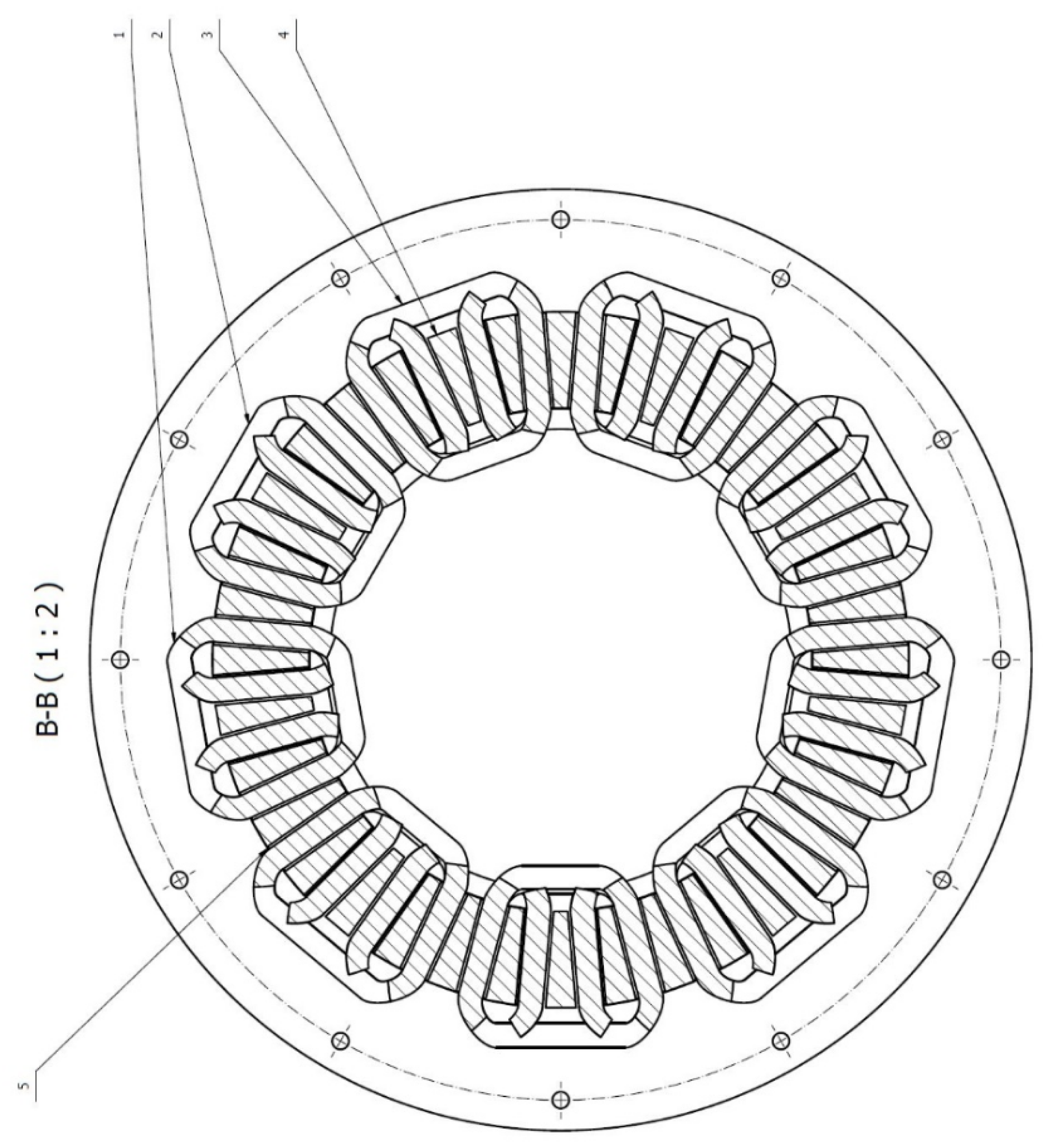
According to the adopted assumption, the shape of voltage generated by the designed machine is supposed to estimate the parameters of its operation for the purposes of sensorless control. For this purpose, a series of simulations studies was made by the use of MES 3D, and the position of phase winding coils and elements comprising the stator core on the machine perimeter that provides a significant value of the third harmonic component in the generated voltage, with a possibly low value of the THD coefficient value of this voltage, was determined. The acquired location of elements is presented in the Figure 3.
The construction parameters of the investigated generator that are crucial from the perspective of field magnetostatic computations are presented in Table 1.

3. Selected Results of Magnetostatic MES3D Calculations

The investigated machine in the variant described herein includes s i x symmetric pole pitches. Due to the fact that phase winding coils interlace each other in the front part, which is shown in Figure 3, in order to correctly reflect in computations the phenomena that take place in this area, it is necessary to make analyses for the model that includes t w o pole pitches. Figure 4 presents the adopted model together with the comparison of finite element meshes generated for the magnetic field error comprising, respectively 1 % and 0.1 % .
Further computations were done for the mesh providing 1 % energy error. Figure 5 presents a vector drawing of flux induction on the plain of cross-sectional area in the axial direction, leading through the center of the front part of one of the coils.
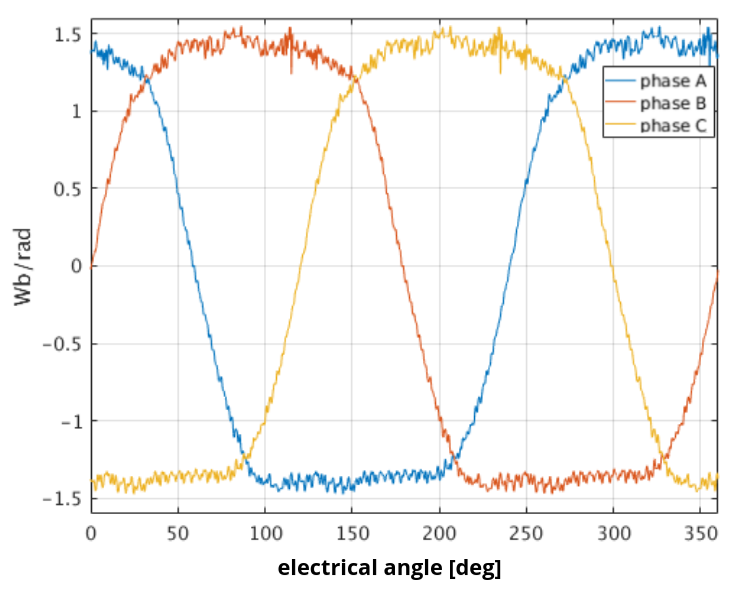
Figure 6 presents waveforms of the magnetic flux derivative from permanent magnets in the angle of rotation. The slight noise that is visible in the presented waveforms is the result of differentiation of the numerical model’s discretion influence.
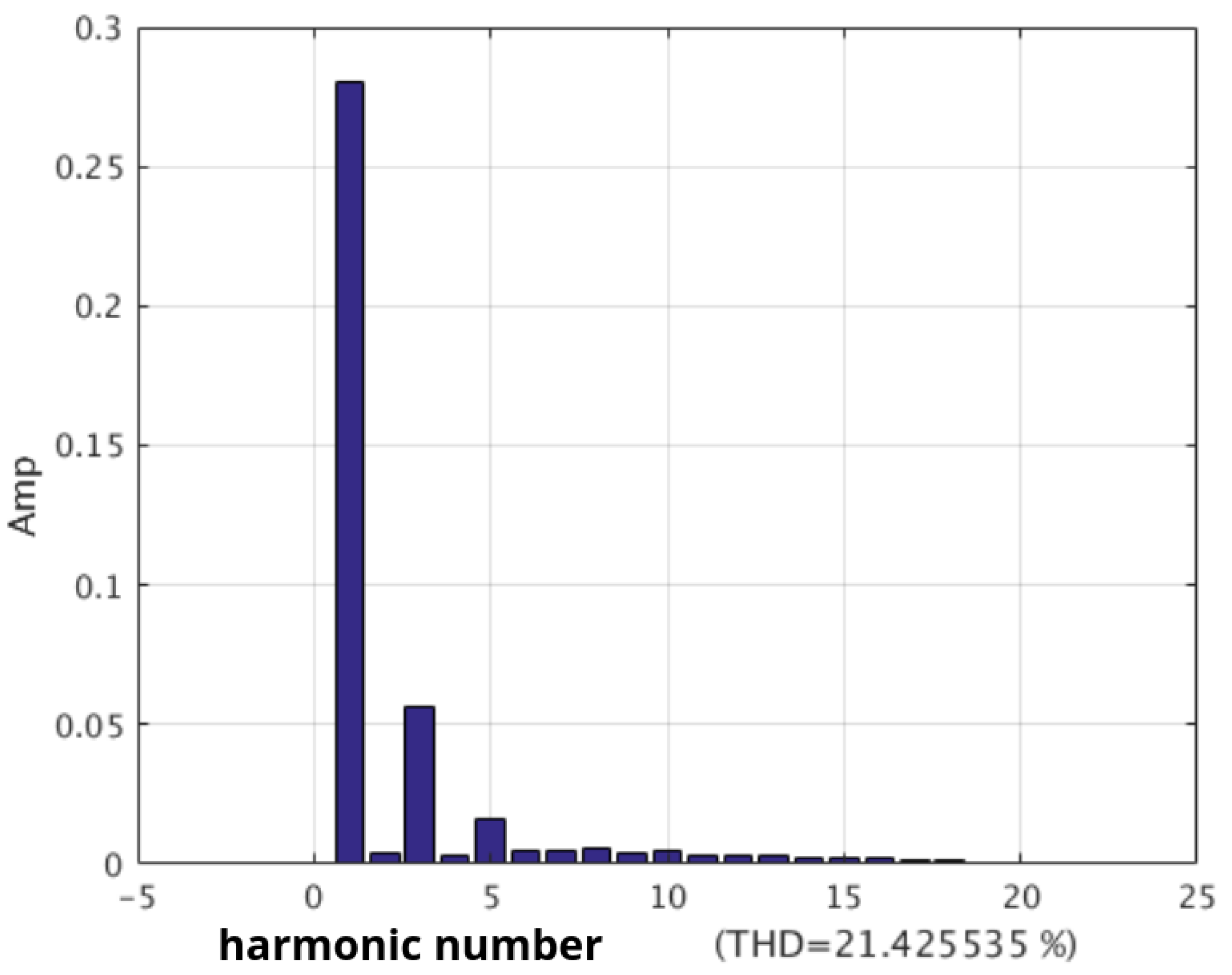
Figure 7 presents computation results of the content of higher harmonic components in the waveform of magnetic flux derivative from permanent magnets in the angle of rotor rotation. A significant share of higher harmonic constituents was obtained. In the later part of the following article, the method of utilizing the obtained machine output voltage waveform shape will be presented in the process of estimation of its performance parameters.
The large THD from the derivative waveform from the magnetic flux in Figure 7 applies to the generator phase voltage. This is intentionally caused by the insertion of the material of high magnetic permeability shown in Figure 2. The purpose is to allow a more accurate estimation of the machine speed. This high THD is caused by the third harmonic of the magnetic flux. Therefore, it is not noticeable in the inter-phase voltage, which is visible outside the generator. There is no risk of exceeding the voltage quality indicators, as stated in the standards.

4. Validation of Results by Comparing with the Obtained Ones, Using Different Approaches

4.1. Determining Magnetic Field Distribution in the Proposed AFPM Machine with the Semi-Analytical Approach

In order to conduct a comparative study, as well as for validation purposes, the magneto static calculations have been repeated using a simplified, hybrid analytical–numerical method. In order to determine induction coefficients, the stator coils are represented by an infinitesimally thin layer for which current flow is defined by using the Fourier series decomposition in such a way so as to reflect the location of coils in a particular phase. In the next step, the Laplace equations are solved for each harmonic in a set considered in an approximated Fourier decomposition, separately in regions 1 and 2. The schematic view of the analytical model is presented in Figure 8.
The following simplifying assumptions were made:
  • Assume an infinitely big value of magnetic permeability for rotor plaids;
  • Assume that the length at X dimension tends to infinity;
  • Curvature was neglected in the model.
The boundary condition in force at the zone boundary, which is a layer with the current, corresponds to the step change in value of the tangent components of the magnetic field intensity vector. This is equal to the current density defined for the k-th of the considered harmonics as a function of X dimension. This can be written down as (1)
y = Y 1 Δ H x n = H x 2 n H x 1 n = K n
where
  • Y 1 denotes the location (on y dimension) of a boundary between two subdomains;
  • Δ H x n represents the difference of magnitudes of the tangent component of the H field vector on both sites of the boundary.
where in accordance with the Fourier decomposition, the current density is given by (2)
K n ( x ) = K ^ n s i n ( u n x ) .
For the remaining part of the boundary that covers the inner site of the rotor discs, the zero value for a tangent component of magnetic field vector H y was adopted as a consequence of assuming that in rotor discs, the magnetic permeability μ . Under these conditions, the Laplace equations are solved analytically for each of the considered current harmonics separately. The final magnetic field distribution is defined as a sum of these intermediate solutions.
The aforementioned method is based on the approach presented in [35], its adaptation for CL-AFPM was shown and is presented in detail in [36]. To perform calculations for the proposed construction of AFPM, further modification of the computational process was needed to enable considering the presence of stator core elements Figure 2. The results obtained using this simplified approach are presented in Table 1.

4.2. Determining the Parameters of the Proposed Construction Using a Simplified 2D FEM Approach

In order to assess if the proposed construction provides a possibility of estimating the rotational speed and angle based on the induced voltage waveform, it is necessary to properly determine the shape of the magnetic flux between phase coils and permanent magnets as a function of rotation angle. This task is considered essential when it comes to computational support of the electrical machines design process. In order to provide the possibility of doing so without the usage of expensive commercial software such as Ansys/Maxwell, an original computer program was developed from scratch.
The elaborated code implements a simplified 2D FEM algorithm. When the goal is to determine the shape of the voltage waveform being induced by the designed generator, the permanent magnets are considered to be the only sources of magnetic field inside the analyzed area. The computational problem comes down to solving the Poisson equation under boundary conditions arising from machine geometry and the physical properties of the materials. Assuming that we analyze the symmetrical section of a magnetic circuit (which is always the case) and taking into account that the magnetic permeability of iron made rotor discs is about 4000 times greater than the magnetic permeability of air, one can conclude that there is no leakage of magnetic field outside the analyzed model. This conclusion is essential for the final mathematical formulation (3) of a problem being solved using an FEM algorithm. A detailed description of mathematical methods, undertaken assumptions, and boundary conditions can be found in [37].
V r o t ( σ A ) 1 μ r o t ( A ) d V = V { σ A I e l + T m a g r o t ( σ A ) } d V
where
  • A is a vector potential;
  • T m a g is a magnetic remanence vector;
  • I e l is the phase winding current.
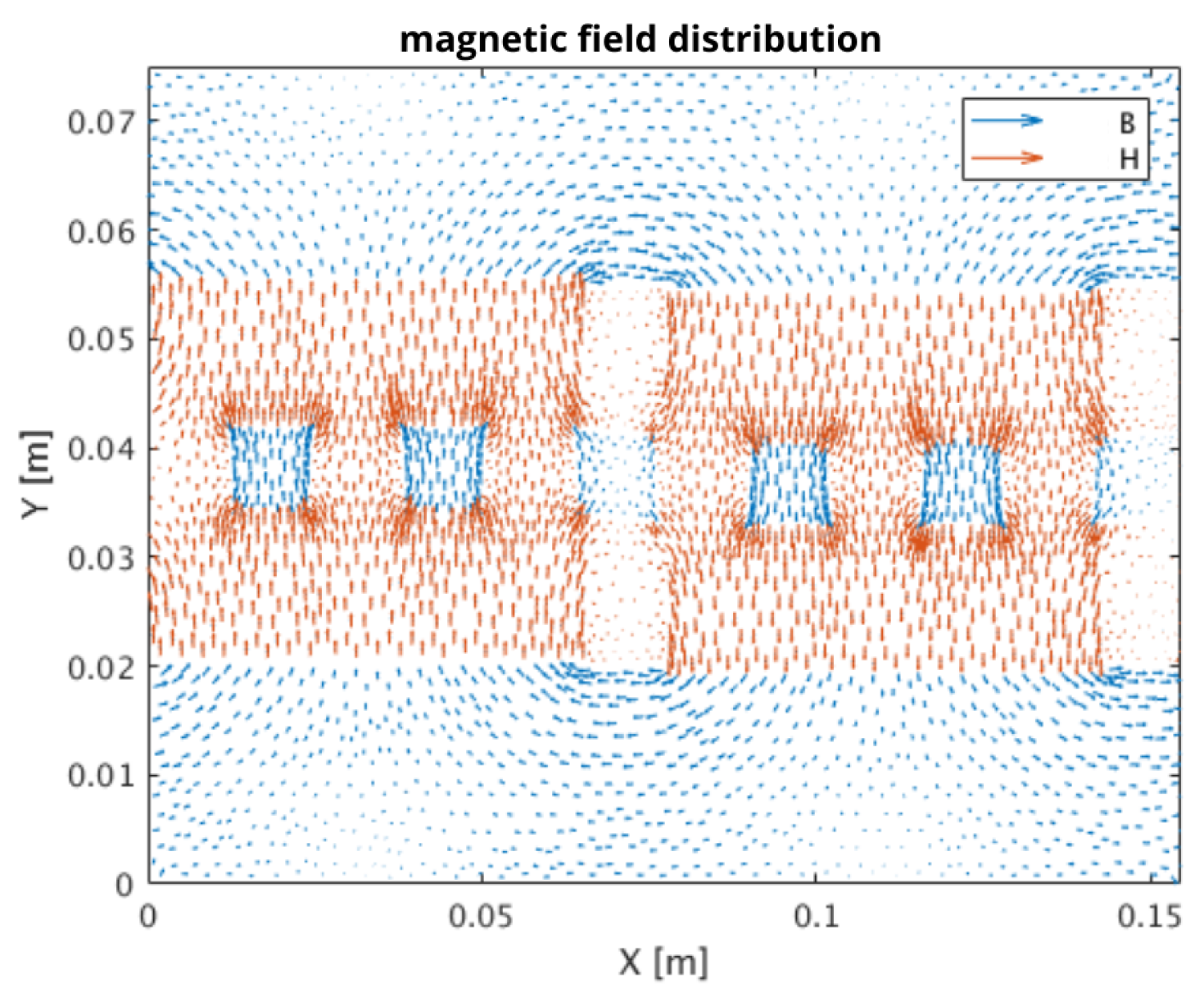
The magnetic field distribution obtained for a single pole pitch of the proposed construction is presented in Figure 9.
The aforementioned computer program has been developed from scratch in MATLAB environment. This code was successfully used to analyze magnetic field distributions in a disc shape electrical machines: in particular, core less AFPM [37] and Transversal Flux [38].
After comparing Figure 5 and Figure 9, it can be concluded that the reflection of magnetic field sources as well as imposing of boundary conditions was conducted properly. The obtained field distribution was used to compute the magnetic flux coupled with phase windings. It needs to be pointed out that the volume of the trapezoidal shape permanent magnets used in the investigated construction cannot be properly reflected in a 2D model. This leads to overestimating the magnitude of magnetic flux waveforms. A simple correction coefficient given by (4) was introduced to solve this problem.
V k o r = 1 V 2 D V 3 D
where V 2 D is the volume of a permanent magnet defined by a 2D model, and V 3 D denotes the actual volume of the permanent magnet.
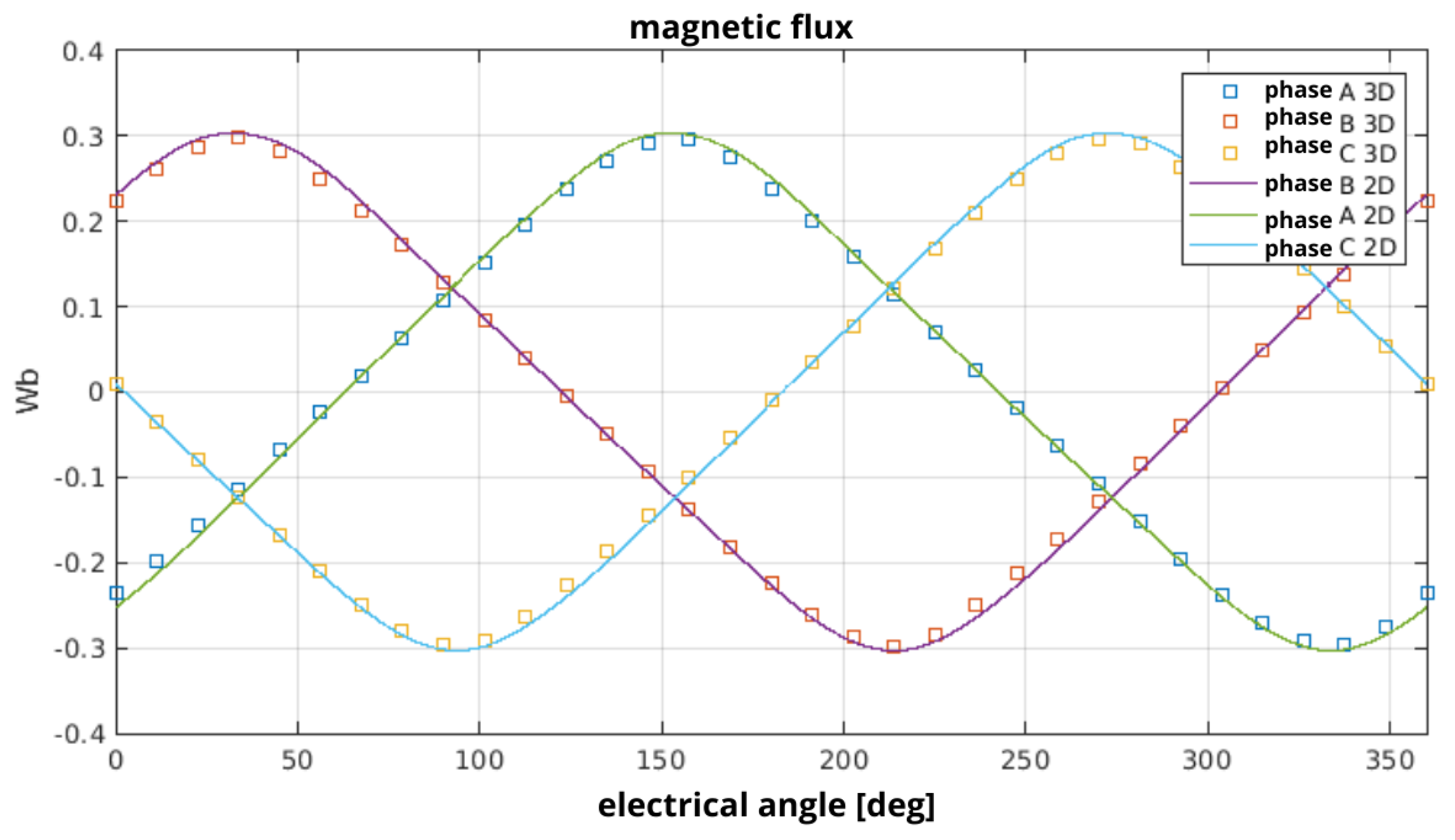
Figure 10 present a comparison of magnetic flux waveforms obtained with 3D and simplified 2D FEM computations.
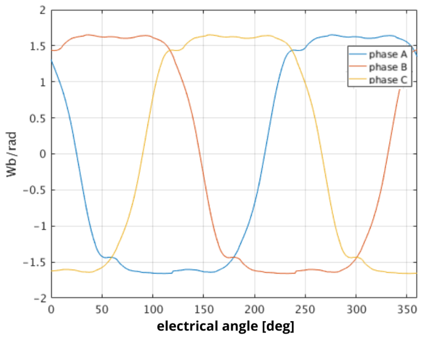
The Back-EMF waveforms are determined by calculating the derivatives of magnetic fluxes with respect to the rotor position angle θ . The results presented in Figure 11 can be compared with these in Figure 6, which are obtained using full 3D FEM analysis.

5. Brief Description of the Considered Control System

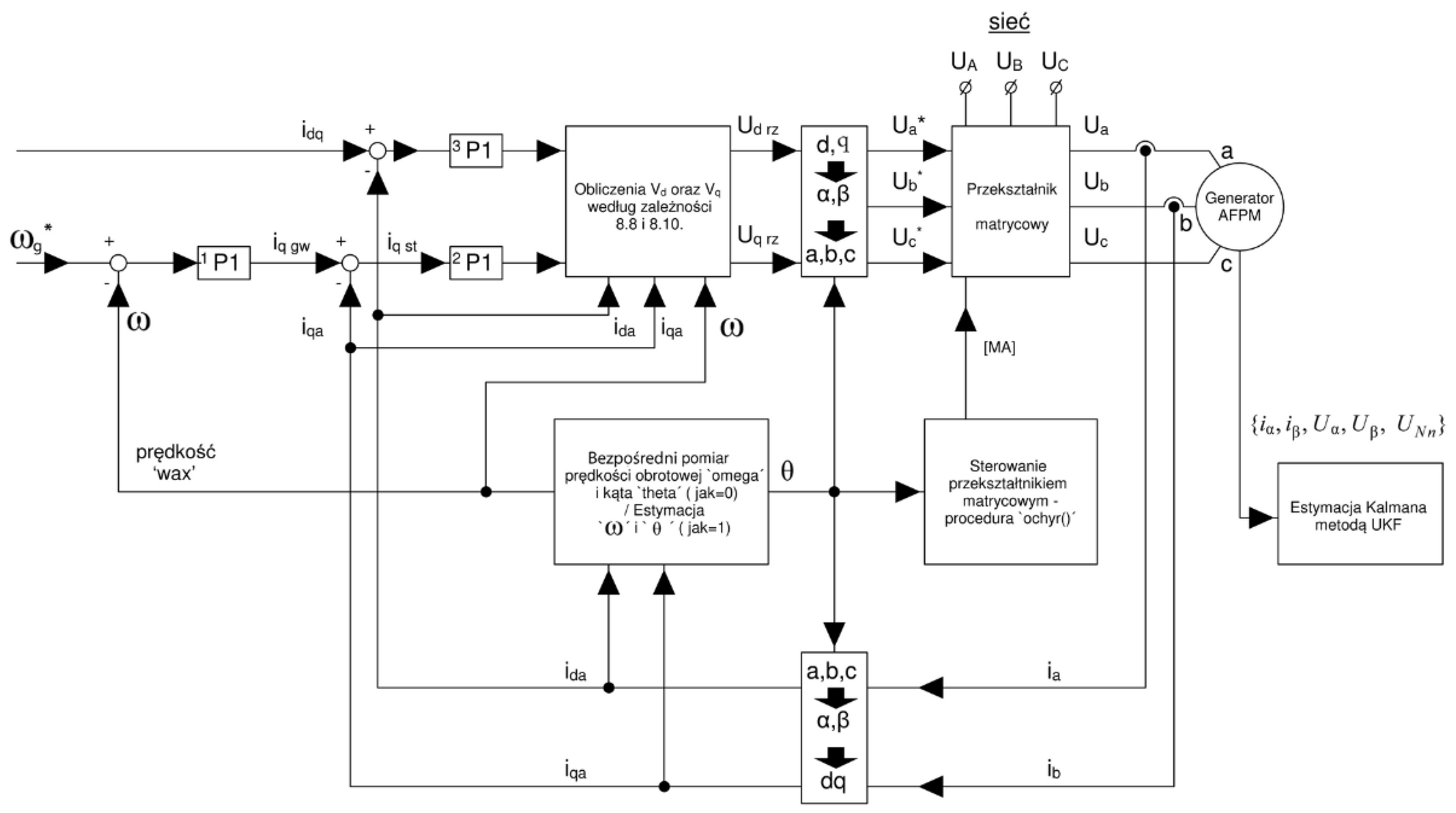
In this section, we present a control system capable of taking advantage of the features of the designed construction in order to estimate current values of working parameters ( ω and θ ) and to use them in the control process. Figure 12 presents an overall schema of the control system. A detailed description of the methods implemented in block “Estimation / measurements block” is presented in the next section. The description of methods implemented in a “Matrix converter controller” is beyond the scope of this paper.
The control system uses stator voltage components expressed in d q reference frame. In each time step, these components denoted in Figure 12 as U d r z and U q r z are computed, and after transformation to the natural reference frame, they are generated by the matrix converter to supply stator winding. The proper values of U d r z and U q r z are determined on the basis of the stator voltage equations formulated as shown in (5).
U d = R i d + ω · Ψ M d θ p · L · ω · i q + V d U q = R i q + ω · Ψ M q θ + p · L · ω · i d + V q V d = L · d d t i d k i d ( i d g i d a ) V q = L · d d t i q k i q ( i q g i q a )
where V d   a n d   V q are the voltage drops across the stator inductance L. These voltages are proportional to the derivatives of the corresponding currents i d and i q . They are approximated by the differences between the reference i d g , i q g w and actual i d a , i q a currents.
  • i d g —reference value for component d of stator current;
  • i q g w —reference value for component q of stator current;
  • k i d and k i q —proportionality coefficients;
  • i d a —instantaneous value of component d of stator current;
  • i q a —instantaneous value of component q of stator current.
The i d g = 0 reflects a lack of current excitation. The q component of the stator current is determined by the PI regulators in accordance with (6)
i q g w = k ω ( ω g ω ) k θ ( ω g ω ) d t + q c o e f ( ω g ω ) / q t o r q
where k ω , k θ , and q c o e f are well known as PI regulator coefficients. The last term ( ω g ω ) / q t o r q describes the relation between the desired change of the rotational speed and the value of electromagnetic torque needed to obtain it. The value of q t o r q coefficient is computed by using (7)
T g = i d · Ψ M d θ + i q · Ψ M q θ .

6. The Proposed Method for Estimation of Rotor Rotation Angle and Speed of the Designed Machine on the Basis of the Output Voltage

The proposed method of rotor angular speed estimation ω and the angle of rotation θ makes use of the Jacobian matrix [39,40] formulated according to the following dependency (8). The values of magnetic flux derivatives from permanent magnets coupled with stator winding are expressed in a time-invariant system α , β . After multiplication by the generator rotational speed ω , they provide constituents of the induced voltage.
J = ( ω · Ψ M α θ ) ω ( ω · Ψ M α θ ) θ ( ω · Ψ M β θ ) ω ( ω · Ψ M β θ ) θ ( ω · Ψ M 0 θ ) ω ( ω · Ψ M 0 θ ) θ
The value of ω · Ψ M 0 θ = U N n is the zero component of voltages of machine phases. In a three-wire system, it needs to be measured between the generator star connection point and the artificial zero passage point from phase voltages or voltages that supply the generator. It may also be computed as the zero component from the measured generator phase voltages. Thus, U N n should be treated as the value that is known accurately from the measurement.
The process of estimating the rotational speed ω and the angle of rotation θ is iterative, and it is based on determining adjustments Δ ω E s t = ω E s t k ω E s t k 1 and analogously defined Δ θ E s t on the basis of solving the dependency (9).
ω · ( Ψ M α θ ) r e f ω · ( Ψ M β θ ) r e f U N n r e f ω · ( Ψ M α θ ) ω · ( Ψ M β θ ) U N n = ( ω · Ψ M α θ ) ω ( ω · Ψ M α θ ) θ ( ω · Ψ M β θ ) ω ( ω · Ψ M β θ ) θ ( ω · Ψ M 0 θ ) ω ( ω · Ψ M 0 θ ) θ Δ ω E s t Δ θ E s t
The dependency (9) is an overdetermined system of algebraic linear equations b ¯ = A x ¯ . The value of the vector of unknowns x ¯ is 2 × 1 , while the matrix A has the value of 3 × 2 . In order to solve the equation system, it is multiplied by A T . This assures the conformance of the system main matrix ( A T · A ) and the vector of x ¯ . Then, the equation system is solved. Such a solution has a form of residuum value minimization R ¯ = A x ¯ b ¯ . Strictly speaking, it is the operation of minimizing the value of R ¯ T · R ¯ ; thus, such a solution is often called a solution of the smallest squares. In this case, the value R ¯ is a vector of the value of 3 × 1 . In the next part, the estimated vector of generator condition in the form provided by the dependency (10) is defined.
X ¯ E s t = ω · Ψ M α θ ω · Ψ M β θ i α i β
whereby the currents i α and i β are determined through a transformation to the system of α β of real, measured phase currents of the generator { i a , i b , i c } . On the basis of these values, expressed in the system of α β , the estimated value of the generated electromagnetic torque is determined according to the dependency (11).
T E s t = i α · Ψ M α θ + i β · Ψ M β θ
In the next step, the derivatives of the estimated parameters are determined, namely the speed ω E s t and the angle of rotation θ E s t . These values are described by the dependencies of (12)
d d t ω E s t = 1 J ( T E s t B · ω E s t T L ) d d t θ E s t = ω E s t
where T L is the generator load torque, and it is an unknown value. In the described process of generator performance parameter estimation, the assumption that was adopted is that T L = 0 . The variability of the estimated vector of generator condition d d t X ¯ E s t is determined by using the first two rows of Jacobian matrices (8) and voltage equations in the system of α β in the way defined by the dependency (13)
d d t [ X ¯ E s t ] = d d t ω · Ψ M α θ ω · Ψ M β θ i α i β = ( ω · Ψ M α θ ) ω · d d t ω E s t + ( ω · Ψ M α θ ) θ · ω E s t ( ω · Ψ M β θ ) ω · d d t ω E s t + ( ω · Ψ M β θ ) θ · ω E s t 1 L ( U α R · i α E s t ω E s t · ( Ψ M α θ ) E s t ) 1 L ( U β R · i β E s t ω E s t · ( Ψ M β θ ) E s t )
where U α and U β are set values of components α and β of the voltages on generator terminals, and the values ω E s t · ( Ψ M α θ ) E s t and ω E s t · ( Ψ M β θ ) E s t are component elements of the vector X ¯ E s t ( 1 : 2 ) from the equation. The derivatives of speed ω and angle θ that appear in the first two rows of the system of Equation (13) appear directly in the first two rows of the matrix J from Equation (8).
The value of the vector of the estimated generator condition in the consecutive time step of the dynamics simulation is determined numerically, according to the Eulerian equation:
ω · Ψ M α θ ω · Ψ M β θ i α i β E s t t + Δ t = ω · Ψ M α θ ω · Ψ M β θ i α i β E s t t + d d t Ψ M α θ Ψ M β θ i α i β E s t + e k 1 0 0 e k 2 e k 3 0 0 e k 4 · i α i α E s t i β i β E s t · Δ t
where { e k 1 , e k 2 , e k 3 , e k 4 } are estimation coefficients (their values were selected with the trial and error method through numerous simulation studies), while i α , i β are constituent elements of stator currents taken from measurements.

7. Results of Simulation Studies of Functioning of the Proposed Method of Generator Performance Parameter Estimation

Magnetic flux distributions from permanent magnets coupled with stator winding were used in the simulation program together with their derivatives, whose waveforms in the function of rotational angle were determined on the basis of machine 3D models, as described in the third section. In the calculations included hereafter, these values, similarly to the systems of phase winding currents, are represented according to Fourier distribution, by the assumed set of the biggest 8 harmonic components. The computational procedure is performed by simultaneous consideration of a set of selected harmonic components, the number of which may be assumed in any given way [41]. In order to determine complex equations for the origin of the values described by a set of harmonic components, a toolbox of symbolic computations in the MATLAB environment was applied. Then, these dependencies were filled with numerical values. This way, a set of ordinary differential equations was created, which was solved numerically. Computations of generator dynamics were done in a coordinate system connected with the rotating rotor.
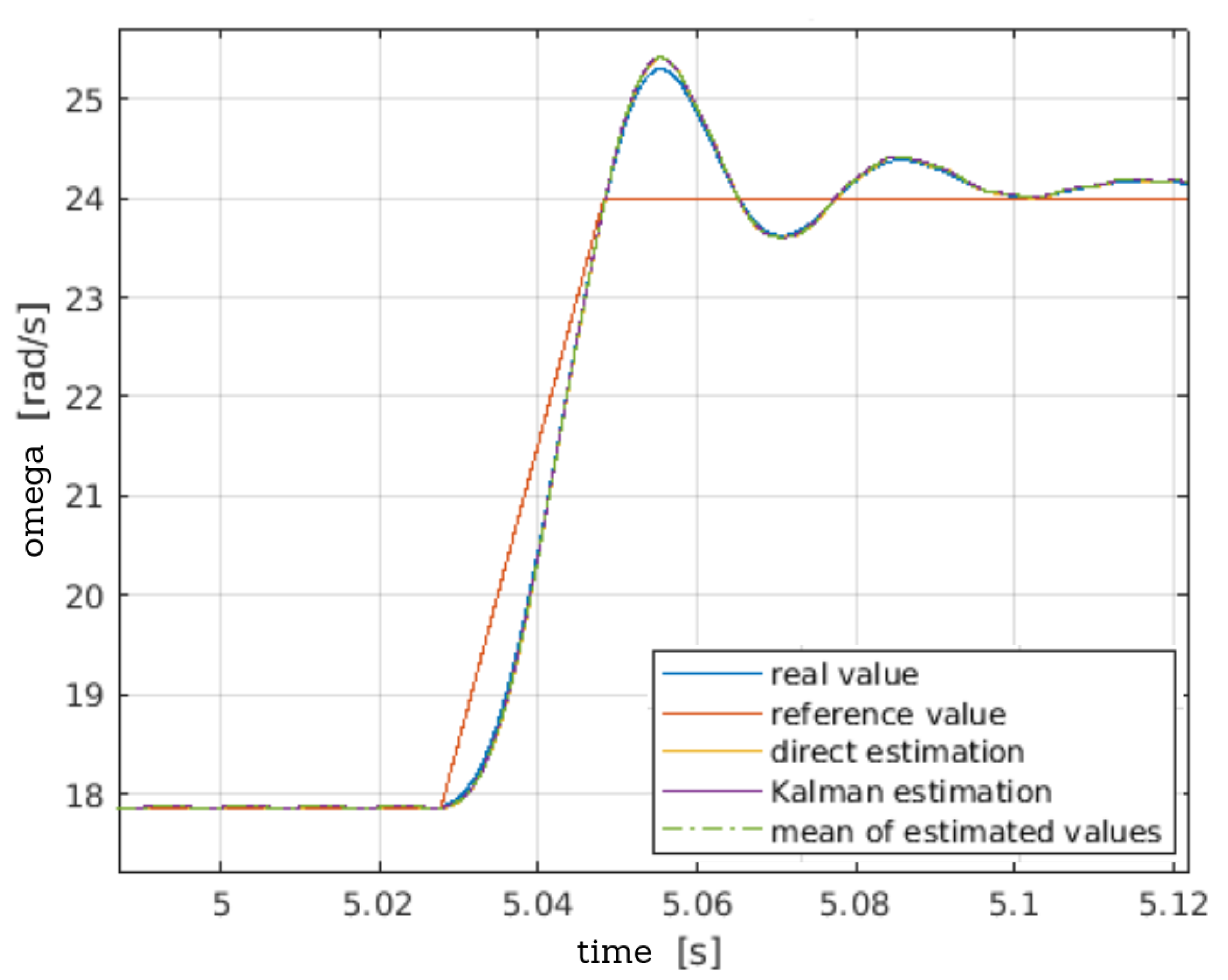
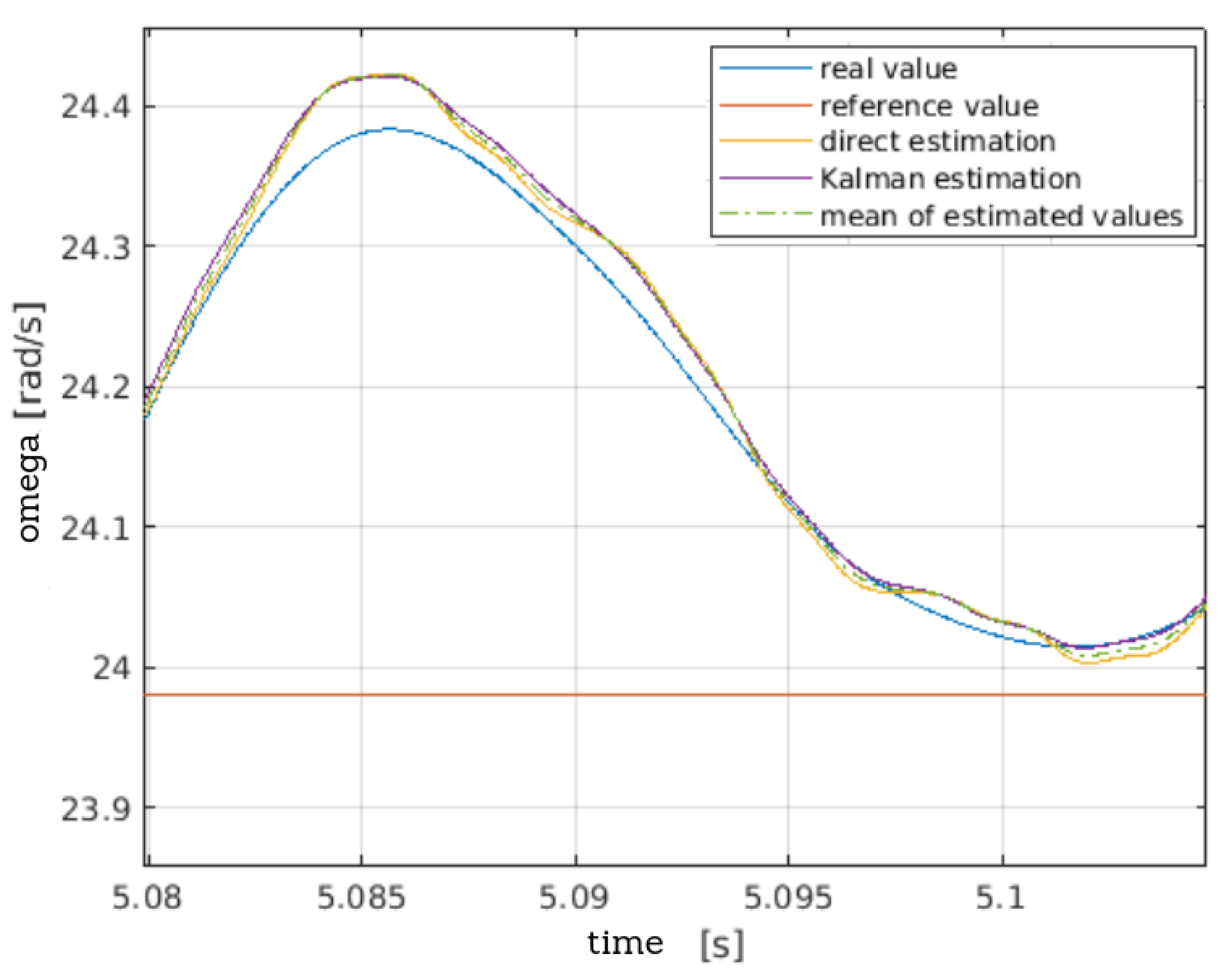
In order to assess the estimation quality provided by the proposed method, a simulation study was performed for generator performance controlled by means of a control system, whose structure and way of working are beyond the scope of this article. Additionally, the estimation of generator performance parameters was done, for comparative purposes, by using Kalman filter [42,43,44,45]. This procedure will be presented in a separate work. Figure 13 presents a comparison of waveforms of the real value of generator rotor rotational speed, with results of estimation done with the direct method described above and the method utilizing Kalman filter, in the case of a change of value of a given rotational speed.
The acquired results prove that both methods provide very high accuracy of estimation of the rotor rotational speed value in dynamic states. For the purpose of further assessment of the accuracy of results provided by the proposed method of direct estimation, it is necessary to take a closer look at the results of simulation. Figure 14 presents results of the same computations, enabling to approximately assess the behavior of the estimated values with regard to the real values of rotor rotational speed.
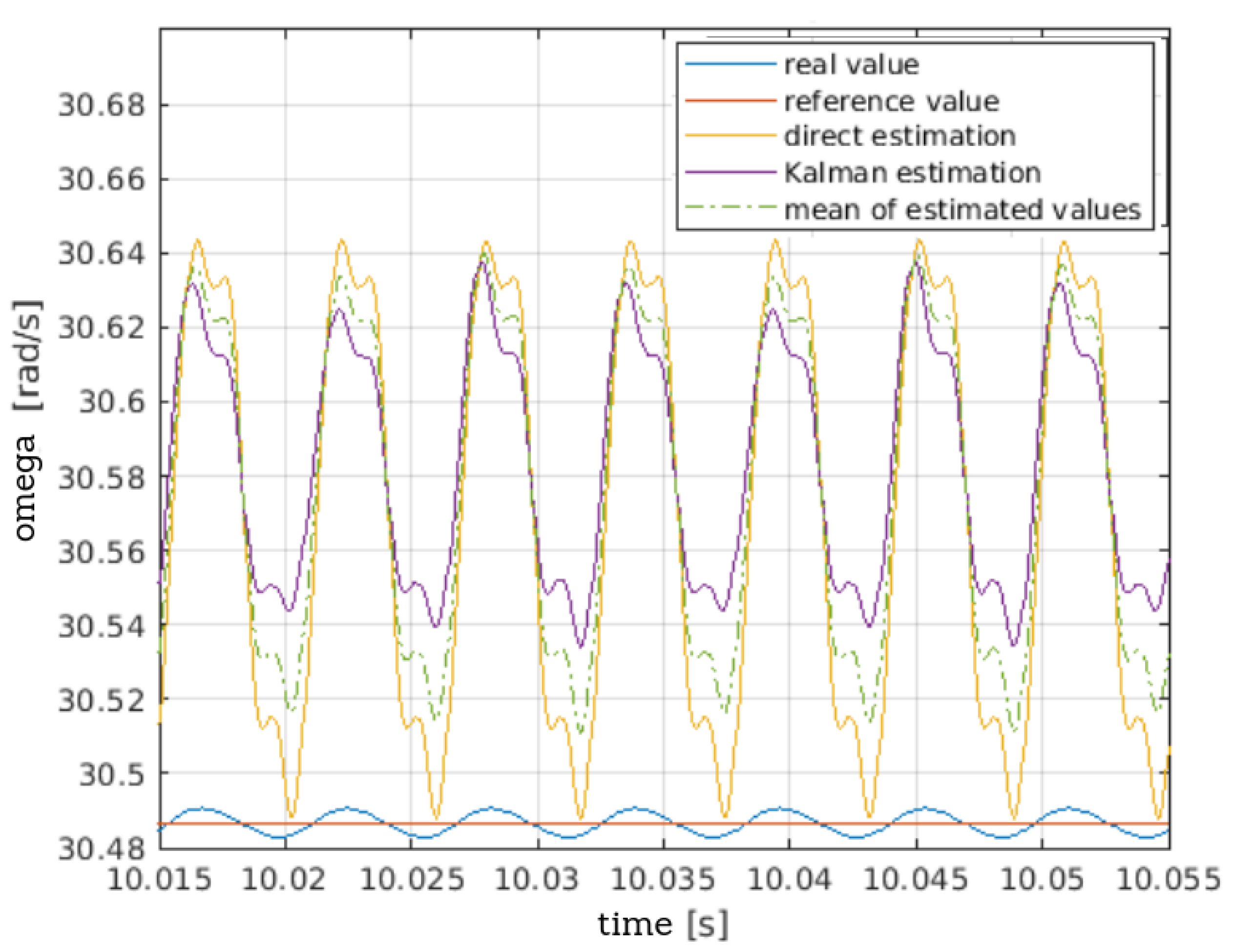
The acquired results indicate that both in the case of utilizing Kalman filter and the proposed method of direct estimation, the variability of the value of rotational speed is slightly overestimated in dynamic states. None of the compared estimation methods exhibit a greater tendency to error in this respect. Figure 15 presents a comparison of the estimation results of the machine rotational speed in the case of stabilization of its performance after a change in the value of the given rotational speed.
The acquired results indicate that both in the case of utilizing Kalman filter and the proposed method of direct estimation, the variability of the value of rotational speed is slightly overestimated in dynamic states. None of the compared estimation methods exhibit a greater tendency to error in this respect. Figure 15 presents a comparison of estimation results of the machine rotational speed in the case of stabilization of its performance after a change in the value of the given rotational speed.
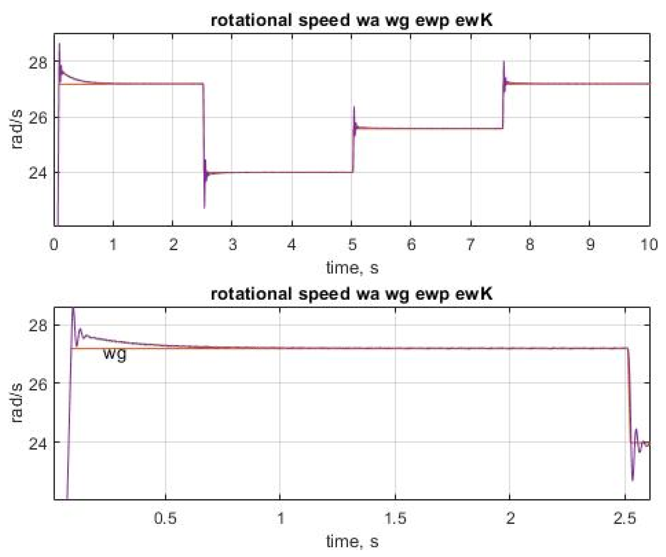
To better clarify the capabilities of the proposed methods, we performed calculations with the time-varying speed of the wind turbine–generator set. In this way, we checked the estimation indices. In Figure 16, we present the velocity waveforms—reference, actual, and estimated.
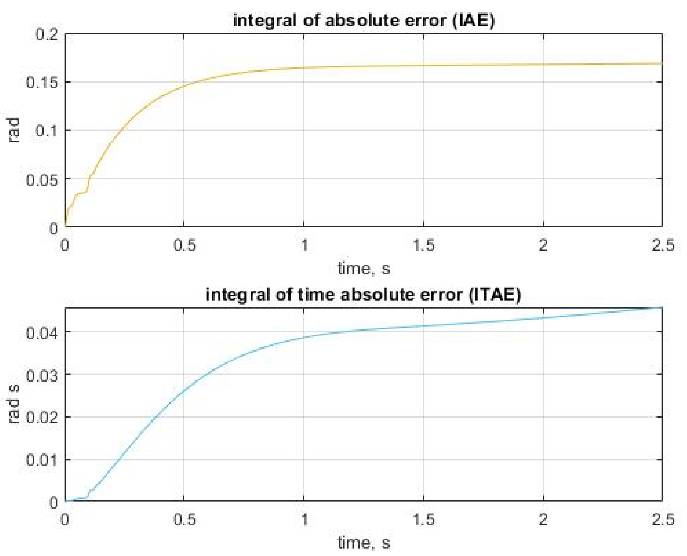
Figure 16 shows that the quality of the speed estimation is good. In Figure 17, we present the estimation results of the rotational speed with quantitative performance analysis utilizing the criteria, encompassing integral of absolute error (IAE) and integral of time absolute error (ITAE).
The presented waveforms indicate the good quality of the control of the wind turbine–generator system and the good quality of the velocity estimation proposed by the method in Section 6 and using the UKF filtering.

8. Conclusions

The proposed innovative construction of the AFPM machine, according to the design brief, is characterized by the shape of induced voltage that enables its use in the process of estimating rotor rotational speed and the position angle. This is ensured by a significant amount of the third harmonic component in the derivative waveform of the magnetic flux from permanent magnets in the angle of rotation. Simultaneously, the proposed construction ensures a low content of other higher harmonic components, which is a beneficial effect. The proposed method of machine performance parameter estimation makes use of induced voltages and machine phase currents that are provided in measurements. This is an iterative computational process based on a simple concept of solving an overestimated system of linear equations in the sense of the smallest squares, making use of numerical approximation of the solution of a set of differential equations. The obtained computational results confirm that the proposed method provides equally good results as a much more complicated estimation process performed by using the UKF type Kalman filter. The proposed regulation system provides a possibility to make use of these estimations in the control process. The performed simulations show that it can give satisfying results; however, it needs to be pointed out that determining values of estimator coefficients (presented in Equation (14)) providing optimal performance of the proposed estimator is considered as an open scientific issue.

Author Contributions

Conceptualization, L.G. and A.S.; methodology, L.G. and A.S.; software A.S., M.G.; validation, L.G., M.G. and A.S.; formal analysis, L.G., M.G.; investigation, L.G., A.S.; writing—original draft preparation L.G. and A.S.; writing—review and editing A.S.; funding acquisition, L.G. All authors have read and agreed to the published version of the manuscript.

Funding

This project is financed by the Minister of Education and Science of the Republic of Poland within the “Regional Initiative of Excellence” program for years 2019–2022. Project number 027/RID/2018/19, amount granted 11 999 900 PLN. The article was presented during 16th International Conference Selected Issues of Electrical Engineering and Electronics WZEE 2021 (Rzeszow September 2021).

Institutional Review Board Statement

Not applicable.

Informed Consent Statement

Not applicable.

Data Availability Statement

Not applicable.

Conflicts of Interest

The authors declare no conflict of interest.

References

  1. Ferraro, L.; Caricchi, F.; Capponi, F.G.; Donato, G. Axial-flux PM starter/alternator machine with a novel mechanical device for extended flux weakening capabilities. In Proceedings of the Conference Record of the 2004 IEEE Industry Applications Conference, Seattle, WA, USA, 3–7 October 2004. [Google Scholar]
  2. Neveen, K.S.; Mobi, M.; Karthikeyan, N.; Hossain, J. Development of Permanent Magnet Axial Flux Generator for Small Wind Turbines. In Proceedings of the IEEE International Conference on Circuits and Systems ICCS, Thiruvananthapuram, India, 20–21 December 2017. [Google Scholar] [CrossRef]
  3. Yang, Y.-P.; Xing, X.-Y.; Liang, J.Y. Design and application of axial-flux permanent magnet wheel motors for an electric vehicle. In Proceedings of the IEEE International Conference Conference: AFRICON, AFRICON ’09, Nairobi, Kenya, 23–25 September 2009. [Google Scholar] [CrossRef]
  4. Yang, Y.P.; Lee, C.H.; Hung, P.C. Multi-objective optimal design of an axial-flux permanent-magnet wheel motor for electric scooters. IET Electr. Power Appl. 2014, 8, 1–12. [Google Scholar] [CrossRef]
  5. Zhao, J.; Han, Q.; Dai, Y.; Hua, M. Study on the Electromagnetic Design and Analysis of Axial Flux Permanent Magnet Synchronous Motors for Electric Vehicles. Energies 2019, 12, 3451. [Google Scholar] [CrossRef] [Green Version]
  6. Chan, T.F.; Lai, L.L. Axial Flux Permanent Magnet generator for a direct coupled wind turbine system. IEEE Trans. Energy Convers. 2007, 22, 86–94. [Google Scholar] [CrossRef]
  7. Rolak, M.; Kot, R.; Malinowski, M.; Goryca, Z.; Szuster, J.T. Generators with permanent magnets used in small wind power plants. In Proceedings of the 2015 Selected Problems of Electrical Engineering and Electronics (WZEE), Kielce, Poland, 17–19 September 2015. [Google Scholar] [CrossRef]
  8. Rolak, M.; Kot, R.; Malinowski, M.; Goryca, Z.; Szuster, J.T. Design of Small Wind Turbine with Maximum Power Point Tracking Algorithm. In Proceedings of the IEEE International Symposium on Industrial Electronics, Gdansk, Poland, 27–30 June 2011. [Google Scholar] [CrossRef]
  9. Pien, Y.; Shih, G.Y. Optimal Design of an Axial Flux Permanent Magnet Motor for an Electric Vehical Based on Driving Scenario. Energies 2016, 9, 285. [Google Scholar]
  10. Sabioni, C.L.; Riberio, M.; Vasconcelos, J.A. Robust Design of an Axial Flux Permanent Magnet Synchronous Generator Based on Many-Objective Optimization Approach. IEEE Trans. Magn. 2018, 54, 1–4. [Google Scholar] [CrossRef]
  11. Ojaghlu, P.; Vehedi, A. A New Axial Flux Permanet Magnet Machine. IEEE Trans. Magn. 2018, 54, 1–6. [Google Scholar] [CrossRef]
  12. Taran, N.; Rallabandi, V.; Ionel, D.M.; Heins, G. A Comparative Study of Coreless and Conventional Axial Flux Permanent Magnet Synchronous Machine for Low and High Speed Operation. In Proceedings of the IEEE Energy Conversion Congress and Expo (ECCE 2017), Cincinnati, OH, USA, 1–5 October 2017. [Google Scholar] [CrossRef]
  13. Mahmoudi, A.; Rahim, N.A.; Hew, W.P. Axial-flux permanent-magnet machine modeling, design, simulation and analysi. Sci. Res. Essays 2011, 6, 2525–2549. [Google Scholar]
  14. Gieras, F.J.; Wang, R.J.; Kampeer, M.J. Axial Flux Permanent Magnet Brushless Machines, 2nd ed.; Springer: Berlin/Heidelberg, Germany, 2008. [Google Scholar]
  15. Huang, R.; Liu, C.; Song, Z.; Zhao, H. Design and Analysis of a Novel Axial-Radial Flux Permanent Magnet Machine with Halbach-Array Permanent Magnets. Energies 2021, 14, 3639. [Google Scholar] [CrossRef]
  16. Kutt, F.; Blecharz, K.; Karkosiński, D. Axial-Flux Permanent-Magnet Dual-Rotor Generator for a Counter-Rotating Wind Turbine. Energies 2020, 13, 2833. [Google Scholar] [CrossRef]
  17. Ebrahimi, M.; Javadi, H.; Daghigh, A. Maximum power point tracking of a variable speed wind turbine with a coreless AFPM synchronous generator using OTC method. In Proceedings of the 8th Power Electronics, Drive Systems and Technologies Conference (PEDSTC), Mashhad, Iran, 14–16 February 2017. [Google Scholar] [CrossRef]
  18. Caricchi, F.; Crescimbini, F.; Honorati, O.; Bianco, G.L.; Santini, E. Performance of coreless-winding axial-flux permanent-magnet generator with power output at 400 Hz, 3000 r/min. IEEE Trans. Ind. Appl. 1998, 34, 1263–1269. [Google Scholar] [CrossRef] [Green Version]
  19. Radwan-Pragłowska, N.; Węgiel, T.; Borkowski, D. Modeling of Axial Flux Permanent Magnet Generators. Energies 2020, 13, 5741. [Google Scholar] [CrossRef]
  20. Wang, S.; Zhao, J.; Liu, T.; Hua, M. Adaptive Robust Control System for Axial Flux Permanent Magnet Synchronous Motor of Electric Medium Bus Based on Torque Optimal Distribution Method. Energies 2019, 12, 4681. [Google Scholar] [CrossRef] [Green Version]
  21. Pei, Y.; Wang, Q.; Bi, Y.; Chai, F. A Novel Structure of Axial Flux, 2nd ed.; Springer: Berlin/Heidelberg, Germany, 2008. [Google Scholar]
  22. Tiegna, H.; Amara, Y.; Barakat, G. Study of Cogging Torque in Axial Flux Permanent Magnet Machines Using an Analytical Model. IEEE Trans. Magn. 2014, 50, 845–848. [Google Scholar] [CrossRef]
  23. Barmpatza, A.C.; Kappatou, J.C. Study of a Combined Demagnetization and Eccentricity Fault in an AFPM Synchronous Generator. Energies 2020, 13, 5609. [Google Scholar] [CrossRef]
  24. Sagar, S.V.; Joseph, K.D. Speed Estimation Algorithms for Sensorless Control of PMSM. In Proceedings of the International Mutli-Conference on Automation, Computing, Communication, Control and Compressed Sensing (iMac4s), Kottayam, Kerala, India, 22–23 February 2013. [Google Scholar] [CrossRef]
  25. Chen, G.; Yang, S.; Hsu, Y.; Li, K. Position and Speed Estimation of Permanent Magnet Machine Sensorless Drive at High Speed Using an Improved Phase-Locked Loop. Energies 2017, 10, 1571. [Google Scholar] [CrossRef] [Green Version]
  26. Yousfi, D.; Darkawi, A. Comparison of two Position and Speed Estimation Techniques used in PMSM Sensorless Vector Control. In Proceedings of the 4th IET Conference on Power Electronics, Machines and Drives, PEMD 2008, York, UK, 2–4 April 2008. [Google Scholar] [CrossRef] [Green Version]
  27. Badini, S.S.; Verma, V. MRAS-Based Speed and Parameter Estimation for a Vector Controlled PMSM Drive. Electrica 2020, 20, 28–40. [Google Scholar] [CrossRef]
  28. Liu, H.; Li, G. Rotor Position and Speed Estimation Method for Magnetically Suspended PMSM Based on Modified Sliding Mode Observer. In Proceedings of the International Conference on Mechatronics, Control and Automation Engineering (MCAE), Bangkok, Thailand, 24–25 July 2016. [Google Scholar] [CrossRef] [Green Version]
  29. Hijazi, A.; Sidhom, L.; Zgorski, A.; Shi, X.L. On speed estimation of permanent magnet synchronous motor using adaptive robust position observer and differentiator. In Proceedings of the 11th IFAC International Workshop on Adaptation and Learning in Control and Signal Processing (11 IFAC), Caen, France, 3–5 July 2013. [Google Scholar] [CrossRef]
  30. Sathans, O.M. Sliding-mode observer for estimating position and speed and minimizing ripples in rotor parameters of PMSM. In Proceedings of the 2nd International Conference on Inventive Systems and Control (ICISC), Coimbatore, India, 19–20 January 2018. [Google Scholar] [CrossRef]
  31. Białoń, T.; Niestrój, R.; Pasko, M.; Lewicki, A. Gains selection of non-proportional observers of an induction motor with dyadic methods. In Proceedings of the 13th Selected Issues of Electrical Engineering and Electronics (WZEE), Rzeszow, Poland, 4–8 May 2016. [Google Scholar] [CrossRef]
  32. Utrata, G.; Rolek, J.; Kapłon, A. Induction motor electromechanical quantities estimation based on the inductance frequency characteristic—Simulation studies. In Proceedings of the 16th International Conference on Computational Problems of Electrical Engineering, Lviv, Ukraine, 2–5 September 2015. [Google Scholar] [CrossRef]
  33. Gołębiowski, M.; Gołębiowski, L.; Smoleń, A.; Mazur, D. Direct Consideration of Eddy Current Losses in Laminated Magnetic Cores in Finite Element Method (FEM) Calculations Using the Laplace Transform. Energies 2020, 13, 1174. [Google Scholar] [CrossRef] [Green Version]
  34. Credo, A.; Tursini, M.; Villani, M.; Lodovico, C.D.; Orlando, M.; Frattari, F. Axial Flux PM In-Wheel Motor for Electric Vehicles: 3D Multiphysics Analysis. Energies 2021, 14, 2107. [Google Scholar] [CrossRef]
  35. Bumby, J.R.; Martin, R.; Mueller, M.A.; Spooner, E.; Brown, N.L.; Chalmers, B.J. Electromagnetic design of axial-flux permanent magnet machines. IEE Proc.-Electr. Power Appl. 2004, 151, 151–160. [Google Scholar] [CrossRef]
  36. Gołębiowski, L.; Gołębiowski, M.; Mazur, D.; Smoleń, A. Analysis of axial flux permanent magnet generator. COMPEL Int. J. Comput. Math. Electr. 2019, 38. [Google Scholar] [CrossRef]
  37. Smoleń, A.; Gołębiowski, M. Computationally efficient method for determining the most important electrical parameters of axial field permanent magnet machine. Biulletin Pol. Acad. Sci. Tech. Sci. 2018, 66, 947–959. [Google Scholar]
  38. Smoleń, A.; Gołębiowski, L.; Gołębiowski, M.; Mazur, D. Computationally Efficient Method of Co-Energy Calculation for Transverse Flux Machine Based on Poisson Equation in 2D. Energies 2019, 12, 4340. [Google Scholar] [CrossRef] [Green Version]
  39. Zbranek, P.; Vesely, L. Nonlinear state estimation using interval computation in PMSM state observer simulation. In Proceedings of the International Conference on Autonomous and Intelligent Systems, AIS, Povoa de Varzim, Portugal, 21–23 June 2010. [Google Scholar] [CrossRef]
  40. Li, X.; Li, S. Extended state observer based adaptive control scheme for PMSM system. In Proceedings of the Proceedings of the 33rd Chinese Control Conferences, Nanjing, China, 28–30 July 2014. [Google Scholar] [CrossRef]
  41. Drabek, T.; Matras, A.; Skwarczyński, J. Analytical calculation of simulation of permanent magnet synchronous machine. Przegląd Elektrotechniczny 2009, 85, 9–12. [Google Scholar]
  42. Li, H.; Wang, Z. Sensorless Control for PMSM Drives Using the Cubature Kalman Filter based Speed and Flux Observer. In Proceedings of the IEEE International Conference on Electrical Systems for Aircraft, Railway, Ship Propulsion and Road Vehicles and International Transportation Electrification Conference (ESARS-ITEC), Nottingham, UK, 7–9 November 2018. [Google Scholar] [CrossRef]
  43. Zheng, Z.; Li, Y.; Fadel, M.; Xi, X. A Rotor Speed and Load Torque Observer for PMSM Based on Extended Kalman Filter. In Proceedings of the IEEE International Conference on Industrial Technology, Mumbai, India, 15–17 December 2006. [Google Scholar] [CrossRef]
  44. Chen, H.; Liu, B.; Qu, Y.; Zhou, X. Low speed control for PMSM based on reduced-order adaptive Kalman filter. In Proceedings of the 33rd Chinese Control Conference, Nanjing, China, 28–30 July 2014. [Google Scholar] [CrossRef]
  45. Gao, T.; Yang, Y.; Wang, J.; Zhou, Y.R.; Zhao, X.P. Rotor Position Estimation of Sensorless PMSM Based on Extented Kalman Filter. In Proceedings of the IEEE International Conference on Mechatronics, Robotics and Automation (ICMRA), Hefei, China, 18–21 May 2018. [Google Scholar] [CrossRef]
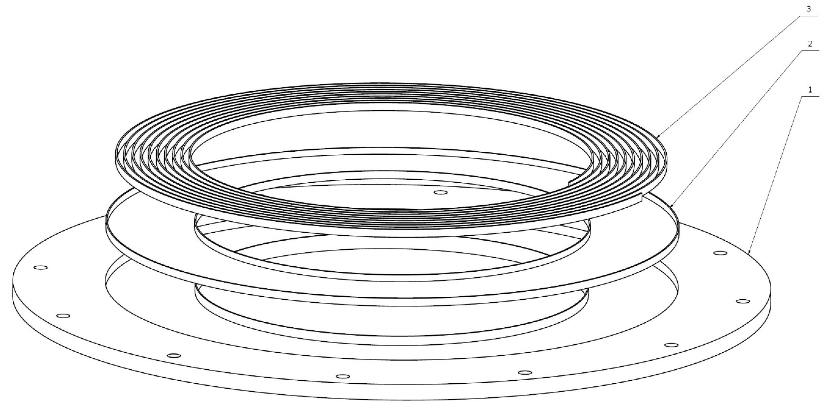
Figure 1. The structure of the rotor disc (the construction principle for the upper and the bottom discs is identical); 1—rotor disc, 2—low magnetic permeability coating, 3—channel filling.
Energies 15 00236 g001
Figure 2. Element of stator core comprised in the form of a set of sheets.
Energies 15 00236 g002
Figure 3. Position of elements included in the machine stator, seen from the top; 1—phase coil A, 2—phase coil B, 3—phase coil C, 4 or 5—magnetic material element that comprises the stator core.
Energies 15 00236 g003
Figure 4. Comparison of the finite element mesh acquired for the permissible energy error on the level of 1% (left) and 0.1 % (right).
Energies 15 00236 g004
Figure 5. Distribution of the flux induction vector on the cross-section area in the radial direction through the center of the front part of one of the coils.
Energies 15 00236 g005
Figure 6. Derivatives of magnetic fluxes from permanent magnets as a function of the rotation angle.
Energies 15 00236 g006
Figure 7. Amplitude spectrum of the derivative waveform in the angle of rotation from the magnetic flux of permanent magnets coupled with the A phase.
Energies 15 00236 g007
Figure 8. A simplified model of the proposed construction AFPM generator used to perform analytical computations of magnetic field distribution.
Energies 15 00236 g008
Figure 9. Magnetic field distribution obtained by using 2D FEM computation performed with a self-developed program.
Energies 15 00236 g009
Figure 10. Comparison of magnetic flux waveforms coupled with stator winding.
Energies 15 00236 g010
Figure 11. Derivatives of magnetic fluxes from permanent magnets as a function of the rotation angle—computed using a simplified 2D FEM approach.
Energies 15 00236 g011
Figure 12. Control system schema.
Energies 15 00236 g012
Figure 13. Comparison of estimation results of the rotational speed obtained with the direct method, with results acquired with Kalman filter.
Energies 15 00236 g013
Figure 14. Comparison of estimation results of the rotational speed obtained with the direct method, with results acquired with Kalman filter, behavior of the proposed estimator during overshooting—enlarged view.
Energies 15 00236 g014
Figure 15. Comparison of the rotational speed waveform of the generator with estimation results after reaching the steady state—enlarged view.
Energies 15 00236 g015
Figure 16. Simulated changes of rotational speed reference value compared with actual rotational speed and estimation results.
Energies 15 00236 g016
Figure 17. Quantitative performance analysis utilizing the criteria, encompassing integral of absolute error (IAE) and integral of time absolute error (ITAE) of the waveforms in Figure 16.
Energies 15 00236 g017
Table 1. Selected parameters of the proposed generator structure.
ParameterValueUnit
Rotor disc
Disc outside diameter465mm
Bottom disc inside diameter240mm
Upper disc inside diameter71mm
Disc thickness10mm
Distance between the discs (axial)31mm
Materialsteel s235[-]
Permanent magnets
Inside radius124mm
Outside radius172mm
Groove angle 30 mm
Thickness10mm
Distance between magnets (axial)15mm
Distribution radius101mm
Induced remanence B r 1.19T
Coercion intensity i H c 1.19T
Relative magnetic permeability μ r 1.0922[-]
Stator coils
Length in the radial direction89.8mm
Distribution radius101.7mm
Number of windings64[-]
Coil wire cross section1.2mm 2
Estimated length of the coil wire12.33m
The length of coil active part47.6mm
Winding cross-section
Width12mm
Height8mm
Publisher’s Note: MDPI stays neutral with regard to jurisdictional claims in published maps and institutional affiliations.