
A Review of Developments in Carbon-Based Nanocomposite Electrodes for Noninvasive Electroencephalography


Abstract
1. Introduction
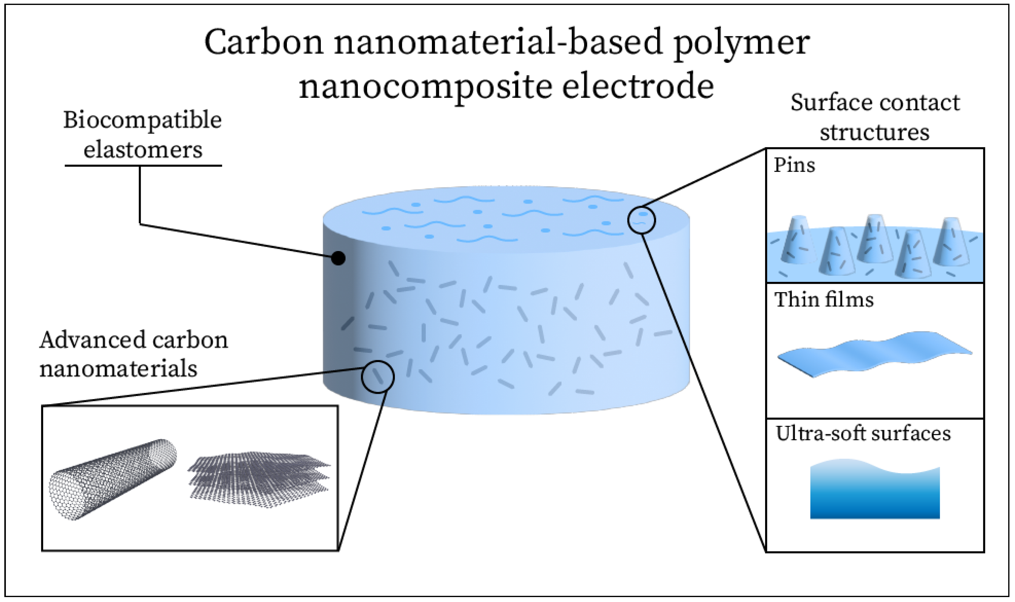
2. Electrode Design
2.1. Carbon Nanomaterials
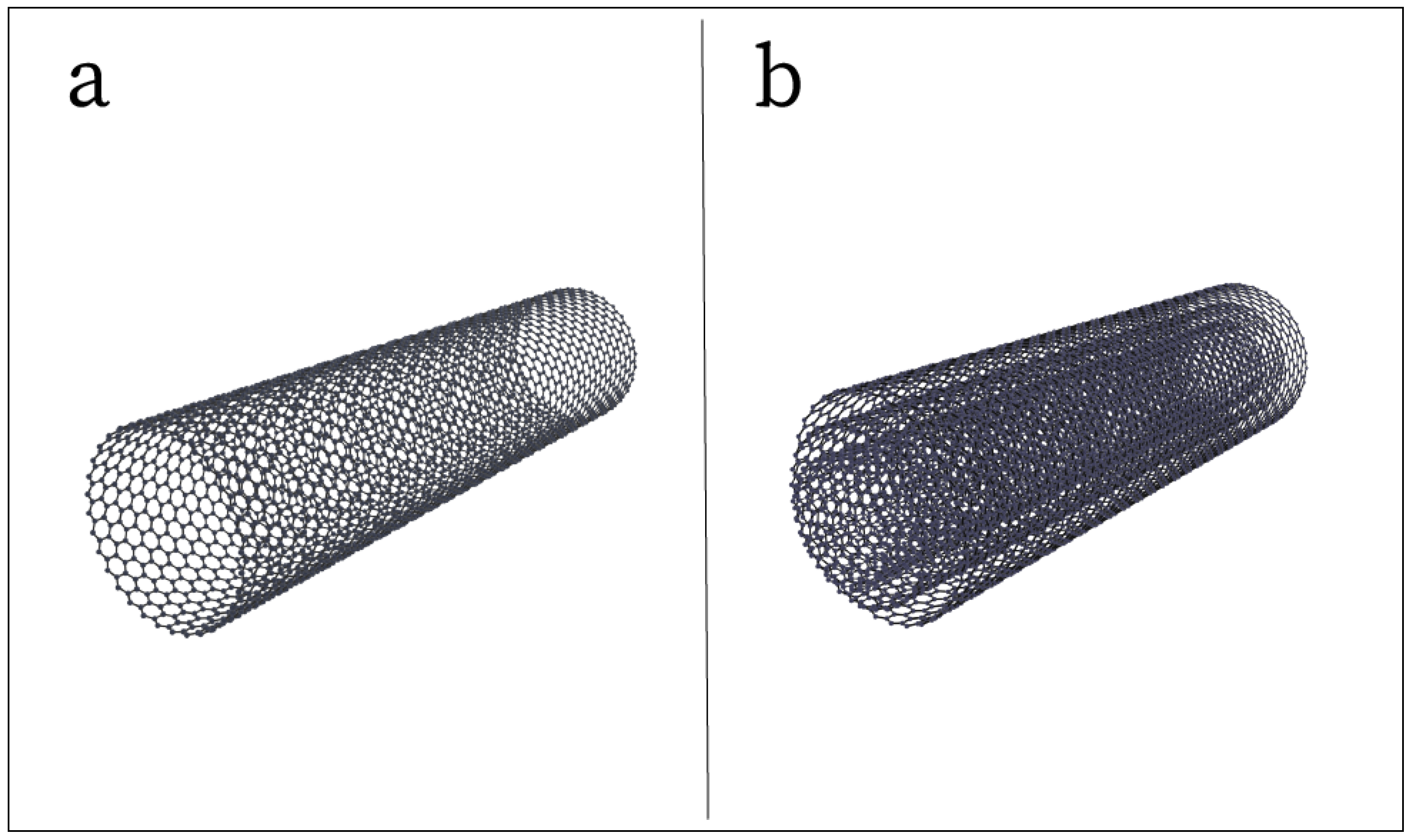
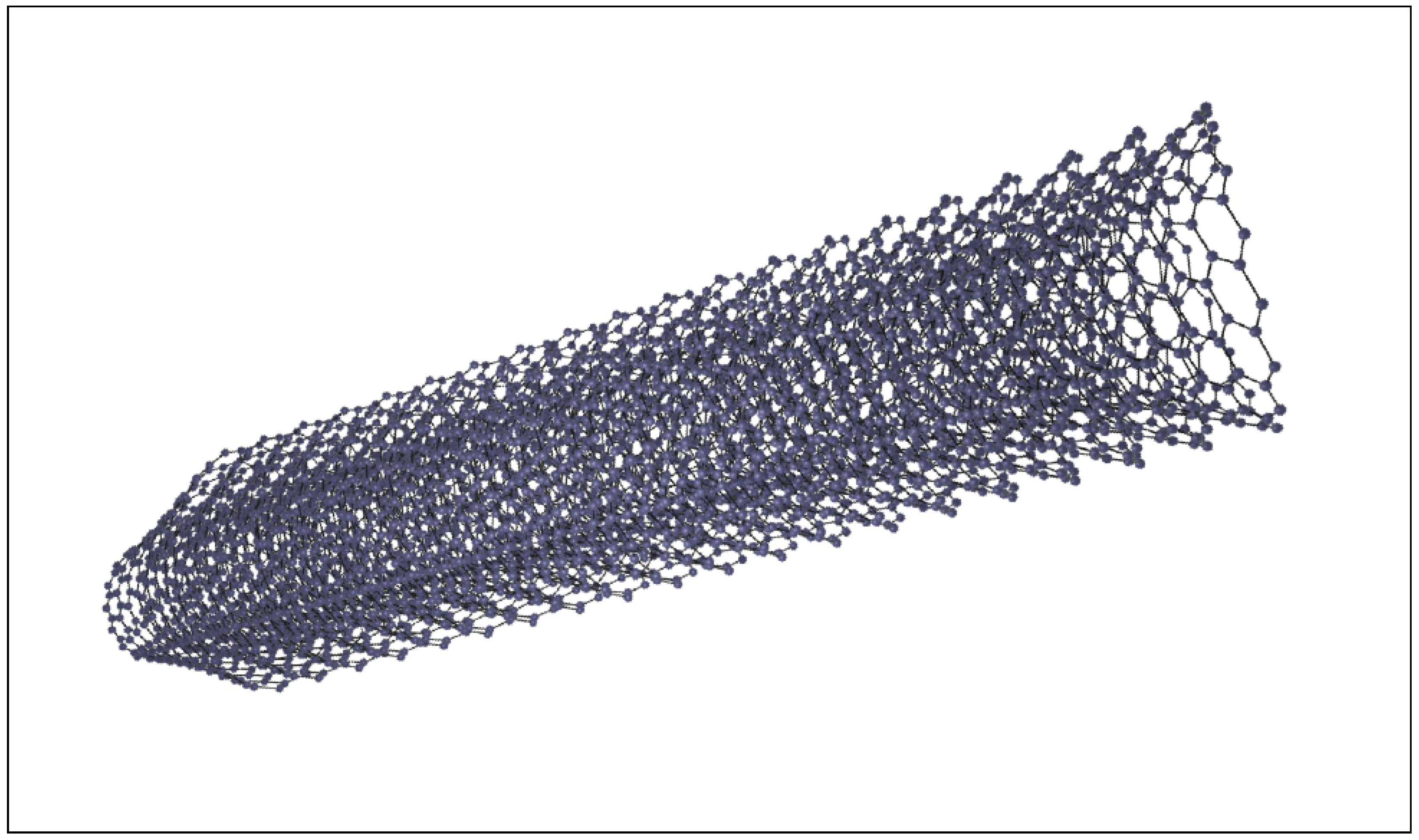
2.1.1. Carbon Nanotubes
2.1.2. Carbon Nanofibers
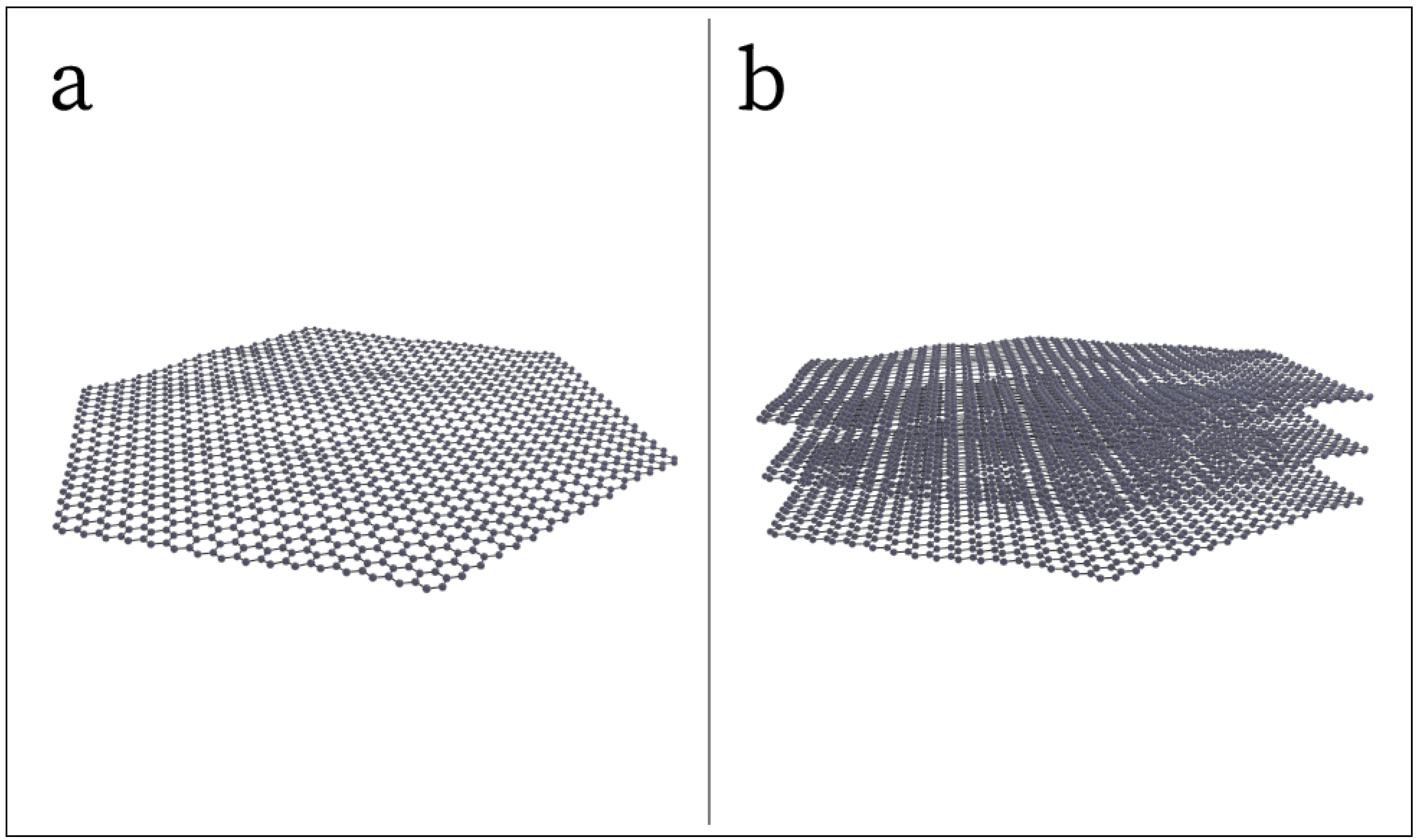
2.1.3. Graphene
2.1.4. Carbon Black
2.1.5. Carbon Fibers and Particles
2.2. Electrode Substrates
2.2.1. Elastic Polymers
2.2.2. Alternative Substrates
2.3. Surface Contact Structures
3. Electrode Properties
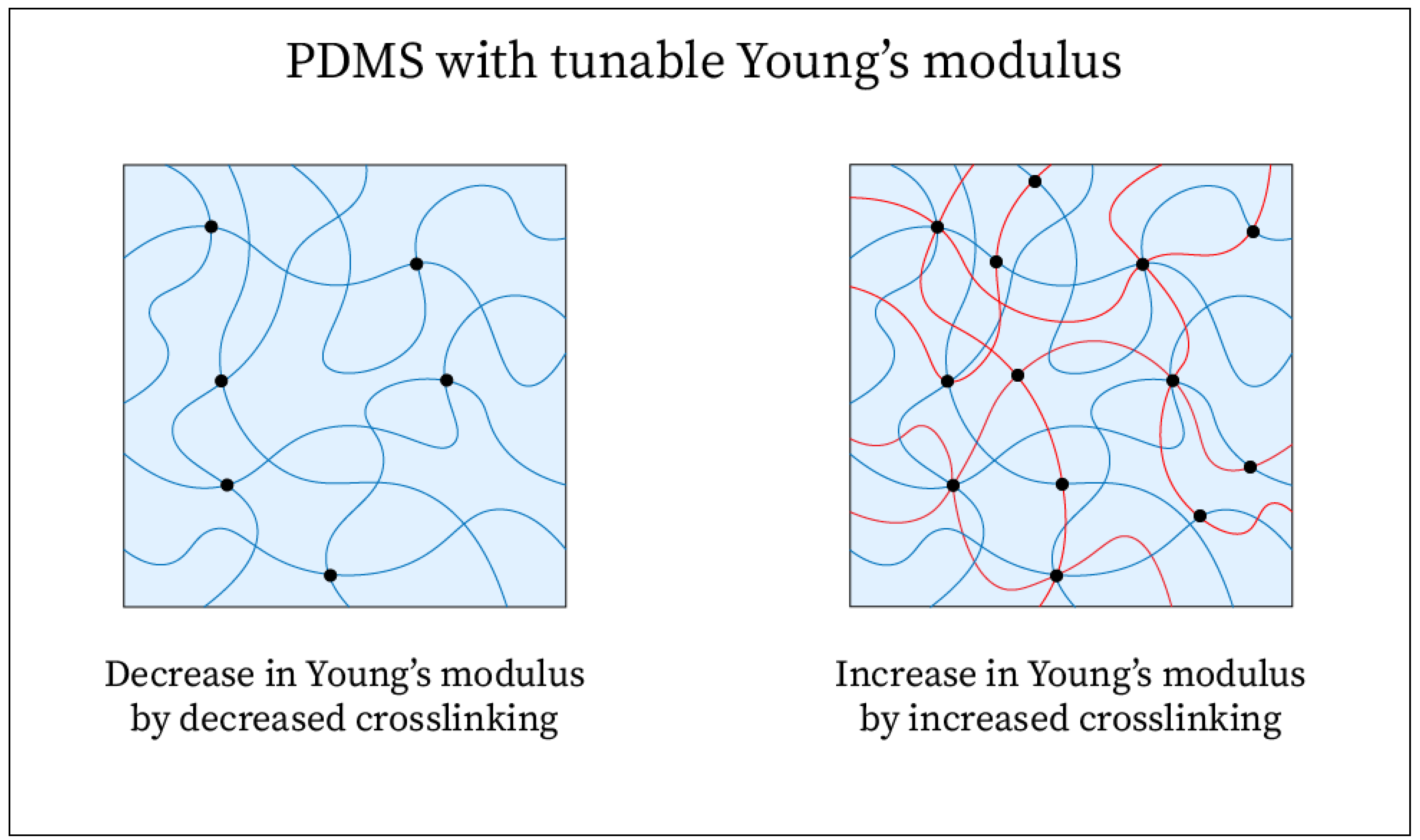
3.1. Mechanical Properties
3.2. Electrical Properties
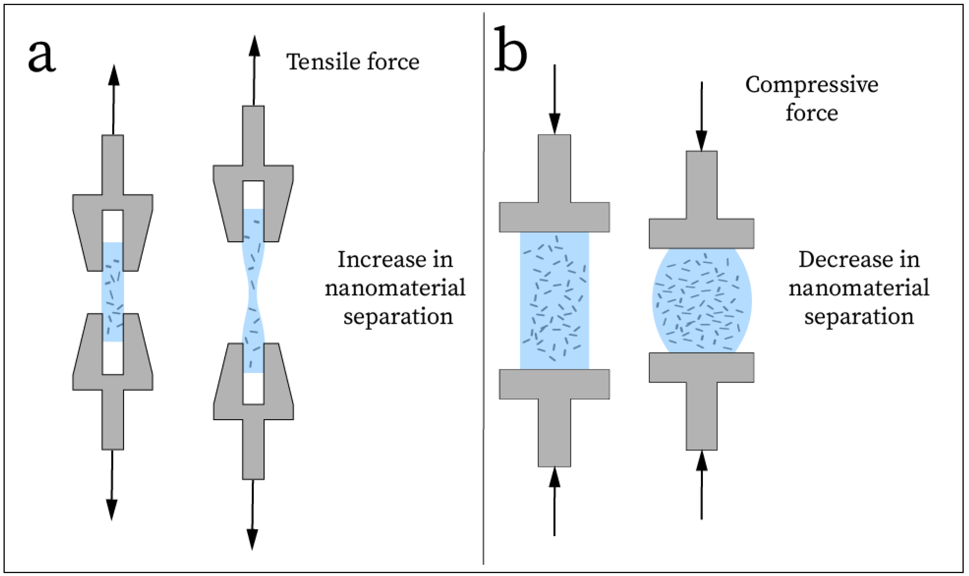
3.3. Strain Response

| Electrode Type | Resistance or Resistivity a | Skin-Contact Impedance b | Conductivity | Reference |
|---|---|---|---|---|
| Ag/CNT/PDMS Composite | 216–663 Ω/sq | - | 0.75–3.70 S/m | [41] |
| CNT/PDMS Thin-film | - | 800 kΩ at 10 Hz | 10–100 S/m | [39] |
| GPG Thin-film | 20.8 Ω/sq | 200 kΩ at 10 Hz | 2850–3727 S/m | [76] |
| SLPP Thin-film | 90–180 Ω/sq | 14.39 kΩ at 10 Hz | - | [40] |
| CMSA Composite | 1387 Ω/sq | 275 kΩ at 20 Hz | - | [15] |
| TCRE Composite | - | ∼10 kΩ at 10 Hz | - | [42] |
| PEDOT:PSS Composite | 0.2 Ω·m | 10 kΩ·cm2 at 10 Hz | - | [87] |
| ACNT Thin-film | 250–2000 Ω/sq | 500 kΩ at 50 Hz | 1.2 × 10⁴ S/m | [66] |
| Ag/CNT-GO-PDMS Composite | 9.66–14.3 kΩ | ∼15 kΩ at 8–13 Hz | - | [67] |
| FLG/TiO2 Wafer | 9.2–19.0 kΩ | - | - | [32] |
| CNT/aPDMS Composite | - | 309.8 kΩ at 10 Hz | - | [61] |
| AB/PDMS Composite | 10–100 kΩ | 271 kΩ at 100 Hz | - | [88] |
| SPRABE Thin-film | 108 Ω/sq | 100 kΩ at 10 Hz | - | [68] |
| EG/SiC Wafer | - | 155–325 kΩ at 50 Hz | - | [81] |
| BVNG Electrode | ∼15 kΩ | ∼5 kΩ at 10 Hz | - | [16] |
| LSG/PU Thin-film | 30–70 Ω/sq | ∼2.5 × 10⁴ kΩ at 50 Hz | - | [77] |
| Cu-TiO2-CNT@PDMS | 10.9–12.62 kΩ | <5 kΩ at 10 Hz | - | [33] |
| PTG Thin-film | 24–170 Ω/sq | 32 kΩ at 100 Hz | 2850–4142 S/m | [13] |
| EARtrodes composite | - | <60 kΩ at 10 Hz | - | [49] |
| rGO Textile | 14 kΩ/sq | ∼59 kΩ at 50 Hz | ∼0.33 S/m | [44] |
| EG Composite | 0.1–0.2 Ω·m | 128 kΩ at 10 Hz | - | [82] |
| GFG Composite | 150–275 Ω/sq | 2 × 10⁴ kΩ at 10 Hz | - | [79] |
| AgNW-GES Thin-film | 700 Ω | 100 kΩ at 10 Hz | - | [35] |
| rGO Thin-film | - | 600 kΩ at 20 Hz | - | [80] |
| TRGO/NM Thin-film | ∼40 Ω/sq | ∼20 kΩ at 4 Hz | - | [84] |
| GEMMPS Wafer | 30 Ω | ∼250 kΩ at 10 Hz | - | [14] |
| CNT/PDMS Composite | 0.1–100 kΩ | 0.005–1 kΩ at 10 Hz | - | [17] |
| AgNW/CNT Composite | - | ∼200 kΩ at 10 Hz | - | [37] |
| CF Composite | - | ∼200 kΩ at 20 Hz | 1–18 S/m | [50] |
| CF Bristles | - | 40–60 kΩ at 10 Hz | 250–1000 S/m | [38] |
3.4. Signal-to-Noise Ratio
4. Electrode Characterization
4.1. Biocompatibility
4.2. EEG Performance
5. Discussion and Future Opportunities
6. Conclusions
Author Contributions
Funding
Institutional Review Board Statement
Informed Consent Statement
Data Availability Statement
Acknowledgments
Conflicts of Interest
References
- Rdest, M.; Janas, D. Carbon Nanotube Wearable Sensors for Health Diagnostics. Sensors 2021, 21, 5847. [Google Scholar] [CrossRef] [PubMed]
- Wang, C.; Xia, K.; Wang, H.; Liang, X.; Yin, Z.; Zhang, Y. Advanced Carbon for Flexible and Wearable Electronics. Adv. Mater. 2019, 31, 1801072. [Google Scholar] [CrossRef]
- Nag, A.; Nuthalapati, S.; Mukhopadhyay, S.C. Carbon Fiber/Polymer-Based Composites for Wearable Sensors: A Review. IEEE Sens. J. 2022, 22, 10235–10245. [Google Scholar] [CrossRef]
- Erdem, O.; Derin, E.; Zeibi Shirejini, S.; Sagdic, K.; Yilmaz, E.G.; Yildiz, S.; Akceoglu, G.A.; Inci, F. Carbon-Based Nanomaterials and Sensing Tools for Wearable Health Monitoring Devices. Adv. Mater. Technol. 2022, 7, 2100572. [Google Scholar] [CrossRef]
- Cui, T.R.; Li, D.; Huang, X.R.; Yan, A.Z.; Dong, Y.; Xu, J.D.; Guo, Y.Z.; Wang, Y.; Chen, Z.K.; Shao, W.C.; et al. Graphene-Based Flexible Electrode for Electrocardiogram Signal Monitoring. Appl. Sci. 2022, 12, 4526. [Google Scholar] [CrossRef]
- Wei, L.; Wang, S.; Shan, M.; Li, Y.; Wang, Y.; Wang, F.; Wang, L.; Mao, J. Conductive fibers for biomedical applications. Bioact. Mater. 2023, 22, 343–364. [Google Scholar] [CrossRef]
- Francés-Morcillo, L.; Morer-Camo, P.; Rodríguez-Ferradas, M.I.; Cazón-Martín, A. Wearable Design Requirements Identification and Evaluation. Sensors 2020, 20, 2599. [Google Scholar] [CrossRef]
- Poh, M.Z.; Swenson, N.C.; Picard, R.W. A Wearable Sensor for Unobtrusive, Long-Term Assessment of Electrodermal Activity. IEEE Trans. Biomed. Eng. 2010, 57, 1243–1252. [Google Scholar] [CrossRef]
- Li, S.; Zhou, X.; Dong, Y.; Li, J. Flexible Self-Repairing Materials for Wearable Sensing Applications: Elastomers and Hydrogels. Macromol. Rapid Commun. 2020, 41, 2000444. [Google Scholar] [CrossRef]
- Chowdhury, S.A.; Saha, M.C.; Patterson, S.; Robison, T.; Liu, Y. Highly Conductive Polydimethylsiloxane/Carbon Nanofiber Composites for Flexible Sensor Applications. Adv. Mater. Technol. 2019, 4, 1800398. [Google Scholar] [CrossRef]
- Kim, J.H.; Kim, S.R.; Kil, H.J.; Kim, Y.C.; Park, J.W. Highly Conformable, Transparent Electrodes for Epidermal Electronics. Nano Lett. 2018, 18, 4531–4540. [Google Scholar] [CrossRef] [PubMed]
- Ma, X.; Wu, X.; Cao, S.; Zhao, Y.; Lin, Y.; Xu, Y.; Ning, X.; Kong, D. Stretchable and Skin-Attachable Electronic Device for Remotely Controlled Wearable Cancer Therapy. Adv. Sci. 2023, 10, 2205343. [Google Scholar] [CrossRef] [PubMed]
- Zhao, Y.; Zhang, S.; Yu, T.; Zhang, Y.; Ye, G.; Cui, H.; He, C.; Jiang, W.; Zhai, Y.; Lu, C.; et al. Ultra-conformal skin electrodes with synergistically enhanced conductivity for long-time and low-motion artifact epidermal electrophysiology. Nat. Commun. 2021, 12, 4880. [Google Scholar] [CrossRef] [PubMed]
- Shao, L.; Guo, Y.; Liu, W.; Sun, T.; Wei, D. A flexible dry electroencephalogram electrode based on graphene materials. Mater. Res. Express 2019, 6, 085619. [Google Scholar] [CrossRef]
- Zhang, A.; Shyam, A.B.; Cunningham, A.M.; Williams, C.; Brissenden, A.; Bartley, A.; Amsden, B.; Docoslis, A.; Kontopoulou, M.; Ameri, S.K. Adhesive Wearable Sensors for Electroencephalography from Hairy Scalp. Adv. Healthc. Mater. 2023, 12, 2300142. [Google Scholar] [CrossRef]
- Zhai, P.; Xuan, X.; Li, H.; Li, C.; Li, P.; Li, M. Boron and nitrogen co-doped vertical graphene electrodes for scalp electroencephalogram recording. Carbon 2022, 189, 71–80. [Google Scholar] [CrossRef]
- Slipher, G.A.; Hairston, W.D.; Bradford, J.C.; Bain, E.D.; Mrozek, R.A. Carbon nanofiber-filled conductive silicone elastomers as soft, dry bioelectronic interfaces. PLoS ONE 2018, 13, e0189415. [Google Scholar] [CrossRef]
- Shi, Z.; Jiang, B.; Liang, S.; Zhang, J.; Suo, D.; Wu, J.; Chen, D.; Pei, G.; Yan, T. Claw-shaped flexible and low-impedance conductive polymer electrodes for EEG recordings: Anemone dry electrode. Sci. China Technol. Sci. 2023, 66, 255–266. [Google Scholar] [CrossRef]
- Ono, Y.; Murai, Y.; Togo, S.; Jiang, Y.; Yokoi, H. EEG Measurement Using Dry Electrodes Comprising Two-layered Conductive Silicone with Different Carbon Concentrations. In Proceedings of the 2019 IEEE International Conference on Robotics and Biomimetics (ROBIO), Dali, China, 6–8 December 2019; pp. 2461–2465. [Google Scholar] [CrossRef]
- Jayakar, P.; Gotman, J.; Harvey, A.S.; Palmini, A.; Tassi, L.; Schomer, D.; Dubeau, F.; Bartolomei, F.; Yu, A.; Kršek, P.; et al. Diagnostic utility of invasive EEG for epilepsy surgery: Indications, modalities, and techniques. Epilepsia 2016, 57, 1735–1747. [Google Scholar] [CrossRef]
- Hajare, R.; Kadam, S. Comparative study analysis of practical EEG sensors in medical diagnoses. Glob. Transit. Proc. 2021, 2, 467–475. [Google Scholar] [CrossRef]
- Parvizi, J.; Kastner, S. Human Intracranial EEG: Promises and Limitations. Nat. Neurosci. 2018, 21, 474–483. [Google Scholar] [CrossRef]
- Hinrichs, H.; Scholz, M.; Baum, A.K.; Kam, J.W.Y.; Knight, R.T.; Heinze, H.J. Comparison between a wireless dry electrode EEG system with a conventional wired wet electrode EEG system for clinical applications. Sci. Rep. 2020, 10, 5218. [Google Scholar] [CrossRef]
- Lopez-Gordo, M.A.; Sanchez-Morillo, D.; Valle, F.P. Dry EEG Electrodes. Sensors 2014, 14, 12847–12870. [Google Scholar] [CrossRef]
- Fiedler, P.; Haueisen, J.; Jannek, D.; Griebel, S.; Zentner, L.; Vaz, F.; Fonseca, C. Comparison of three types of dry electrodes for electroencephalography. Acta IMEKO 2014, 3, 33–37. [Google Scholar] [CrossRef]
- Ke, Y. Current Study on Dry and Wet Electrodes in the Field of Non-Invasive Brain-Computer Interface. In Proceedings of the ICMEEA 2024, Singapore, 26–28 July 2024; Atlantis Press: Dordrecht, The Netherlands, 2024; pp. 665–674. [Google Scholar] [CrossRef]
- Zhang, P.; Zhu, B.; Du, P.; Travas-Sejdic, J. Electrochemical and Electrical Biosensors for Wearable and Implantable Electronics Based on Conducting Polymers and Carbon-Based Materials. Chem. Rev. 2024, 124, 722–767. [Google Scholar] [CrossRef]
- Ziai, Y.; Zargarian, S.S.; Rinoldi, C.; Nakielski, P.; Sola, A.; Lanzi, M.; Truong, Y.B.; Pierini, F. Conducting polymer-based nanostructured materials for brain–machine interfaces. Wires Nanomed. Nanobiotechnol. 2023, 15, e1895. [Google Scholar] [CrossRef]
- Shen, H.; Liu, T.; Qin, D.; Bo, X.; Wang, L.; Wang, F.; Yuan, Q.; Wagberg, T.; Hu, G.; Zhou, M. Wearable Carbon Nanotube Devices for Sensing. In Industrial Applications of Carbon Nanotubes; Peng, H., Li, Q., Chen, T., Eds.; Micro and Nano Technologies; Elsevier: Boston, MA, USA, 2017; pp. 179–199. [Google Scholar] [CrossRef]
- Ni, J.; Li, Y. Carbon Nanomaterials in Different Dimensions for Electrochemical Energy Storage. Adv. Energy Mater. 2016, 6, 1600278. [Google Scholar] [CrossRef]
- Coville, N.J.; Mhlanga, S.D.; Nxumalo, E.N.; Shaikjee, A. A review of shaped carbon nanomaterials: Review article. S. Afr. J. Sci. 2011, 107, 1–15. [Google Scholar] [CrossRef]
- Li, P.; Meng, Y.; Li, M.; Xuan, X.; Xu, S.; Li, H. An electroencephalography electrode based on a few-layer graphene/TiO2 nanotube nanoarchitecture for application in robot arm control. Sens. Actuators A Phys. 2023, 354, 114293. [Google Scholar] [CrossRef]
- Li, P.; Huang, J.; Li, M.; Li, H. Evaluation of flexible multi-claw and multi-channel semi-dry electrodes for evoked electroencephalography recording. Sens. Actuators A Phys. 2022, 340, 113547. [Google Scholar] [CrossRef]
- Ko, L.W.; Su, C.H.; Liao, P.L.; Liang, J.T.; Tseng, Y.H.; Chen, S.H. Flexible graphene/GO electrode for gel-free EEG. J. Neural Eng. 2021, 18, 046060. [Google Scholar] [CrossRef]
- Qiao, Y.; Wang, Y.; Jian, J.; Li, M.; Jiang, G.; Li, X.; Deng, G.; Ji, S.; Wei, Y.; Pang, Y.; et al. Multifunctional and high-performance electronic skin based on silver nanowires bridging graphene. Carbon 2020, 156, 253–260. [Google Scholar] [CrossRef]
- Du, X.; Jiang, W.; Zhang, Y.; Qiu, J.; Zhao, Y.; Tan, Q.; Qi, S.; Ye, G.; Zhang, W.; Liu, N. Transparent and Stretchable Graphene Electrode by Intercalation Doping for Epidermal Electrophysiology. ACS Appl. Mater. Interfaces 2020, 12, 56361–56371. [Google Scholar] [CrossRef]
- Lee, J.H.; Hwang, J.Y.; Zhu, J.; Hwang, H.R.; Lee, S.M.; Cheng, H.; Lee, S.H.; Hwang, S.W. Flexible Conductive Composite Integrated with Personal Earphone for Wireless, Real-Time Monitoring of Electrophysiological Signs. ACS Appl. Mater. Interfaces 2018, 10, 21184–21190. [Google Scholar] [CrossRef]
- Gao, K.P.; Yang, H.J.; Wang, X.L.; Yang, B.; Liu, J.Q. Soft pin-shaped dry electrode with bristles for EEG signal measurements. Sens. Actuators Phys. 2018, 283, 348–361. [Google Scholar] [CrossRef]
- Oh, J.; Nam, K.W.; Kim, W.J.; Kang, B.H.; Park, S.H. Flexible Dry Electrode Based on a Wrinkled Surface That Uses Carbon Nanotube/Polymer Composites for Recording Electroencephalograms. Materials 2024, 17, 668. [Google Scholar] [CrossRef]
- Zhang, S.; Sharifuzzamn, M.; Rana, S.M.S.; Zahed, M.A.; Sharma, S.; Shin, Y.; Song, H.; Park, J.Y. Highly conductive, stretchable, durable, skin-conformal dry electrodes based on thermoplastic elastomer-embedded 3D porous graphene for multifunctional wearable bioelectronics. Nano Res. 2023, 16, 7627–7637. [Google Scholar] [CrossRef]
- Zhuo, S.; Zhang, A.; Tessier, A.; Williams, C.; Kabiri Ameri, S. Solvent-Free and Cost-Efficient Fabrication of a High-Performance Nanocomposite Sensor for Recording of Electrophysiological Signals. Biosensors 2024, 14, 188. [Google Scholar] [CrossRef]
- Wang, Z.; Zhao, N.; Shen, G.; Jiang, C.; Liu, J. MEMS-Based Flexible Wearable Tri-Polar Concentric Ring Electrode Array With Self-Adhesive Graphene Gel for EEG Monitoring. IEEE Sens. J. 2023, 23, 3137–3146. [Google Scholar] [CrossRef]
- Islam, M.R.; Afroj, S.; Beach, C.; Islam, M.H.; Parraman, C.; Abdelkader, A.; Casson, A.J.; Novoselov, K.S.; Karim, N. Fully printed and multifunctional graphene-based wearable e-textiles for personalized healthcare applications. iScience 2022, 25, 103945. [Google Scholar] [CrossRef]
- Golparvar, A.; Ozturk, O.; Yapici, M.K. Gel-Free Wearable Electroencephalography (EEG) with Soft Graphene Textiles. In Proceedings of the 2021 IEEE Sensors, Sydney, Australia, 31 October–3 November 2021; pp. 1–4. [Google Scholar] [CrossRef]
- Wang, J.; Wang, T.; Liu, H.; Wang, K.; Moses, K.; Feng, Z.; Li, P.; Huang, W. Flexible Electrodes for Brain–Computer Interface System. Adv. Mater. 2023, 35, 2211012. [Google Scholar] [CrossRef]
- Gao, K.P.; Yang, H.J.; Liao, L.L.; Jiang, C.P.; Zhao, N.; Wang, X.L.; Li, X.Y.; Chen, X.; Yang, B.; Liu, J. A Novel Bristle-Shaped Semi-Dry Electrode With Low Contact Impedance and Ease of Use Features for EEG Signal Measurements. IEEE Trans. Biomed. Eng. 2020, 67, 750–761. [Google Scholar] [CrossRef]
- Hong, G.; Diao, S.; Antaris, A.L.; Dai, H. Carbon Nanomaterials for Biological Imaging and Nanomedicinal Therapy. Chem. Rev. 2015, 115, 10816–10906. [Google Scholar] [CrossRef]
- Lee, B.M.; Loh, K.; Burton, A.; Loyola, B. Modeling the electromechanical and strain response of carbon nanotube-based nanocomposites. In Proceedings Volume 9061, Sensors and Smart Structures Technologies for Civil, Mechanical, and Aerospace Systems 2014; SPIE: Bellingham, WA, USA, 2014. [Google Scholar] [CrossRef]
- Valentin, O.; Viallet, G.; Delnavaz, A.; Cretot-Richert, G.; Ducharme, M.; Monsarat-Chanon, H.; Voix, J. Custom-Fitted In- and Around-the-Ear Sensors for Unobtrusive and On-the-Go EEG Acquisitions: Development and Validation. Sensors 2021, 21, 2953. [Google Scholar] [CrossRef]
- Krishnan, A.; Kumar, R.; Venkatesh, P.; Kelly, S.; Grover, P. Low-Cost Carbon Fiber-Based Conductive Silicone Sponge EEG Electrodes. In Proceedings of the 2018 40th Annual International Conference of the IEEE Engineering in Medicine and Biology Society (EMBC), Honolulu, HI, USA, 18–21 July 2018; pp. 1287–1290. [Google Scholar] [CrossRef]
- Chen, Y.H.; De Beeck, M.O.; Vanderheyden, L.; Carrette, E.; Mihajlović, V.; Vanstreels, K.; Grundlehner, B.; Gadeyne, S.; Boon, P.; Van Hoof, C. Soft, Comfortable Polymer Dry Electrodes for High Quality ECG and EEG Recording. Sensors 2014, 14, 23758–23780. [Google Scholar] [CrossRef]
- Popov, V.N. Carbon nanotubes: Properties and application. Mater. Sci. Eng. R Rep. 2004, 43, 61–102. [Google Scholar] [CrossRef]
- Kim, Y.A.; Hayashi, T.; Endo, M.; Dresselhaus, M.S. Carbon Nanofibers. In Springer Handbook of Nanomaterials; Vajtai, R., Ed.; Springer: Berlin/Heidelberg, Germany, 2013; pp. 233–262. [Google Scholar] [CrossRef]
- Frank, I.W.; Tanenbaum, D.M.; Van Der Zande, A.M.; McEuen, P.L. Mechanical properties of suspended graphene sheets. J. Vac. Sci. Technol. 2007, 25, 2558–2561. [Google Scholar] [CrossRef]
- Geim, A.K.; Novoselov, K.S. The rise of graphene. Nat. Mater. 2007, 6, 183–191. [Google Scholar] [CrossRef]
- Probst, N.; Grivei, E. Structure and electrical properties of carbon black. Carbon 2002, 40, 201–205. [Google Scholar] [CrossRef]
- Newcomb, B.A. Processing, structure, and properties of carbon fibers. Compos. Part Appl. Sci. Manuf. 2016, 91, 262–282. [Google Scholar] [CrossRef]
- Ebbesen, T.W. Carbon Nanotubes. Phys. Today 1996, 49, 26–32. [Google Scholar] [CrossRef]
- Baughman, R.H.; Zakhidov, A.A.; de Heer, W.A. Carbon Nanotubes–the Route Toward Applications. Science 2002, 297, 787–792. [Google Scholar] [CrossRef]
- Sanguantrakul, J.; Hemakom, A.; Israsena, P. The Development of Low-Cost Dry Electrode using PDMS/CNT Composite. In Proceedings of the 2023 Third International Symposium on Instrumentation, Control, Artificial Intelligence, and Robotics (ICA-SYMP), Bangkok, Thailand, 18–20 January 2023; pp. 37–40. [Google Scholar] [CrossRef]
- Jin, J.E.; Kim, S.; Yu, H.; Lee, K.N.; Do, Y.R.; Lee, S.M. Soft, adhesive and conductive composite for electroencephalogram signal quality improvement. Biomed. Eng. Lett. 2023, 13, 495–504. [Google Scholar] [CrossRef]
- Kim, J.H.; Hwang, J.Y.; Hwang, H.R.; Kim, H.S.; Lee, J.H.; Seo, J.W.; Shin, U.S.; Lee, S.H. Simple and cost-effective method of highly conductive and elastic carbon nanotube/polydimethylsiloxane composite for wearable electronics. Sci. Rep. 2018, 8, 1375. [Google Scholar] [CrossRef]
- Lee, S.M.; Kim, J.H.; Park, C.; Hwang, J.Y.; Hong, J.S.; Lee, K.H.; Lee, S.H. Self-Adhesive and Capacitive Carbon Nanotube-Based Electrode to Record Electroencephalograph Signals From the Hairy Scalp. IEEE Trans. Biomed. Eng. 2016, 63, 138–147. [Google Scholar] [CrossRef]
- Lee, S.M.; Lee, J.H.; Lee, S. Skin-like electronics based on CNT/PDMS composite for long term and unconscious sensing of biosignals. In Proceedings of the 2015 IEEE 15th International Conference on Nanotechnology (IEEE-NANO), Rome, Italy, 27–30 July 2015; pp. 1155–1158. [Google Scholar] [CrossRef]
- Lee, J.H.; Lee, S.M.; Byeon, H.J.; Hong, J.S.; Park, K.S.; Lee, S.H. CNT/PDMS-based canal-typed ear electrodes for inconspicuous EEG recording. J. Neural Eng. 2014, 11, 046014. [Google Scholar] [CrossRef]
- Nguyen, D.V.; Mills, D.; Tran, C.D.; Nguyen, T.; Nguyen, H.; Tran, T.L.; Song, P.; Phan, H.P.; Nguyen, N.T.; Dao, D.V.; et al. Facile Fabrication of “Tacky”, Stretchable, and Aligned Carbon Nanotube Sheet-Based Electronics for On-Skin Health Monitoring. ACS Appl. Mater. Interfaces 2023, 15, 58746–58760. [Google Scholar] [CrossRef]
- Li, P.; Wang, C.; Li, M.; Xuan, X.; Zhou, B.; Li, H. Flexible Silver/Carbon Nanotube-Graphene Oxide-Polydimethylsiloxane Electrode Patch for Electroencephalography Language. Adv. Intell. Syst. 2023, 5, 2300018. [Google Scholar] [CrossRef]
- Hao, Y.; Yan, Q.; Liu, H.; He, X.; Zhang, P.; Qin, X.; Wang, R.; Sun, J.; Wang, L.; Cheng, Y. A Stretchable, Breathable, And Self-Adhesive Electronic Skin with Multimodal Sensing Capabilities for Human-Centered Healthcare. Adv. Funct. Mater. 2023, 33, 2303881. [Google Scholar] [CrossRef]
- Liu, C.X.; Choi, J.W. Improved Dispersion of Carbon Nanotubes in Polymers at High Concentrations. Nanomaterials 2012, 2, 329–347. [Google Scholar] [CrossRef]
- Huang, Y.Y.; Terentjev, E.M. Dispersion and rheology of carbon nanotubes in polymers. Int. J. Mater. Form. 2008, 1, 63–74. [Google Scholar] [CrossRef]
- Zhang, L.; Wang, X.; Xu, W.; Zhang, Y.; Li, Q.; Bradford, P.D.; Zhu, Y. Strong and Conductive Dry Carbon Nanotube Films by Microcombing. Small 2015, 11, 3830–3836. [Google Scholar] [CrossRef] [PubMed]
- De Jong, K.P.; Geus, J.W. Carbon Nanofibers: Catalytic Synthesis and Applications. Catal. Rev. 2000, 42, 481–510. [Google Scholar] [CrossRef]
- Tian, Q.; Zhao, H.; Wang, X.; Jiang, Y.; Zhu, M.; Yelemulati, H.; Xie, R.; Li, Q.; Su, R.; Cao, Z.; et al. Hairy-Skin-Adaptive Viscoelastic Dry Electrodes for Long-Term Electrophysiological Monitoring. Adv. Mater. 2023, 35, 2211236. [Google Scholar] [CrossRef]
- Meyer, J.C.; Geim, A.K.; Katsnelson, M.I.; Novoselov, K.S.; Booth, T.J.; Roth, S. The structure of suspended graphene sheets. Nature 2007, 446, 60–63. [Google Scholar] [CrossRef]
- Gurunathan, S.; Kim, J.H. Synthesis, toxicity, biocompatibility, and biomedical applications of graphene and graphene-related materials. Int. J. Nanomed. 2016, 11, 1927–1945. [Google Scholar] [CrossRef]
- Zhao, Y.; Zhang, Y.; Liu, Z.; Zhang, S.; Song, D.; Zhai, Y.; Lu, C.; Yan, H.; Liu, N. Ultra-conductive and transparent epidermal electrodes for simultaneous dual-mode assessment of brain function. Chem. Eng. J. 2023, 476, 146628. [Google Scholar] [CrossRef]
- Qiao, Y.; Li, X.; Wang, J.; Ji, S.; Hirtz, T.; Tian, H.; Jian, J.; Cui, T.; Dong, Y.; Xu, X.; et al. Intelligent and Multifunctional Graphene Nanomesh Electronic Skin with High Comfort. Small 2022, 18, 2104810. [Google Scholar] [CrossRef]
- Prasad, A.S.; Jayaram, M.N.; B, M.; M, S. GNR Electrode acquried EEG Signals analysis. In Proceedings of the 2022 Fourth International Conference on Emerging Research in Electronics, Computer Science and Technology (ICERECT), Mandya, India, 26–27 December 2022; pp. 1–7. [Google Scholar] [CrossRef]
- Qiu, J.; Yu, T.; Zhang, W.; Zhao, Z.; Zhang, Y.; Ye, G.; Zhao, Y.; Du, X.; Liu, X.; Yang, L.; et al. A Bioinspired, Durable, and Nondisposable Transparent Graphene Skin Electrode for Electrophysiological Signal Detection. ACS Mater. Lett. 2020, 2, 999–1007. [Google Scholar] [CrossRef]
- Li, Z.; Guo, W.; Huang, Y.; Zhu, K.; Yi, H.; Wu, H. On-skin graphene electrodes for large area electrophysiological monitoring and human-machine interfaces. Carbon 2020, 164, 164–170. [Google Scholar] [CrossRef]
- Faisal, S.N.; Do, T.T.N.; Torzo, T.; Leong, D.; Pradeepkumar, A.; Lin, C.T.; Iacopi, F. Noninvasive Sensors for Brain–Machine Interfaces Based on Micropatterned Epitaxial Graphene. ACS Appl. Nano Mater. 2023, 6, 5440–5447. [Google Scholar] [CrossRef]
- Faisal, S.N.; Amjadipour, M.; Izzo, K.; Singer, J.A.; Bendavid, A.; Lin, C.T.; Iacopi, F. Non-invasive on-skin sensors for brain machine interfaces with epitaxial graphene. J. Neural Eng. 2021, 18, 066035. [Google Scholar] [CrossRef] [PubMed]
- Vajravelu, A.; Abdul Jamil, M.M.B.; Abd Wahab, M.H.B.; Wan Zaki, W.S.B.; Vinod, V.M.; Ramasamy Palanisamy, K.; Nageswara Rao, G. Nanocomposite-Based Electrode Structures for EEG Signal Acquisition. Crystals 2022, 12, 1526. [Google Scholar] [CrossRef]
- Das, P.S.; Park, S.H.; Baik, K.Y.; Lee, J.W.; Park, J.Y. Thermally reduced graphene oxide-nylon membrane based epidermal sensor using vacuum filtration for wearable electrophysiological signals and human motion monitoring. Carbon 2020, 158, 386–393. [Google Scholar] [CrossRef]
- Raheem, A.A.; Mahroos, A.; Mahmoud, M.S.; Ashour, I. Fabrication of conductive human bio-nanoelectrode from graphene oxide modified with polyvinyl alcohol. IET Nanobiotechnol. 2019, 13, 1–5. [Google Scholar] [CrossRef]
- Donnet, J.B. Carbon Black: Science and Technology, 2nd ed.; Routledge: Abingdon, UK, 2018. [Google Scholar]
- Sasaki, R.; Katsuhara, M.; Yoshifuji, K.; Komoriya, Y. Novel dry EEG electrode with composite filler of PEDOT:PSS and carbon particles. In Proceedings of the 2023 45th Annual International Conference of the IEEE Engineering in Medicine & Biology Society (EMBC), Sydney, Australia, 24–27 July 2023; pp. 1–4. [Google Scholar] [CrossRef]
- Hou, Y.; Ji, J.; Zhu, Y.; Dell, T.; Liu, X. Flexible Gel-Free Multi-Modal Wireless Sensors With Edge Deep Learning for Detecting and Alerting Freezing of Gait Symptom. IEEE Trans. Biomed. Circuits Syst. 2023, 17, 1010–1021. [Google Scholar] [CrossRef]
- Lim, K.; Seo, H.; Chung, W.G.; Song, H.; Oh, M.; Ryu, S.Y.; Kim, Y.; Park, J.U. Material and structural considerations for high-performance electrodes for wearable skin devices. Commun. Mater. 2024, 5, 49. [Google Scholar] [CrossRef]
- Wolf, M.P.; Salieb-Beugelaar, G.B.; Hunziker, P. PDMS with designer functionalities—Properties, modifications strategies, and applications. Prog. Polym. Sci. 2018, 83, 97–134. [Google Scholar] [CrossRef]
- Victor, A.; Ribeiro, J.E.; Araújo, F.F. Study of PDMS characterization and its applications in biomedicine: A review. J. Mech. Eng. Biomech. 2019, 4, 1–9. [Google Scholar] [CrossRef]
- Ariati, R.; Sales, F.; Souza, A.; Lima, R.A.; Ribeiro, J. Polydimethylsiloxane Composites Characterization and Its Applications: A Review. Polymers 2021, 13, 4258. [Google Scholar] [CrossRef]
- Chen, S.; Sun, L.; Zhou, X.; Guo, Y.; Song, J.; Qian, S.; Liu, Z.; Guan, Q.; Meade Jeffries, E.; Liu, W.; et al. Mechanically and biologically skin-like elastomers for bio-integrated electronics. Nat. Commun. 2020, 11, 1107. [Google Scholar] [CrossRef] [PubMed]
- Kim, S.H.; Jung, S.; Yoon, I.S.; Lee, C.; Oh, Y.; Hong, J.M. Ultrastretchable Conductor Fabricated on Skin-Like Hydrogel–Elastomer Hybrid Substrates for Skin Electronics. Adv. Mater. 2018, 30, 1800109. [Google Scholar] [CrossRef]
- Johnston, I.D.; McCluskey, D.K.; Tan, C.K.L.; Tracey, M.C. Mechanical characterization of bulk Sylgard 184 for microfluidics and microengineering. J. Micromech. Microeng. 2014, 24, 035017. [Google Scholar] [CrossRef]
- Berthier, E.; Young, E.W.K.; Beebe, D. Engineers are from PDMS-land, Biologists are from Polystyrenia. Lab Chip 2012, 12, 1224–1237. [Google Scholar] [CrossRef]
- Sales, F.C.P.; Ariati, R.M.; Noronha, V.T.; Ribeiro, J.E. Mechanical Characterization of PDMS with Different Mixing Ratios. Procedia Struct. Integr. 2022, 37, 383–388. [Google Scholar] [CrossRef]
- Gennari, C.G.M.; Quaroni, G.M.G.; Creton, C.; Minghetti, P.; Cilurzo, F. SEBS block copolymers as novel materials to design transdermal patches. Int. J. Pharm. 2020, 575, 118975. [Google Scholar] [CrossRef]
- Kausar, A.; Zulfiqar, S.; Shabbir, S.; Ishaq, M.; Sarwar, M.I. Mechanical properties of functionalized SEBS based inorganic hybrid materials. Polym. Bull. 2007, 59, 457–468. [Google Scholar] [CrossRef]
- Stricker, F.; Thomann, Y.; Mülhaupt, R. Influence of rubber particle size on mechanical properties of polypropylene–SEBS blends. J. Appl. Polym. Sci. 1998, 68, 1891–1901. [Google Scholar] [CrossRef]
- Kayser, L.V.; Lipomi, D.J. Stretchable Conductive Polymers and Composites Based on PEDOT and PEDOT:PSS. Adv. Mater. 2019, 31, 1806133. [Google Scholar] [CrossRef]
- Iacopi, F.; Mishra, N.; Cunning, B.V.; Goding, D.; Dimitrijev, S.; Brock, R.; Dauskardt, R.H.; Wood, B.; Boeckl, J. A catalytic alloy approach for graphene on epitaxial SiC on silicon wafers. J. Mater. Res. 2015, 30, 609–616. [Google Scholar] [CrossRef]
- Mishra, N.; Boeckl, J.J.; Tadich, A.; Jones, R.T.; Pigram, P.J.; Edmonds, M.; Fuhrer, M.S.; Nichols, B.M.; Iacopi, F. Solid source growth of graphene with Ni–Cu catalysts: Towards high quality in situ graphene on silicon. J. Phys. D Appl. Phys. 2017, 50, 095302. [Google Scholar] [CrossRef]
- Li, G.; Zhang, D.; Wang, S.; Duan, Y.Y. Novel passive ceramic based semi-dry electrodes for recording electroencephalography signals from the hairy scalp. Sens. Actuators B Chem. 2016, 237, 167–178. [Google Scholar] [CrossRef]
- Shi, X.; Song, D.; Hu, W.; Li, C.; Zhang, W.; Wang, S.; Hu, Q.; Wang, Y.; Wang, X.; Zhang, Y.; et al. A Sweat Absorbing Skin Electrode for Electrophysiology During Exercise. Adv. Funct. Mater. 2024, 34, 2314775. [Google Scholar] [CrossRef]
- Li, G.L.; Wu, J.T.; Xia, Y.H.; He, Q.G.; Jin, H.G. Review of semi-dry electrodes for EEG recording. J. Neural Eng. 2020, 17, 051004. [Google Scholar] [CrossRef]
- Cheng, H.; Wang, S. Mechanics of Interfacial Delamination in Epidermal Electronics Systems. J. Appl. Mech. 2014, 81, 044501. [Google Scholar] [CrossRef]
- Wang, S.; Li, M.; Wu, J.; Kim, D.H.; Lu, N.; Su, Y.; Kang, Z.; Huang, Y.; Rogers, J.A. Mechanics of Epidermal Electronics. J. Appl. Mech. 2012, 79, 031022. [Google Scholar] [CrossRef]
- Griss, P.; Tolvanen-Laakso, H.; Merilainen, P.; Stemme, G. Characterization of micromachined spiked biopotential electrodes. IEEE Trans. Biomed. Eng. 2002, 49, 597–604. [Google Scholar] [CrossRef]
- Wang, R.; Jiang, X.; Wang, W.; Li, Z. A microneedle electrode array on flexible substrate for long-term EEG monitoring. Sens. Actuators B Chem. 2017, 244, 750–758. [Google Scholar] [CrossRef]
- Ren, L.; Xu, S.; Gao, J.; Lin, Z.; Chen, Z.; Liu, B.; Liang, L.; Jiang, L. Fabrication of Flexible Microneedle Array Electrodes for Wearable Bio-Signal Recording. Sensors 2018, 18, 1191. [Google Scholar] [CrossRef]
- Chen, L.; Chen, G.H.; Lu, L. Piezoresistive Behavior Study on Finger-Sensing Silicone Rubber/Graphite Nanosheet Nanocomposites. Adv. Funct. Mater. 2007, 17, 898–904. [Google Scholar] [CrossRef]
- Lay, M.; Thajudin, N.L.N.; Hamid, Z.A.A.; Rusli, A.; Abdullah, M.K.; Shuib, R.K. Comparison of physical and mechanical properties of PLA, ABS and nylon 6 fabricated using fused deposition modeling and injection molding. Compos. Part B Eng. 2019, 176, 107341. [Google Scholar] [CrossRef]
- Ramakrishna, S.N.; Clasohm, L.Y.; Rao, A.; Spencer, N.D. Controlling Adhesion Force by Means of Nanoscale Surface Roughness. Langmuir 2011, 27, 9972–9978. [Google Scholar] [CrossRef] [PubMed]
- Leite, F.L.; Bueno, C.C.; Da Róz, A.L.; Ziemath, E.C.; Oliveira, O.N. Theoretical Models for Surface Forces and Adhesion and Their Measurement Using Atomic Force Microscopy. Int. J. Mol. Sci. 2012, 13, 12773–12856. [Google Scholar] [CrossRef] [PubMed]
- Wang, G.; Gao, E.; Dai, Z.; Liu, L.; Xu, Z.; Zhang, Z. Degradation and recovery of graphene/polymer interfaces under cyclic mechanical loading. Compos. Sci. Technol. 2017, 149, 220–227. [Google Scholar] [CrossRef]
- Subha, D.P.; Joseph, P.K.; Acharya U, R.; Lim, C.M. EEG Signal Analysis: A Survey. J. Med. Syst. 2010, 34, 195–212. [Google Scholar] [CrossRef]
- Kumar, J.S.; Bhuvaneswari, P. Analysis of Electroencephalography (EEG) Signals and Its Categorization–A Study. Procedia Eng. 2012, 38, 2525–2536. [Google Scholar] [CrossRef]
- Usakli, A.B. Improvement of EEG Signal Acquisition: An Electrical Aspect for State of the Art of Front End. Comput. Intell. Neurosci. 2010, 2010, 630649. [Google Scholar] [CrossRef]
- Du, H.; Mazzeo, A.D.; Shan, J.W.; Xia, X.; Weng, G.J. Electrical response, elastic property, and pressure sensing under bending of hybrid graphene/CNT/elastomer nanocomposites. Compos. Struct. 2023, 311, 116838. [Google Scholar] [CrossRef]
- Zhang, Z.; Xiang, D.; Wu, Y.; Zhang, J.; Li, Y.; Wang, M.; Li, Z.; Zhao, C.; Li, H.; Wang, P.; et al. Effect of Carbon Black on the Strain Sensing Property of 3D Printed Conductive Polymer Composites. Appl. Compos. Mater. 2022, 29, 1235–1248. [Google Scholar] [CrossRef]
- Khalid, H.R.; Jang, D.; Abbas, N.; Haider, M.S.; Bukhari, S.N.A.; Mirza, C.R.; Elboughdiri, N.; Ahmad, F. Electrical Stability and Piezoresistive Sensing Performance of High Strain-Range Ultra-Stretchable CNT-Embedded Sensors. Polymers 2022, 14, 1366. [Google Scholar] [CrossRef]
- Ghorbani, M.M.; Taherian, R. Methods of Measuring Electrical Properties of Material. In Electrical Conductivity in Polymer-Based Composites; Taherian, R., Kausar, A., Eds.; Plastics Design Library; William Andrew Publishing: Norwich, NY, USA, 2019; pp. 365–394. [Google Scholar] [CrossRef]
- Cao, J.; Li, X.; Liu, Y.; Zhu, G.; Li, R.W. Liquid Metal-Based Electronics for On-Skin Healthcare. Biosensors 2023, 13, 84. [Google Scholar] [CrossRef] [PubMed]
- Donchin, E.; Spencer, K.; Wijesinghe, R. The mental prosthesis: Assessing the speed of a P300-based brain-computer interface. IEEE Trans. Rehabil. Eng. 2000, 8, 174–179. [Google Scholar] [CrossRef] [PubMed]
- Sato, H.; Washizawa, Y. A novel EEG-based spelling system using N100 and P300. In e-Health—For Continuity of Care; IOS Press: Amsterdam, The Netherlands, 2014; pp. 428–432. [Google Scholar] [CrossRef]
- Kuś, R.; Duszyk, A.; Milanowski, P.; Łabęcki, M.; Bierzyńska, M.; Radzikowska, Z.; Michalska, M.; Żygierewicz, J.; Suffczyński, P.; Durka, P.J. On the Quantification of SSVEP Frequency Responses in Human EEG in Realistic BCI Conditions. PLoS ONE 2013, 8, e77536. [Google Scholar] [CrossRef]
- Higashi, H.; Rutkowski, T.M.; Washizawa, Y.; Cichocki, A.; Tanaka, T. EEG auditory steady state responses classification for the novel BCI. In Proceedings of the 2011 Annual International Conference of the IEEE Engineering in Medicine and Biology Society, Boston, MA, USA, 30 August–3 September 2011; pp. 4576–4579. [Google Scholar] [CrossRef]
- Bi, P.; Zhang, M.; Li, S.; Lu, H.; Wang, H.; Liang, X.; Liang, H.; Zhang, Y. Ultra-sensitive and wide applicable strain sensor enabled by carbon nanofibers with dual alignment for human machine interfaces. Nano Res. 2023, 16, 4093–4099. [Google Scholar] [CrossRef]
- Kim, S.; Jung, S.; Kim, W.J. Vertical alignment of carbon nanotubes in photo-curable polymer for multi-functional hybrid materials. Appl. Surf. Sci. 2023, 612, 155749. [Google Scholar] [CrossRef]
- Chanda, A.; Sinha, S.K.; Datla, N.V. Electrical conductivity of random and aligned nanocomposites: Theoretical models and experimental validation. Compos. Part A Appl. Sci. Manuf. 2021, 149, 106543. [Google Scholar] [CrossRef]
- Oliveira, A.S.; Schlink, B.R.; Hairston, W.D.; König, P.; Ferris, D.P. Proposing Metrics for Benchmarking Novel EEG Technologies Towards Real-World Measurements. Front. Hum. Neurosci. 2016, 10, 188. [Google Scholar] [CrossRef]
- Pursiainen, S.; Lucka, F.; Wolters, C.H. Complete electrode model in EEG: Relationship and differences to the point electrode model. Phys. Med. Biol. 2012, 57, 999. [Google Scholar] [CrossRef]
- de Oliveira, M.R.; Lourett, E.T.D.; da Mata, A.M.M.; Martins, M.F.; Palma, F.H.S.; de Moura, B.F. Bulk resistance and contact impedance: Particular solution for annulus, homogeneous domain and dimensional analysis of the complete electrode model. Measurement 2024, 235, 114932. [Google Scholar] [CrossRef]
- Medina, H.; Farmer, C.; Liu, I. Dielectric Elastomer-Based Actuators: A Modeling and Control Review for Non-Experts. Actuators 2024, 13, 151. [Google Scholar] [CrossRef]
- Farmer, C.; Medina, H. Effects of electrostriction on the bifurcated electro-mechanical performance of conical dielectric elastomer actuators and sensors. Robotica 2023, 41, 215–235. [Google Scholar]
- Medina, H.; Farmer, C.W. Improved model for conical dielectric elastomer actuators with fewer electrical connections. J. Mech. Robot. 2020, 12, 031016. [Google Scholar] [CrossRef]
- Korn, D.; Farmer, C.; Medina, H. A detailed solution framework for the out-of-plane displacement of circular dielectric elastomer actuators. Eng. Rep. 2022, 4, e12442. [Google Scholar]


| Carbon Nanomaterial | Dimensionality and Structure | Mechanical Properties | Electrical Properties |
|---|---|---|---|
| Single-walled Carbon Nanotubes | 1D Tube | High Stiffness, Axial Strength [52] | Highly Conductive [52] |
| Multi-walled Carbon Nanotubes | 1D Concentric Tubes | High Stiffness, Axial Strength [52] | Highly Conductive [52] |
| Carbon Nanofibers | 1D Cylindrical Layers | High Mechanical Strength, Flexibility [53] | Highly Conductive [53] |
| Graphene | 2D Hexagonal Lattice | High Stiffness [54] | Highly Conductive [55] |
| Carbon Black | 3D Spherical Agglomerate | High Mechanical Strength [56] | Variable Conductivity [56] |
| Carbon Fibers | 3D Cylinder | Axial Strength [57] | Conductive [57] |
| CNT Type | Dimensions (L × D) (μm × nm) | Utilization | Dispersion Method | Reference |
|---|---|---|---|---|
| SWCNT | - × 1–2 | Surface layer | Spray-coating | [68] |
| MWCNT | - | Conductive filler | Mechanical mixing, sonication | [33] |
| MWCNT | - | Conductive filler | Sonication with solvent | [37] |
| MWCNT | - | Conductive filler | Mechanical mixing | [38] |
| MWCNT | 100–200 × 6 | Conductive filler | Paste mixer, milling | [39] |
| MWCNT | 10–30 × 10–20 | Conductive filler | Sonication with solvent | [15] |
| MWCNT | 5–20 × 16 ± 3.6 | Conductive filler | Pour-over | [41] |
| MWCNT | 3–12 × 12 | Conductive filler | Sonication with solvent | [60] |
| MWCNT | 10–20 × 10–20 | Conductive filler | Sonication with solvent | [62] |
| MWCNT | 1–25 × - | Conductive filler | Milling, mechanical mixing | [65] |
| ACNT | 400 × - | Surface layer | Dry spinning | [66] |
| CNT | - | Conductive filler | Mechanical mixing | [18] |
| CNT | - | Conductive filler | - | [51] |
| CNT | - | Conductive filler | Sonication with solvent | [61] |
| CNT | - | Conductive filler | Mechanical mixing | [63] |
| CNT | - | Conductive filler | Sonication with solvent | [64] |
| CNT | 5–30 × 1–2 | Surface layer | Spin-coating | [67] |
| Graphene Form | Synthesis | Utilization | Reference |
|---|---|---|---|
| Monolayer | CVD | Thin film | [13,79] |
| Bilayer | CVD | Thin film | [36,76] |
| Few-layer | CVD | Conductive layer | [32] |
| 3D | Laser-induced | Thin film | [35,40,77] |
| 3D | CVD | Conductive layer | [16] |
| Nanoribbons | Oxidation reduction | Conductive filler | [78] |
| Reduced GO | Chemical reduction | Conductive layer | [44,80] |
| Reduced GO | Thermal reduction | Conductive layer | [84] |
| GO | Hummer process | Conductive filler | [83] |
| Epitaxial Mono/Bilayer | PVD | Conductive layer | [81] |
| Epitaxial Mono/Bilayer | Catalytic alloy | Conductive layer | [82] |
| Fluid or Powder | Commercially available | Conductive filler | [14,34,42,43,67,85] |
| Substrate Material | Uses | Distribution | Filler Loading | Reference |
|---|---|---|---|---|
| PDMS | Composite matrix, thin film, spin-coating | 31% | 0.5–10 wt% | [15,17,32,33,37,38,39,41,60,62,64,65,66,67,80,88] |
| Si/Ti/Ta wafer | CVD, lithography, catalytic alloy | 10% | - | [14,16,32,81,82] |
| SEBS | Composite matrix, Thin film, Spin-coating | 8% | 5 wt% | [18,36,40,79] |
| PVA | Composite matrix, Thin film | 8% | 0.5–1 ratio% | [66,78,83,85] |
| Silicone | Composite matrix | 8% | 1–11.8 wt% | [19,34,49,50] |
| Modified PDMS | Composite matrix | 8% | 1–4 wt% | [61,63,64,73] |
| PU | Thin film, insulator | 8% | - | [35,38,68,77] |
| Nylon | Bristles, e-textiles, membranes | 6% | - | [44,46,84] |
| PEDOT:PSS | Thin film | 4% | - | [13,76] |
| Copper | Flexible laminate | 4% | 0–100% | [42,67] |
| Unspecified TPE | Composite matrix | 2% | - | [87] |
| Cotton | E-textiles | 2% | - | [43] |
| EPDM | Composite matrix | 2% | 45 wt.% | [51] |
| Electrode Type | Measured SNR, Carbon-Based (dB) | Measured SNR, Commercial Ag/AgCl (dB) | SNR Equation | Reference |
|---|---|---|---|---|
| Ag/CNT/PDMS Composite | 26.83 | 25.23 | - | [41] |
| GPG Thin-film | 23.9 | 21.8 | Equation (1) | [76] |
| SLPP Thin-film | 35.78 | 19.8 | Equation (1) | [40] |
| CMSA Composite | 13.74 | 14.03 | - | [15] |
| VDE Composite | ∼34 | ∼33 | - | [73] |
| CNT/SEBS Composite | 3.41 | 3.09 | - | [18] |
| ACNT Thin-film | 21.22 ± 0.74 | 21.57 ± 0.57 | - | [66] |
| Ag/CNT-GO-PDMS Composite | ∼90 | ∼80 | Equation (2) | [67] |
| FLG/TiO2 Wafer | 76.8 | - | Equation (2) | [32] |
| EG/SiC Wafer | 5–25 ± 5 | 30 ± 5 | Equation (5) | [81] |
| BVNG Electrode | 6–8 | - | Equation (2) | [16] |
| GO/GL/PVA Thin-film | 7.4 | 3.3 | - | [83] |
| LSG/PU Thin-film | 14.1 | 10.7 | - | [77] |
| Cu-TiO2-CNT@PDMS | 9.6–11.6 | 8.9–12.8 | Equation (2) | [33] |
| PTG Thin-film | 23 | 19 | - | [13] |
| EARtrodes | ∼21 | ∼21 | - | [49] |
| Graphene/GO | 20–30 | 20–55 | Equation (4) | [34] |
| GFG Composite | 30 | - | - | [79] |
| AgNW-GES Thin-film | 16.7 | 16 | - | [35] |
| rGO Thin-film | 3.9–16.8 | - | - | [80] |
| Mo-BLG Thin-film | 35.4 | 37.2 | - | [36] |
| Silicone Composite | 1–2 | - | Equation (3) | [19] |
| CNT/aPDMS Composite | 3.71 | - | - | [63] |
Disclaimer/Publisher’s Note: The statements, opinions and data contained in all publications are solely those of the individual author(s) and contributor(s) and not of MDPI and/or the editor(s). MDPI and/or the editor(s) disclaim responsibility for any injury to people or property resulting from any ideas, methods, instructions or products referred to in the content. |
© 2025 by the authors. Licensee MDPI, Basel, Switzerland. This article is an open access article distributed under the terms and conditions of the Creative Commons Attribution (CC BY) license (https://creativecommons.org/licenses/by/4.0/).
Share and Cite
Medina, H.; Child, N. A Review of Developments in Carbon-Based Nanocomposite Electrodes for Noninvasive Electroencephalography. Sensors 2025, 25, 2274. https://doi.org/10.3390/s25072274
Medina H, Child N. A Review of Developments in Carbon-Based Nanocomposite Electrodes for Noninvasive Electroencephalography. Sensors. 2025; 25(7):2274. https://doi.org/10.3390/s25072274
Chicago/Turabian StyleMedina, Hector, and Nathan Child. 2025. "A Review of Developments in Carbon-Based Nanocomposite Electrodes for Noninvasive Electroencephalography" Sensors 25, no. 7: 2274. https://doi.org/10.3390/s25072274
APA StyleMedina, H., & Child, N. (2025). A Review of Developments in Carbon-Based Nanocomposite Electrodes for Noninvasive Electroencephalography. Sensors, 25(7), 2274. https://doi.org/10.3390/s25072274