
Cutting-Edge Vibration Sensor Morphologically Configured by Mimicking a Tactile Cutaneous Receptor Using Magnetic-Responsive Hybrid Fluid (HF)


Abstract
1. Introduction
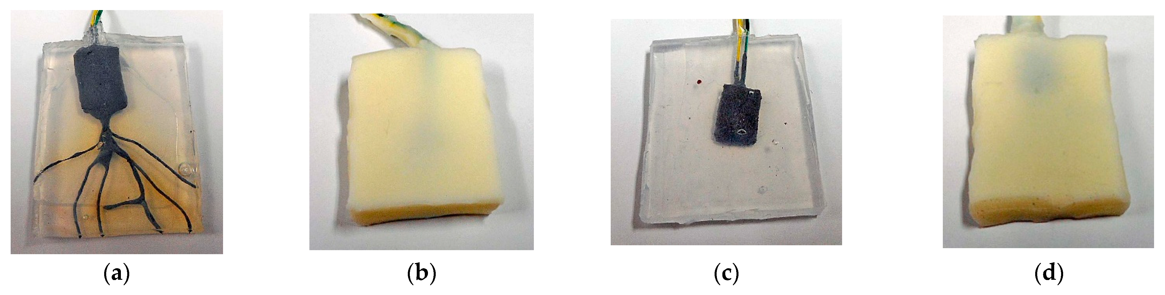
2. Materials
- (a)
- Solidification
- (b)
- Creation of built-in voltage and current
- (c)
- Production of porous rubber, and infiltration with a liquid
- (d)
- Adhesion of a rubber to metal
3. Experimental Procedure
4. Results and Discussion
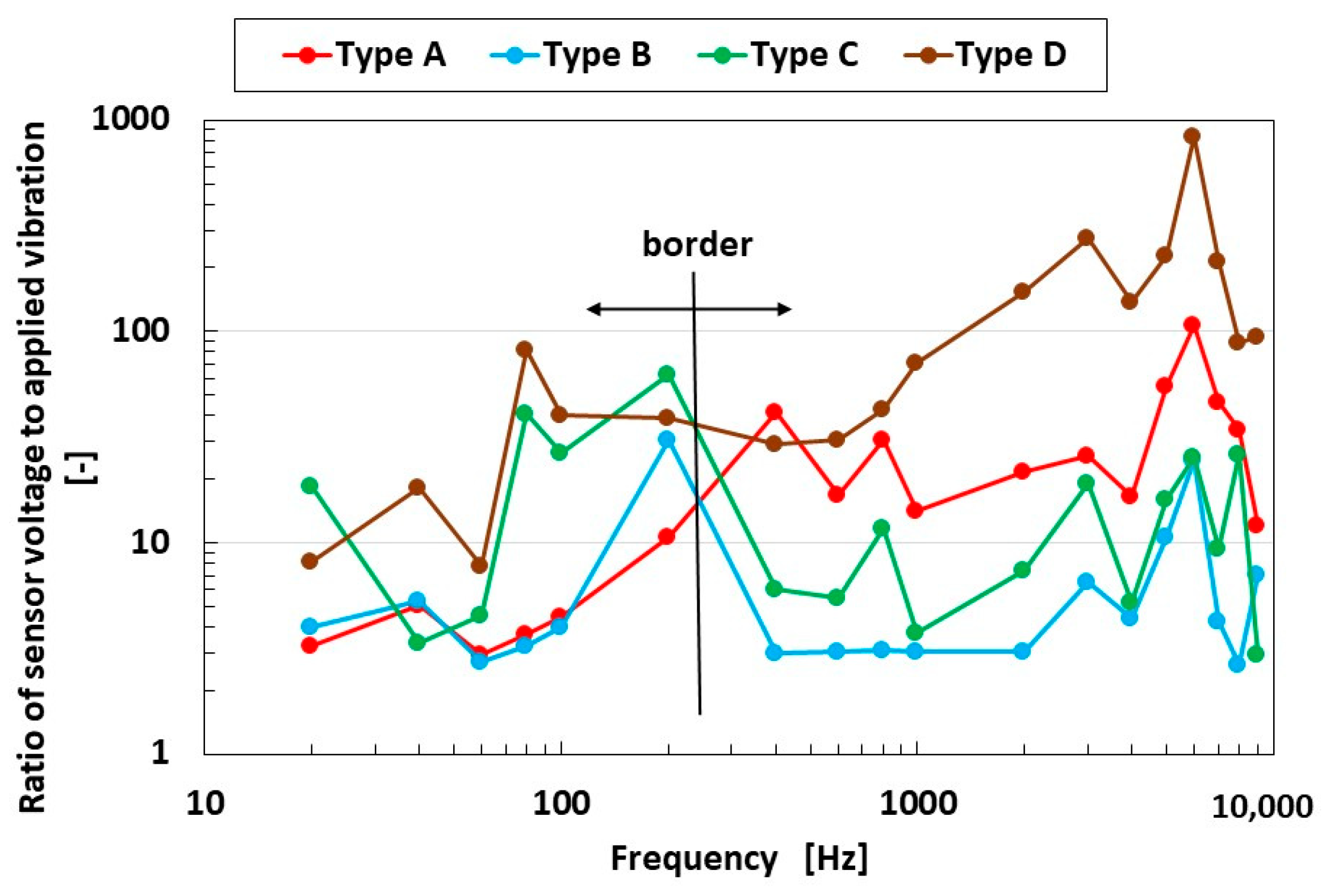
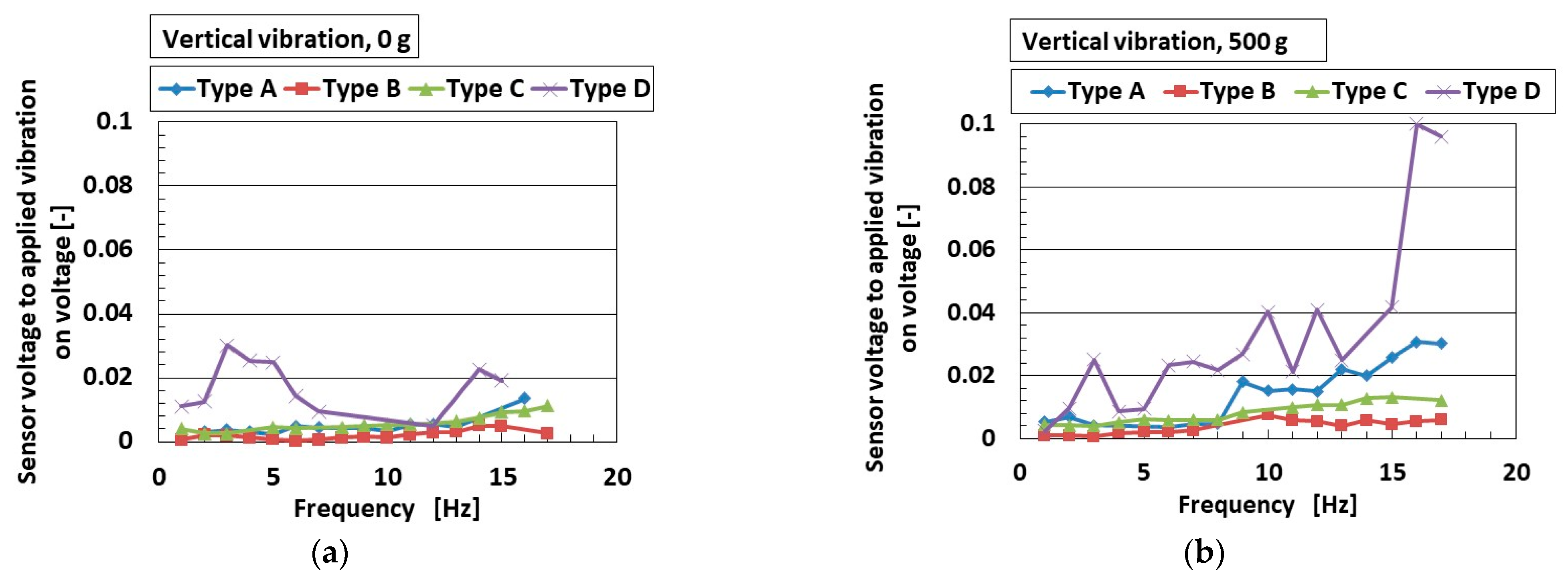
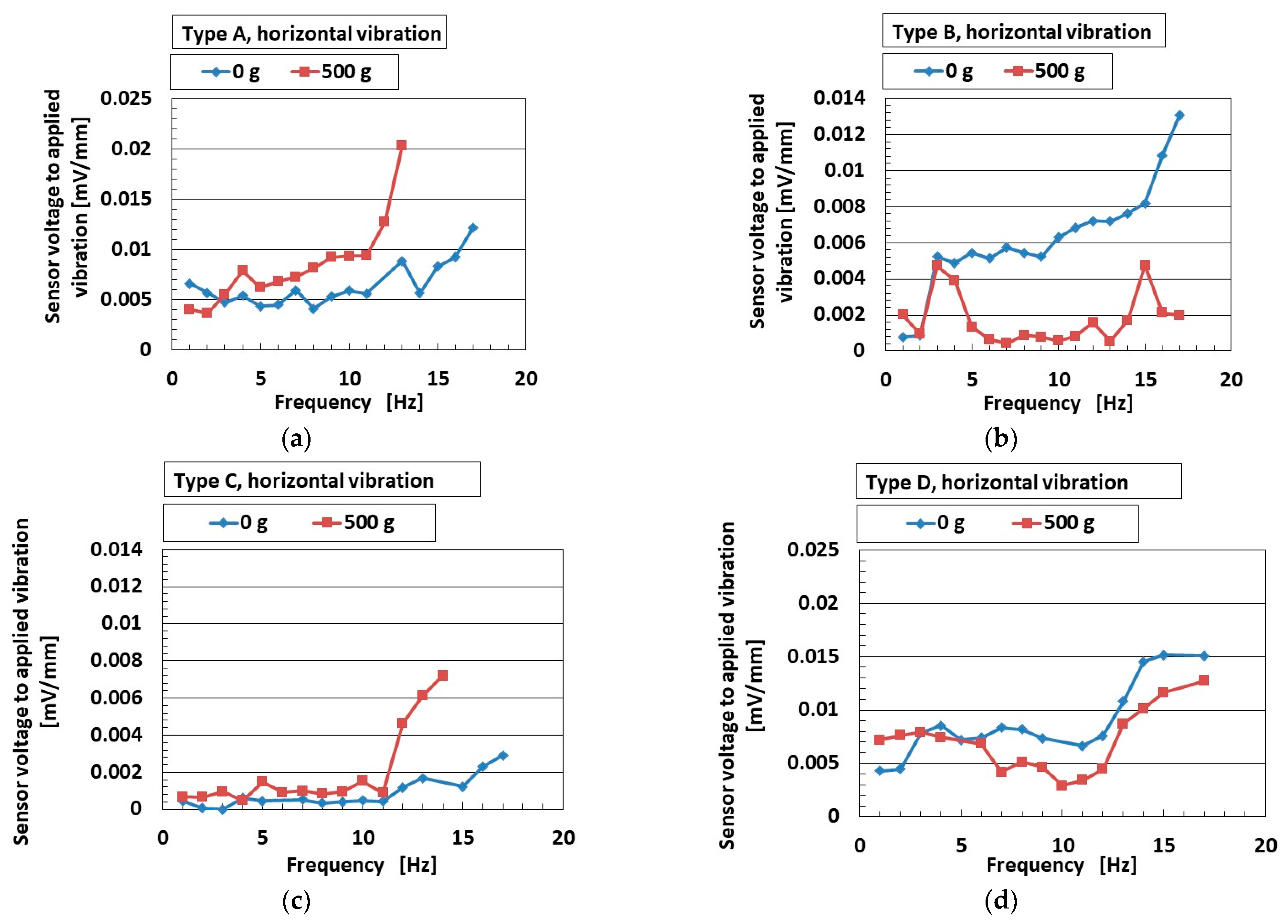
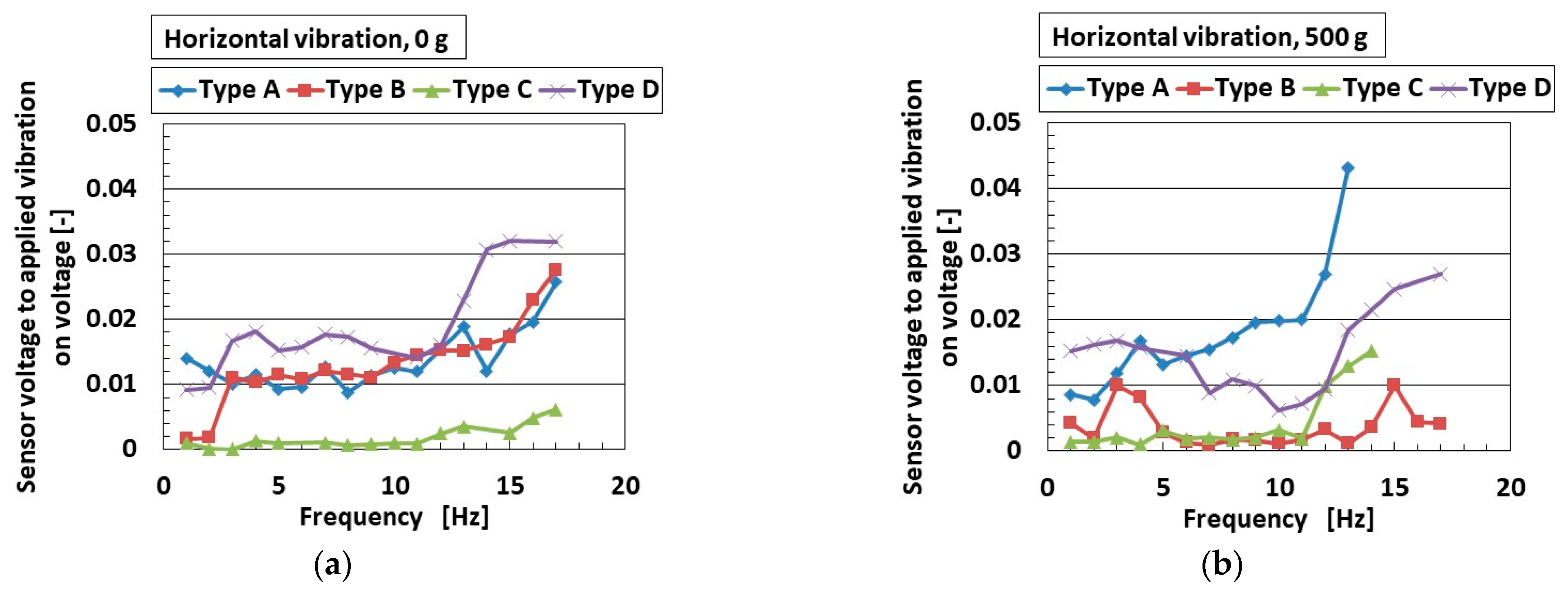
4.1. High-Frequency Response
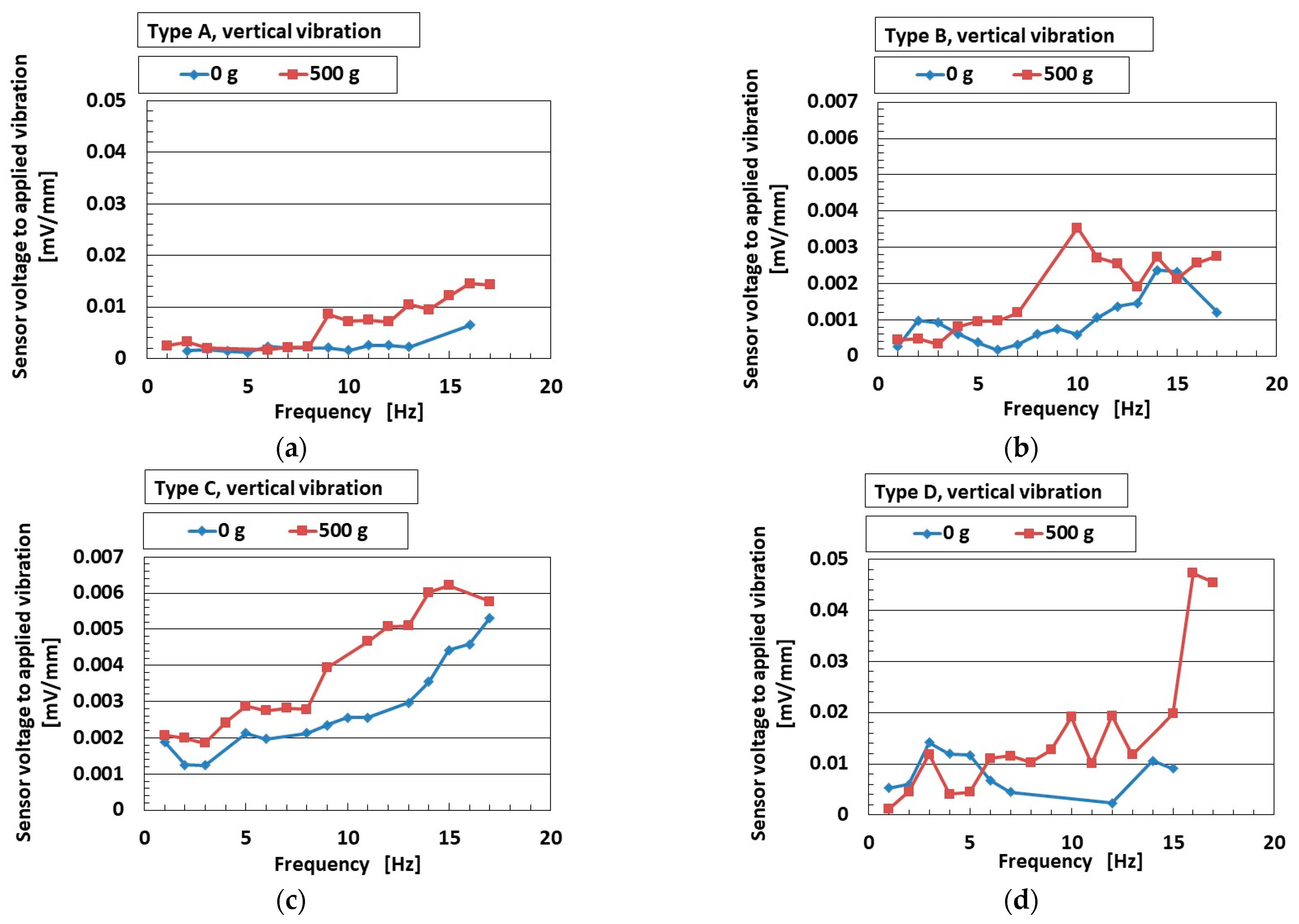
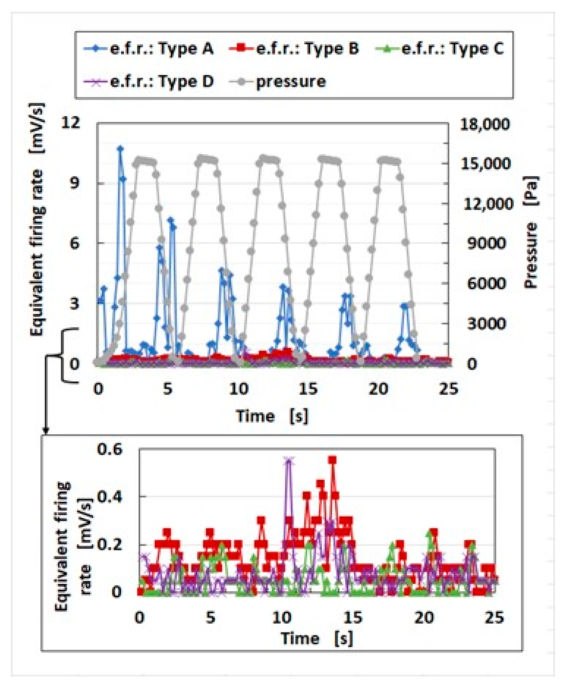
4.2. Low-Frequency Response
4.3. Multi-Faceted Consideration
4.3.1. Stimuli to Vibration
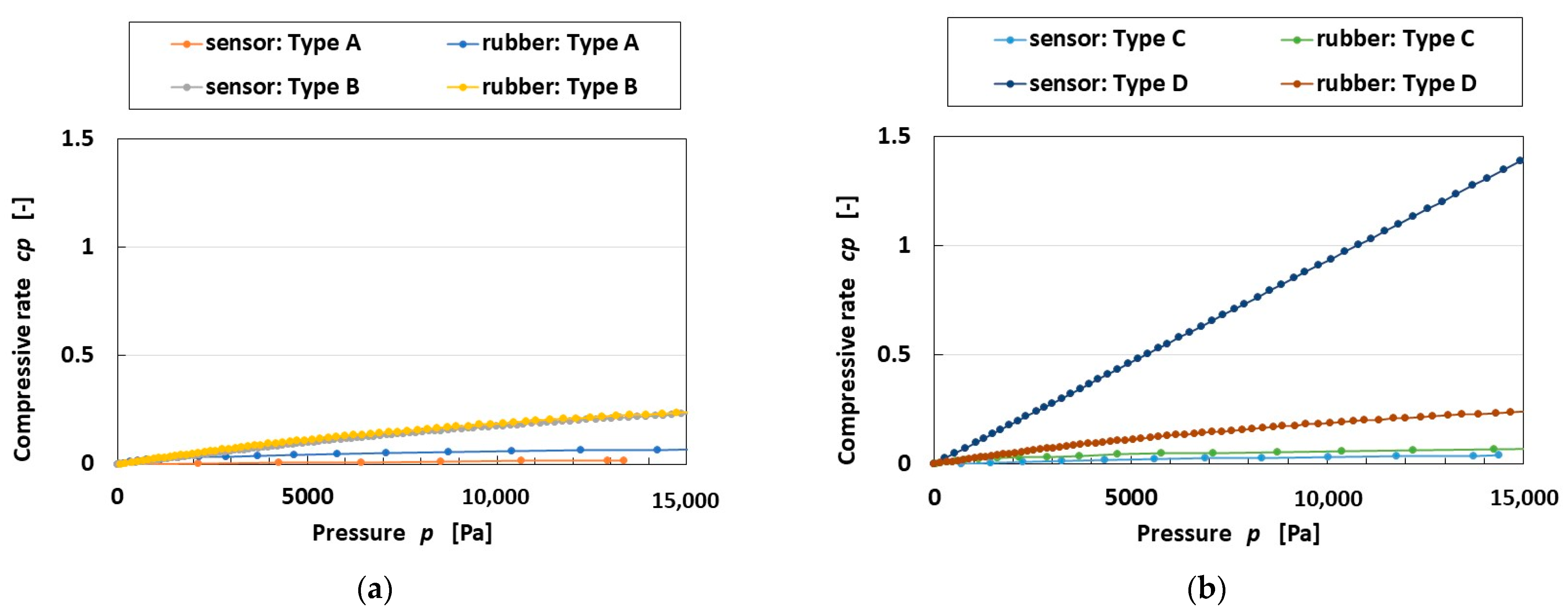
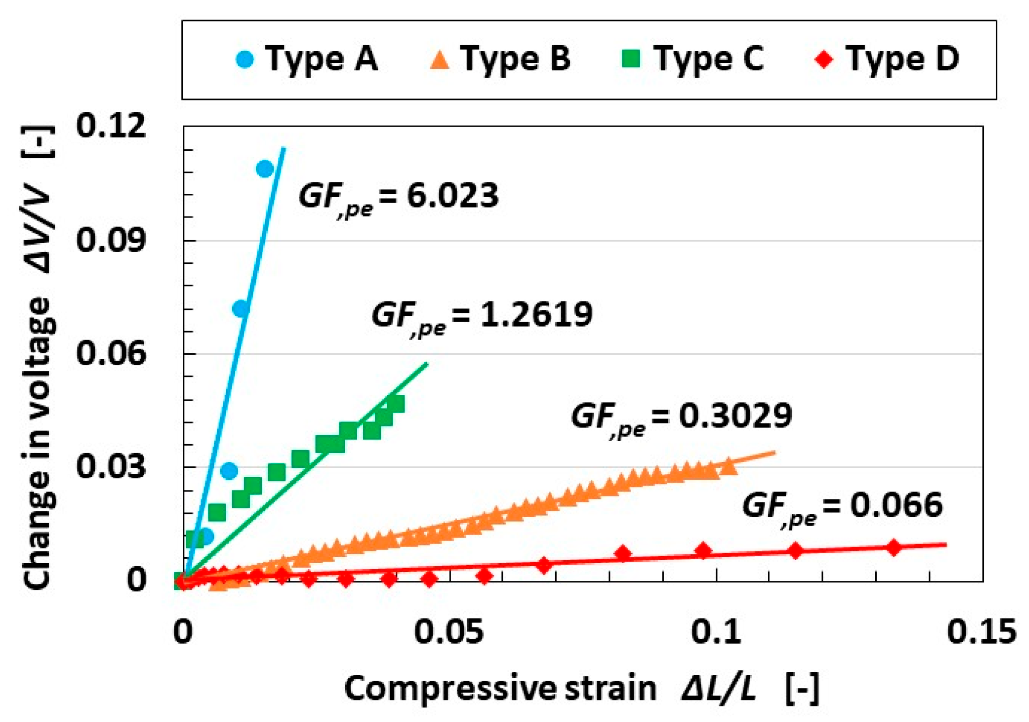
4.3.2. Gauge Factor for Piezo-Electricity
5. Conclusions
Funding
Institutional Review Board Statement
Informed Consent Statement
Data Availability Statement
Acknowledgments
Conflicts of Interest
References
- Urhal, P.; Weightman, A.; Diver, C.; Bartolo, P. Robot assisted additive manufacturing: A review. Robot. Comput. Integrat. Manuf. 2019, 59, 335–345. [Google Scholar] [CrossRef]
- Yang, G.Z.; Bellingham, J.; Dupont, P.E.; Fischer, P.; Floridi, L.; Full, R.; Jacobstein, N.; Kumar, V.; McNutt, M.; Merrifield, R.; et al. The grand challenges of science robotics. Sci. Robot. 2018, 3, eaar7650. [Google Scholar] [CrossRef] [PubMed]
- Luan, H.; Zhang, Y. Programmable stimulation and actuation in flexible and stretchable electronics. Adv. Intell. Syst. 2021, 3, 2000228. [Google Scholar] [CrossRef]
- Ji, X.; Zhao, X.; Tan, M.C.; Zhao, R. Artificial perception built on memristive system: Visual, auditory, and tactile sensations. Adv. Intell. Syst. 2020, 2, 1900118. [Google Scholar] [CrossRef]
- Svechtarova, M.I.; Buzzacchera, I.; Tobes, B.J.; Lauko, J.; Anton, N.; Wilson, C.J. Sensor devices inspired by the five sensors: A review. Electroanalysis 2016, 28, 1201–1241. [Google Scholar] [CrossRef]
- Chadha, U.; Bhardwaj, P.; Agarwal, R.; Rawat, P.; Agarwal, R.; Gupta, I.; Panjwani, M.; Singh, S.; Ahuja, C.; Selvaraj, S.K.; et al. Recent progress and growth in biosensors technology: A critical review. J. Ind. Eng. Chem. 2022, 109, 21–51. [Google Scholar] [CrossRef]
- Patel, S.; Rao, Z.; Yang, M.; Yu, C. Wearable haptic feedback interfaces for augmenting human touch. Adv. Funct. Mater. 2025, 2417906. [Google Scholar] [CrossRef]
- Sun, Y.; He, W.; Jiang, C.; Li, J.; Li, J.; Liu, M. Wearable biodevices based on two-dimensional materials: From flexible sensors to smart integrated systems. Nano-Micro Lett. 2025, 17, 109. [Google Scholar] [CrossRef]
- Ullah, H.; Wahab, M.A.; Will, G.; Karim, M.R.; Pan, T.; Gao, M.; Lai, D.; Lin, Y.; Miraz, M.H. Recent advances in stretchable and wearable capacitive electrophysiological sensors for long-term health monitoring. Biosensors 2022, 12, 630. [Google Scholar] [CrossRef]
- Cho, K.W.; Sunwoo, S.H.; Hong, Y.J.; Koo, J.H.; Kim, J.H.; Baik, S.; Hyeon, T.; Kim, D.H. Soft bioelectronics based on nanomaterials. Chem. Rev. 2022, 122, 5068–5143. [Google Scholar] [CrossRef]
- Andreozzi, E.; Sabbadini, R.; Centracchio, J.; Bifulco, P.; Irace, A.; Breglio, G.; Riccio, M. Multimodal finger pulse wave sensing: Comparison of forcecardiography and photoplethysmography sensors. Sensors 2022, 22, 7566. [Google Scholar] [CrossRef]
- Yang, T.; Jiang, X.; Huang, Y.; Tian, Q.; Zhang, L.; Dai, Z.; Zhu, H. Mechanical sensors based on two-dimensional materials: Sensing mechanisms, structural designs and wearable applications. iScience 2022, 25, 103728. [Google Scholar] [CrossRef]
- Babatain, W.; Bhattacharjee, S.; Hussain, A.M.; Hussain, M.M. Acceleration sensors: Sensing mechanisms, emerging fabrication strategies, materials, and applications. Appl. Electron. Mater. 2021, 3, 504–531. [Google Scholar] [CrossRef]
- Zhang, W.; Gu, G.; Ren, H.; Zhang, Z.; Zhang, Z.; Qin, H.; Zheng, M.; Du, Z.; Cheng, G. A real-time self-powered wireless pressure sensing system based on capacitive triboelectric pressure sensor. Nano Energy 2025, 136, 110729. [Google Scholar] [CrossRef]
- Guo, Y.; Wang, Y.; Tong, Q.; Shan, B.; He, L.; Zhang, Y.; Wang, D. Active electronic skin: An interface towards ambient haptic feedback on physical surfaces. Npj Flex. Electron. 2024, 8, 25. [Google Scholar] [CrossRef]
- Tanaka, M.; Leveque, J.L.; Tagami, H.; Kikuchi, K.; Chonan, S. The “haptic finger”—A new device for monitoring skin condition. Ski. Res. Technol. 2003, 9, 131–136. [Google Scholar] [CrossRef]
- Hua, Q.; Sun, J.; Liu, H.; Bao, R.; Yu, R.; Zhai, J.; Pan, C.; Wang, Z.L. Skin-inspired highly stretchable and conformable matrix networks for multifunctional sensing. Nat. Commun. 2018, 9, 244. [Google Scholar] [CrossRef]
- Lee, H.S.; Chung, J.; Hwang, G.T.; Jeong, C.K.; Jung, Y.; Kwak, J.H.; Kang, H.; Byun, M.; Kim, W.D.; Hur, S.; et al. Flexible inorganic piezoelectric acoustic nanosensors for biomimetic artificial hair cells. Adv. Funct. Mater. 2014, 24, 6914–6921. [Google Scholar] [CrossRef]
- Inaoka, T.; Shintaku, H.; Nakagawa, T.; Kawano, S.; Ogita, H.; Sakamoto, T.; Hamanishi, S.; Wada, H.; Ito, J. Piezoelectric materials mimic the function of the cochlear sensory epithelium. Proc. Natl. Acad. Sci. USA 2011, 108, 18390–18395. [Google Scholar] [CrossRef]
- Raoufi, M.A.; Moshizi, S.A.; Razmjou, A.; Wu, S.; Ebrahimi Warkiani, M.E.; Asadnia, M. Development of a biomimetic semicircular canal with MEMS sensors to restore balance. IEEE Sens. J. 2019, 19, 11675–11686. [Google Scholar] [CrossRef]
- Moshizi, S.; Azadi, S.; Belford, A.; Razmjou, A.; Wu, S.; Han, Z.J.; Asadnia, M. Development of an ultra-sensitive and flexible piezoresistive flow sensor using vertical graphene nanosheets. Nano-Micro Lett. 2020, 12, 109. [Google Scholar] [CrossRef]
- Zhao, T.; Wang, Q.; Du, A. Self-powered flexible sour sensor for detecting ascorbic acid concentration based on triboelectrification/enzymatic-reaction coupling effect. Sensors 2021, 21, 373. [Google Scholar] [CrossRef]
- Zhang, N.; Wei, X.; Fan, Y.; Zhou, X.; Liu, Y. Recent advances in development of biosensors for taste-related analyses. TrAC Trends Anal. Chem. 2020, 129, 115925. [Google Scholar] [CrossRef]
- Baldwin, E.A.; Bai, J.; Plotto, A.; Dea, S. Electronic noses and tongues: Applications for the food and pharmaceutical industries. Sensors 2011, 11, 4744–4766. [Google Scholar] [CrossRef]
- Kim, C.; Lee, K.K.; Kang, M.S.; Shin, D.M.; Oh, J.W.; Lee, C.S.; Han, D.W. Artificial olfactory sensor technology that mimics the olfactory mechanism: A comprehensive review. Biomater. Res. 2022, 26, 40. [Google Scholar] [CrossRef]
- Cheng, L.; Meng, Q.H.; Lilienthal, A.J.; Qi, P.F. Development of compact electronic noses: A review. Meas. Sci. Technol. 2021, 32, 062002. [Google Scholar] [CrossRef]
- Covington, J.A.; Marco, S.; Persaud, K.C.; Schiffman, A.S.; Nagle, H.T. Artificial olfaction in the 21st century. IEEE Sens. J. 2021, 21, 12969–12990. [Google Scholar] [CrossRef]
- Chen, S.; Yang, Z.; Huang, Q.; Li, K.; Ge, S. Vibrotactile sensation: A systematic review of the artificial Pacinian corpuscle. J. Bionic Eng. 2023, 20, 1401–1416. [Google Scholar] [CrossRef]
- Na, H.M.; Chu, K.Y.; Seo, S.; Han, C.S. Artificial Ruffini sensor using CNT/ecoflex composite for human movement monitoring. Sens. Actuators A Phys. 2024, 378, 115843. [Google Scholar] [CrossRef]
- Zheng, Y.; Li, Y.; Dai, K.; Wang, Y.; Zheng, G.; Liu, C.; Shen, C. A highly stretchable and stable strain sensor based on hybrid carbon nanofillers/polydimethylsiloxane conductive composites for large human motions monitoring. Compos. Sci. Technol. 2018, 156, 276–286. [Google Scholar] [CrossRef]
- Sengupta, D.; Pei, Y.; Kottapalli, A.G.P. Ultralightweight and 3D squeezable graphene-polydimethylsiloxane composite foams as piezoresistive sensors. ACS Appl. Mater. Interfaces 2019, 11, 35201–35211. [Google Scholar] [CrossRef]
- Amjadi, M.; Yoon, Y.J.; Park, I. Ultra-stretchable and skin-mountable strain sensors using carbon nanotubes–Ecoflex nanocomposites. Nanotechnology 2015, 26, 375501. [Google Scholar] [CrossRef]
- Seong, M.; Hwang, I.; Lee, J.; Jeong, H.E. A pressure-insensitive self-attachable flexible strain sensor with bioinspired adhesive and active CNT layers. Sensors 2020, 20, 6965. [Google Scholar] [CrossRef]
- Wang, D.; Zhang, J.; Ma, G.; Fang, Y.; Liu, L.; Wang, J.; Ren, L. A selective-response bioinspired strain sensor using viscoelastic material as middle layer. ACS Nano 2021, 15, 19629–19639. [Google Scholar] [CrossRef]
- Zhang, Z.; Xie, C.; Zhang, J.; Chan, M.; Zhang, M. Tunable stretchable strain sensors enabled by patterned Ecoflex-vertical aligned carbon nanotube arrays and pre- stretching transfer. Carbon 2022, 197, 218–225. [Google Scholar] [CrossRef]
- Li, G.; Xue, Y.; Peng, H.; Qin, W.; Zhou, B.; Zhao, X.; Guo, R. Wide strain range and high sensitivity sandwich structure CNTs/AgNWs/CNTs/TPU strain sensors for human motion detection. Sens. Actuators A Phys. 2024, 366, 114998. [Google Scholar] [CrossRef]
- Xia, J.; He, L.; Lu, Z.; Song, J.; Wang, Q.; Liu, L.; Tian, Y. High performance strain sensor based on carbon black/graphene/ecoflex for human health monitoring and vibration signal detection. ACS Appl. Nano Mater. 2023, 6, 19279–19289. [Google Scholar] [CrossRef]
- Zheng, C.; Gao, D.G.; Lyu, B.; Zhang, C.G.; Li, H.; Zhou, Y.Y.; Li, N.; Ma, J.Z. A triboelectric sensor with highly sensitive and durable: Dual regulation strategy based on surface morphology and functional groups on negative/positive tribolayers. Chem. Eng. J. 2023, 477, 147071. [Google Scholar] [CrossRef]
- Peng, F.; Ren, K.L.; Chen, R.R.; Liu, D.; Ning, C.; Zheng, G.Q.; Dai, K.; Liu, C.T.; Shen, C.Y. Vertically aligned polymer microfibril array for self-powered sensing. Nano Energy 2024, 124, 109440. [Google Scholar] [CrossRef]
- Chiu, Y.S.; Rinawati, M.; Chang, Y.H.; Aulia, S.; Chang, C.C.; Chang, L.Y.; Hung, W.S.; Mizuguchi, H.; Haw, S.C.; Yeh, M.H. Enhancing self-induced polarization of PVDF-based triboelectric film by P-doped g-C3N4 for ultrasensitive triboelectric pressure sensors. Nano Energy 2024, 131, 110207. [Google Scholar] [CrossRef]
- Xie, X.K.; Wang, Q.N.; Zhao, C.; Sun, Q.L.; Gu, H.C.; Li, J.Y.; Tu, X.; Nie, B.Q.; Sun, X.H.; Liu, Y.N.; et al. Neuromorphic computing-assisted triboelectric capacitive-coupled tactile sensor array for wireless mixed reality interaction. ACS Nano 2024, 18, 17041–17052. [Google Scholar] [CrossRef] [PubMed]
- Wang, J.J.; Cui, P.; Zhang, J.J.; Ge, Y.; Liu, X.L.; Xuan, N.N.; Gu, G.Q.; Cheng, G.; Du, Z.L. Experimental study on fatigue degradation of piezoelectric energy harvesters under equivalent traffic load conditions. Nano Energy 2021, 89, 106320. [Google Scholar] [CrossRef]
- Yi, P.; Fu, X.P.; Liu, Y.; Zhang, X.Y.; Zhang, C.; Li, X.W. Triboelectric active pressure sensor with ultrabroad linearity range by femtosecond laser shaping based on electrons dynamics control. Nano Energy 2023, 113, 108592. [Google Scholar] [CrossRef]
- Sun, H.; Sun, X.Y.; Buranabunwong, C.; Li, X.X.; Zhang, S.W.; Chen, Y.; Li, M. Flexible capacitive sensor based on Miura-ori structure. Chem. Eng. J. 2023, 468, 143514. [Google Scholar] [CrossRef]
- Tagawa, Y.; Lee, S.; Someya, T.; Yokota, T. A capacitive pressure sensor with linearity and high sensitivity over a wide pressure range using thermoplastic microspheres. Adv. Electron. Mater. 2023, 9, 2201304. [Google Scholar] [CrossRef]
- Han, R.H.; Liu, Y.; Mo, Y.P.; Xu, H.C.; Yang, Z.W.; Bao, R.R.; Pan, C.F. High anti-jamming flexible capacitive pressure sensors based on core–shell structured AgNWs@TiO2. Adv. Funct. Mater. 2023, 33, 2305531. [Google Scholar] [CrossRef]
- Chen, L.T.; Zheng, B.Y.; Ye, J.H.; Wu, H.B. Cone-shaped electrodes for capacitive tactile sensors with high sensitivity and broad linearity range. Adv. Mater. Technol. 2023, 8, 2300901. [Google Scholar] [CrossRef]
- Lei, M.; Ji, B.; Ding, S.; Liu, R.L.; Zhou, B.P. Template-free formation of hybrid dielectric for flexible capacitive sensors with wide-pressure-range linear detection. Adv. Mater. Technol. 2023, 8, 2301077. [Google Scholar] [CrossRef]
- Yu, H.B.; Guo, H.J.; Wang, J.G.; Zhao, T.M.; Zou, W.H.; Zhou, P.L.; Xu, Z.; Zhang, Y.Z.; Zheng, J.C.; Zhong, Y.; et al. Skin-inspired capacitive flexible tactile sensor with an asymmetric structure for detecting directional shear forces. Adv. Sci. 2024, 11, 2305883. [Google Scholar] [CrossRef]
- Chung, D.D.L. A critical review of piezoresistivity and its application in electrical-resistance-based strain sensing. J. Mater. Sci. 2020, 55, 15367–15396. [Google Scholar] [CrossRef]
- Park, M.; Bok, B.G.; Ahn, J.H.; Kim, M.S. Recent advances in tactile sensing technology. Micromachines 2018, 9, 321. [Google Scholar] [CrossRef] [PubMed]
- Wang, L.; Chen, Y.; Lin, L.; Wang, H.; Huang, X.; Xue, H.; Gao, J. Highly stretchable, anti-corrosive and wearable strain sensors based on the PDMS/CNTs decorated elastomer nanofiber composite. Chem. Eng. J. 2019, 362, 89–98. [Google Scholar] [CrossRef]
- Sun, H.; Bu, Y.; Liu, H.; Wang, J.; Yang, W.; Li, Q.; Guo, Z.; Liu, C.; Shen, C. Superhydrophobic conductive rubber band with synergistic dual conductive layer for wide-range sensitive strain sensor. Sci. Bull. 2022, 67, 1669–1678. [Google Scholar] [CrossRef] [PubMed]


| Ingredients | HF Rubber 1 | HF Rubber 2 | HF Rubber 3 | HF Rubber 4 |
|---|---|---|---|---|
| water | 3 g | 3 g | 1 g | 1 g |
| sodium tungstate (VI) dehydrate (Na2WO4 2H2O, Fujifilm Wako Chemical Co., Ltd., Osaka, Japan) | 0.5 g | 0.5 g | - | 0.5 g |
| TiO2 | 0.5 g | 0.5 g | 0.5 g | 0.5 g |
| HF | 1 g | 1 g | 1 g | 1 g |
| NR-latex (Ulacol; Rejitex Co., Ltd., Atsugi, Japan) | 3 g | 3 g | 3 g | 3 g |
| CR-latex (671A; Showa Denko Co., Ltd., Tokyo, Japan) | 3 g | 3 g | 3 g | 3 g |
| carbonyl Ni powder (BASF Japan Co., Ltd., Tokyo, Japan) | 3 g | 3 g | 3 g | 3 g |
| Type of Sensor and Rubber | Quantitative Comparison | Approximate Curve | Coefficient of Determination |
|---|---|---|---|
| sensor: Type A | low | cp = −2 × 10⁻¹¹ p2 + 2 × 10⁻⁶ p | 0.9892 |
| rubber: Type A | low | cp = −6 × 10⁻¹¹ p2 + 5 × 10⁻⁶ p | 0.9477 |
| sensor: Type B | middle | cp = −4 × 10⁻¹⁰ p2 + 2 × 10⁻⁵ p | 0.9997 |
| rubber: Type B | middle | cp = −3 × 10⁻¹⁰ p2 + 2 × 10⁻⁵ p | 0.9934 |
| sensor: Type C | low | cp = −1 × 10⁻¹⁰ p2 + 5 × 10⁻⁶ p | 0.9958 |
| rubber: Type C | low | cp = −6 × 10⁻¹¹ p2 + 5 × 10⁻⁶ p | 0.9477 |
| sensor: Type D | high | cp = −3 × 10⁻²³ p2 + 9 × 10⁻⁵ p | 1 |
| rubber: Type D | middle | cp = −3 × 10⁻¹⁰ p2 + 2 × 10⁻⁵ p | 0.9932 |
| Kinds of Sensors with Material | Optimal Vibrational Performance [Hz] | Duration [cycles] |
|---|---|---|
| S.S.S. with carbon nanotube (CNT), carbon black (CB), polyurethane, and polydimethylsiloxane (PDMS) [30] | 0.083 | 2500 |
| S.S.S. with graphene and PDMS [31] | 70 | 36,000 |
| S.S.S. with CNT and biodegradable plastic (Ecoflex) [32] | 0.067 | 2000 |
| S.S.S. with multiwalled CNT (MWCNT) and PDMS [33] | 0.067 | 1000 |
| S.S.S. with PVA, PDMS, and Ag nano-particles (AgNP) [34] | 100 | 2000 |
| S.S.S. with vertically aligned carbon nanotube (VACNT) and Ecoflex [35] | 4 | 10,000 |
| S.S.S. with CNT, Ag nano-wire (AgNW), and thermoplastic polyurethane pellets (TPUs) [36] | 2 | 2500 |
| S.S.S. with CB, graphene, and Ecoflex [37] | 1 | 4000 |
| S.S.S. with MWCNT and Ecoflex [29] | 40 | 12,000 |
| present sensor in this study (Types A–D) | 200–10,000 | 10,000 |
| Kinds of Sensors with Material | Sensitivity [mV/Pa] | Response Time [ms] |
|---|---|---|
| triboelectric sensor [38] | 1.06 | |
| triboelectric nanogenerator (TENG) [39] | 3.4 | |
| polyvinylidene difluoride (PVDF)-based triboelectric film [40] | 1.48 | |
| triboelectric capacitive-coupled tactile sensor [41] | 7.88 | |
| piezoelectric energy harvesters (PEHs) [42] | 0.29 | |
| triboelectric active pressure sensor [43] | 12.8 | |
| flexible capacitive sensor based on Miura-ori structure [44] | 100 | |
| flexible pressure sensor with thermoplastic microspheres (TPM) [45] | 98 | |
| high anti-jamming capacitive flexible pressure sensor with PVD, AgNWs, and TiO2 film [46] | 166.9 | |
| capacitive tactile sensors with cone-shaped electrodes [47] | 100 | |
| flexible capacitive sensors with template-free formation of hybrid dielectric [48] | 97 | |
| skin-inspired capacitive flexible tactile sensor [49] | 60 | |
| present sensor in this study (Type A at low frequency) | 4.4 × 10⁻⁴ | 100 |
| present sensor in this study (Type B at low frequency) | 1.8 × 10⁻⁴ | 5000 |
| present sensor in this study (Type C at low frequency) | 9.5 × 10⁻⁶ | 100 |
| present sensor in this study (Type D at low frequency) | 5.1 × 10⁻⁵ | 600 |
| present sensor in this study (Types A–D at high frequency) | 0.1 |
Disclaimer/Publisher’s Note: The statements, opinions and data contained in all publications are solely those of the individual author(s) and contributor(s) and not of MDPI and/or the editor(s). MDPI and/or the editor(s) disclaim responsibility for any injury to people or property resulting from any ideas, methods, instructions or products referred to in the content. |
© 2025 by the author. Licensee MDPI, Basel, Switzerland. This article is an open access article distributed under the terms and conditions of the Creative Commons Attribution (CC BY) license (https://creativecommons.org/licenses/by/4.0/).
Share and Cite
Shimada, K. Cutting-Edge Vibration Sensor Morphologically Configured by Mimicking a Tactile Cutaneous Receptor Using Magnetic-Responsive Hybrid Fluid (HF). Sensors 2025, 25, 3366. https://doi.org/10.3390/s25113366
Shimada K. Cutting-Edge Vibration Sensor Morphologically Configured by Mimicking a Tactile Cutaneous Receptor Using Magnetic-Responsive Hybrid Fluid (HF). Sensors. 2025; 25(11):3366. https://doi.org/10.3390/s25113366
Chicago/Turabian StyleShimada, Kunio. 2025. "Cutting-Edge Vibration Sensor Morphologically Configured by Mimicking a Tactile Cutaneous Receptor Using Magnetic-Responsive Hybrid Fluid (HF)" Sensors 25, no. 11: 3366. https://doi.org/10.3390/s25113366
APA StyleShimada, K. (2025). Cutting-Edge Vibration Sensor Morphologically Configured by Mimicking a Tactile Cutaneous Receptor Using Magnetic-Responsive Hybrid Fluid (HF). Sensors, 25(11), 3366. https://doi.org/10.3390/s25113366