
Moving Microgrid Hierarchical Control to an SDN-Based Kubernetes Cluster: A Framework for Reliable and Flexible Energy Distribution

 ,
,  , ,
, ,  and
and 
Abstract
1. Introduction
- Reliability [32]: Bare-metal Kubernetes provides a highly reliable infrastructure for microgrids by distributing the workloads across multiple nodes and ensuring the high availability of resources.
- Computational cost [33]: Low costs because virtualization software is no longer necessary. Cluster automation and microservices deployment are straightforward because there is no hypervisor.
- Low latency [34]: Microgrids require low latency and high-speed communication between the devices to ensure safe and efficient operations. Bare-metal Kubernetes provides low-latency network connectivity and efficient data communication.
- Scalability [36]: Network configuration is more straightforward on the bare-metal cluster and troubleshooting. Microgrids require the ability to scale up or down depending on the demand. Bare-metal Kubernetes provides automatic scaling and load balancing, which can help ensure optimal performance under varying load conditions.
- A new architecture, based on microservices, as a solution to the centralized SDN controller problem regarding load balancing, scalability, and low latency. The proposed methods improve the global resilience of the system and allow the integration of SDN controllers as pod services in distributed Kubernetes platforms. The proposed approach allows the deployment of bare-metal Kubernetes cluster parameters and can be applied to multiple configurations of AC/DC microgrids.
- A new SDN communication architecture has been developed for hardware-in-the-loop platforms connected to Raspberry pi, serving as both a Kubernetes worker and an OpenFlow communication device. Furthermore, this paper analyzes the most significant drawbacks of the SDN control plane in networked microgrids.
- Provides a proof of concept to apply for segregating and orchestrating services in bare-metal Kubernetes cluster. The proposed method decreases the data flow traffic through the SDN infrastructure, setting the most appropriate route between the DGs. The distributed communication system is capable of managing real-time energy data.
2. Main Disadvantage of an SDN Controller
2.1. Centralized Controller
2.2. Monolithic Controller
2.3. Variability in Programming Interfaces
2.4. Dependencies between Applications and Controllers
2.5. Lack of Reliability and Scalability of SDN Controller
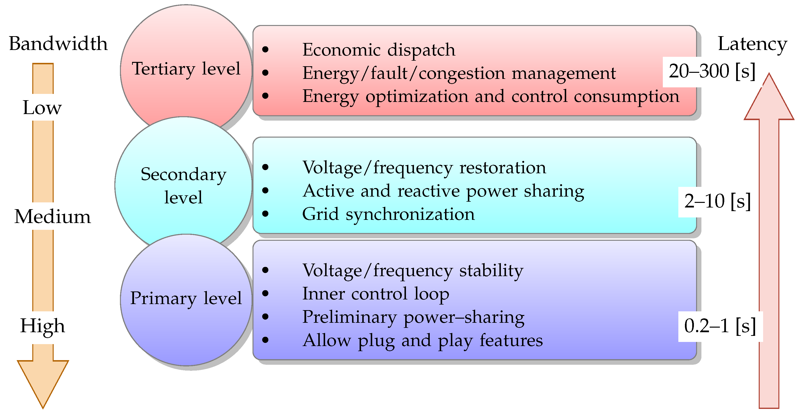
3. Hierarchical Control Approach
4. Disaggregating Functionalities and Migrating SDN as Microservices
Components and Interfaces as Microservices
5. Implementation of μONOS SDN Controller
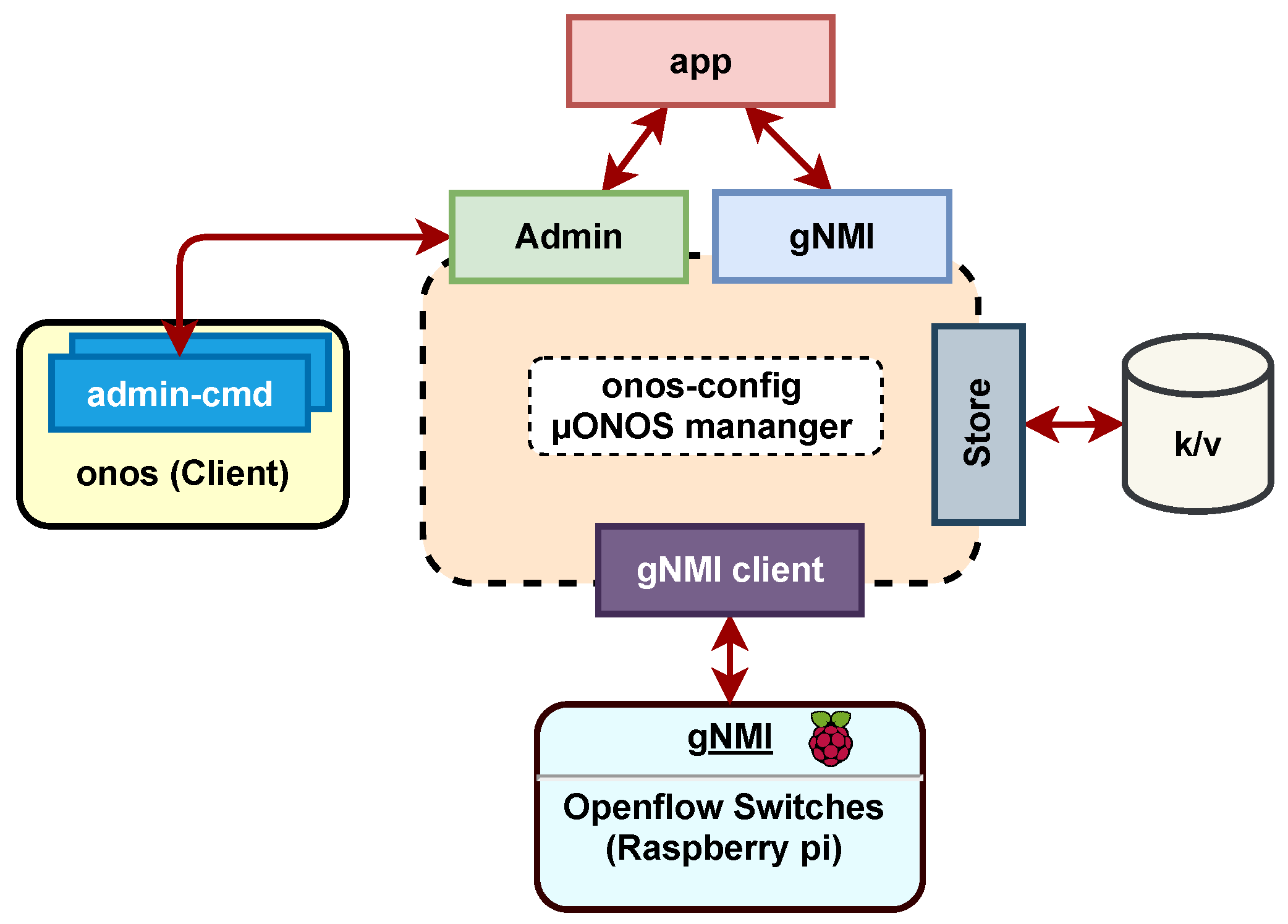
5.1. Functionalities of onos-config Module
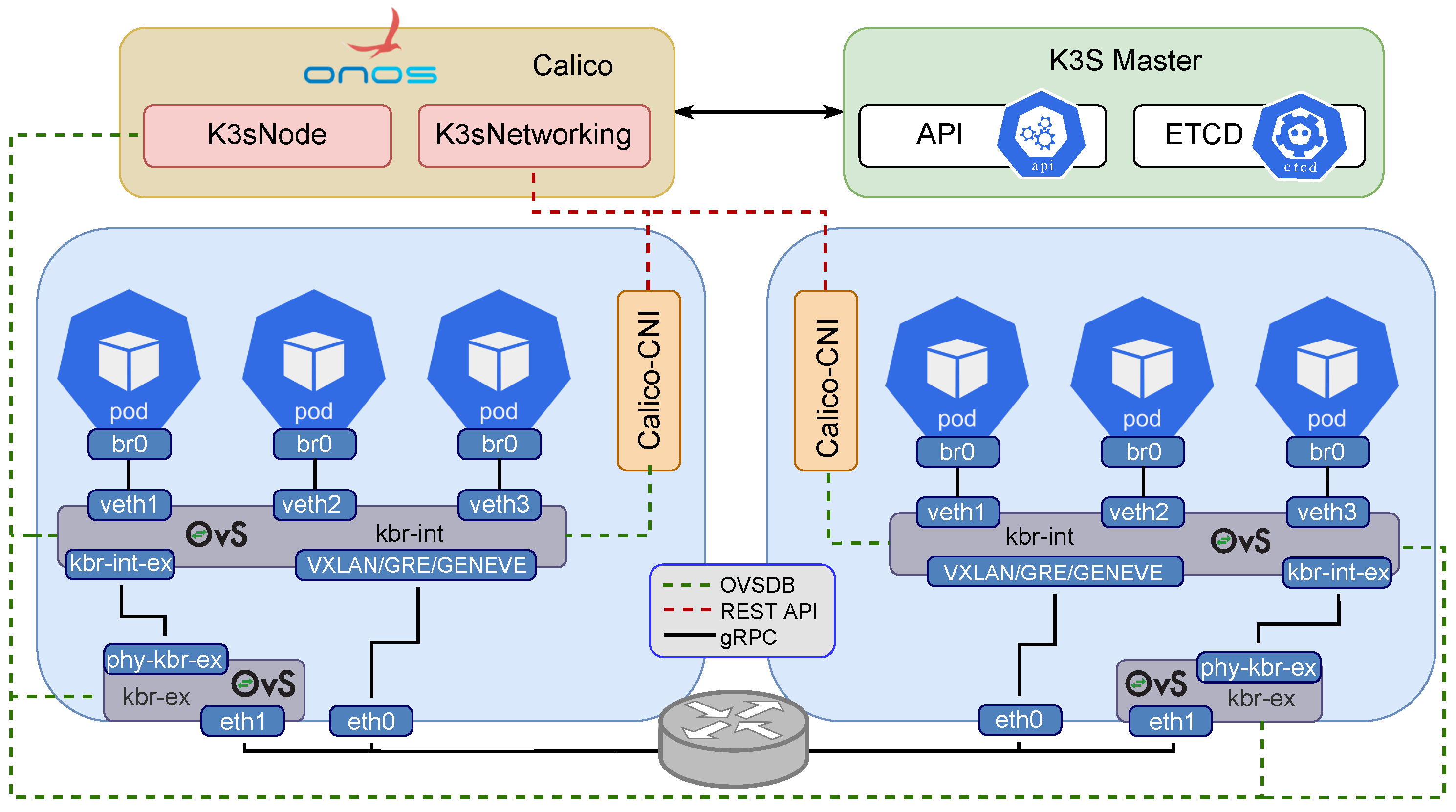
5.2. Network Interface Cluster Implementation
5.3. Create the Kubernetes Cluster on Raspberry
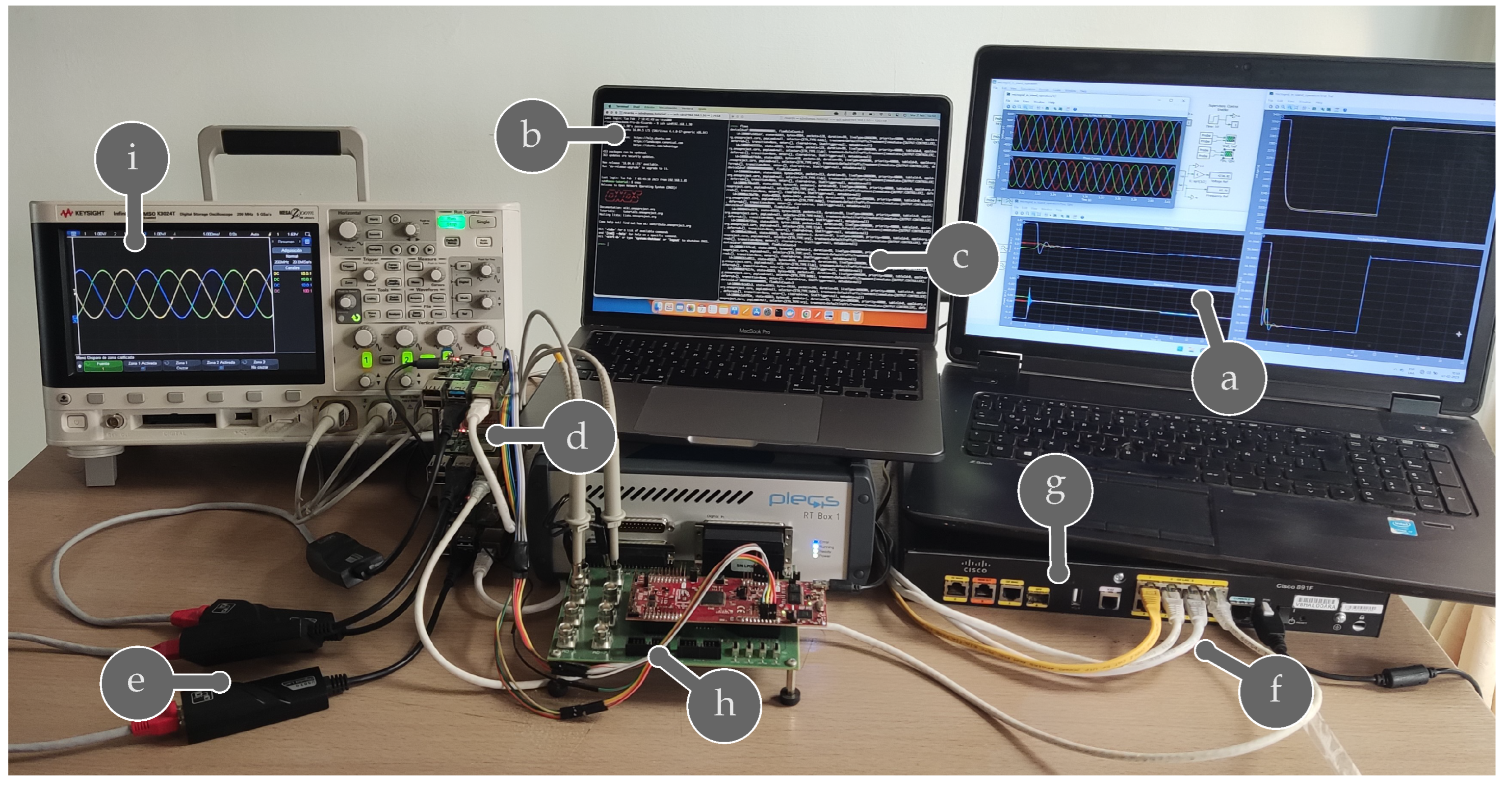
5.4. Connection to PLECS RT Box
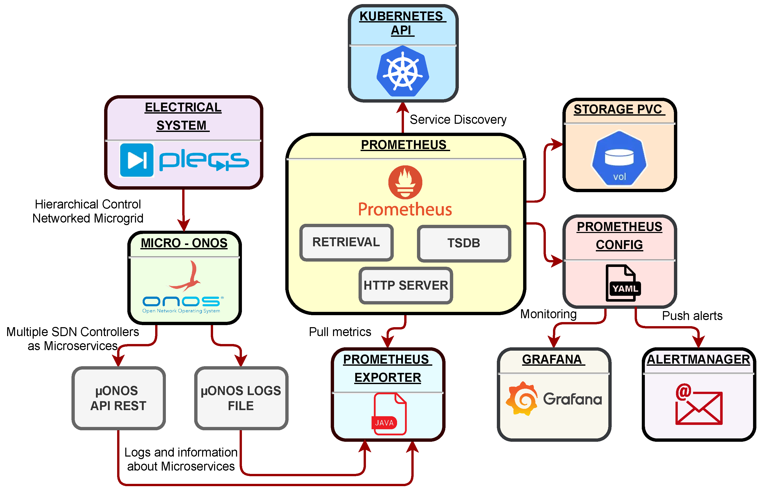
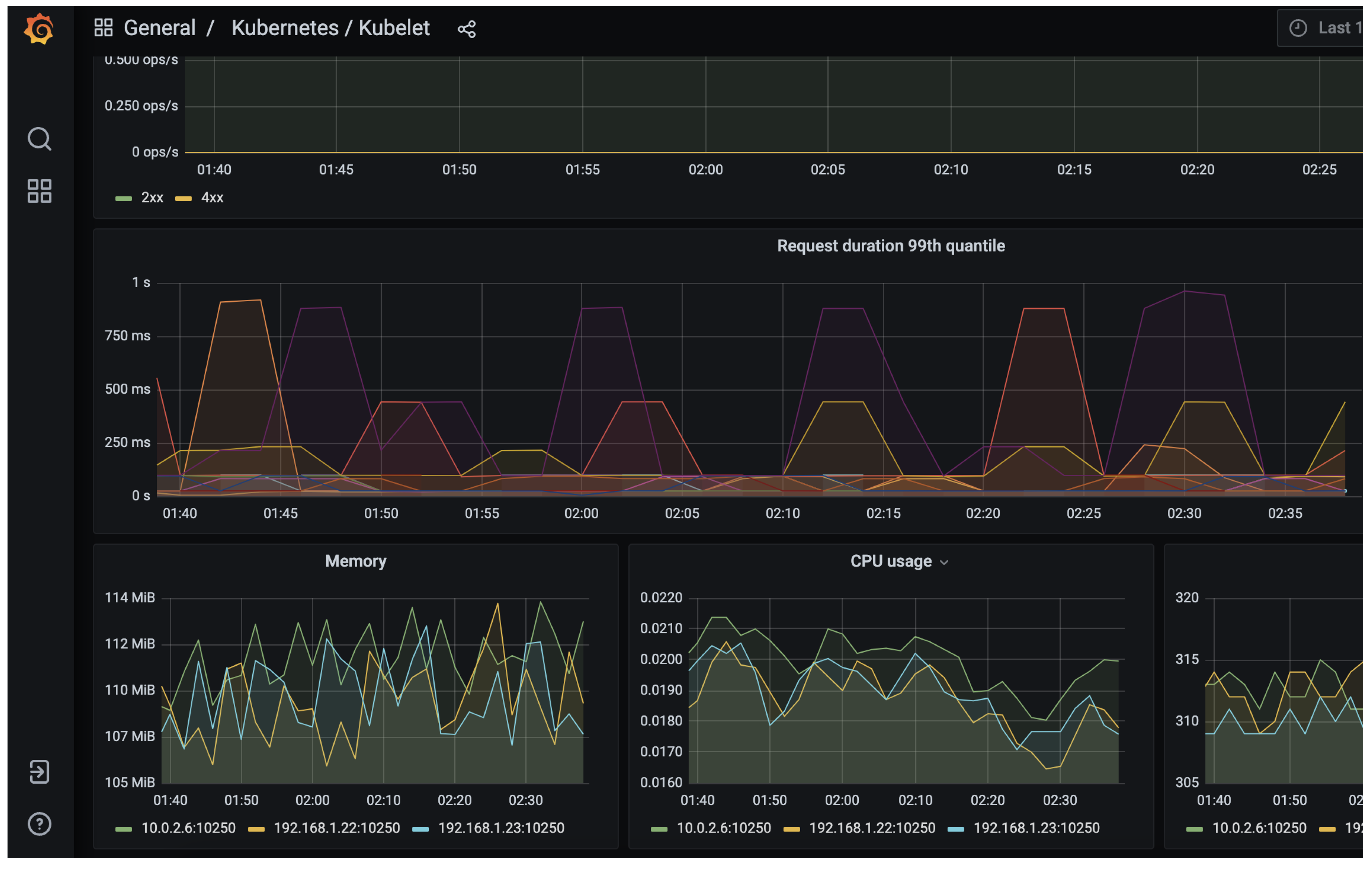
5.5. Monitoring Platform
- Ensure that the nodes in your cluster have enough resources (CPU, memory, storage) to support the increased number of pods. The notification system and the alerts configured in Grafana allow the monitoring of resource usage and global capacity.
- Using horizontal pod autoscaling (HPA) automatically adjusts the number of pods based on resource usage and demand. HPA can be configured based on CPU usage, memory usage, or custom metrics.
- To prevent resource contention and performance issues, pod anti-affinity rules ensure that pods are not placed on the same node. This method avoids the scheduling of pods on the same node.
- Optimize pod resource requests and limits to function correctly.
- Use pod disruption budgets (PDB) to ensure that a minimum number of pods are available during node maintenance or failures. By setting a PDB, you can guarantee that the service is unaffected by removing pods from the cluster.
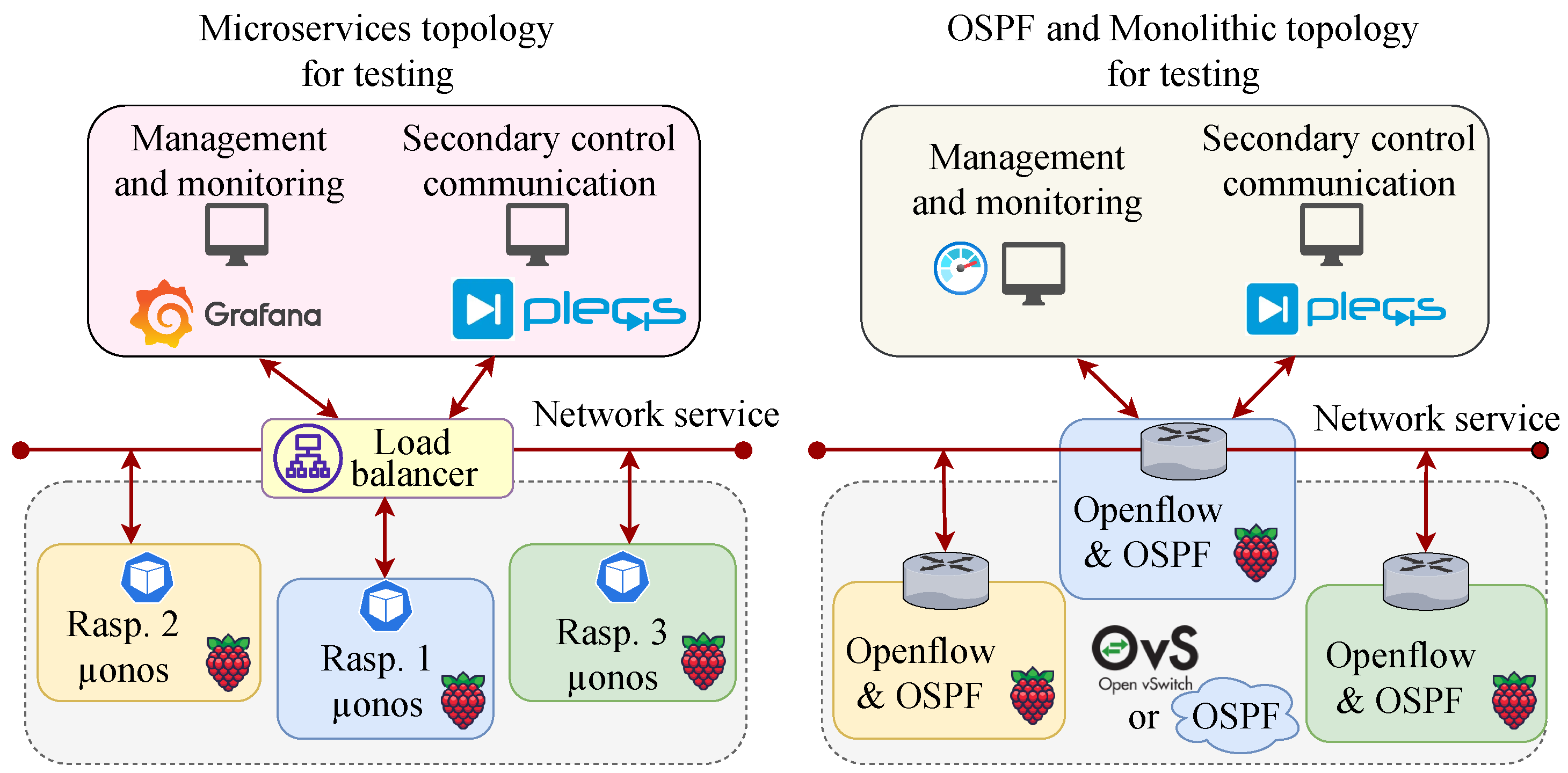
6. Experimental Scenarios and Results
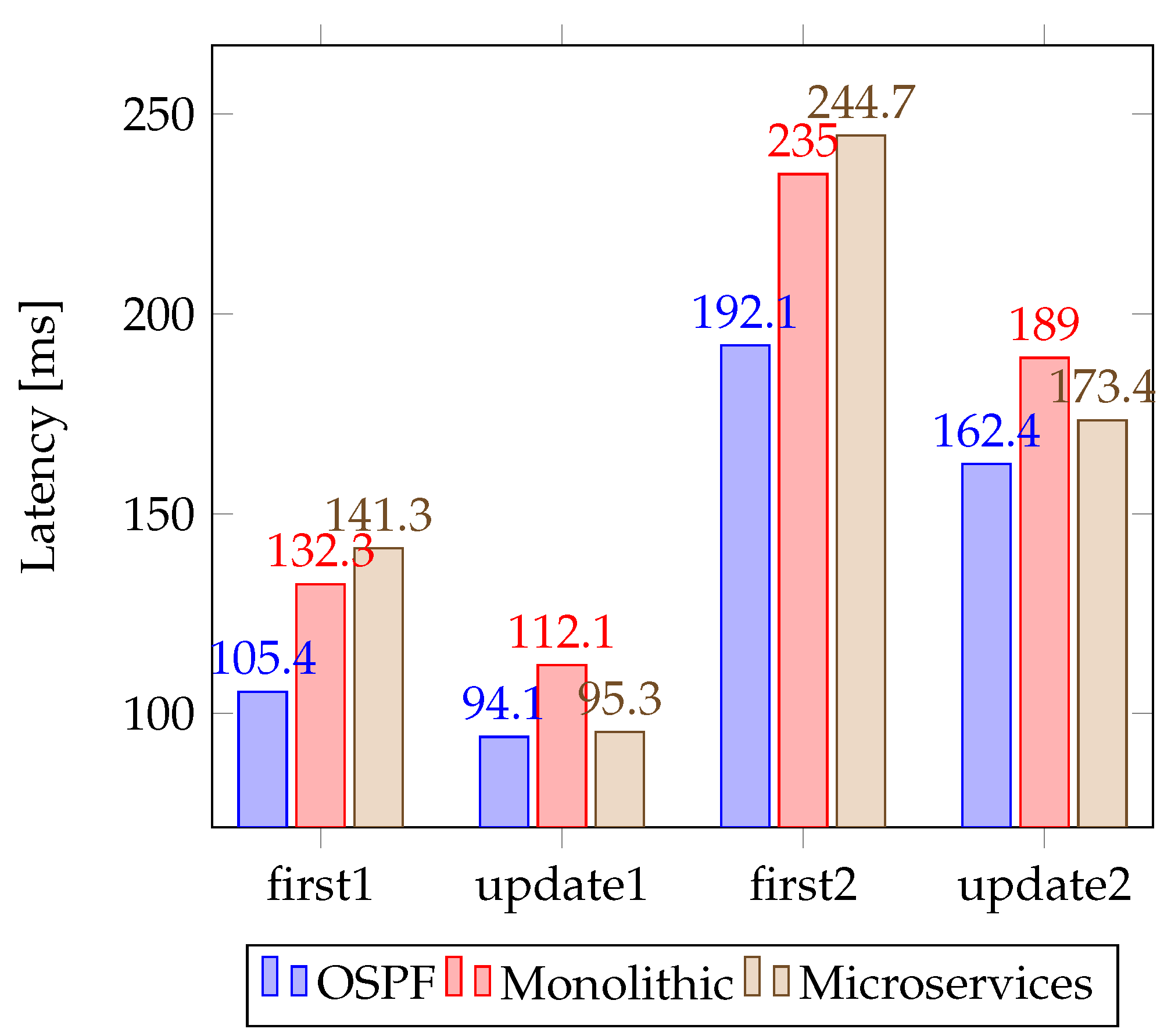
6.1. Latency
- Latency: Regarding latency, OSPF is a distributed protocol that relies on exchanging routing information between devices. It’s designed to find the shortest path between two points, which can help to minimize latency. In general, monolithic architectures can offer lower latency since all the system components are closely integrated and communicate directly, reducing network communication overhead. However, this close coupling can also limit the system’s horizontal scalability and ability to handle high throughput requirements. On the other hand, SDN microservices rely on a central controller that manages the network, and the latency can be affected by the communication between the controller and the devices.
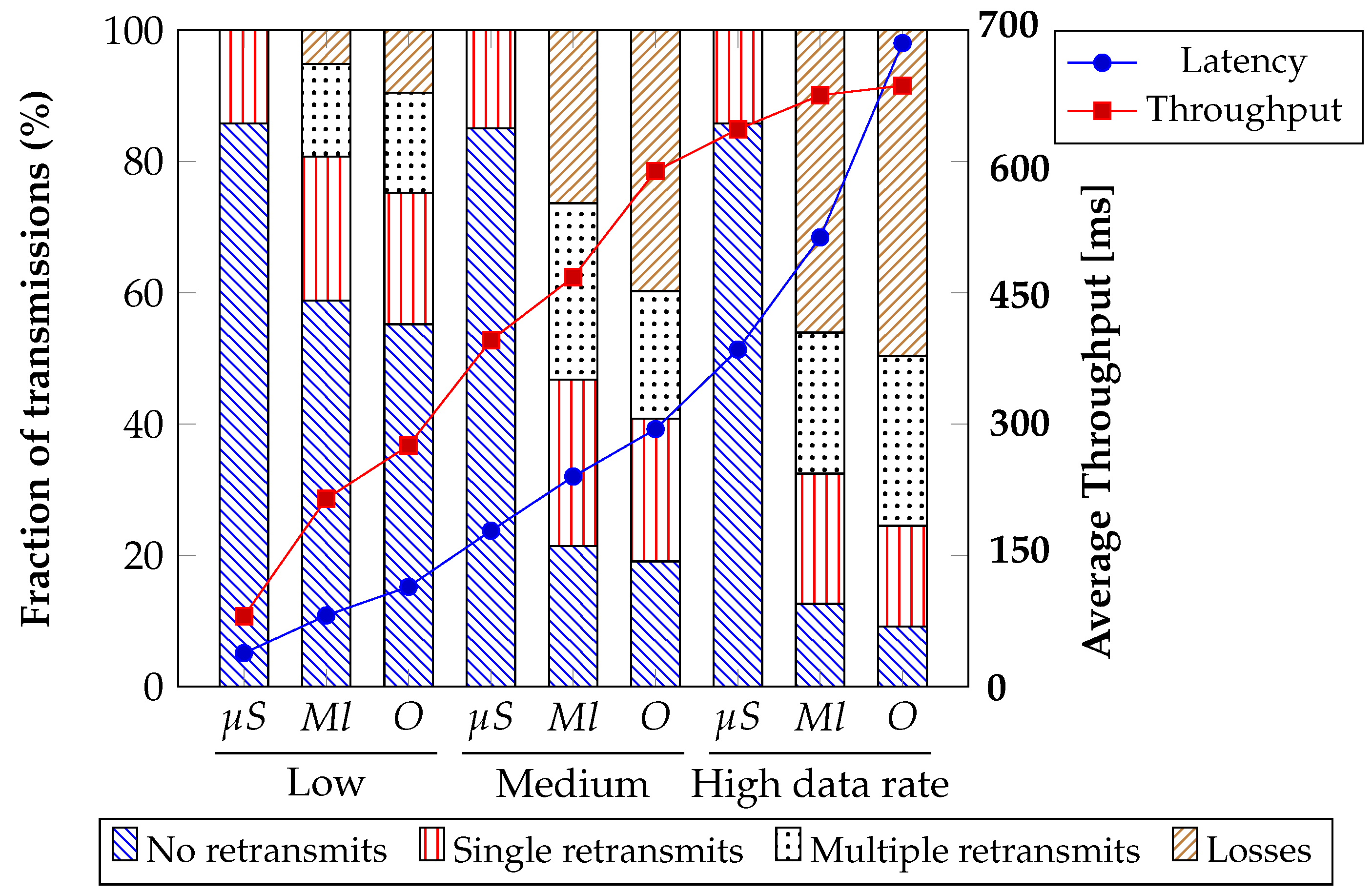
- Throughput: OSPF is a protocol that supports link-state routing and can quickly adapt to network topology changes. As a result, it can provide high throughput in a stable network environment. In contrast, SDN microservices can provide higher throughput as the system can be scaled horizontally by adding more instances of individual services as needed.
- Recovery time: OSPF is designed to support fast convergence and can quickly recover from a link or device failure. However, the convergence time can depend on the size and complexity of the network. SDN microservices can also provide fast recovery times, but it depends on the specific implementation and configuration.
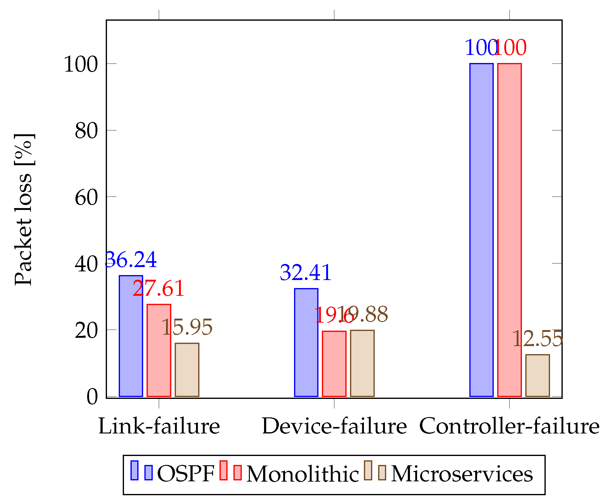
- Link failure: OSPF can detect a link failure and reroute traffic along an alternate path, which helps to maintain connectivity. SDN microservices can also detect link failures and potentially provide more granular control over how traffic is rerouted.
- Device failure: In OSPF, if a device fails, the routing tables are recalculated, and the network can continue to operate. In SDN microservices, the central controller can detect a device failure and reconfigure the network accordingly.
- Controller failure: In SDN microservices, the central controller is a single point of failure. If the controller fails, the network may not be able to operate correctly. However, many SDN solutions provide redundancy and failover mechanisms to minimize the impact of controller failure.
6.2. Throughput
7. Communication Failure and Recovery Test
8. Conclusions
Author Contributions
Funding
Data Availability Statement
Acknowledgments
Conflicts of Interest
Nomenclature
| API | Application Programming Interface |
| SDN | Software-defined networking |
| DGs | Distributed generators |
| NMG | Networked microgrids |
| PLECS | The Simulation Platform for Power Electronic Systems |
| Microservices Open Network Operating System | |
| Bare-metal | Physical device designed to run dedicated services |
| AC/DC | Alternating current/direct current |
| REST API | Representational state transfer for application programming interface |
| VSI | Voltage source inverter |
| RL | Resistive-inductive load |
| P, Q | Active and reactive power |
| MG | Microgrid |
| Frequency | |
| , | Nominal frequency and voltage |
| , | Power input error for droop control |
| , | Constant to handle maximum deviation of the microgrid |
| , | Nominal frequency and voltage |
| Droop control voltage | |
| Voltage across the filter | |
| , | , constant frame |
| , | Filter and output currents |
| Frequency obtained by secondary control | |
| Voltage obtained by secondary control | |
| , | Controller parameters of PI |
| , | Average frequency and voltage broadcasted by each DG |
| QoS | Quality of service |
| K3s | Lightweight Kubernetes |
| ONF | Open Network Foundation |
| gRPC | Remote Procedure Calls |
| gNMI | gRPC Network Management Interface |
| gNOI | gRPC Network Operations Interface |
| NB, SB | North bound and south bound interfaces |
| P4Runtime | Control plane specification for controlling the data plane elements |
| YANG model | Yet another next-generation data modeling language |
| CNI | Kubernetes container network interface |
| CAN | Controller area network protocol |
| SPI | Serial peripheral interface |
| I2C | Inter-Integrated Circuit communication protocol |
| OSPF | Open shortest path first communication protocol |
Appendix A
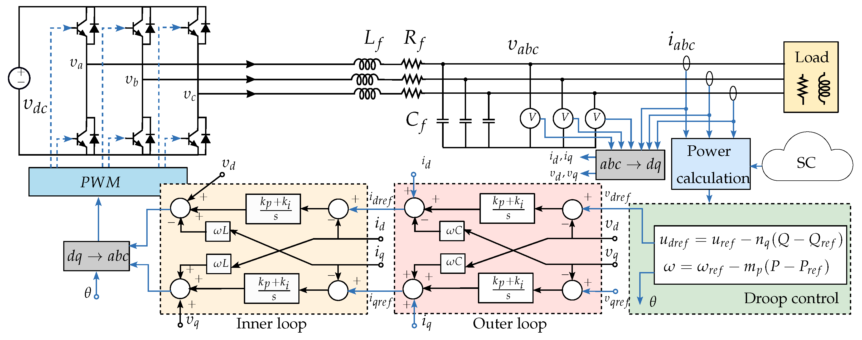
Primary Control
Appendix B
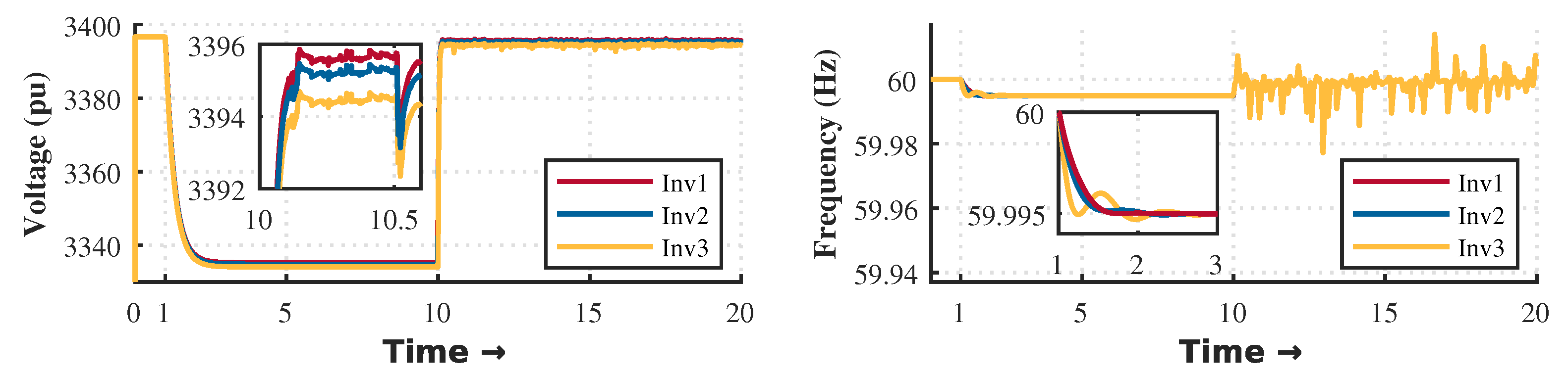
Secondary Control
References
- Tinajero, G.D.A.; Nasir, M.; Vasquez, J.C.; Guerrero, J.M. Comprehensive power flow modelling of hierarchically controlled AC/DC hybrid islanded microgrids. Int. J. Electr. Power Energy Syst. 2021, 127, 106629. [Google Scholar] [CrossRef]
- Han, Y.; Li, H.; Shen, P.; Coelho, E.A.A.; Guerrero, J.M. Review of active and reactive power sharing strategies in hierarchical controlled microgrids. IEEE Trans. Power Electron. 2016, 32, 2427–2451. [Google Scholar] [CrossRef]
- Kulkarni, S.V.; Gaonkar, D.N. Improved droop control strategy for parallel connected power electronic converter based distributed generation sources in an Islanded Microgrid. Electr. Power Syst. Res. 2021, 201, 107531. [Google Scholar] [CrossRef]
- Pérez-Guzmán, R.E.; Salgueiro-Sicilia, Y.; Rivera, M. Communications in smart grids. In Proceedings of the 2017 CHILEAN Conference on Electrical, Electronics Engineering, Information and Communication Technologies (CHILECON), Pucon, Chile, 18–20 October 2017; pp. 1–7. [Google Scholar]
- Simpson-Porco, J.W.; Shafiee, Q.; Dörfler, F.; Vasquez, J.C.; Guerrero, J.M.; Bullo, F. Secondary frequency and voltage control of islanded microgrids via distributed averaging. IEEE Trans. Ind. Electron. 2015, 62, 7025–7038. [Google Scholar] [CrossRef]
- Khayat, Y.; Shafiee, Q.; Heydari, R.; Naderi, M.; Dragičević, T.; Simpson-Porco, J.W.; Dörfler, F.; Fathi, M.; Blaabjerg, F.; Guerrero, J.M.; et al. On the secondary control architectures of AC microgrids: An overview. IEEE Trans. Power Electron. 2019, 35, 6482–6500. [Google Scholar] [CrossRef]
- Ferreira, D.; Silva, S.; Silva, W.; Brandao, D.; Bergna, G.; Tedeschi, E. Overview of Consensus Protocol and Its Application to Microgrid Control. Energies 2022, 15, 8536. [Google Scholar] [CrossRef]
- Shan, Y.; Pan, A.; Liu, H. A switching event-triggered resilient control scheme for primary and secondary levels in AC microgrids. ISA Trans. 2022, 127, 216–228. [Google Scholar] [CrossRef]
- Shafiee, Q.; Dragičević, T.; Vasquez, J.C.; Guerrero, J.M. Hierarchical control for multiple DC-microgrids clusters. IEEE Trans. Energy Convers. 2014, 29, 922–933. [Google Scholar] [CrossRef]
- Zhou, Q.; Shahidehpour, M.; Paaso, A.; Bahramirad, S.; Alabdulwahab, A.; Abusorrah, A. Distributed control and communication strategies in networked microgrids. IEEE Commun. Surv. Tutor. 2020, 22, 2586–2633. [Google Scholar] [CrossRef]
- Yang, L.; Ng, B.; Seah, W.K.; Groves, L.; Singh, D. A survey on network forwarding in Software-Defined Networking. J. Netw. Comput. Appl. 2021, 176, 102947. [Google Scholar] [CrossRef]
- Ndiaye, M.; Hancke, G.P.; Abu-Mahfouz, A.M.; Zhang, H. Software-defined power grids: A survey on opportunities and taxonomy for microgrids. IEEE Access 2021, 9, 98973–98991. [Google Scholar] [CrossRef]
- Ren, L.; Qin, Y.; Li, Y.; Zhang, P.; Wang, B.; Luh, P.B.; Han, S.; Orekan, T.; Gong, T. Enabling resilient distributed power sharing in networked microgrids through software defined networking. Appl. Energy 2018, 210, 1251–1265. [Google Scholar] [CrossRef]
- Ren, L.; Qin, Y.; Wang, B.; Zhang, P.; Luh, P.B.; Jin, R. Enabling Resilient Microgrid Through Programmable Network. IEEE Trans. Smart Grid 2017, 8, 2826–2836. [Google Scholar] [CrossRef]
- Danzi, P.; Angjelichinoski, M.; Stefanovic, C.; Dragicevic, T.; Popovski, P. Software-Defined Microgrid Control for Resilience Against Denial-of-Service Attacks. IEEE Trans. Smart Grid 2019, 10, 5258–5268. [Google Scholar] [CrossRef]
- Comer, D.; Rastegarnia, A. Toward disaggregating the SDN control plane. IEEE Commun. Mag. 2019, 57, 70–75. [Google Scholar] [CrossRef]
- Arzo, S.T.; Scotece, D.; Bassoli, R.; Barattini, D.; Granelli, F.; Foschini, L.; Fitzek, F.H. MSN: A Playground Framework for Design and Evaluation of MicroServices-Based sdN Controller. J. Netw. Syst. Manag. 2022, 30, 1–31. [Google Scholar] [CrossRef]
- Siddiqui, S.; Hameed, S.; Shah, S.A.; Ahmad, I.; Aneiba, A.; Draheim, D.; Dustdar, S. Towards Software-Defined Networking-based IoT Frameworks: A Systematic Literature Review, Taxonomy, Open Challenges and Prospects. IEEE Access 2022, 10, 70850–70901. [Google Scholar] [CrossRef]
- Isong, B.; Molose, R.R.S.; Abu-Mahfouz, A.M.; Dladlu, N. Comprehensive review of SDN controller placement strategies. IEEE Access 2020, 8, 170070–170092. [Google Scholar] [CrossRef]
- Nippon Telegraph and Telephone Corporation (NTT). Ryu SDN Controller. Available online: https://ryu-sdn.org/ (accessed on 22 December 2022).
- OpenDaylight (ODL) Controller. Available online: https://www.opendaylight.org/ (accessed on 3 June 2022).
- ONOS Project Community. Open Network Operating System (ONOS). Available online: https://opennetworking.org/onos/ (accessed on 18 January 2023).
- Markelov, A. OpenStack Networking. In Certified OpenStack Administrator Study Guide; Springer: Berlin/Heidelberg, Germany, 2022; pp. 77–121. [Google Scholar]
- Hölscher, A.; Asplund, M.; Boeira, F. Evaluation of an SDN-based Microservice Architecture. In Proceedings of the 2022 IEEE 8th International Conference on Network Softwarization (NetSoft), Milan, Italy, 27 June–1 July 2022; pp. 151–156. [Google Scholar]
- Open Network Foundation. Open Network Operating System (ONOS). Available online: https://docs.onosproject.org/ (accessed on 22 October 2022).
- Ray, P.P.; Kumar, N. SDN/NFV architectures for edge-cloud oriented IoT: A systematic review. Comput. Commun. 2021, 169, 129–153. [Google Scholar] [CrossRef]
- Okwuibe, J.; Haavisto, J.; Harjula, E.; Ahmad, I.; Ylianttila, M. SDN enhanced resource orchestration of containerized edge applications for industrial IoT. IEEE Access 2020, 8, 229117–229131. [Google Scholar] [CrossRef]
- Nsafoa-Yeboah, K.; Tchao, E.T.; Yeboah-Akowuah, B.; Kommey, B.; Agbemenu, A.S.; Keelson, E.; Monirujjaman Khan, M. Software-Defined Networks for Optical Networks Using Flexible Orchestration: Advances, Challenges, and Opportunities. J. Comput. Netw. Commun. 2022, 2022, 5037702. [Google Scholar] [CrossRef]
- Marzal, S.; Salas, R.; González-Medina, R.; Garcerá, G.; Figueres, E. Current challenges and future trends in the field of communication architectures for microgrids. Renew. Sustain. Energy Rev. 2018, 82, 3610–3622. [Google Scholar] [CrossRef]
- Abbasi, M.; Abbasi, E.; Li, L.; Aguilera, R.P.; Lu, D.; Wang, F. Review on the Microgrid Concept, Structures, Components, Communication Systems, and Control Methods. Energies 2023, 16, 484. [Google Scholar] [CrossRef]
- Lévy, L.N.; Bosom, J.; Guerard, G.; Amor, S.B.; Bui, M.; Tran, H. DevOps Model Appproach for Monitoring Smart Energy Systems. Energies 2022, 15, 5516. [Google Scholar] [CrossRef]
- Johansson, B.; Rågberger, M.; Nolte, T.; Papadopoulos, A.V. Kubernetes orchestration of high availability distributed control systems. In Proceedings of the 2022 IEEE International Conference on Industrial Technology (ICIT), Shanghai, China, 22–25 August 2022; pp. 1–8. [Google Scholar]
- Zhu, C.; Han, B.; Zhao, Y. A Comparative Study of Spark on the bare metal and Kubernetes. In Proceedings of the 2020 6th International Conference on Big Data and Information Analytics (BigDIA), Shenzhen, China, 4–6 December 2020; pp. 117–124. [Google Scholar]
- Huedo, E.; Montero, R.S.; Moreno-Vozmediano, R.; Vázquez, C.; Holer, V.; Llorente, I.M. Opportunistic deployment of distributed edge clouds for latency-critical applications. J. Grid Comput. 2021, 19, 1–16. [Google Scholar] [CrossRef]
- Tonini, F.; Natalino, C.; Temesgene, D.A.; Ghebretensaé, Z.; Wosinska, L.; Monti, P. Benefits of Pod dimensioning with best-effort resources in bare metal cloud native deployments. IEEE Netw. Lett. 2023, 5, 41–45. [Google Scholar] [CrossRef]
- Klos, A.; Rosenbaum, M.; Schiffmann, W. Scalable and highly available multi-objective neural architecture search in bare metal kubernetes cluster. In Proceedings of the 2021 IEEE International Parallel and Distributed Processing Symposium Workshops (IPDPSW), Portland, OR, USA, 17–21 June 2021; pp. 605–610. [Google Scholar]
- Guzmán, R.E.P.; Rivera, M.; Wheeler, P.W.; Mirzaeva, G.; Espinosa, E.E.; Rohten, J.A. Microgrid Power Sharing Framework for Software Defined Networking and Cybersecurity Analysis. IEEE Access 2022, 10, 111389–111405. [Google Scholar] [CrossRef]
- Yadav, G.; Joshi, D.; Gopinath, L.; Soni, M.K. Reliability and Availability Optimization of Smart Microgrid Using Specific Configuration of Renewable Resources and Considering Subcomponent Faults. Energies 2022, 15, 5994. [Google Scholar] [CrossRef]
- Ahmad, S.; Mir, A.H. Scalability, Consistency, Reliability and Security in SDN Controllers: A Survey of Diverse SDN Controllers. J. Netw. Syst. Manag. 2021, 29, 9. [Google Scholar] [CrossRef]
- Mokhtar, H.; Di, X.; Zhou, Y.; Hassan, A.; Ma, Z.; Musa, S. Multiple-level threshold load balancing in distributed SDN controllers. Comput. Netw. 2021, 198, 108369. [Google Scholar] [CrossRef]
- Gupta, N.; Maashi, M.S.; Tanwar, S.; Badotra, S.; Aljebreen, M.; Bharany, S. A Comparative Study of Software Defined Networking Controllers Using Mininet. Electronics 2022, 11, 2715. [Google Scholar] [CrossRef]
- Guerrero, J.M.; Vasquez, J.C.; Matas, J.; De Vicu na, L.G.; Castilla, M. Hierarchical control of droop-controlled AC and DC microgrids—A general approach toward standardization. IEEE Trans. Ind. Electron. 2010, 58, 158–172. [Google Scholar] [CrossRef]
- Garces, L. Microgrid in Island Operation. 2022. Available online: https://www.plexim.com/support/application-examples/1259 (accessed on 3 December 2022).
- Garces, L.J.; Liu, Y.; Bose, S. System and Method for Integrating Wind and Hydroelectric Generation and Pumped Hydro Energy Storage Systems. U.S. Patent 7,239,035, 3 July 2007. [Google Scholar]
- Zargar, R.H.M.; Yaghmaee, M.H. Energy exchange cooperative model in SDN-based interconnected multi-microgrids. Sustain. Energy Grids Netw. 2021, 27, 100491. [Google Scholar] [CrossRef]
- Khorsandroo, S.; Gallego Sanchez, A.; Tosun, A.S.; Arco, J.; Doriguzzi-Corin, R. Hybrid SDN evolution: A comprehensive survey of the state-of-the-art. Comput. Netw. 2021, 192, 107981. [Google Scholar] [CrossRef]
- Biswas, R.; Wu, J. Traffic Engineering to Minimize the Number of Rules in SDN Datacenters. IEEE Trans. Netw. Sci. Eng. 2021, 8, 1467–1477. [Google Scholar] [CrossRef]
- Miguel-Alonso, J. A Research Review of OpenFlow for Datacenter Networking. IEEE Access 2022, 11, 770–786. [Google Scholar] [CrossRef]
- CNC Foundations. Available online: https://k3s.io/ (accessed on 25 November 2022).
- Labs, R. Rancher: Enterprise Kubernetes Management. Available online: https://www.rancher.com/ (accessed on 25 November 2022).
- Wazirali, R.; Ahmad, R.; Alhiyari, S. SDN-OpenFlow Topology Discovery: An Overview of Performance Issues. Appl. Sci.-Basel 2021, 11, 6999. [Google Scholar] [CrossRef]
- Yan, L.; Sheikholeslami, M.; Gong, W.; Shahidehpour, M.; Li, Z. Architecture, Control, and Implementation of Networked Microgrids for Future Distribution Systems. J. Mod. Power Syst. Clean Energy 2022, 10, 286–299. [Google Scholar] [CrossRef]
- Siva Ananmalay, J.A.; Barton, D. Open Networking Foundation. 2022. Available online: https://opennetworking.org/ (accessed on 16 July 2022).
- Vachuska, T. ONOS Helm Charts. 2023. Available online: https://github.com/onosproject/onos-helm-charts (accessed on 3 December 2022).
- Vachuska, T.; Halterman, J. Atomix-Controller: Kubernetes Controller for Atomix 4. Available online: https://github.com/atomix/atomix-controller (accessed on 16 July 2022).
- Open Network Foundation. Deploying Onos-Config. Available online: https://docs.onosproject.org/onos-config/docs/deployment/ (accessed on 7 December 2022).
- Pérez, R. Deploy HA Kubernetes Cluster for SDN Microgrid Hierarchical Control. 2023. Available online: https://github.com/ricardopg1987/kubernetes-rpi (accessed on 3 December 2022).
- CNC Foundations. Available online: https://docs.k3s.io/installation/ha-embedded (accessed on 25 September 2022).
- KubeSphere. Set up an HA Kubernetes Cluster Using Keepalived and HAproxy. 2023. Available online: https://kubesphere.io/docs/v3.3/installing-on-linux/high-availability-configurations/set-up-ha-cluster-using-keepalived-haproxy/ (accessed on 25 September 2022).
- Zhang, Z. A comparison of low-speed communication modes. In Proceedings of the International Conference on Network Communication and Information Security (ICNCIS 2021), Qingdao, China, 19–21 August 2022; Volume 12175, pp. 38–43. [Google Scholar]
- ZodiacFX Communication Device. Available online: https://www.cryptomuseum.com/radio/zodiac/ (accessed on 17 March 2023).
- Muhammad, A.; Saqib, M.; Song, W.C. Sensor Virtualization and Data Orchestration in Internet of Vehicles (IoV). In Proceedings of the 2021 IFIP/IEEE International Symposium on Integrated Network Management (IM), Bordeaux, France, 18–20 May 2021; pp. 998–1003. [Google Scholar]
- Heydari, R.; Dragicevic, T.; Blaabjerg, F. High-bandwidth secondary voltage and frequency control of vsc-based ac microgrid. IEEE Trans. Power Electron. 2019, 34, 11320–11331. [Google Scholar] [CrossRef]
- Dragičević, T. Model predictive control of power converters for robust and fast operation of AC microgrids. IEEE Trans. Power Electron. 2017, 33, 6304–6317. [Google Scholar] [CrossRef]
- Villalón, A.; Rivera, M.; Salgueiro, Y.; Mu noz, J.; Dragičević, T.; Blaabjerg, F. Predictive control for microgrid applications: A review study. Energies 2020, 13, 2454. [Google Scholar] [CrossRef]


| Metric | Monolithic | Microservices |
|---|---|---|
| Resiliency | The whole system can be affected by a bug, communication or device failure, or security issues. | Other services are not affected by a failure in a particular microservice. |
| Deployment | Simple and fast deployment architecture. | Orchestrating the deployment becomes complex due to communication and hardware. restrictions. |
| Scalability | Redeploying the entire system to manage new changes make it difficult to manage and maintain. | You can scale each element independently without experiencing any downtime. |
| Compatibility | Adopting new technology languages or frameworks is impossible due to the lack of flexibility. | Multiple integration and standardization. |
| Security | Communication within a single unit secure data processing. | The use of APIs to communicate different services produces some security threats. |
| Development | The huge indivisible database makes distributing the team’s efforts impossible. | Each component can be independently operated by a team of developers. |
| Item | Quantity | Unit Price in USD |
|---|---|---|
| Raspberry pi 4B 8 GB | 3 | 170 |
| SanDisk Micro SD card 32 GB | 3 | 5 |
| Adapter USB to Ethernet | 4 | 10 |
| 0.5 m CAT6 Ethernet cables | 4 | 4.5 |
| Router Cisco 891F (not necessary) | 1 | 670 |
| Total cost | 1248 |
| Item | Value |
|---|---|
| Microgrid parameter | |
| Rated frequency | 60 [Hz] |
| Rated voltage | [V] |
| Load power rating RES1 | 1 [MVA] |
| Load power rating RES2 | 500 [kVA] |
| Load power rating RES3 | 200 [kVA] |
| 0.4 [mH] | |
| 0.65 [mH] | |
| 0.9 [mH] | |
| Filter (L,C) | 1.8 [mH], [25 µF] |
| , , | , 12.5 [mH], 5 [mF] |
| Sample time (Ts) | 10 [kHz] |
| Primary control parameters | |
| P - Droop Coeff. | 1 [] |
| Q - V Droop Coeff. | 25 [] |
| Frequency proportional term | 0.01 |
| Frequency integral term | 3 s |
| Voltage proportional term | 0.01 |
| Voltage integral term | 2 s |
| Secondary control parameters | |
| Frequency proportional term | 0.001 |
| Frequency integral term | 4 s |
| Voltage proportional term | 0.001 |
| Voltage integral term | 6 s |
| Microservices vs. OSPF | Paired Differences | Improvements | ||
|---|---|---|---|---|
| Mean | Std. Deviation | Std. Error | ||
| Latency of first package | −17.41 | 13.12 | 2.39 | −29.74% |
| Overall Latency | −20.66 | 32.41 | 6.01 | −4.75% |
| Throughput | 14.28 | 5.24 | 0.95 | −4.15% |
| Recovery time | 214.82 | 39.95 | 7.29 | 53.41% |
| Packet loss-link failure | 19.75 | 2.06 | 0.37 | 55.98% |
| Packet loss-device failure | 11.83 | 2.30 | 0.42 | 38.66% |
| Packet loss-controller failure | 86.00 | 1.38 | 0.25 | 100% |
| Microservices vs. OSPF | Paired Differences | Improvements | ||
| Mean | Std. Deviation | Std. Error | ||
| Latency of first package | 8.46 | 14.02 | 2.56 | −5.09% |
| Overall Latency | 32.91 | 38.79 | 7.20 | 10.76% |
| Throughput | −50.47 | 5.96 | 1.08 | 7.05% |
| Recovery time | 257.50 | 36.23 | 6.61 | 36.58% |
| Packet loss-link failure | 13.01 | 2.21 | 0.40 | 42.23% |
| Packet loss-device failure | −1.13 | 2.41 | 0.44 | −1.42% |
| Packet loss-controller failure | 85.83 | 1.38 | 0.25 | 100% |
| Communication Protocols | Recovery Time |
|---|---|
| OSPF | ms |
| Monolithic controller | ms |
| Microservices controller | ms |
Disclaimer/Publisher’s Note: The statements, opinions and data contained in all publications are solely those of the individual author(s) and contributor(s) and not of MDPI and/or the editor(s). MDPI and/or the editor(s) disclaim responsibility for any injury to people or property resulting from any ideas, methods, instructions or products referred to in the content. |
© 2023 by the authors. Licensee MDPI, Basel, Switzerland. This article is an open access article distributed under the terms and conditions of the Creative Commons Attribution (CC BY) license (https://creativecommons.org/licenses/by/4.0/).
Share and Cite
Pérez, R.; Rivera, M.; Salgueiro, Y.; Baier, C.R.; Wheeler, P. Moving Microgrid Hierarchical Control to an SDN-Based Kubernetes Cluster: A Framework for Reliable and Flexible Energy Distribution. Sensors 2023, 23, 3395. https://doi.org/10.3390/s23073395
Pérez R, Rivera M, Salgueiro Y, Baier CR, Wheeler P. Moving Microgrid Hierarchical Control to an SDN-Based Kubernetes Cluster: A Framework for Reliable and Flexible Energy Distribution. Sensors. 2023; 23(7):3395. https://doi.org/10.3390/s23073395
Chicago/Turabian StylePérez, Ricardo, Marco Rivera, Yamisleydi Salgueiro, Carlos R. Baier, and Patrick Wheeler. 2023. "Moving Microgrid Hierarchical Control to an SDN-Based Kubernetes Cluster: A Framework for Reliable and Flexible Energy Distribution" Sensors 23, no. 7: 3395. https://doi.org/10.3390/s23073395
APA StylePérez, R., Rivera, M., Salgueiro, Y., Baier, C. R., & Wheeler, P. (2023). Moving Microgrid Hierarchical Control to an SDN-Based Kubernetes Cluster: A Framework for Reliable and Flexible Energy Distribution. Sensors, 23(7), 3395. https://doi.org/10.3390/s23073395