

Triggering Magnets for Wiegand Sensors: Electrodeposited and Origami-Magnetized CoNiP Micro-Magnets


Abstract
1. Introduction
2. Materials and Methods
2.1. Triggering Magnets and Material Characterization
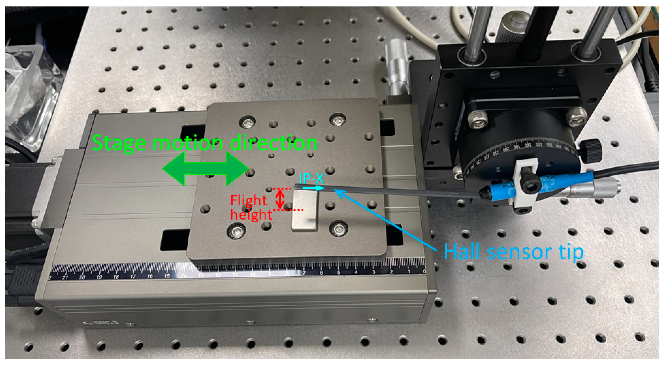
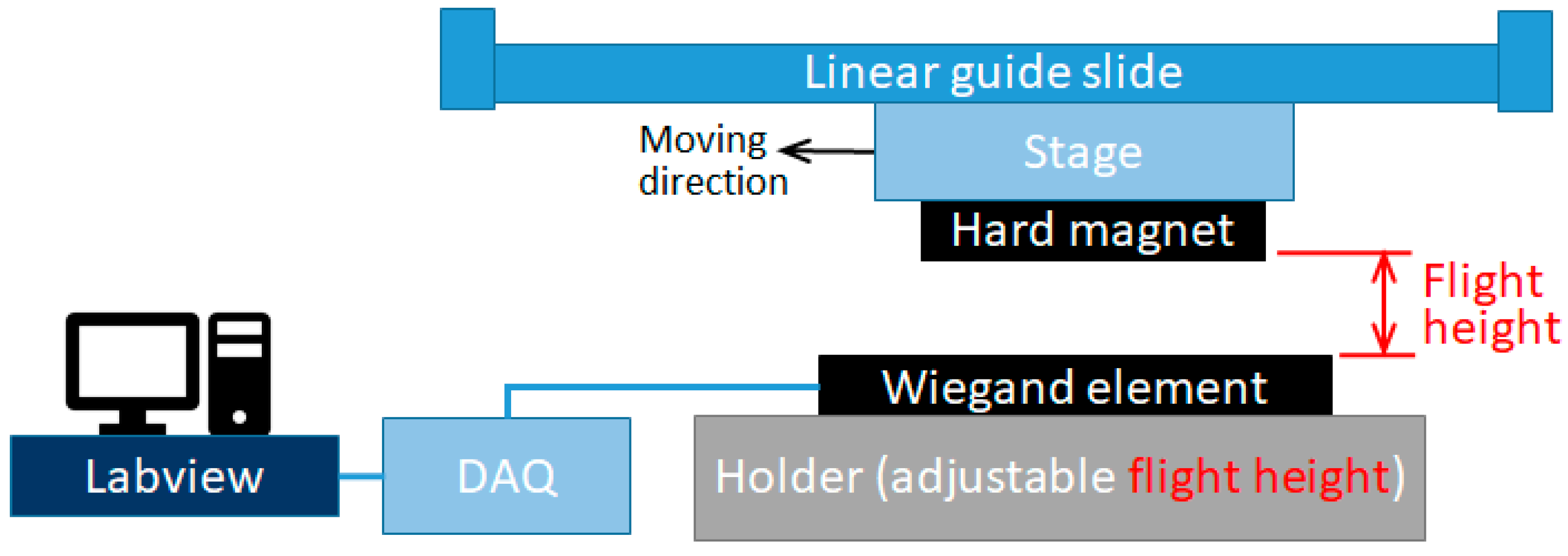
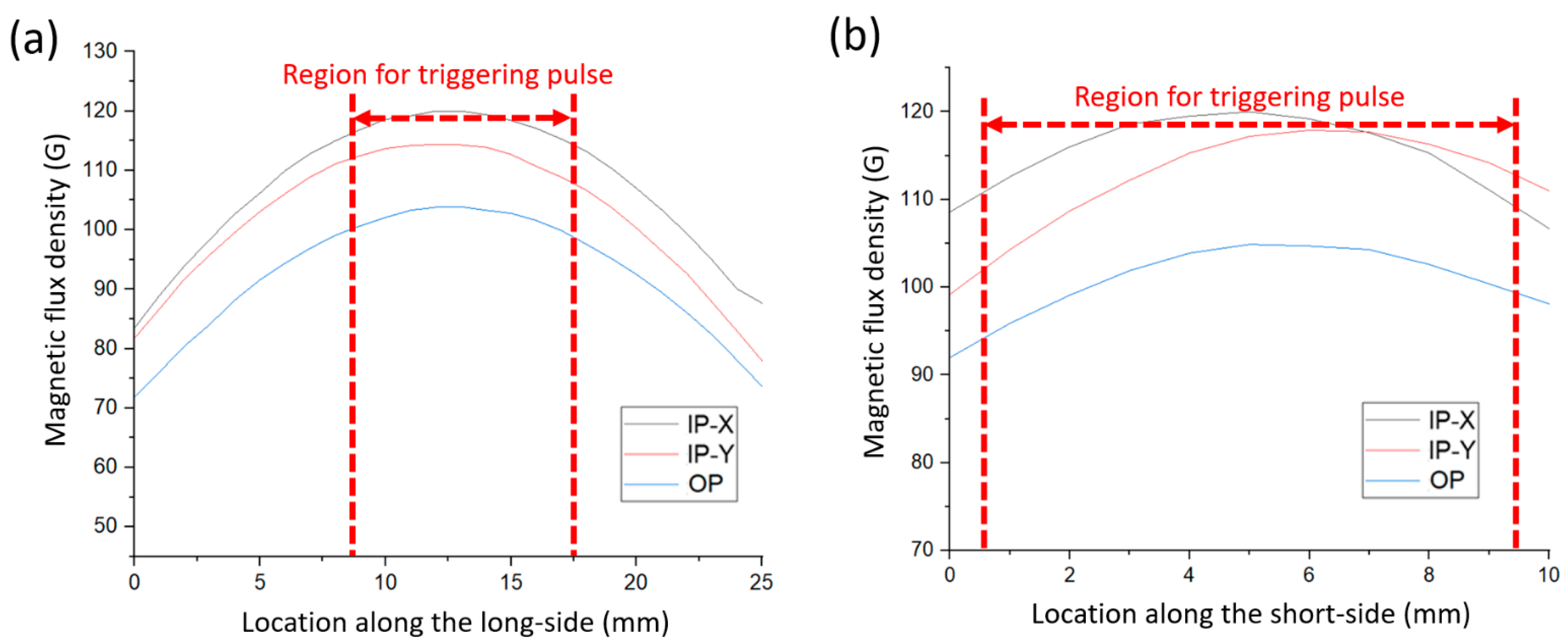
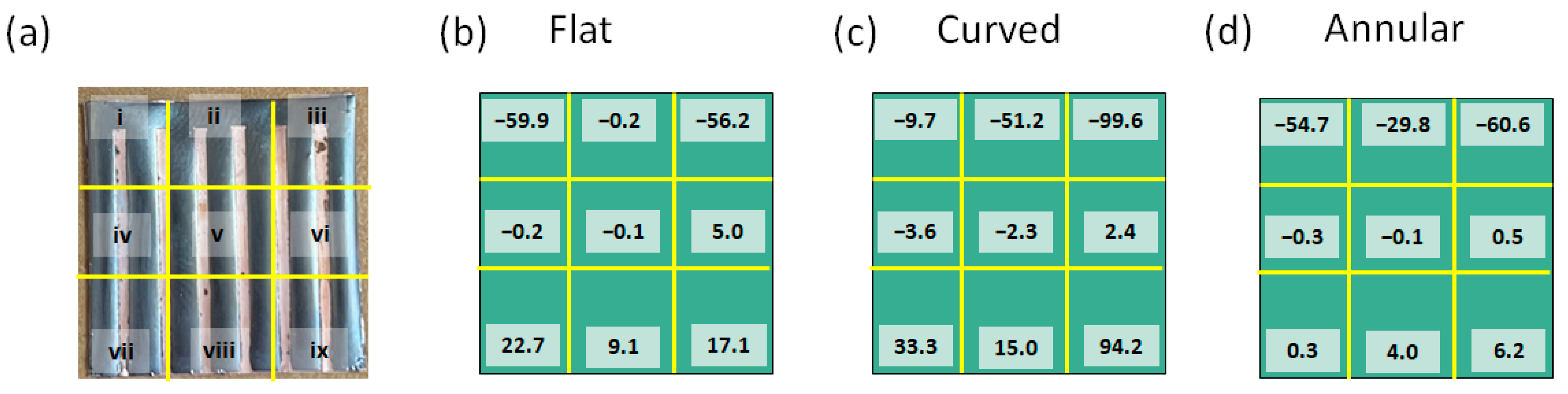
2.2. Origami Magnetization and Measurement of the Magnetic Field Profile
2.3. Output Voltage Measurement of the Triggered Wiegand Pulses
3. Results and Discussion
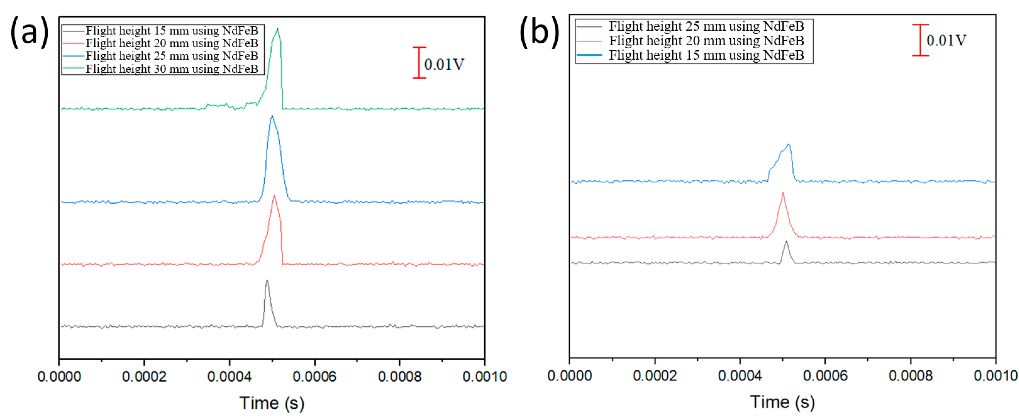
3.1. NdFeB Magnets and Output Pulses
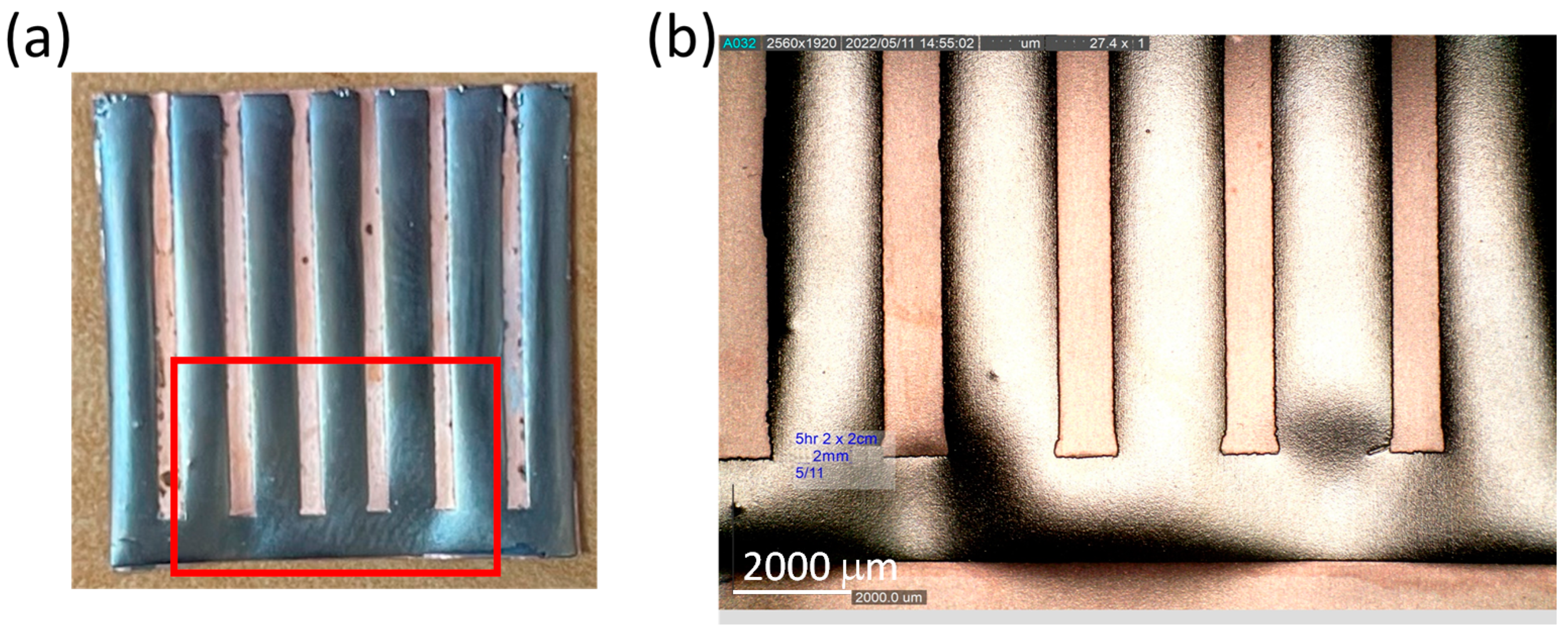
3.2. Microfabrication and Origami Magnetization of CoNiP Micro-Magnets
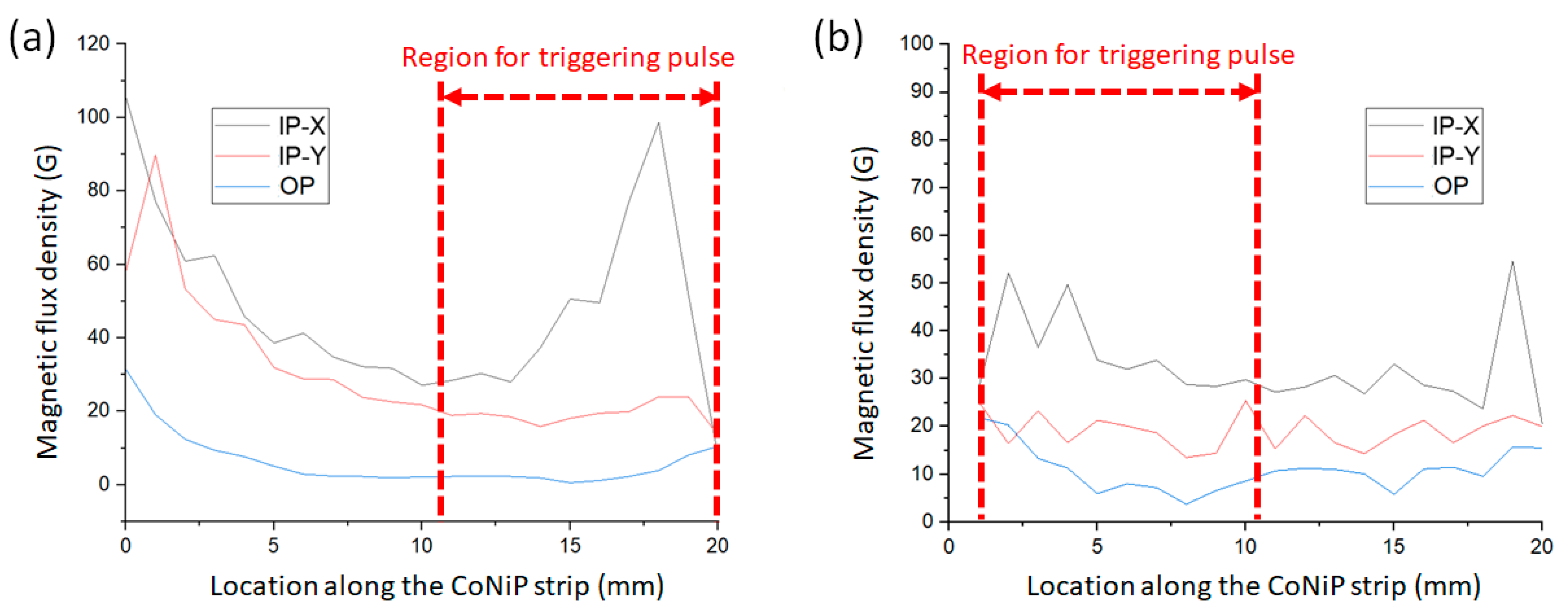
3.3. CoNiP Micro-Magnets and Output Pulses
4. Conclusions
Author Contributions
Funding
Institutional Review Board Statement
Informed Consent Statement
Data Availability Statement
Acknowledgments
Conflicts of Interest
References
- Mohammed, A.K.; Jian, S.; Bodong, L.; Alexander, P.; Jürgen, K. Magnetic sensors-A review and recent technologies. Eng. Res. Express 2021, 3, 022005. [Google Scholar] [CrossRef]
- Pallás-Areny, R.; Webster, J.G. Sensors and Signal Conditioning, 2nd ed.; John Wiley & Sons: Hoboken, NJ, USA, 2001; pp. 254–256. Available online: https://books.google.com/books?hl=en&lr=&id=BDmQDQAAQBAJ&oi=fnd&pg=PR3&ots=z8apbWKnPS&sig=KdtYatucNSfIuLgLjPbg6GCm4yk (accessed on 23 June 2023).
- Wiegand, J.R. Multiple Pulse Magnetic Memory Units. U.S. Patent 3602906, 31 August 1971. Available online: https://scholar.google.com/scholar_lookup?title=Multiple+Pulse+Magnetic+Memory+Units&author=Wiegand,+J.R.&publication_year=1971 (accessed on 23 June 2023).
- Wiegand, J.R. Bistable Magnetic Device. U.S. Patent 3820090, 25 June 1974. Available online: https://scholar.google.com/scholar_lookup?title=Bistable+Magnetic+Device&author=Wiegand,+J.R.&publication_year=1974 (accessed on 23 June 2023).
- Wiegand, J.R. Method of Manufacturing Bistable Magnetic Device. U.S. Patent 3892118, 1 July 1975. Available online: https://scholar.google.com/scholar_lookup?title=Method+of+Manufacturing+Bistable+Magnetic+Device&author=Wiegand,+J.R.&publication_year=1975 (accessed on 23 June 2023).
- Yang, C.; Sakai, T.; Yamada, T.; Song, Z.; Takemura, Y. Improvement of pulse voltage generated by Wiegand sensor through magnetic-flux guidance. Sensors 2020, 20, 1408. [Google Scholar] [CrossRef]
- Lin, C.-C.; Tseng, Y.-C.; Chin, T.-S. A review of the self-powered Wiegand sensor and its applications. Magnetochemistry 2022, 8, 128. [Google Scholar] [CrossRef]
- Iob, F.; Saggini, S.; Ursino, M.; Takemura, Y. A novel wireless charging technique for low-power devices based on Wiegand transducer. IEEE J. Emerg. Sel. Top. Power Electron. 2023, 11, 372–383. [Google Scholar] [CrossRef]
- Díez, P.L.; Gabilondo, I.; Alarcón, E.; Moll, F. Mechanical energy harvesting taxonomy for industrial environments: Application to the railway industry. IEEE Trans. Intell. Transp. Syst. 2020, 21, 2696. [Google Scholar] [CrossRef]
- Lien, H.-L.; Chang, J.-Y. Magnetic reference mark in a linear positioning system generated by a single Wiegand pulse. Sensors 2022, 22, 3185. [Google Scholar] [CrossRef] [PubMed]
- Yao, R.; Takemura, Y.; Uchiyama, T. High precision MI sensor with low energy consumption driven by low-frequency Wiegand pulse. AIP Adv. 2023, 13, 025201. [Google Scholar] [CrossRef]
- Takebuchi, A.; Yamada, T.; Takemura, Y. Reduction of vibration amplitude in vibration-type electricity generator using magnetic wire. J. Mag. Soc. Jpn. 2017, 41, 34–40. [Google Scholar] [CrossRef]
- Takemura, Y.; Fujinaga, N.; Takebuchi, A.; Yamada, T. Batteryless Hall sensor operated by energy harvesting from a single Wiegand pulse. IEEE Trans. Magn. 2017, 53, 4002706. [Google Scholar] [CrossRef]
- Sha, G.; Kita, Y.; Shigeta, H.; Nakamura, T.; Yang, C.; Song, Z.; Takemura, Y. Magnetization state and magnetic structure of Wiegand wire evaluated by external magnetic field measurement. IEEE Trans. Magn. 2023, in press. [Google Scholar] [CrossRef]
- Liakopoulos, T.M.; Zhang, W.; Ahn, C.H. Electroplated Thick CoNiMnP Permanent Magnet Arrays for Micromachined Magnetic Device Applications. In Proceedings of the Ninth International Workshop on Micro Electromechanical Systems, San Diego, CA, USA, 11–15 February 1996; pp. 79–84. [Google Scholar]
- Han, M.; Yuan, Q.; Sun, X. Design and fabrication of integrated magnetic MEMS energy harvester for low frequency applications. J. Microelectromech. Syst. 2014, 23, 204–212. [Google Scholar] [CrossRef]
- Myung, N.V.; Park, D.Y.; Yoo, B.Y.; Sumodjo, P.T.A. Development of electroplated magnetic materials for MEMS. J. Magn. Magn. Mater. 2003, 265, 189–198. [Google Scholar] [CrossRef]
- Xu, Z.-H.; Tseng, B.-H.; Ching, C.; Wang, S.-C.; Chin, T.-S.; Sung, C.-K. Grooved multi-pole magnetic gratings for high-resolution positioning systems. Jpn. J. Appl. Phys. 2015, 54, 06FP01. [Google Scholar] [CrossRef]
- Sharma, S.; Radulov, I.; Major, M.; Alff, L. Evolution of magnetic anisotropy with Sm contents in Sm–Co thin films. IEEE Trans. Magn. 2018, 54, 2102705. [Google Scholar] [CrossRef]
- Reimer, T.; Lofink, F.; Lisec, T.; Thede, C.; Chemnitz, S.; Wagner, B. Temperature-stable NdFeB micromagnets with high-energy density compatible with CMOS back end of line technology. MRS Adv. 2016, 1, 209–213. [Google Scholar] [CrossRef]
- Sun, X.; Yuan, Q.; Fang, D.; Zhang, H. Electrodeposition and characterization of CoNiMnP permanent magnet arrays for MEMS sensors and actuators. Sens. Actuators A 2012, 188, 190–197. [Google Scholar] [CrossRef]
- Li, Y.; Kim, J.; Kim, M.; Armutlulu, A.; Allen, M.G. Thick multilayered micromachined permanent magnets with preserved magnetic properties. J. Microelectromech. Syst. 2016, 25, 498–507. [Google Scholar] [CrossRef]
- Siang, J.; Lim, M.H.; Leong, M.S. Review of vibration-based energy harvesting technology: Mechanism and architectural approach. Int. J. Energy Res. 2018, 42, 1866–1893. [Google Scholar] [CrossRef]
- Qiao, G.Y.; Xiao, F.R. Effects of grain size on the properties of bulk nanocrystalline Co-Ni alloys. Mater. Res. Express 2017, 4, 086512. [Google Scholar] [CrossRef]
- Lu, N.; Li, Y.; Cai, J.; Li, L. Synthesis and characterization of ultrasonic-assisted electroplated Co-P films with amorphous and nanocrystalline structures. IEEE Trans. Magn. 2011, 47, 3799–3802. [Google Scholar] [CrossRef]
- Wu, C.-W.; Lin, C.-C.; Chin, T.-S.; Chang, J.-Y.; Sung, C.-K. Effects of cathode rotation and substrate materials on electrodeposited CoMnP thick films. Mater. Res. Express 2020, 8, 016103. [Google Scholar] [CrossRef]
- Wang, Z.K.; Feng, E.X.; Liu, Q.F.; Wang, J.B.; Xue, D.S. Tuning stress-induced magnetic anisotropy and high frequency properties of FeCo films deposited on different curvature substrates. Phys. B Condens. Matter. 2012, 407, 3872–3875. [Google Scholar] [CrossRef]
- Chen, Y.-S.; Lin, C.-C.; Chin, T.-S.; Chang, J.-Y.; Sung, C.-K. Residual stress tuned magnetic properties of thick CoMnP/Cu multilayers. AIP Adv. 2022, 12, 035022. [Google Scholar] [CrossRef]
- Chen, Y.-S.; Lin, C.-C.; Chin, T.-S.; Chang, J.-Y.; Sung, C.-K. Residual stress analysis of electrodeposited thick CoMnP monolayers and CoMnP/Cu multilayers. Surf. Coat. Technol. 2022, 434, 128169. [Google Scholar] [CrossRef]
- Felix, G.; Dmitriy, D.K.; Daniil, K.; Oliver, G.S. Magnetic origami creates high performance micro devices. Nat. Commun. 2019, 10, 3013. [Google Scholar] [CrossRef]
- Ya, L.; Zhijie, Q.; Jingxuan, Y.; Mingxing, Z.; Xin, Z.; Wei, L.; Yingying, Z.; Ziyue, W.; Hanjie, W.; Baoan, N.; et al. Origami NdFeB flexible magnetic membranes with enhanced magnetism and programmable sequences of polarities. Adv. Funct. Mater. 2019, 29, 1904977. [Google Scholar] [CrossRef]
- Ze, Q.; Wu, S.; Nishikawa, J.; Dai, J.; Sun, Y.; Leanza, S.; Zemelka, C.; Novelino, L.S.; Paulino, G.H.; Zhao, R.R. Soft robotic origami crawler. Sci. Adv. 2022, 8, eabm7834. [Google Scholar] [CrossRef]
- Hu, W.; Lum, G.-Z.; Massimo, M.; Metin, S. Small-scale soft-bodied robot with multimodal locomotion. Nature 2018, 554, 81. [Google Scholar] [CrossRef]
- Xu, T.; Zhang, J.; Mohammad, S.; Onaizah, O.; Eric, D. Millimeter-scale flexible robots with programmable three-dimensional magnetization and motions. Sci. Rob. 2019, 4, eaav4494. [Google Scholar] [CrossRef]
- Aleksandra, R.; Zbigniew, J.G.; Waldemar, K. On the air enrichment by polymer magnetic membranes. J. Membr. Sci. 2009, 336, 79. [Google Scholar] [CrossRef]
- Commercial Wiegand Sensor WG631. Available online: http://www.ahest.com/ (accessed on 23 June 2023).


| Stoichiometry of Magnetic Particles | Bath Composition | Concentration (Mole/L) |
| CoNiP | CoCl2·6H2O | 0.2 |
| NiCl2·6H2O | 0.2 | |
| NaH2PO2·H2O | 0.3 | |
| H3BO3 | 0.4 | |
| NaCl | 0.7 | |
| Electrodeposition | Deposition Parameter | Settings |
| Galvanic deposition | Bath volume | 400 mL |
| pH value | 4.2 | |
| Current density (CD) | 20 mA/cm2 | |
| Temperature | 25 °C | |
| Agitation | Air bubbling |
| Properties of Wiegand Element | External Field (G) | Pulse FWHM (μs) | Frequency (kHz) | Working Temperature (°C) |
|---|---|---|---|---|
| Nominal minimum | 55 | 10 | 0 | −40 |
| Nominal maximum | 120 | 30 | 5 | 125 |
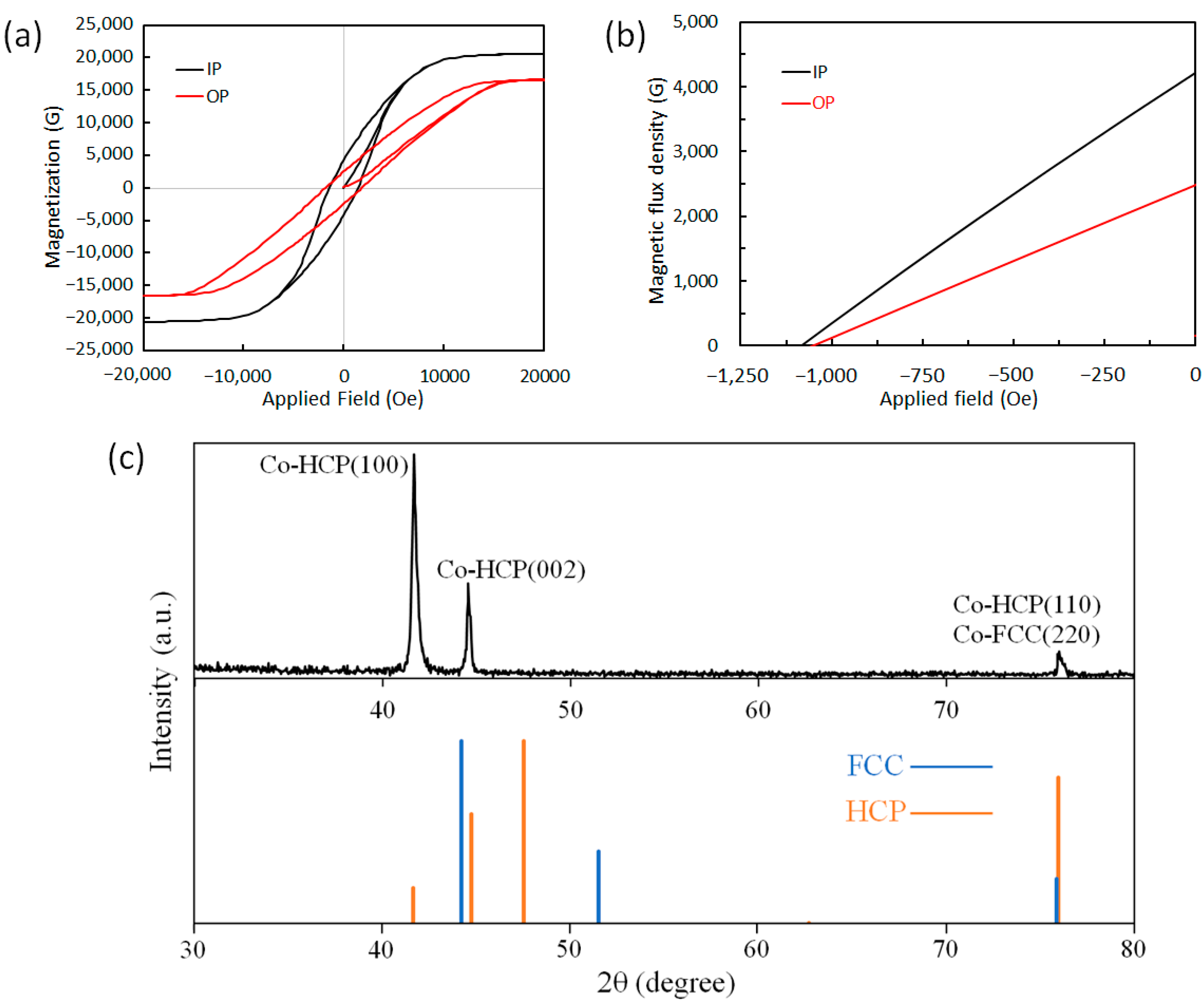
| Direction of Characterization | Hci (Oe) | Ms (G) | Hc (Oe) | Br (G) | (BH)max (MGOe) |
|---|---|---|---|---|---|
| In-plane | 1412 | 18,050 | 1083 | 4218 | 1.16 |
| Out-of-plane | 1803 | 14,550 | 1050 | 2482 | 0.65 |
Disclaimer/Publisher’s Note: The statements, opinions and data contained in all publications are solely those of the individual author(s) and contributor(s) and not of MDPI and/or the editor(s). MDPI and/or the editor(s) disclaim responsibility for any injury to people or property resulting from any ideas, methods, instructions or products referred to in the content. |
© 2023 by the authors. Licensee MDPI, Basel, Switzerland. This article is an open access article distributed under the terms and conditions of the Creative Commons Attribution (CC BY) license (https://creativecommons.org/licenses/by/4.0/).
Share and Cite
Kotnana, G.; Cheng, Y.; Lin, C.-C. Triggering Magnets for Wiegand Sensors: Electrodeposited and Origami-Magnetized CoNiP Micro-Magnets. Sensors 2023, 23, 6043. https://doi.org/10.3390/s23136043
Kotnana G, Cheng Y, Lin C-C. Triggering Magnets for Wiegand Sensors: Electrodeposited and Origami-Magnetized CoNiP Micro-Magnets. Sensors. 2023; 23(13):6043. https://doi.org/10.3390/s23136043
Chicago/Turabian StyleKotnana, Ganesh, Yun Cheng, and Chiao-Chi Lin. 2023. "Triggering Magnets for Wiegand Sensors: Electrodeposited and Origami-Magnetized CoNiP Micro-Magnets" Sensors 23, no. 13: 6043. https://doi.org/10.3390/s23136043
APA StyleKotnana, G., Cheng, Y., & Lin, C.-C. (2023). Triggering Magnets for Wiegand Sensors: Electrodeposited and Origami-Magnetized CoNiP Micro-Magnets. Sensors, 23(13), 6043. https://doi.org/10.3390/s23136043