


Design and Validation of a Low-Cost Mobile EEG-Based Brain–Computer Interface

 , , , , , , and
Abstract
1. Introduction
2. Methods
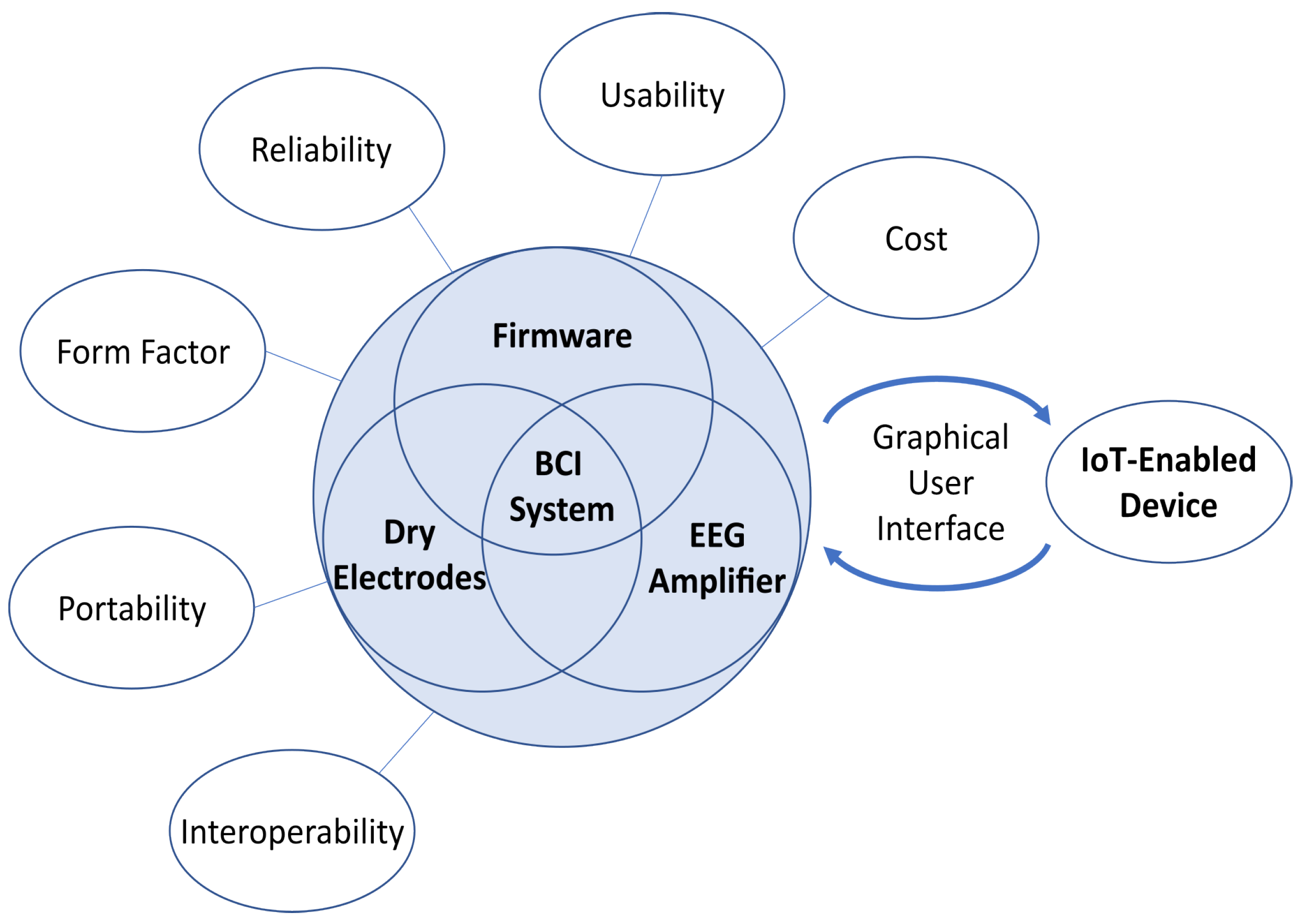
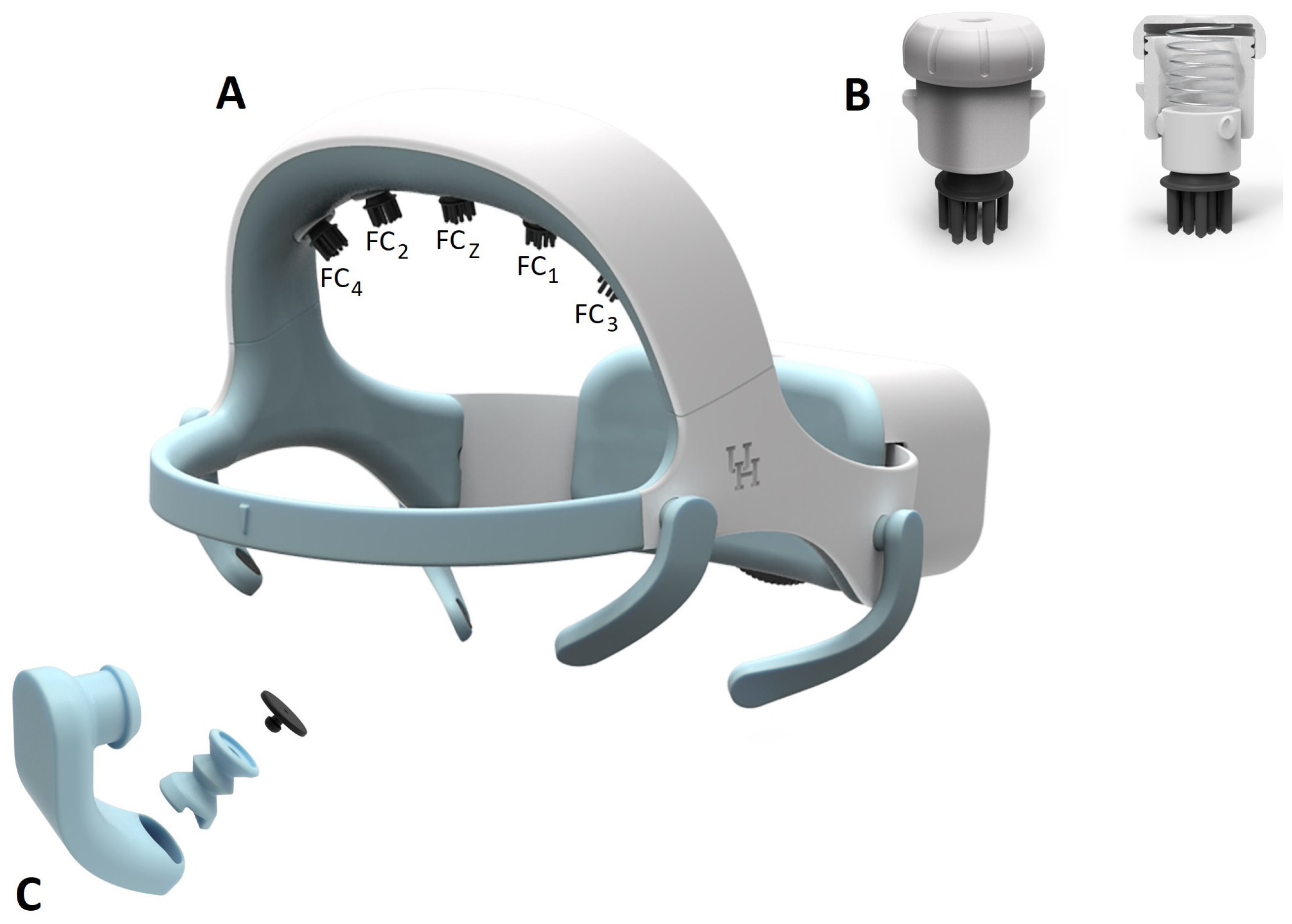
2.1. Headset Design
2.1.1. Electrodes
2.1.2. EEG Electrode-Holder Design
2.1.3. EOG Electrode-Holder Design
2.1.4. Headset Size and Adjustment Mechanism Design
2.1.5. Headset Fabrication
2.2. Design of the BCI Module
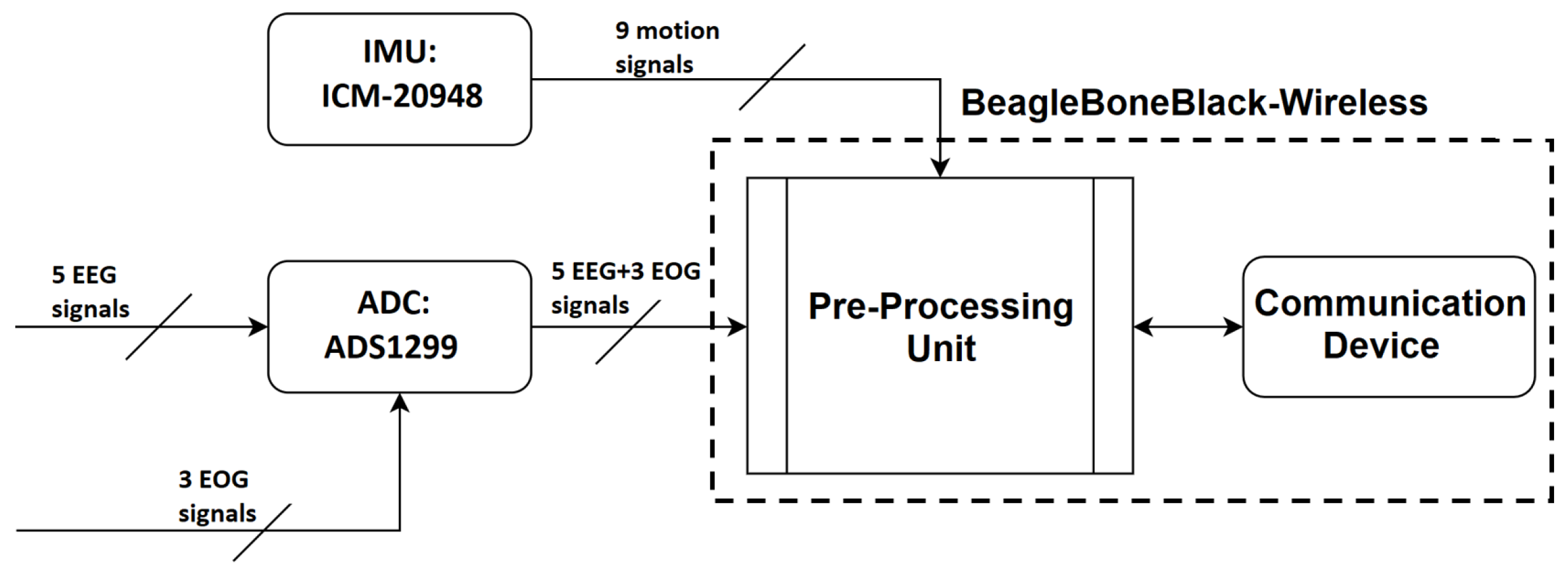
2.2.1. Hardware Selections and Development
Processor Selection
Design of the Integrated Amplifier and Processing Board
Power System
2.2.2. Software
Firmware
Communication
Open-Loop Capabilities
EEG De-Noising Capabilities
Closed-Loop Capabilities
Modular Software Design
2.3. System Validation
2.3.1. Headset Design Validation
2.3.2. Open-Loop Brain–Computer Interface Validation
2.3.3. Closed-Loop Brain–Computer Interface Validation
3. Results
3.1. Headset Design Validation Results
3.1.1. System Comfort Test
3.1.2. System Usability Test
3.2. Open-Loop BCI Validation
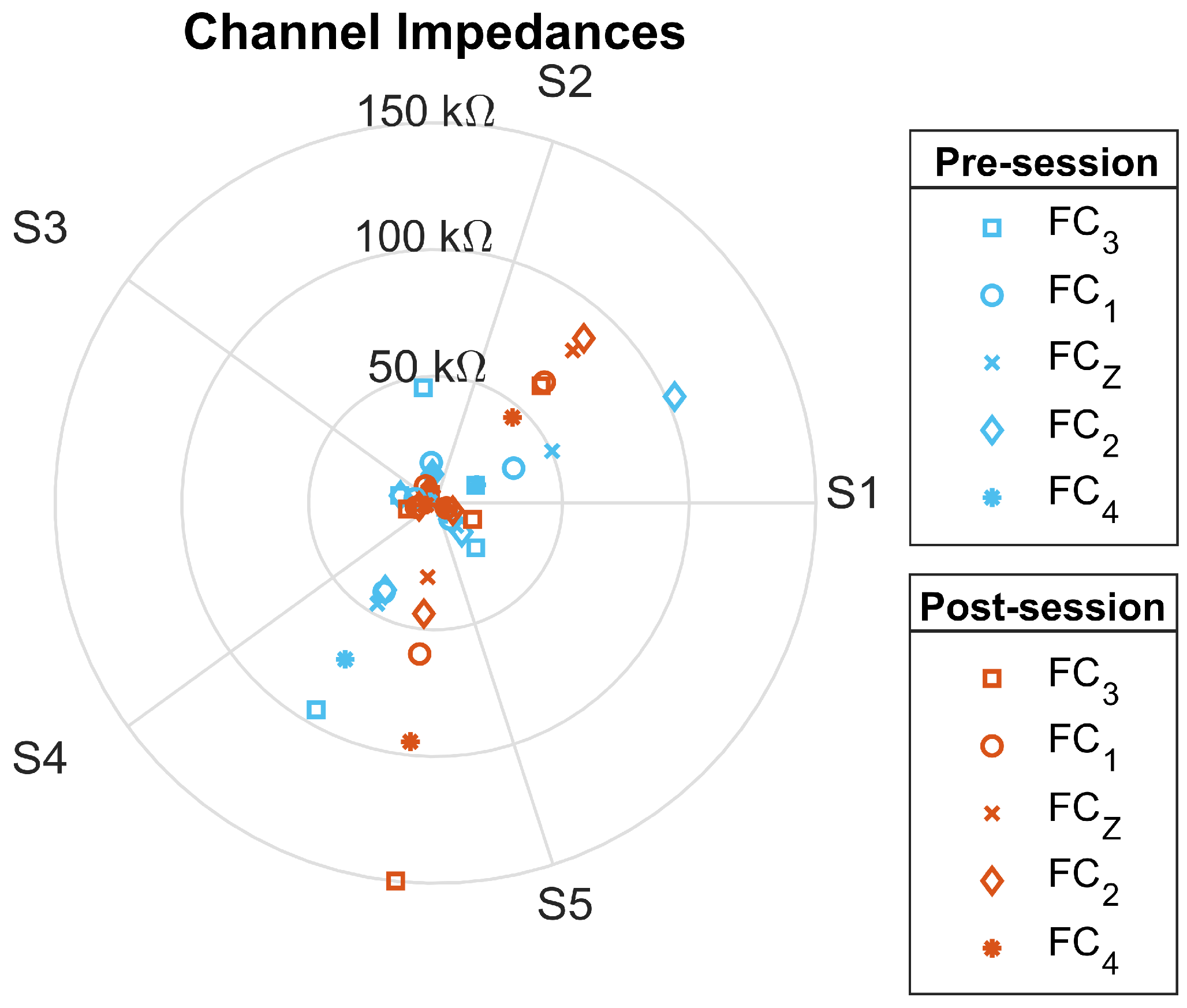
3.2.1. Signal-Quality Test
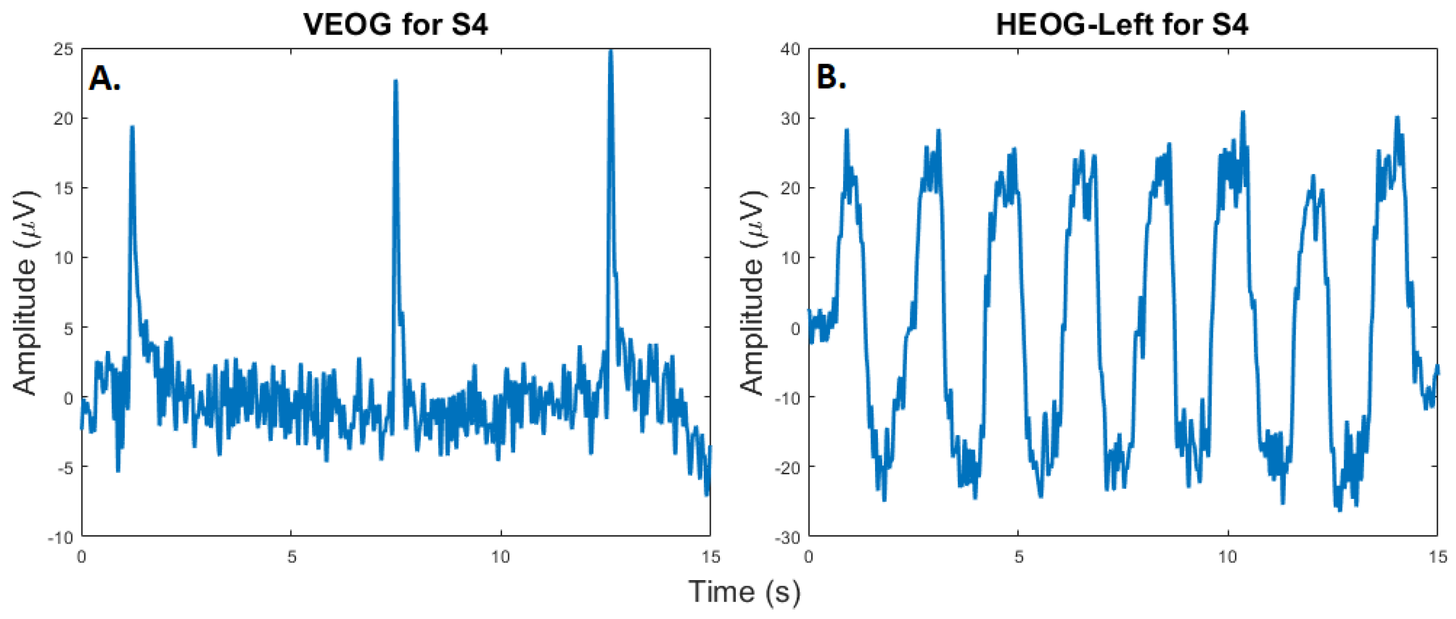
3.2.2. Eye-Tracking Test
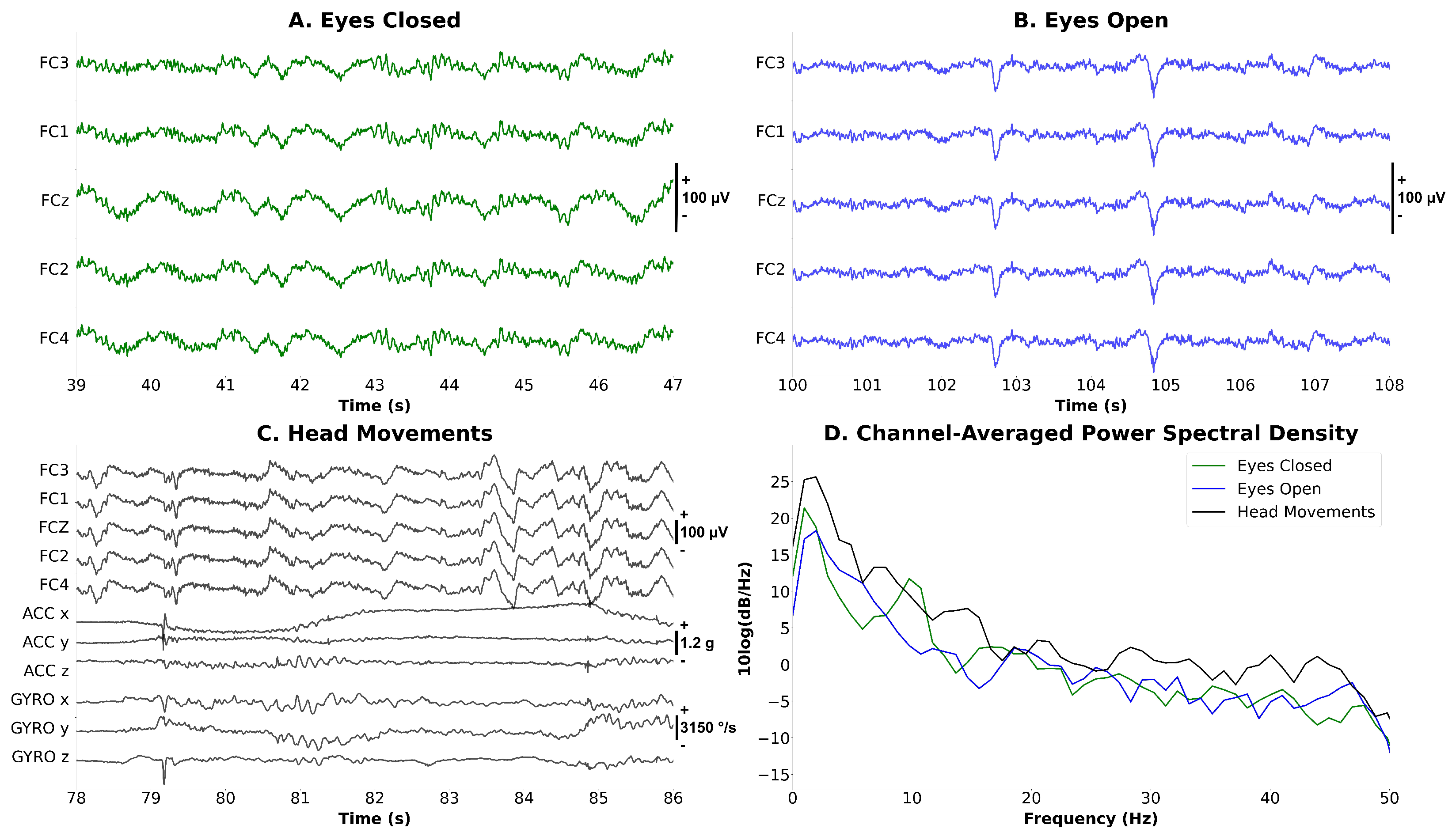
3.2.3. Synchronized EEG–EOG–IMU Test
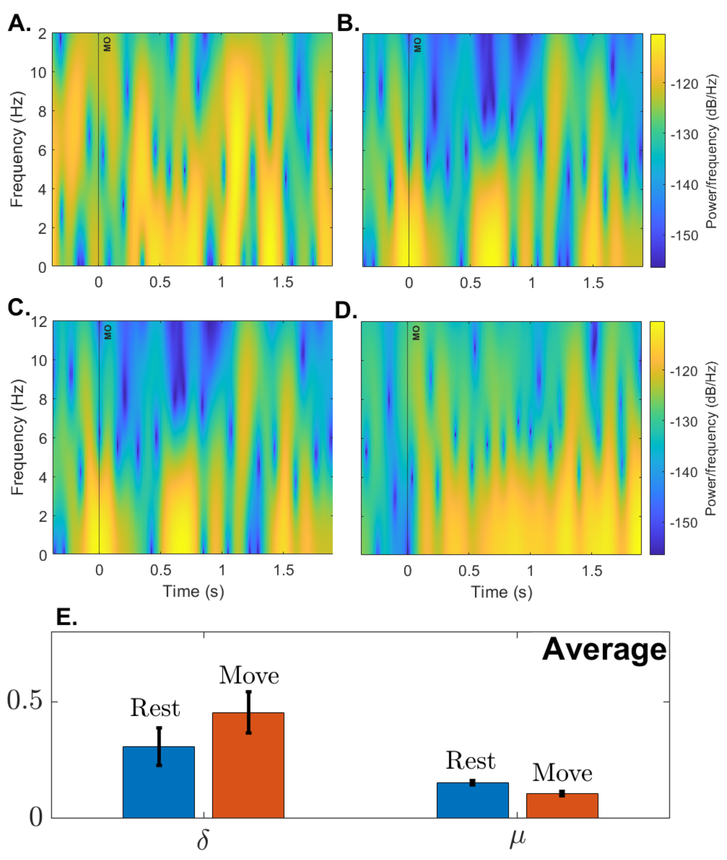
3.2.4. Open-Loop Performance
3.3. Closed-Loop BCI Validation
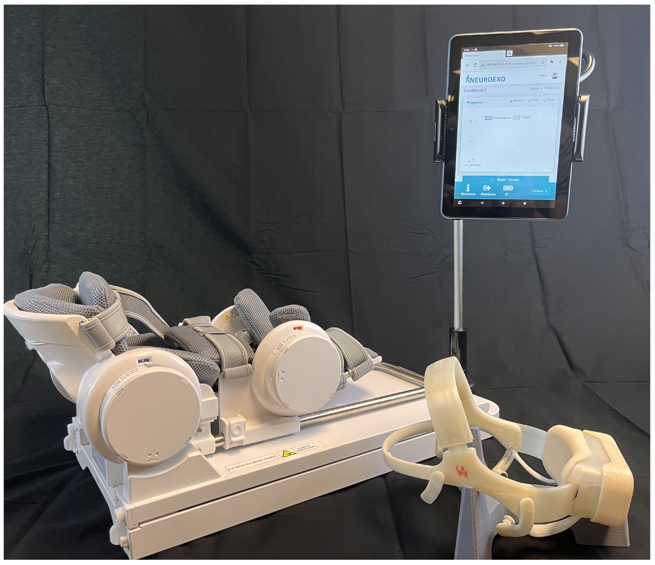
3.3.1. IoT Functionality Test
3.3.2. Support Vector Machine Model Training
3.3.3. Closed-Loop BCI Performance
4. Discussion and Conclusions
Author Contributions
Funding
Institutional Review Board Statement
Informed Consent Statement
Data Availability Statement
Acknowledgments
Conflicts of Interest
Appendix A
Appendix A.1. Inertial Measurement Unit Characteristics

| Metric | ICM-20948 |
|---|---|
| ADC (bits) | 16 |
| Dynamic Range (dps) | 250–2000 |
| Zero offset error (dps) (at 250 dps) | |
| Zero-g Offset (mg) | |
| Power Acc + Mgn (mW) | 0.58 |
| Power Gyro (mW) | 4.43 |
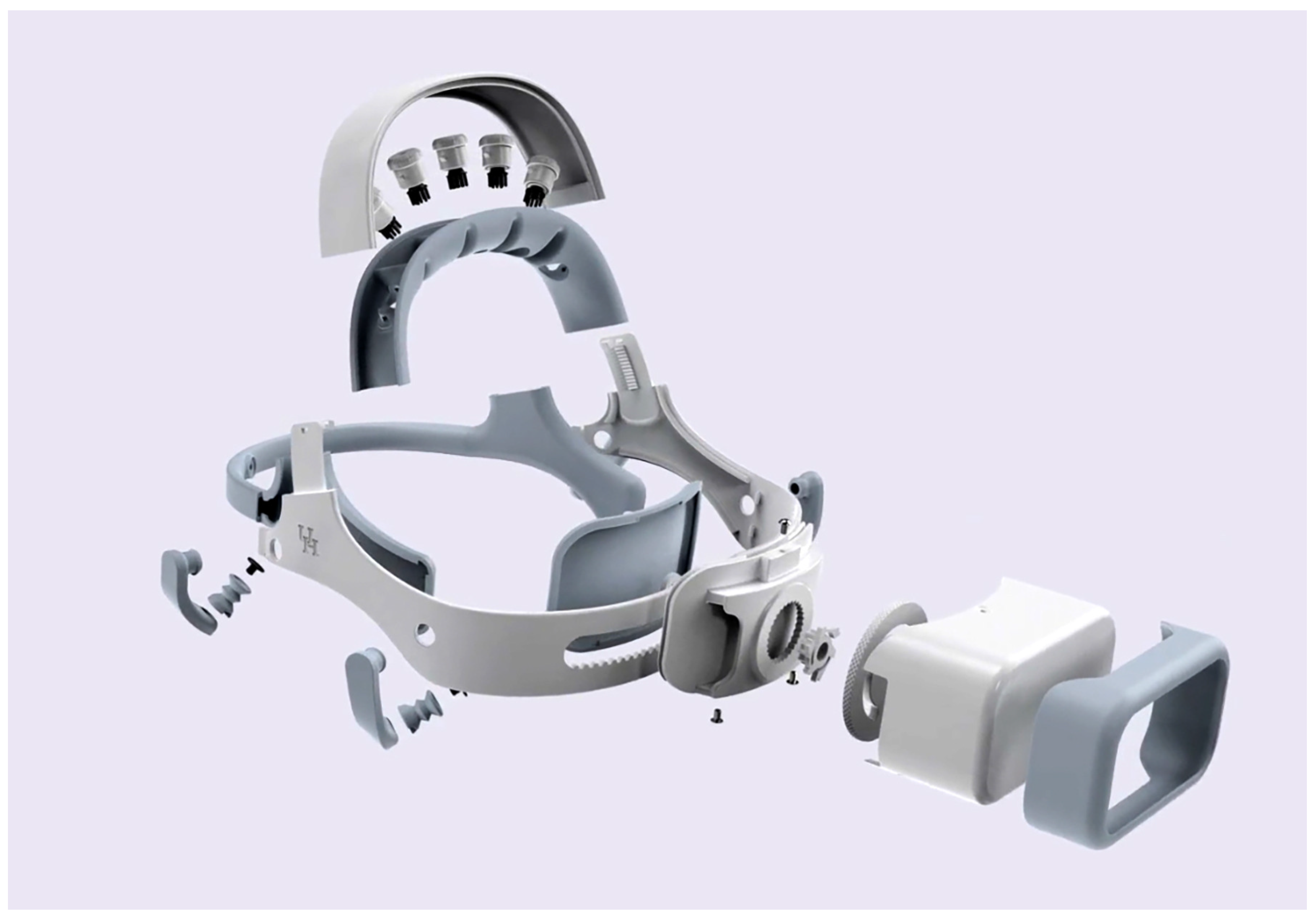
Appendix A.2. Exploded Headset Image

References
- Kübler, A. The history of BCI: From a vision for the future to real support for personhood in people with locked-in syndrome. Neuroethics 2020, 13, 163–180. [Google Scholar] [CrossRef]
- Nijholt, A.; Contreras-Vidal, J.; Jeunet, C.; Väljamäe, A. Brain-Computer Interfaces for Non-clinical (Home, Sports, Art, Entertainment, Education, Well-Being) Applications. Front. Comput. Sci. 2022, 4, 860619. [Google Scholar] [CrossRef]
- Urigüen, J.; Garcia-Zapirain, B. EEG artifact removal—State-of-the-art and guidelines. J. Neural Eng. 2015, 12, 031001. [Google Scholar] [CrossRef] [PubMed]
- Goldenholz, D.; Ahlfors, S.; Hämäläinen, M.; Sharon, D.; Ishitobi, M.; Vaina, L.; Stufflebeam, S. Mapping the signal-to-noise-ratios of cortical sources in magnetoencephalography and electroencephalography. Hum. Brain Mapp. 2009, 30, 1077–1086. [Google Scholar] [CrossRef]
- Kilicarslan, A.; Grossman, R.G.; Contreras-Vidal, J.L. A robust adaptive de-noising framework for real-time artifact removal in scalp eeg measurements. J. Neural Eng. 2016, 13, 026013. [Google Scholar] [CrossRef]
- Kilicarslan, A.; Vidal, J. Characterization and real-time removal of motion artifacts from EEG signals. J. Neural Eng. 2019, 16, 056027. [Google Scholar] [CrossRef] [PubMed]
- Craik, A.; He, Y.; Contreras-Vidal, J.L. Deep learning for electroencephalogram (eeg) classification tasks: A review. J. Neural Eng. 2019, 16, 031001. [Google Scholar] [CrossRef]
- Roy, Y.; Banville, H.; Albuquerque, I.; Gramfort, A.; Falk, T.; Faubert, J. Deep learning-based electroencephalography analysis: A systematic review. J. Neural Eng. 2019, 16, 051001. [Google Scholar] [CrossRef]
- Abiri, R.; Borhani, S.; Sellers, E.; Jiang, Y.; Zhao, X. A comprehensive review of EEG-based brain—Computer interface paradigms. J. Neural Eng. 2019, 16, 011001. [Google Scholar] [CrossRef]
- Steele, A.G.; Parekh, S.; Azgomi, H.F.; Ahmadi, M.B.; Craik, A.; Pati, S.; Francis, J.T.; Contreras-Vidal, J.L.; Faghih, R.T. A mixed filtering approach for real-time seizure state tracking using multi-channel electroencephalography data. IEEE Trans. Neural Syst. Rehabil. Eng. 2021, 29, 2037–2045. [Google Scholar] [CrossRef] [PubMed]
- Ahmadi, M.B.; Craik, A.; Azgomi, H.F.; Francis, J.T.; Contreras-Vidal, J.L.; Faghih, R.T. Real-time seizure state tracking using two channels: A mixed-filter approach. In Proceedings of the 2019 53rd Asilomar Conference on Signals, Systems, and Computers, Pacific Grove, CA, USA, 3–6 November 2019; pp. 2033–2039. [Google Scholar]
- Aboalayon, K.A.I.; Faezipour, M.; Almuhammadi, W.S.; Moslehpour, S. Sleep stage classification using eeg signal analysis: A comprehensive survey and new investigation. Entropy 2016, 18, 272. [Google Scholar] [CrossRef]
- Zhou, Y.; Huang, S.; Xu, Z.; Wang, P.; Wu, X.; Zhang, D. Cognitive workload recognition using eeg signals and machine learning: A review. IEEE Trans. Cogn. Dev. Syst. 2021, 14, 799–818. [Google Scholar] [CrossRef]
- Craik, A.; Kilicarslan, A.; Contreras-Vidal, J.L. Classification and transfer learning of eeg during a kinesthetic motor imagery task using deep convolutional neural networks. In Proceedings of the 2019 41st Annual International Conference of the IEEE Engineering in Medicine and Biology Society (EMBC), Berlin, Germany, 23–27 July 2019; pp. 3046–3049. [Google Scholar]
- Ferrero, L.; Quiles, V.; Ortiz, M.; Iáñez, E.; Navarro-Arcas, A.; Flores-Yepes, J.; Contreras-Vidal, J.; Azorín, J. Comparison of different brain–computer interfaces to assess motor imagery using a lower-limb exoskeleton. In Converging Clinical and Engineering Research on Neurorehabilitation IV, Proceedings of the 5th International Conference on Neurorehabilitation (ICNR2020), Online, 13–16 October 2020; Springer: Berlin/Heidelberg, Germany, 2022; pp. 53–58. [Google Scholar]
- Bundy, D.T.; Souders, L.; Baranyai, K.; Leonard, L.; Schalk, G.; Coker, R.; Moran, D.W.; Huskey, T.; Leuthardt, E.C. Contralesional brain—Computer interface control of a powered exoskeleton for motor recovery in chronic stroke survivors. Stroke 2017, 48, 1908–1915. [Google Scholar] [CrossRef]
- Bhagat, N.A.; Yozbatiran, N.; Sullivan, J.L.; Paranjape, R.; Losey, C.; Hernandez, Z.; Keser, Z.; Grossman, R.; Francisco, G.; O’Malley, M.K.; et al. A clinical trial to study changes in neural activity and motor recovery following brain-machine interface enabled robot-assisted stroke rehabilitation. medRxiv 2020. [Google Scholar] [CrossRef]
- Nijholt, A. Multi-modal and multi-brain-computer interfaces: A review. In Proceedings of the 2015 10th International Conference on Information, Communications and Signal Processing (ICICS), Singapore, 2–4 December 2015; pp. 1–5. [Google Scholar]
- Hekmatmanesh, A.; Nardelli, P.H.; Handroos, H. Review of the state-of-the-art of brain-controlled vehicles. IEEE Access 2021, 9, 110173–110193. [Google Scholar] [CrossRef]
- Shukla, P.K.; Chaurasiya, R.K. A review on classification methods used in eeg-based home control systems. In Proceedings of the 2018 3rd International Conference and Workshops on Recent Advances and Innovations in Engineering (ICRAIE), Jaipur, India, 22–25 November 2018; pp. 1–5. [Google Scholar]
- Zhang, R. Virtual reality games based on brain computer interface. In Proceedings of the 2020 International Conference on Intelligent Computing and Human-Computer Interaction (ICHCI), Sanya, China, 4–6 December 2020; pp. 227–230. [Google Scholar]
- Kerous, B.; Liarokapis, F. Brain-computer interfaces-a survey on interactive virtual environments. In Proceedings of the 2016 8th International Conference on Games and Virtual Worlds for Serious Applications (vs.-Games), Barcelona, Spain, 7–9 September 2016; pp. 1–4. [Google Scholar]
- Craik, A.; Kilicarslan, A.; Contreras-Vidal, J.L. A translational roadmap for a brain-machine-interface (bmi) system for rehabilitation. In Proceedings of the 2019 IEEE International Conference on Systems, Man and Cybernetics (SMC), Bari, Italy, 6–9 October 2019; pp. 3613–3618. [Google Scholar]
- Merchak, T.; Goldberg, I. Concept to Clinic: Commercializing Innovation (C3i) Program; The National Institute of Biomedical Imaging and Bioengineering (NIBIB): Bethesda, MD, USA, 2021. [Google Scholar]
- Paek, A.; Brantley, J.; Ravindran, A.; Nathan, K.; He, Y.; Eguren, D.; Cruz-Garza, J.; Nakagome, S.; Wickramasuriya, D.; Chang, J.; et al. A roadmap towards standards for neurally controlled end effectors. IEEE Open J. Eng. Med. Biol. 2021, 2, 84–90. [Google Scholar] [CrossRef]
- Bowsher, K.; Civillico, E.; Coburn, J.; Collinger, J.; Contreras-Vidal, J.; Denison, T.; Donoghue, J.; French, J.; Getzoff, N.; Hochberg, L.; et al. Others Brain–computer interface devices for patients with paralysis and amputation: A meeting report. J. Neural Eng. 2016, 13, 023001. [Google Scholar] [CrossRef]
- Mooney, J. Strategies for supporting application portability. Computer 1990, 23, 59–70. [Google Scholar] [CrossRef]
- Brooke, J. SUS-A Quick and Dirty Usability Scale. Usability Evaluation in Industry; CRC Press: Boca Raton, FL, USA, 1996; ISBN 9780748404605. Available online: https://www.crcpress.com (accessed on 15 October 2022).
- Bevana, N.; Kirakowskib, J.; Maissela, J. What is usability. In Proceedings of the 4th International Conference on HCI, Stuttgart, Germany, 1–6 September 1991; pp. 1–6. [Google Scholar]
- Stavrakos, S.; Ahmed-Kristensen, S. Assessment of anthropometric methods in headset design. In Proceedings of the DESIGN 2012, The 12th International Design Conference (DS 70), Dubrovnik, Croatia, 21–24 May 2012. [Google Scholar]
- Chabin, T.; Gabriel, D.; Haffen, E.; Moulin, T.; Pazart, L. Are the new mobile wireless EEG headsets reliable for the evaluation of musical pleasure? PLoS ONE 2020, 15, e0244820. [Google Scholar] [CrossRef]
- Jiang, X.; Bian, G.; Tian, Z. Removal of artifacts from EEG signals: A review. Sensors 2019, 19, 987. [Google Scholar] [CrossRef]
- He, Y.; Eguren, D.; Azorín, J.M.; Grossman, R.G.; Luu, T.P.; Contreras-Vidal, J.L. Brain–machine interfaces for controlling lower-limb powered robotic systems. J. Neural Eng. 2018, 15, 021004. [Google Scholar] [CrossRef] [PubMed]
- Open Source Tools for Neuroscience. Available online: https://openbci.com/ (accessed on 2 February 2023).
- Meditation Made Easy. 2023. Available online: https://choosemuse.com/ (accessed on 2 February 2023).
- Xing, X.; Wang, Y.; Pei, W.; Guo, X.; Liu, Z.; Wang, F.; Ming, G.; Zhao, H.; Gui, Q.; Chen, H. A high-speed SSVEP-based BCI using dry EEG electrodes. Sci. Rep. 2018, 8, 14708. [Google Scholar] [CrossRef] [PubMed]
- Arpaia, P.; Callegaro, L.; Cultrera, A.; Esposito, A.; Ortolano, M. Metrological characterization of consumer-grade equipment for wearable brain—Computer interfaces and extended reality. IEEE Trans. Instrum. Meas. 2021, 71, 4002209. [Google Scholar] [CrossRef]
- Fok, S.; Schwartz, R.; Wronkiewicz, M.; Holmes, C.; Zhang, J.; Somers, T.; Bundy, D.; Leuthardt, E. An EEG-based brain computer interface for rehabilitation and restoration of hand control following stroke using ipsilateral cortical physiology. In Proceedings of the 2011 Annual International Conference of The IEEE Engineering In Medicine And Biology Society, Boston, MA, USA, 30 August–3 September 2011; pp. 6277–6280. [Google Scholar]
- EMOTIV Emotiv EPOC X: 14 Channel Mobile EEG Headset. EMOTIV. 2023. Available online: https://www.emotiv.com/epoc-x/ (accessed on 2 February 2023).
- Schalk, G.; McFarl, D.; Hinterberger, T.; Birbaumer, N.; Wolpaw, J. BCI2000: A general-purpose brain-computer interface (BCI) system. IEEE Trans. Biomed. Eng. 2004, 51, 1034–1043. [Google Scholar] [CrossRef] [PubMed]
- Niso, G.; Romero, E.; Moreau, J.T.; Araujo, A.; Krol, L.R. Wireless eeg: An survey of systems and studies. NeuroImage 2022, 269, 119774. [Google Scholar] [CrossRef]
- ISO 9241-210:2010; Ergonomics of Human-System Interaction—Part 210: Human-Centred Design for Interactive Systems. ISO: Geneva, Switzerland, 2010.
- Feng, T.; Kuhn, D.; Ball, K.; Kerick, S.; McDowell, K. Evaluation of a Prototype Low-Cost, Modular, Wireless Electroencephalography (Eeg) Headset Design for Widespread Application; Army Research Lab.: Adelphi, MD, USA, 2016. [Google Scholar]
- Hairston, W.D.; Whitaker, K.W.; Ries, A.J.; Vettel, J.M.; Bradford, J.C.; Kerick, S.E.; McDowell, K. Usability of four commercially-oriented eeg systems. J. Neural Eng. 2014, 11, 046018. [Google Scholar] [CrossRef]
- Verwulgen, S.; Lacko, D.; Vleugels, J.; Vaes, K.; Danckaers, F.; Bruyne, G.D.; Huysmans, T. A new data structure and workflow for using 3d anthropometry in the design of wearable products. Int. J. Ind. Ergon. 2018, 64, 108–117. [Google Scholar] [CrossRef]
- Li, G.; Wang, S.; Duan, Y.Y. Towards gel-free electrodes: A systematic study of electrode-skin impedance. Sens. Actuators Chem. 2017, 241, 1244–1255. [Google Scholar] [CrossRef]
- Pheasant, S.; Haslegrave, C.M. Bodyspace: Anthropometry, Ergonomics and the Design of Work; CRC Press: Boca Raton, FL, USA, 2018. [Google Scholar]
- Lacko, D.; Vleugels, J.; Fransen, E.; Huysmans, T.; Bruyne, G.D.; Hulle, M.M.V.; Sijbers, J.; Verwulgen, S. Ergonomic design of an eeg headset using 3d anthropometry. Appl. Ergon. 2017, 58, 128–136. [Google Scholar] [CrossRef]
- Ellena, T.; Subic, A.; Mustafa, H.; Pang, T.Y. The helmet fit index—An intelligent tool for fit assessment and design customisation. Appl. Ergon. 2016, 55, 194–207. [Google Scholar] [CrossRef]
- Karlson, A.K.; Bederson, B.B.; Contreras-Vidal, J. Understanding single-handed mobile device interaction. Handb. Res. User Interface Des. Eval. Mob. Technol. 2006, 1, 86–101. [Google Scholar]
- Yates, D.C.; Rodriguez-Villegas, E. A key power trade-off in wireless eeg headset design. In Proceedings of the 2007 3rd International IEEE/EMBS Conference on Neural Engineering, Kohala Coast, HI, USA, 2–5 May 2007; pp. 453–456. [Google Scholar]
- Acharya, J.N.; Hani, A.J.; Thirumala, P.; Tsuchida, T.N. American clinical neurophysiology society guideline 3: A proposal for standard montages to be used in clinical eeg. Neurodiagn. J. 2016, 56, 253–260. [Google Scholar] [CrossRef] [PubMed]
- Wang, D.; Miao, D.; Blohm, G. Multi-class motor imagery EEG decoding for brain-computer interfaces. Front. Neurosci. 2012, 6, 151. [Google Scholar] [CrossRef] [PubMed]
- Chen, Y.-H.; de Beeck, M.O.; Vanderheyden, L.; Mihajlovic, V.; Grundlehner, B.; Hoof, C.V. Comb-shaped polymer-based dry electrodes for eeg/ecg measurements with high user comfort. In Proceedings of the 2013 35th Annual International Conference of the IEEE Engineering in Medicine and Biology Society (EMBC), Osaka, Japan, 3–7 July 2013; pp. 551–554. [Google Scholar]
- Kawana, T.; Yoshida, Y.; Kudo, Y.; Iwatani, C.; Miki, N. Design and characterization of an eeg-hat for reliable eeg measurements. Micromachines 2020, 11, 635. [Google Scholar] [CrossRef] [PubMed]
- Gorman, N.; Louw, A.; Craik, A.; Gonzalez, J.; Feng, J.; Contreras-Vidal, J.L. Design principles for mobile brain-body imaging devices with optimized ergonomics. In Proceedings of the International Conference on Applied Human Factors and Ergonomics, Virtually, 25–29 July 2021; Springer: Berlin/Heidelberg, Germany, 2021; pp. 3–10. [Google Scholar]
- Gordon, C.C.; Blackwell, C.L.; Bradtmiller, B.; Parham, J.L.; Barrientos, P.; Paquette, S.P.; Corner, B.D.; Carson, J.M.; Venezia, J.C.; Rockwell, B.M.; et al. 2012 Anthropometric Survey of US Army Personnel: Methods and Summary Statistics; Army Natick Soldier Research Development and Engineering Center: Natick, MA, USA, 2014. [Google Scholar]
- Meet Beagle™: Open Source Computing. Available online: https://beagleboard.org/ (accessed on 2 February 2023).
- Linx Labview Makerhub. Available online: https://www.labviewmakerhub.com/doku.php?id=learn:start (accessed on 2 February 2023).
- Nuwer, M.; Comi, G.; Emerson, R.; Fuglsang-Frederiksen, A.; Guerit, J.; Hinrichs, H.; Ikeda, A.; Luccas, F.; Rappelsburger, P. IFCN standards for digital recording of clinical EEG. Electroencephalogr. Clin. Neurophysiol. 1998, 106, 259–261. [Google Scholar] [CrossRef] [PubMed]
- Texas Instruments. ADS1299 Analog-to-Digital Converter for EEG and Biopotential Measurements; Texas Instruments: Dallas, TX, USA, 2017. [Google Scholar]
- TDK. ICM-20948 World’s Lowest Power 9-Axis MEMS MotionTracking™ Device; TDK InvenSense: San Jose, CA, USA, 2021. [Google Scholar]
- Louis. Polymer Lithium-ion Battery Product Specification; AA Portable Power Corp: Richmond, CA, USA, 2010. [Google Scholar]
- Octavo Systems LLC. OSD3358 Application Guide; Octavo Systems LLC: Austin, TX, USA, 2017. [Google Scholar]
- Jenny, B.; Kelso, N.V. Color design for the color vision impaired. Cartogr. Perspect. 2007, 61–67. [Google Scholar] [CrossRef]
- Allan, J. Accessibility Requirements for People with Low Vision. 2016. Available online: https://www.w3.org/TR/low-vision-needs/ (accessed on 2 February 2023).
- Zander, T.O.; Andreessen, L.M.; Berg, A.; Bleuel, M.; Pawlitzki, J.; Zawallich, L.; Krol, L.R.; Gramann, K. Evaluation of a dry eeg system for application of passive brain-computer interfaces in autonomous driving. Front. Hum. Neurosci. 2017, 11, 78. [Google Scholar] [CrossRef]
- Bangor, A.; Kortum, P.; Miller, J. Determining what individual SUS scores mean: Adding an adjective rating scale. J. Usability Stud. 2009, 4, 114–123. [Google Scholar]
- Hallett, M. Movement-related cortical potentials. Electromyogr. Clin. Neurophysiol. 1994, 34, 5–13. [Google Scholar]
- Lu, M.; Arai, N.; Tsai, C.; Ziemann, U. Movement related cortical potentials of cued versus self-initiated movements: Double dissociated modulation by dorsal premotor cortex versus supplementary motor area rTMS. Hum. Brain Mapp. 2012, 33, 824–839. [Google Scholar] [CrossRef]
- Niazi, I.; Jiang, N.; Tiberghien, O.; Nielsen, J.; Dremstrup, K.; Farina, D. Detection of movement intention from single-trial movement-related cortical potentials. J. Neural Eng. 2011, 8, 066009. [Google Scholar] [CrossRef] [PubMed]
- Siemionow, V.; Yue, G.; Ranganathan, V.; Liu, J.; Sahgal, V. Relationship between motor activity-related cortical potential and voluntary muscle activation. Exp. Brain Res. 2000, 133, 303–311. [Google Scholar] [CrossRef] [PubMed]
- Shibasaki, H.; Barrett, G.; Halliday, E.; Halliday, A. Components of the movement-related cortical potential and their scalp topography. Electroencephalogr. Clin. Neurophysiol. 1980, 49, 213–226. [Google Scholar] [CrossRef] [PubMed]
- Shakeel, A.; Navid, M.; Anwar, M.; Mazhar, S.; Jochumsen, M.; Niazi, I. A review of techniques for detection of movement intention using movement-related cortical potentials. Comput. Math. Methods Med. 2015, 2015, 346217. [Google Scholar] [CrossRef]
- Duvinage, M.; Castermans, T.; Petieau, M.; Seetharaman, K.; Hoellinger, T.; Cheron, G.; Dutoit, T. A subjective assessment of a p300 bci system for lower-limb rehabilitation purposes. In Proceedings of the 2012 Annual International Conference of the IEEE Engineering in Medicine and Biology Society, San Diego, CA, USA, 28 August–1 September 2012; pp. 3845–3849. [Google Scholar]
- Goncharova, I.; McFarl, D.; Vaughan, T.; Wolpaw, J. EMG contamination of EEG: Spectral and topographical characteristics. Clin. Neurophysiol. 2003, 114, 1580–1593. [Google Scholar] [CrossRef]
- Barry, R.; Clarke, A.; Johnstone, S.; Magee, C.; Rushby, J. EEG differences between eyes-closed and eyes-open resting conditions. Clin. Neurophysiol. 2007, 118, 2765–2773. [Google Scholar] [CrossRef]
- Kuhlman, W.N. Functional topography of the human mu rhythm. Electroencephalogr. Clin. Neurophysiol. 1978, 44, 83–93. [Google Scholar] [CrossRef]
- Müller, V.; Anokhin, A.P. Neural synchrony during response production and inhibition. PLoS ONE 2012, 7, e38931. [Google Scholar] [CrossRef]
- Schoppenhorst, M.; Brauer, F.; Freund, G.; Kubicki, S. The significance of coherence estimates in determining central alpha and mu activities. Electroencephalogr. Clin. Neurophysiol. 1980, 48, 25–33. [Google Scholar] [CrossRef]
- Bhagat, N.A.; Venkatakrishnan, A.; Abibullaev, B.; Artz, E.J.; Yozbatiran, N.; Blank, A.A.; French, J.; Karmonik, C.; Grossman, R.G.; O’Malley, M.K.; et al. Design and optimization of an eeg-based brain machine interface (bmi) to an upper-limb exoskeleton for stroke survivors. Front. Neurosci. 2016, 10, 122. [Google Scholar] [CrossRef]


| Headset Specifications | |
| Circumference Adjustment Range (cm) | 52.3–61.2 |
| Head Breadth Adjustment Range (cm) | 13.8–16.6 |
| Head Length Adjustment Range (cm) | 17.3–21.4 |
| Electroencephalography (EEG) Electrode Locations | Frontocentral (FC) 3, FC1, FCz, FC2, FC4 |
| EEG Electrode Type | Dry Comb Electrodes |
| Electrooculography (EOG) Electrode Locations | Both Temples, Above Left Eye |
| Reference Electrode Locations | Mastoids |
| EOG and Reference Electrode Type | Dry Flat Electrodes |
| Amplifier Specifications | |
| Number of Channels | 8 |
| Signal–to–Noise Ratio (SNR) (dB) | 121 |
| Input Noise () | 1.39 |
| Common–Mode Rejection Ratio (CMRR) (dB) | 110 |
| Analog–to–Digital Converter (ADC) Resolution (bits) | 24 |
| Impedance (M) | 1000 |
| Maximum Sampling Rate (Hz) | 500 |
| Bandwidth (Hz) | DC-131 |
| Input range (mV) | ±104 |
| Resolution (V) | 0.012 |
| Inertial Measurement Unit Specifications | |
| ADC | 16 |
| Gyro Full-Scale Range (dps) | 250–2000 |
| Acc Full-Scale Range (g) | 2–16 |
| Zero offset error (for 250 dps) | 5 |
| Zero-g Offset (mg) | ±50 |
| Power Consumption Acc+Mgn (mW) | 0.58 |
| Power Consumption Gyro (mW) | 4.43 |
| Brain–Computer Interface Specifications | |
| Processor Speed (GHz) | 1 |
| Processor Memory (MB) | 512 |
| Processor Storage (GB) | 4 |
| Open-Loop Sampling Frequency (Hz) | 80 |
| Closed-Loop Sampling Frequency (Hz) | 40 |
| Communication | 802.11 b/g/n WiFi |
| Backend Coding Language | LabVIEW |
| Frontend Coding Language | JavaScript (JS), Cascading Style Sheets (CSS), HyperText Markup Language (HTML) |
| Machine Learning Capability | Support Vector Machine |
| De-noising Capabilities | Low- and High-Pass Filters; Adaptive Noise Cancellation |
| Battery Capacity (kWh) | 2.96 |
| Headset Design Validation | ||
|---|---|---|
| Test Name | Description | Assessment Tool/Specifications |
| System Comfort | Evaluation of user’s comfort level | Questionnaire/Likert scale |
| System Usability | System Usability Scale (SUS) [28] | SUS > 65 [67] |
| Open-Loop BCI Validation | ||
| Test Name | Description | Target Specifications |
| Signal Quality | Assessment of electrode and skin sensor impedance | Impedance < 100 kOhm |
| Eye Tracking | EOG evaluation | Detection of eye blinks and eye movements |
| Synchronized EEG-EOG-IMU | Acquire multi-modality data streams to confirm synchronized streaming of data | Synchronized EEG-EOG-IMU recordings ≤ 4 ms |
| Open-loop BCI Performance | Assessment of EEG power modulations in delta and mu bands during a GO-NOGO task | Event-related desynchronization/synchronization (ERD/ERS) |
| Closed-Loop Brain–Computer Interface Validation | ||
| Test Name | Description | Target Specifications |
| IoT Functionality | Assess communication rates between the headset and multiple types of devices | Communication rate < 50 ms for all connected devices |
| SVM Model Training | Evaluation of decoding accuracy for motor intent | Model accuracy ≥ 80%; detection of MRCPs |
| Closed-loop Performance | Evaluation of trained SVM for online prediction of motor intent | ≤50 ms closed-loop performance |
| Participant # | “Moving” | “Dents” | “Too Big” | “Too Small” |
|---|---|---|---|---|
| S1 | 5 | 5 | 5 | 5 |
| S2 | 5 | 2 | 5 | 5 |
| S3 | 4 | 2 | 3 | 3 |
| S4 | 4 | 2 | 5 | 5 |
| S5 | 5 | 3 | 5 | 5 |
| Mean | 4.6 | 2.8 | 4.6 | 4.6 |
| SD | 0.548 | 1.304 | 0.894 | 0.894 |
| Hyperparameter Optimization | ||
|---|---|---|
| Rejection Rate | Channels Not Used | Accuracy |
| 0 | - | 85.5% |
| 0.1 | - | 97.4% |
| 0.323 | - | 100.0% |
| 0.3 | - | 100.0% |
| 0 | FC3 | 96.3% |
| 0.1 | FC3 | 98.6% |
| 0.2 | FC3 | 99.3% |
| 0.3 | FC3 | 99.1% |
Disclaimer/Publisher’s Note: The statements, opinions and data contained in all publications are solely those of the individual author(s) and contributor(s) and not of MDPI and/or the editor(s). MDPI and/or the editor(s) disclaim responsibility for any injury to people or property resulting from any ideas, methods, instructions or products referred to in the content. |
© 2023 by the authors. Licensee MDPI, Basel, Switzerland. This article is an open access article distributed under the terms and conditions of the Creative Commons Attribution (CC BY) license (https://creativecommons.org/licenses/by/4.0/).
Share and Cite
Craik, A.; González-España, J.J.; Alamir, A.; Edquilang, D.; Wong, S.; Sánchez Rodríguez, L.; Feng, J.; Francisco, G.E.; Contreras-Vidal, J.L. Design and Validation of a Low-Cost Mobile EEG-Based Brain–Computer Interface. Sensors 2023, 23, 5930. https://doi.org/10.3390/s23135930
Craik A, González-España JJ, Alamir A, Edquilang D, Wong S, Sánchez Rodríguez L, Feng J, Francisco GE, Contreras-Vidal JL. Design and Validation of a Low-Cost Mobile EEG-Based Brain–Computer Interface. Sensors. 2023; 23(13):5930. https://doi.org/10.3390/s23135930
Chicago/Turabian StyleCraik, Alexander, Juan José González-España, Ayman Alamir, David Edquilang, Sarah Wong, Lianne Sánchez Rodríguez, Jeff Feng, Gerard E. Francisco, and Jose L. Contreras-Vidal. 2023. "Design and Validation of a Low-Cost Mobile EEG-Based Brain–Computer Interface" Sensors 23, no. 13: 5930. https://doi.org/10.3390/s23135930
APA StyleCraik, A., González-España, J. J., Alamir, A., Edquilang, D., Wong, S., Sánchez Rodríguez, L., Feng, J., Francisco, G. E., & Contreras-Vidal, J. L. (2023). Design and Validation of a Low-Cost Mobile EEG-Based Brain–Computer Interface. Sensors, 23(13), 5930. https://doi.org/10.3390/s23135930