Abstract
Unsourced multiple access (UMA) is the technology for massive, low-power, and uncoordinated Internet-of-Things in the 6G wireless system, improving connectivity and energy efficiency on guaranteed reliability. The multi-user coding scheme design is a critical problem for UMA. This paper proposes a UMA coding scheme based on the T-Fold IRSA (irregular repetition slotted Aloha) paradigm by using joint Intra/inter-slot code design and optimization. Our scheme adopts interleave-division multiple access (IDMA) to enhance the intra-slot coding gain and the low-complexity joint intra/inter-slot SIC (successive interference cancellation) decoder structure to recover multi-user payloads. Based on the error event decomposition and density evolution analysis, we build a joint intra/inter-slot coding parameter optimization algorithm to minimize the SNR (signal-to-noise ratio) requirement at an expected system packet loss rate. Numerical results indicate that the proposed scheme achieves energy efficiency gain by balancing the intra/inter-slot coding gain while maintaining relatively low implementation complexity.
1. Introduction
1.1. Background
Recently, academics and industry have proposed many prospects for the evolution of the IoT (Internet-of-Things) in the next generation [1]. In general, the 6G IoT system mainly faces the following three challenges: The rapid growth of connectivity [2], the guarantee of low latency under specific reliability [3], and the requirement of low power consumption and low implementation complexity [4].
Based on this, Polyanskiy proposed the concept of unsourced multiple access (UMA) in 2017 [5]. The UMA removes the coordination center in the network to reduce the transmission cost and latency of the frequent access of vast short packages, which is the major drawback of traditional schemes OMA (Orthogonal Multiple Access) [6], coordinated NOMA (Non-Orthogonal Multiple Access) [7], and grant-free access [8]. The uplink channel is always available to users, and the network works in the unsourced style, adapting to large-scale frequent connection requests. As a result, the system optimization criteria need to be changed from sum-rate to PUPE (Per-User Probability of Error), that is, to achieve the massive access ability under a specific average packet loss rate. The UMA’s achievability bound was given in [5], laying the foundation for research in this field.
1.2. Related Works
After that, many works emerged, exploring how to approach the performance bound through practical coding design under UMA [9,10]. These schemes are based on three basic paradigms: random spreading, T-Fold Aloha [11], and T-Fold IRSA (Irregular Repeated Slotted Aloha) [12].
The random spreading scheme regards the entire transmission frame as the available length of code chips for each user. The users’ data packets are superimposed after the symbol-level spreading. Representative works are the sparse IDMA (Interleave-Division Multiple Access) [13] based on LDPC (Low-Density Parity Check Code) and Polar-RS (Random Spreading) [14] and Polar-SS (Sparse Spreading) [15] based on polar codes. As such schemes occupy the entire frame to form a low-rate code, thereby obtaining the highest coding gain, which has a similar performance to that close to the boundary. However, at the same time, their high implementation complexity is also a problem that cannot be ignored.
T-Fold Aloha divides the transmission frame into slots with equal lengths. On each slot, a multi-access code is designed to control the error rate under multi-user superposition, ensuring a decodable threshold up to T. A classical realization is the concatenated code scheme [16], where the outer code guarantees the T-Fold feature, and the inner code treats noise. The compressed sensing (CS) encoder in CCS (Coded Compressed Sensing) [17] and SPARC (SParse Regression Code) [18] schemes plays the above two roles at the same time and has higher coding efficiency. However, the tree code also suffers an error propagation effect, and the CS coding gain is still limited in the region of high users.
T-Fold IRSA paradigm originated from the research on contention resolution Aloha [19] by G. Liva. Its design consists of two main aspects: the T-Fold intra-slot code and the packet-level inter-slot code. Cheng et al. proposed the SC-LDPC+IRSA scheme [20], spreading the SC-LDPC (Spatially Coupled-LDPC) packets by IRSA. Polar-IRSA [21] changed the SC-LDPC to the SCL decoded multi-user polar code with better performance under the short code length and achieved higher performance gain. In addition, [22] also gives a theoretical analysis of the IRSA framework based on the finite block length bound [23] and asymptotic analysis. Such schemes have performance advantages over T-Fold Aloha; under certain conditions, their performance is close to the high-complexity random spreading schemes. However, these schemes are based on the idealized asymptotic assumptions, the exploitation of intra-slot coding gain is limited, and there is still some room compared with the achievability bound.
In addition, some works also discuss the theoretical analysis [24] and coding scheme [25] design transferred from the AWGN channel to the Rayleigh block fading channel. Besides, MIMO (Multi-Input Multi-Output) transmission [26], channel estimation, activity detection [27], and their co-design [28] push the horizon from theory to practical deployment.
1.3. Contributions
Following the works under the T-Fold IRSA paradigm, we continue to investigate the trade-off between the intra-slot coding gain and the inter-slot diversity gain. Besides, with the premise of realization, we attempt to obtain improvement or balance in terms of performance and complexity. The main contributions of the proposed scheme are the following aspects:
- Enhanced intra-slot coding structure. We apply the IDMA scheme with CS header to intra-slot code design. The user payload is split into two parts, encoded by IDMA and CS encoders separately, and combined as the intra-slot codeword. The CS part carries the user-specific interleaver pattern of the IDMA codeword, and the IDMA part is the multi-access code resolving the superposition interference.
- Joint intra/inter-slot iterative decoder. Under the IRSA paradigm, the superimposed spreading pattern of intra-slot code packets is expanded as a compound inter-slot factor graph, recovered by combining the CS pilot decoding results among the slots. The ESE + BP decoder of the intra-slot IDMA code is the embedded operation on the slot nodes. The inter-slot SIC iteration is performed on the graph to eliminate the interference on the slot nodes, making the overload slot nodes decodable.
- Joint intra/inter-slot coding parameter optimization. To minimize the required SNR under the given PUPE standard and a limited number of channel resources, we follow the idea of error event decomposition to build the framework of parameter optimization. The error caused by each coding module is modeled as a function of its coding parameter. Especially, the inter-slot degree distribution is analyzed by density evolution with finite-length realization and energy cost conditions. Then we integrate these error functions in a global optimization problem and design a heuristic bootstrap search algorithm to jointly optimize all these related parameters, including the intra-slot CS pilot length, the IDMA coding rate, and the inter-slot degree distribution.
1.4. Content Organization
This article organizes its content in the following way. Section 2 gives some basic concepts and universal notations to help clarify the whole framework. Section 3 focuses on the encoder’s design and the proposed scheme’s decoding algorithm. Next, Section 4 discusses the coding parameter optimization problem based on error analysis by decomposition and the unified joint optimization algorithm. Finally, by numerical simulation, Section 5 evaluates its energy efficiency and computational complexity under the optimized configuration.
2. Definitions and Notations
The core problem of UMA is to construct a coding scheme that allows unsourced active users to transmit length-B data payload for each on a fixed length- frame at a target PUPE and given SNR level. By definition [5], the PUPE can be expressed as:
where k is the index of users and is the decoded version of transmitted payload . When , , and B are given, for each , there exists an optimal configuration for a coding scheme that makes the required SNR minimum, which is referred to as the SNR threshold. Thus, the energy efficiency of any UMA scheme can be characterized by the -SNR threshold curve.
Under the T-Fold IRSA paradigm, the entire frame of length is sliced into V slots with length for each. The degree distribution determines the distribution of the repetition rate of the intra-slot coded packets for each user. Since the packets are randomly distributed on slots, the number of superimposed packets on slot v is also randomized. The multi-user interference increases with . T-Fold means that the intra-slot code guarantees that at most users can be correctly decoded. Thus, is the threshold for the T-Fold IRSA system.
Here are some notations for matrices and vectors. The upper-bold case represents the matrix, and represents its element at the i-th row and the j-th column. The lower-bold case represents the vector, and is the i-th element. The vectors are column vectors in default.
3. Joint Intra/Inter-Slot Coding Scheme
The structure of the proposed coding scheme is given in this section. In general, it is an intra/inter-slot nested structure, as Figure 1 shows.
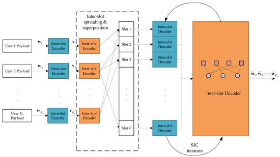
Figure 1.
The overall system framework of the proposed scheme.
The payload of each user is encoded by the intra-slot code to produce , and then randomly repeated times to form an inter-slot packet-level spreading pattern. On the receiver side, the slot-by-slot intra-slot decoding is integrated into the packet-level SIC iteration process on the inter-slot factor graph. The intra-slot codeword contains the IDMA codeword with a CS pilot indicating both the intra-slot interleaving pattern and the inter-slot spreading pattern. The inter-slot code is an IRSA structure enabling the SIC. Thus, the proposed scheme is introduced under the above framework.
3.1. Encoder
The intra-slot encoder is concatenated with the inter-slot encoder. The overall scheme of the encoder is depicted in Figure 2a. For each user k, the intra-slot coded packets are the non-zero ’chips’ of the inter-slot code. The intra-slot codeword consists of the CS pilot and the IDMA-coded part, each carrying part of the payload. Due to the unsourced feature, users must adopt a common codebook. Therefore, the CS pilot not only determines the user-specific configuration of the intra-slot code but also represents the structure of the inter-slot code, which are both randomized to deal with the multi-user interference.
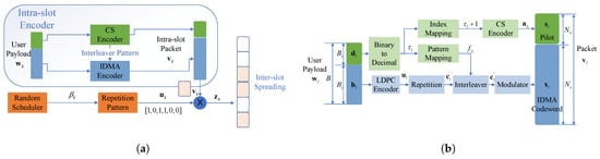
Figure 2.
(a) The overall structure of the encoder. (b) The Intra-slot encoder.
3.1.1. Intra-Slot Encoding
The permutation pattern of each user should be known at the receiver side to enable the decoding process, by transmitting it as an encoded pilot attached ahead of the IDMA data coded part. Thus, we slice , the information payload of user l, into two parts: the pilot info sequence of length that carries both the permutation pattern and part of the user info, along with the data info sequence of length for IDMA encoder.
The function of the CS encoder is to map into pilot . The binary sequence is firstly converted to decimal . Then is through a bijective map to the column index of -by- sensing matrix , usually configured as a normalized Gaussian random matrix. As the length of is , the number of columns of , . A natural but effective mapping is to choose the -th column of as the length- pilot, i.e., .
The data sequence is sent to a common rate- LDPC encoder identical among all users, generating codeword bit sequence with length . To introduce intra-slot coding diversity, is repeated times to produce a low rate codeword with length , where the repetition rate is also the same for all users. The next step is the user-specific interleaver. As mentioned before, the permutation pattern is determined by . The decimal converted from is used to choose the -th pattern in the common pattern set . Through permutation function , we get the interleaved bit sequence . According to constellation , is modulated to IDMA codeword symbol sequence with length , where the size of the constellation is , and the modulation order is . Especially, for BPSK (Binary Phase Shift Keying).
Finally, and are stitched together to form the whole packet of user l, i.e., . After assembling, the length of is . In general, the intra-slot encoder is common for every user. This not only keeps the simplicity of the encoding process but also ensures the common codebook requirement of unsourced settings. The ability of intra-slot code to distinguish superimposed user packets mainly comes from the compressed sensing pilot code and IDMA’s user-specific random interleaver, which are all dependent on the randomness of the pilot info slice . The whole structure of the intra-slot encoder is shown in Figure 2b.
3.1.2. Inter-Slot Irregular Spreading
The inter-slot encoding process is based on the intra-slot code, which adds irregular spreading diversity among different user packets by random scheduling, while the encoder remains the same structure shared by all users. Each user k determines the number of packet repeats based on the local random scheduler, making the distribution of beta approaches the preset . Under the IRSA scheme, is the distribution polynomial of , written as:
where is the probability of user node of degree-i on the packet superposition factor graph and satisfies the normalized constraint . Therefore, the random scheduler generates and then creates a vector:
which is then randomly permuted to ensure the 1-elements uniform, producing the -sparse irregular diversity mapping vector . Let the intra-slot codeword take Kronecker product with spreading pattern :
is sent to the slot where the element is one in . When the packet is not repeated, and when the packet gains repetition diversity. Each user follows the above structure and superimposes their spread packets in the AWGN (Additive White Gaussian Noise) channel. The received signal is:
where is the Gaussian noise with variance . Through this inter-slot encoding, the repeated user packets on different slots form a sparse spreading structure, providing packet-level diversity gain.
3.2. Joint Intra/Inter-Slot Decoder on Compound Factor Graph
Accordingly, the receiver follows the mirrored structure. The inter/intra-slot coding configurations are first recovered by pilot decoding, and then the intra-slot decoder is embedded as an operation on the slot nodes of the inter-slot SIC procedure. The receiver will be introduced in the following subsections under the above framework.
3.2.1. Intra-Slot Decoder
The iteration begins with the intra-slot packet decoding process. The received packet on each slot v can be sliced from the whole received signal :
where is the number of superimposed user on slot v. According to the intra-slot encoding structure, can be further separated into two parts: the CS header and the IDMA signal . Since the IDMA decoding requires the interleaver pattern, the CS pilot is decoded first. can be expanded by:
where is an 1-sparse vector with all-zeros elements except for position , and is an L-sparse vector, assuming no resource collision among users. By sending to the support recovery algorithm [29], the column index set of , as we modeled, the support set , is searched out. Remap the elements in back to decimals by aligning the -th column to . Then convert the decimals to length- binary sequences , which are the pilot info parts of user payloads. Besides, the interleaver patterns are recovered by selecting the -th pattern .
After the recovery of , the IDMA decoding can be started. Since the intra-slot repetition rates are the same among users, we can utilize a simple linear algorithm, the ESE + BP iterative structure [30], as depicted in Figure 3.
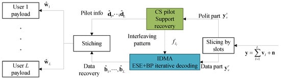
Figure 3.
Intra-slot decoder structure at slot v.
The ESE + BP iteration may continue for a specific number of times , and then the final hard-decision output at the BP decoder of each branch is stitched together with the corresponding pilot info part , reconstructing the complete payload decoding result .
3.2.2. Inter-Slot Decoder
To recover the superimposed multi-user packets on the overload slots, the inter-slot decoding performs SIC on the compound packet-level factor graph known by the reconstruction process. After the initial intra-slot decoding on all slots, the CS pilots should be recovered as pilot info , while the corresponding IDMA parts are not all successfully decoded, especially for those on the overload slots.
Using the CS pilots as pointers, the repetition relationship can be confirmed by comparing in one slot with on the others. According to Section 3.1.2, the number of unique pilots among all slots is the number of users . For user packet k, the indexes of the slots where a replica of it exists form a set:
where . We combine those sets as adjacent matrix , where the edge between user node k and slot node v is determined. Thus, the intra-slot packet spreading structure can be recovered as the compound factor graph in Figure 4. And The process of the inter-slot decoding described in Algorithm 1 is performed on this graph structure.
| Algorithm 1 Inter-slot SIC decoding on the compound packet-level factor graph |
|
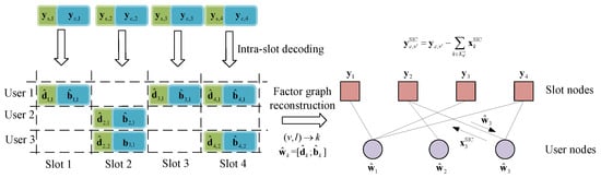
Figure 4.
An example for inter-slot factor graph reconstruction and SIC process, where and .
At the j-th SIC iteration, according to the T-Fold IRSA model, the slot nodes set can be separated into two subsets by the given threshold
where the initial slot node degree . Also, the user nodes set has two subsets, the successfully decoded set and the undecoded set . For each underload slot node that satisfies the decodable condition, add its adjacent user node k into . Based on this graph, the message passed from the user node to the slot node is the remapped decoded IDMA packet . After the SIC peeling session, if the degree of an overload slot node can be reduced under the threshold , this slot will be decodable, where its output message is the reliable decoded IDMA info parts . Define the effective edge set of slot as , then the decodable condition of overload slot after the j-th SIC is:
If this condition is satisfied, peel the known interference off on this slot:
Then send to the intra-slot decoder in Section 3.2.1, where the reliable decoded message can be recovered. Consequently, the user node subsets and can be updated by the backward messages. Perform this process on each overload slot . As a result, will decrease after each iteration, for the underload slots are always helping the overload ones by message propagation on the factor graph. Under appropriate conditions, the SIC can converge to the required level.
4. Performance Analysis and Parameter Optimization
The goal of the coding parameter optimization problem of the proposed scheme is to minimize the SNR threshold under a given PUPE (in Section 2). However, due to the complicated intra/inter-slot encoding structure, the relationship between the coding parameters and the performance indicator is not explicit. Therefore, this section addresses the problem by error event decomposition [16]. By breaking the system-level PUPE down to module-level error rates, the error contribution of each module can be analyzed and correlated with their parameters and eventually form a system-level parameter optimization problem.
4.1. Error Rate Analysis by Decomposition
According to the decoder structure described in Section 3.2, the PUPE in (1) can be decomposed into four parts, as depicted in Figure 5.
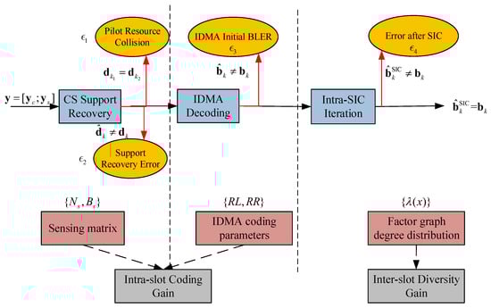
Figure 5.
The system-level packet loss broken down into module-level error events, with the corresponding coding parameters and coding gains.
Although, as described in Algorithm 1, the decoding structure consists of the compound intra/inter-slot iteration, it can nonetheless be regarded as a three-stage process when analyzing errors due to its successive style. The first stage is the CS pilot recovery, where the pilot resource collision occurs at the transmitter side and the support recovery error at the receiver side. The pilot plays three significant roles: the first part of the user payload, the user-specific IDMA interleaver, and the pointer used to reconstruct the packet-level factor graph. Thus, the pilot error will cause not only packet loss of its user but also the chain effect spreading to the correlated packets of other users. The IDMA decoding error and the remaining error after the intra-slot SIC process are both conditioned on the successfully recovered pilots. Then the modular errors are expressed as the functions of their corresponding coding parameters in (12).
The CS pilot parameters and are restricted by the collision and detection conditions. is the resource collision avoiding condition in [16]. The length of the separated pilot info part from user payload should be large enough to provide non-collision patterns. As for , the dimension of the sensing matrix is bounded by the Restricted Isometry Property (RIP) [31] condition. In other words, when is fixed, large row dimension can reduce the . Thus, we can conclude that and .
The IDMA block error rate is the function . According to the classical analysis of IDMA, is based on the single-user performance of the inner rate- FEC code and degrades with the gradually severe interference caused by the increase of the number of superimposed users . The SNR cost of at a required level can be extracted on the performance curve of a given threshold by simulation.
4.2. Inter-Slot Degree Distribution Analysis
As the SNR cost of the IDMA system increases with , the SIC decoding on the compound factor graph of the inter-slot code can further reduce the threshold to reach the same level of PUPE, resulting in the reduction of SNR threshold. Thus, degree distribution optimization aims to minimize .
First, we start with an idealized asymptotic investigation. Previously the T-Fold IRSA was modeled as a factor graph, on which the user node degree distribution determines the slot node degree distribution :
where denotes the binomial distribution. The probability of high-degree slot nodes increases with the average packet repetition rate and decreases with more slots V, representing intensified superposition. Figure 6a gives an example of this rule.
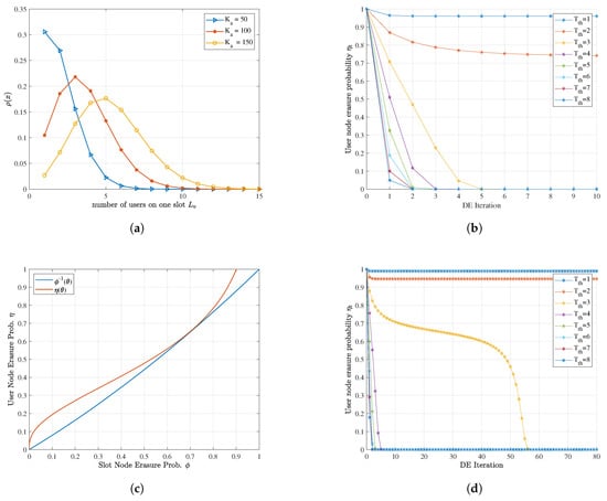
Figure 6.
Density evolution analysis of inter-slot code: (a) The degree distribution of slot nodes at and different users. (b) The density evolution procedure at , and , when it does not converge. (c) The density evolution EXIT chart at , , and . The tunnel is about to close, representing the boundary condition. (d) Corresponding density evolution iteration procedure at the same configuration with (c) but varying , where is just able to converge.
Moreover, the convergence behavior of the SIC on the factor graph can be characterized by density evolution (DE), which is similar to the LDPC message passing procedure under the erasure channel [32]. At the t-th iteration, the erasure probability of the slot nodes is and for the user nodes:
where at the beginning without a priori knowledge of user nodes, and can be derived from as in (13). Under appropriate , the erasure probability of slot nodes gradually descends with iteration. As is a positive-coefficient polynomial function, is monotonically increasing, indicating that also converges to 0 with descending . Meanwhile, the higher the threshold is, the higher the decodable probability of slot nodes is. Notice that the two-probability expression corresponds to the two message-passing procedures in Algorithm 1, respectively. Therefore, the SIC iteration can make as many overload user nodes decodable as possible. An example of the SIC procedure simulated by density evolution is depicted in Figure 6b. When V and are fixed, the cost of carrying more users is the increase of threshold to guarantee convergence under limited iterations, i.e., the rise of IDMA’s SNR requirement.
The tool to determine the convergence condition of density evolution iteration is its EXIT (EXtrinsic Information Transfer) chart [33]. Under given , V and , plot the erasure probability curves and in (14) on one chart, and find a trajectory between those two curves starting from . If the trajectory reaches , this enables the SIC iteration to converge, conversely not. Figure 6c,d shows a boundary condition case where the iteration tunnel is about to close for . Since , is always concave. Moreover, this effect becomes stronger when the weights of higher-order coefficients increase. However, it is not easy to explicitly express the boundary condition. We adopt the numerical method, differential evolution [34], to solve the implicit equation and search the range of suitable :
Then we move further to practical consideration. An important preassumption for density evolution analysis is that ensures the isotropy of distribution, while in practice, they are limited. It is challenging for the user-independent random schedulers to guarantee when is relatively small, especially for the repetition times with low probability (high-order degrees). On the other hand, the finite length effect causes short cycles and trapping loops in the randomly formed factor graph. In some worse cases, the SIC iteration cannot start or converge. Although the effect of can be ignored when considering boundary conditions, the remaining errors on the underload slot nodes may cause error propagation. Nonetheless, gives a basic scope, which just needs to be narrowed.
We use Monte-Carlo simulation to practically examine the effectiveness of candidates in . Under finite , V, and , the post-iteration packet loss rate of user nodes obtained by simulation is the actual PUPE. Besides, the cost of the packet diversity gain is the additional energy spent on repeated packets. The SNR threshold after inter-slot encoding is:
where is the SNR when reaches an effective level under threshold . After that, the trade-off of intra-slot encoding should also be considered.
4.3. Joint Parameter Optimization Algorithm
Integrating the analysis on the above modules, the complete parameter optimization procedure is proposed as Algorithm 2.
| Algorithm 2 Joint optimization of coding parameters |
|
Overall, we use a heuristic bootstrap method to jointly optimize the coding parameters analyzed above. The CS pilot configurations control and , basically determined by . To tackle the contradiction between intra-slot coding gain and inter-slot diversity gain, the IDMA rate R increases with iterations, while the inter-slot diversity decreases in each iteration. The initial rate R is randomly chosen, and then V can be determined. at is extracted on simulation curves. The convergence condition is ensured by (15). Then the effectiveness of with increasing energy cost is checked by simulation until it satisfies the post-SIC-iteration PUPE requirement. If the SNR threshold raises compared with the last iteration after optimization, R should be increased to enhance the inter-slot code. If not, lower R to reduce the multi-user interference.
5. Numerical Results
In this section, we evaluate the proposed scheme using numerical indexes of two aspects: the -SNR threshold curve representing energy efficiency and the FLOPf (FLoating-point Operations Per frame) comparison representing computational complexity.
5.1. Energy Efficiency Analysis
The SNR threshold, by definition, is the minimum required SNR that achieves a target PUPE under specific configurations. As described in Section 2, the -SNR curve is acquired under some fundamental constraints. Thus, we give the primary scenario configurations in Table 1.

Table 1.
Primary scenario and configurations in numerical simulations.
These parameters are shared in the following simulations. To get the SNR threshold for each , we optimize the coding parameters by Algorithm 2 point-by-point. The results are displayed in Table 2. Under all the configurations, and , so that the pilot error would not affect the subsequent decoders. Through adjustment, the intra-slot coding gain and inter-slot diversity gain are balanced, the sum of which reaches the optimal point.
Table 2.
Optimized coding parameters of the proposed scheme.
It can be observed that the proportion of the two types of gains varies with . In the low region, the intra-slot coding gain is more effective against multi-user interference, and the cost of reducing V is affordable. However, when it comes to the high region, the main problem is to tackle the rise of threshold by the inter-slot SIC. Meanwhile, the severe superposition of packets requires V to increase, so the inter-slot diversity gain dominates.
Next, we compare the proposed scheme with several existing representatives in Figure 7a. Based on the T-Fold Aloha scheme, the CCS-AMP [36] uses CS as the intra-slot encoder to resolve superposition and enhance the AMP algorithm. As introduced in Section 1, the CCS-AMP scheme is based on the T-Fold Aloha scheme, while SC-LDPC + SIC [20] and Polar-IRSA [21] are T-Fold IRSA. Sparse IDMA [13] and Polar-sparse spreading (Polar-SS) [15] are in the random spreading paradigm. Polar-IRSA achieves the best performance in the IRSA category with a better intra-slot code design. The excellent performance of polar codes in short length makes polar code base schemes stand out in low conditions where the intra-slot coding gain is critical. Our scheme occupies the middle position among the three for its repetition diversity in intra-slot IDMA code provides more coding gain than pure LDPC. The random spread spectrum schemes have the best performance of all paradigms, which can be decomposed into a cascaded structure on one frame-length long time slot. The sparse outer code can eliminate multi-user interference and provide a particular coding gain in the low region.
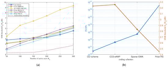
Figure 7.
(a) Comparison of -SNR threshold curves of different coding schemes. 30,000, , PUPE = 0.1. (b) Performance and computational complexity comparison at 30,000, , , PUPE = 0.1.
As increases, our scheme maintains the lowest slope and eventually achieves a performance advantage in the high region. This is mainly because we effectively control the increase of the threshold by utilizing fine optimization of the intra-slot gain and the inter-slot gain. The outer code of the sparse spreading schemes tends to be rateless, and its sparsity and gain gradually diminish. Meanwhile, other IRSA schemes only exploiting packet-level diversity suffer the same problem, let alone the bit-level spreading outperforms the packet-level one.
5.2. Complexity Analysis
Based on the analytical framework proposed in [10], the FLOPf can represent the complexity of the decoder. For each encoding scheme, FLOPf can be expressed as a function of its coding parameters. We compare the proposed scheme with Polar-RS, Polar-IRSA, and CCS-eAMP, the expressions of which are listed in Appendix A. When comparing these schemes, it is insightful to investigate the complexity cost of the corresponding energy efficiency gain. Figure 7b shows the SNR level and the required FLOPf of each scheme when the number of users reaches 150.
Although our scheme’s and CCS-AMP’s performance are the same, the latter costs about ten times more FLOPf than the former. Meanwhile, sparse IDMA spends 100 times more complexity for 0.4dB energy gain, while for the polar-RS scheme, it is for 0.8 dB. The intra-slot decoder is a linear iteration and converges after 3 to 5 iterations due to the high coding gain. Besides, the inter-slot iteration is restricted to 10 times by the joint degree distribution optimization. Therefore, our scheme achieves a better energy-complexity trade-off.
6. Conclusions
The proposed coding scheme achieves performance gain in the high region, benefitting from intra/inter-slot gain balance under jointly optimized parameters. Although it is not as good as existing solutions in the low region, it achieves a better trade-off between performance and complexity. The joint design of intra/inter-slot code exploits the potential of the T-Fold IRSA scheme more thoroughly. Thus, our scheme would be a prospective candidate for UMA design in next-generation IoT.
For future research, we can consider the fading scenario. Our scheme can easily be promoted to the block fading channel because of two inherent advantages: 1. Inserting the pilot at each slot means the channel response of each user at each slot can be independently estimated; 2. The intra-slot IDMA is a universal code. After optimizing it under the AWGN channel, its configuration can be directly applied to the fading scenario.
Author Contributions
Conceptualization, Y.L.; methodology, Y.L. and C.D.; software, Y.L.; validation, Y.L.; formal analysis, Y.L. and K.N.; investigation, Y.L. and C.D.; resources, S.S. and J.L.; data curation, Y.L., C.D. and S.S.; writing—original draft preparation, Y.L.; writing—review and editing, Y.L., C.D. and K.N.; visualization, Y.L.; supervision, C.D., K.N. and J.L.; project administration, S.S. and K.N.; funding acquisition, S.S. and K.N. All authors have read and agreed to the published version of the manuscript.
Funding
This work is supported by the Key Program of the National Natural Science Foundation of China (No. 92067202), the National Natural Science Foundation of China (No. 62071058), CICT Mobile Communication Technology Co., Ltd., and Beijing University of Posts and Telecommunications—China Mobile Research Institute Joint Innovation Center.
Institutional Review Board Statement
Not applicable.
Informed Consent Statement
Not applicable.
Data Availability Statement
Not applicable.
Conflicts of Interest
The authors declare no conflict of interest.
Abbreviations
The following abbreviations are used in this manuscript:
| UMA | Unsourced Multiple Access |
| IoT | Internet-of-Things |
| IRSA | Irregular Repeated Slotted Aloha |
| OMA | Orthogonal Multiple Access |
| NOMA | Non-Orthogonal Multiple Access |
| RACH | Random Access CHannel |
| PUPE | Per-User Probability of Error |
| IDMA | Interleave-Division Multiple Access |
| LDPC | Low Density Parity Check Code |
| RS | Random Spreading |
| SS | Sparse Spreading |
| SCL | Successive Cancellation List |
| SIC | Successive Interference Cancellation |
| BCH | Bose Ray-Chaudhuri and Hocquenghem |
| CS | Compressed Sensing |
| CCS | Coded Compressed Sensing |
| SPARC | SParse Rgression Code |
| AMP | Approximate Message Passing |
| SC-LDPC | Spatially Coupled-LDPC |
| BP | Belief Propagation |
| MIMO | Multi-Input Multi-Output |
| ESE | Elementary Symbol Estimator |
| SNR | Signal-to-Noise Ratio |
| OMP | Orthogonal Match Pursuit |
| AWGN | Additive White Gaussian Noise |
| LLR | Log-Likelihood Ratio |
| MUD | Multi-User Detection |
| EXIT | EXtrinsic Information Transfer |
| FLOPf | FLoating-point Operations Per frame |
Appendix A. The Expressions of FLOPf
The expressions of computational complexity and their corresponding coding parameters are in Table A1. The detailed optimized parameters of the compared schemes can be found in their respective papers.
Table A1.
FLOPf expressions of different coding schemes.
References
- You, X.; Wang, C.X.; Huang, J.; Gao, X.; Zhang, Z.; Wang, M.; Huang, Y.; Zhang, C.; Jiang, Y.; Wang, J.; et al. Towards 6G wireless communication networks: Vision, enabling technologies, and new paradigm shifts. Sci. China Inf. Sci. 2021, 64, 110301. [Google Scholar] [CrossRef]
- Giordani, M.; Polese, M.; Mezzavilla, M.; Rangan, S.; Zorzi, M. Toward 6G Networks: Use Cases and Technologies. IEEE Commun. Mag. 2020, 58, 55–61. [Google Scholar] [CrossRef]
- Chen, S.; Hu, J.; Shi, Y.; Zhao, L.; Li, W. A Vision of C-V2X: Technologies, Field Testing, and Challenges With Chinese Development. IEEE Internet Things J. 2020, 7, 3872–3881. [Google Scholar] [CrossRef]
- Sarkar, S.; Debnath, A. Green IoT: Design Goals, Challenges and Energy Solutions. In Proceedings of the 2021 6th International Conference on Communication and Electronics Systems (ICCES), Coimbatore, India, 8–10 July 2021; pp. 637–642. [Google Scholar] [CrossRef]
- Polyanskiy, Y. A perspective on massive random-access. In Proceedings of the IEEE International Symposium on Information Theory, Aachen, Germany, 25–30 June 2017; pp. 2523–2527. [Google Scholar] [CrossRef]
- Li, H.; Ru, G.; Kim, Y.; Liu, H. OFDMA capacity analysis in MIMO channels. IEEE Trans. Inf. Theory 2010, 56, 4438–4446. [Google Scholar] [CrossRef]
- Razavi, R.; Dianati, M.; Imran, M.A. Non-Orthogonal Multiple Access (NOMA) for future radio access. In 5G Mobile Communications; Springer: Cham, Switzerland, 2016; pp. 135–163. [Google Scholar] [CrossRef]
- Yuan, Y.; Wang, S.; Wu, Y.; Poor, H.V.; Ding, Z.; You, X.; Hanzo, L. NOMA for Next-Generation Massive IoT: Performance Potential and Technology Directions. IEEE Commun. Mag. 2021, 59, 115–121. [Google Scholar] [CrossRef]
- Wu, Y.; Gao, X.; Zhou, S.; Yang, W.; Polyanskiy, Y.; Caire, G. Massive Access for Future Wireless Communication Systems. IEEE Wirel. Commun. 2020, 27, 148–156. [Google Scholar] [CrossRef]
- Li, Y.; Dai, J.; Si, Z.; Niu, K.; Dong, C.; Lin, J.; Wang, S.; Yuan, Y. Unsourced multiple access for 6G massive machine type communications. China Commun. 2022, 19, 70–87. [Google Scholar] [CrossRef]
- Polonelli, T.; Brunelli, D.; Marzocchi, A.; Benini, L. Slotted aloha on lorawan-design, analysis, and deployment. Sensors 2019, 19, 838. [Google Scholar] [CrossRef] [PubMed]
- Liva, G. A slotted ALOHA scheme based on bipartite graph optimization. In Proceedings of the 2010 International ITG Conference on Source and Channel Coding, SCC 2010, Siegen, Germany, 18–21 January 2010; pp. 1–6. [Google Scholar]
- Pradhan, A.K.; Amalladinne, V.K.; Vem, A.; Narayanan, K.R.; Chamberland, J. A Joint Graph Based Coding Scheme for the Unsourced Random Access Gaussian Channel. In Proceedings of the 2019 IEEE Global Communications Conference (GLOBECOM), Waikoloa, HI, USA, 9–13 December 2019. [Google Scholar]
- Pradhan, A.K.; Amalladinne, V.K.; Narayanan, K.R.; Chamberland, J. Polar Coding and Random Spreading for Unsourced Multiple Access. In Proceedings of the ICC 2020—2020 IEEE International Conference on Communications (ICC), Virtual, 7–11 June 2020; pp. 1–6. [Google Scholar] [CrossRef]
- Zheng, M.; Wu, Y.; Zhang, W. Polar Coding and Sparse Spreading for Massive Unsourced Random Access. In Proceedings of the IEEE Vehicular Technology Conference, Virtual, 18 November–16 December 2020; pp. 1–4. [Google Scholar] [CrossRef]
- Ordentlich, O.; Polyanskiy, Y. Low complexity schemes for the random access Gaussian channel. In Proceedings of the IEEE International Symposium on Information Theory, Aachen, Germany, 25–30 June 2017; pp. 2528–2532. [Google Scholar] [CrossRef]
- Amalladinne, V.K.; Member, G.S.; Chamberland, J.f.; Member, S.; Narayanan, K.R. A Coded Compressed Sensing Scheme for Unsourced Multiple Access. IEEE Trans. Inf. Theory 2020, 66, 6509–6533. [Google Scholar] [CrossRef]
- Fengler, A.; Jung, P.; Caire, G. SPARCs and AMP for Unsourced Random Access. In Proceedings of the IEEE International Symposium on Information Theory, Paris, France, 7–12 July 2019; pp. 2843–2847. [Google Scholar] [CrossRef]
- Paolini, E.; Stefanović, Č.; Liva, G.; Popovski, P. Coded random access: Applying codes on graphs to design random access protocols. IEEE Commun. Mag. 2015, 53, 144–150. [Google Scholar] [CrossRef]
- Vem, A.; Narayanan, K.R.; Chamberland, J.F.; Cheng, J. A User-Independent Successive Interference Cancellation Based Coding Scheme for the Unsourced Random Access Gaussian Channel. IEEE Trans. Commun. 2019, 67, 8258–8272. [Google Scholar] [CrossRef]
- Marshakov, E.; Balitskiy, G.; Andreev, K.; Frolov, A. A polar code based unsourced random access for the gaussian MAC. In Proceedings of the 2019 IEEE 90th Vehicular Technology Conference (VTC2019-Fall), Honolulu, HI, USA, 22–25 September 2019; pp. 1–5. [Google Scholar] [CrossRef]
- Glebov, A.; Matveev, N.; Andreev, K.; Frolov, A.; Turlikov, A. Achievability Bounds for T-Fold Irregular Repetition Slotted ALOHA Scheme in the Gaussian MAC. In Proceedings of the IEEE Wireless Communications and Networking Conference, WCNC, Marrakesh, Morocco, 15–18 April 2019; pp. 12–17. [Google Scholar] [CrossRef]
- Polyanskiy, Y.; Poor, H.V.; Verdú, S. Channel coding rate in the finite blocklength regime. IEEE Trans. Inf. Theory 2010, 56, 2307–2359. [Google Scholar] [CrossRef]
- Kowshik, S.S.; Polyanskiy, Y. Fundamental Limits of Many-User MAC With Finite Payloads and Fading. IEEE Trans. Inf. Theory 2021, 67, 5853–5884. [Google Scholar] [CrossRef]
- Kowshik, S.S.; Andreev, K.; Frolov, A.; Polyanskiy, Y. Energy efficient random access for the quasi-static fading MAC. In Proceedings of the IEEE International Symposium on Information Theory, Paris, France, 7–12 July 2019; pp. 2768–2772. [Google Scholar] [CrossRef]
- Li, T.; Wu, Y.; Zheng, M.; Wang, D.; Zhang, W. SPARC-LDPC Coding for MIMO Massive Unsourced Random Access. In Proceedings of the IEEE Globecom Workshops, Taipei, Taiwan, 7–11 December 2020; pp. 8–13. [Google Scholar]
- Wang, Q.; Liu, L.; Zhang, S.; Lau, F.C. On Massive IoT Connectivity with Temporally-Correlated User Activity. In Proceedings of the IEEE International Symposium on Information Theory, Melbourne, Australia, 12–20 July 2021; pp. 3020–3025. [Google Scholar] [CrossRef]
- Fengler, A.; Haghighatshoar, S.; Jung, P.; Caire, G. Non-Bayesian Activity Detection, Large-Scale Fading Coefficient Estimation, and Unsourced Random Access with a Massive MIMO Receiver. IEEE Trans. Inf. Theory 2021, 67, 2925–2951. [Google Scholar] [CrossRef]
- Koep, N.; Behboodi, A.; Mathar, R. An Introduction to Compressed Sensing. In Applied and Numerical Harmonic Analysis; Birkhäuser: Cham, Switzerland, 2019. [Google Scholar] [CrossRef]
- Xiong, X.; Hu, J.; Tian, L. A fast converging multi-user detection for IDMA based on time-reversal. In Proceedings of the 2007 6th International Conference on Information, Communications and Signal Processing, ICICS, Singapore, 10–13 December 2007. [Google Scholar] [CrossRef]
- Leinonen, M.; Codreanu, M.; Giannakis, G.B. Compressed Sensing with Applications in Wireless Networks; Now Foundations and Trends: Boston, MA, USA, 2019. [Google Scholar] [CrossRef]
- Richardson, T.; Urbanke, R. Modern Coding Theory; Cambridge University Press: Cambridge, UK, 2008. [Google Scholar] [CrossRef]
- Hagenauer, J. The exit chart—Introduction to extrinsic information transfer in iterative processing. In Proceedings of the 2004 12th European Signal Processing Conference, Vienna, Austria, 6–10 September 2004; pp. 1541–1548. [Google Scholar]
- Price, K.V. Differential evolution. In Handbook of Optimization; Springer: Berlin/Heidelberg, Germany, 2013; pp. 187–214. [Google Scholar]
- 3GPP. TS 138 212-V15. 2.0-5G; NR; Multiplexing and Channel Coding (3GPP TS 38.212 Version 15.2. 0 Release 15). Retrieved. 26 June 2022. Available online: https://www.etsi.org/deliver/etsi_ts/138200_138299/138212/15.02.00_60/ts_138212v150200p.pdf (accessed on 29 September 2022).
- Amalladinne, V.K.; Kumar Pradhan, A.; Rush, C.; Chamberland, J.F.; Narayanan, K.R. On Approximate Message Passing for Unsourced Access with Coded Compressed Sensing. In Proceedings of the 2020 IEEE International Symposium on Information Theory (ISIT), Los Angeles, CA, USA, 21–26 June 2020; pp. 2995–3000. [Google Scholar] [CrossRef]
- Calderbank, R.; Thompson, A. CHIRRUP: A practical algorithm for unsourced multiple access. Inf. Inference 2020, 9, 875–897. [Google Scholar] [CrossRef]


Disclaimer/Publisher’s Note: The statements, opinions and data contained in all publications are solely those of the individual author(s) and contributor(s) and not of MDPI and/or the editor(s). MDPI and/or the editor(s) disclaim responsibility for any injury to people or property resulting from any ideas, methods, instructions or products referred to in the content. |
© 2022 by the authors. Licensee MDPI, Basel, Switzerland. This article is an open access article distributed under the terms and conditions of the Creative Commons Attribution (CC BY) license (https://creativecommons.org/licenses/by/4.0/).