
Insights into the Issue of Deploying a Private LoRaWAN


Abstract
:1. Introduction
1.1. Internet of Things Connectivity
1.2. Contribution and Structure of This Study
2. Background and State of the Art
- Selected channel (CH) or sub-band (f) determines the maximum transmit power (10 mW, 25 mW, or 500 mW), which impacts, for example, the communication range, material penetration capability, signal propagation, and the duty-cycle (0.1%, 1%, 10%, or 100%), which impacts the allowed transmission frequency and thus the maximum data rate.
- Bandwidth (BW) established for Europe is either 125 kHz or 250 kHz.
- Modulation (MOD); LoRaWAN specifies two types of modulation: (i) FSK, and (ii) LoRa modulation. The FSK demands higher signal-to-noise ratio (SNR) and thus is typically used when the communication channel is good and communication range is relatively short. Compared to FSK, the LoRa modulation offers a 13 dB better channel budget and Doppler resistance and approx. 10–20 dB increased interference immunity.
- Spreading factor (SF) is defined as and determines the symbol duration , where the chirp interval is defined by BW as . Moreover, the SF together with BW define the physical layer bit-rate:
- Code rate (CR) is defined as , where the rate and determines redundant bits used for forward error correction—FEC (impacts the ability to correct damaged messages and error-rates). LoRaWAN prescribes use of for packet payload, and for the packet header.
- Device class, which defines the type of media access for downlink traffic, which also affects the end-device’s power consumption (class A—downlink only after uplink and the minimum consumed power; class B—periodic downlink slots with slightly higher device consumption; class C—highest consumption for devices, but downlink can be sent any time).
- Device settings provide a number of other configuration capabilities, including activation (over-the-air activation—OTAA or activation by personalization—ABP), key-generation, firmware updates, data rate (adaptive data rate—ADR, or fixed data rate—FDR), and others).
- Public network—the network is always owned by a third party (public operator of national or international scale), gateways are deployed to provide coverage over large geographical areas (wide area network—WAN), and for the end-user: fixed parameters of the network, non-transparent and uncontrolled environment, expected lower capital (no need to build the infrastructure), questionable operational expenses (based on the fees and scale), simple and fast deployment, and low technological and management requirements.
- Private network—the network is owned by the end-user (i.e., city, company, or individual), gateways are typically deployed to provide coverage over smaller geographical areas (i.e., local, campus, or metropolitan), dynamical (customizable) parameters of network for end-users, transparent and controlled environment for end-users, expected higher capital and questionable operational expenses (based on scale), more complex deployment, and higher technological and management requirements.
3. Experimental Environment
3.1. Private Lorawan
- Transmit power up to +27 dBm (500 mW, the power was always based on the selected channel and allowed value from the regulation recommendation [31]).
- Received signal sensitivity up to −138 dBm.
- Five dBi antenna.
- Communication range up to 25 km.
- Up to eight simultaneous receiving channels.
- Up to 60 thousand nodes.
- Whole gateway covered in an IP67 case.
3.2. Public Lorawan
3.3. Test Device
- Static node (no movement during measurement).
- Transmit power of 14 dBm (25 mW).
- Spreading factor 12.
- ABP activation (OTAA was not supported by public network operator that time), fixed data rate (adaptive data rate was not supported by public network that time).
- Sensitivity up to −140 dBm, 0 dBi wire antenna (Thermolast K TC7AA).
- Communication range up to 15 km.
- Device temperature limits −30 to +70 °C.
4. Experimental and Analytical Results
- Performance evaluation—provides an evaluation of the performance of the public and the private networks. First, we report the results of the outdoor measurements to confirm our claim about the importance of channel selection and its impact on the network parameters (signal strength, signal-to-noise ratio, and loss rate). Further, we provide extensive experimental measurement results for indoor scenario, coverage, penetration, and loss rate, which should give a sufficient overview of the LoRaWAN behavior in the indoor environment.
- Security evaluation—gives accurate information about the recent changes in the LoRaWAN protocol based on the newest documentation. We look at the basics of information security parameters, such as authentication, encryption, and data integrity, but also at key establishment and key update. We also discuss possible vulnerabilities and compare the older with the newest version of the LoRaWAN protocol. Finally, we summarize the differences regarding security in private and public networks.
- Deployment ease evaluation—introduces the deployment difficulties, a methodology for the deployment of the public or private network, and evaluates the possible expenses in the context of private and public networks.
4.1. Performance Evaluation
4.1.1. Impact of Channel Selection on Network Performance
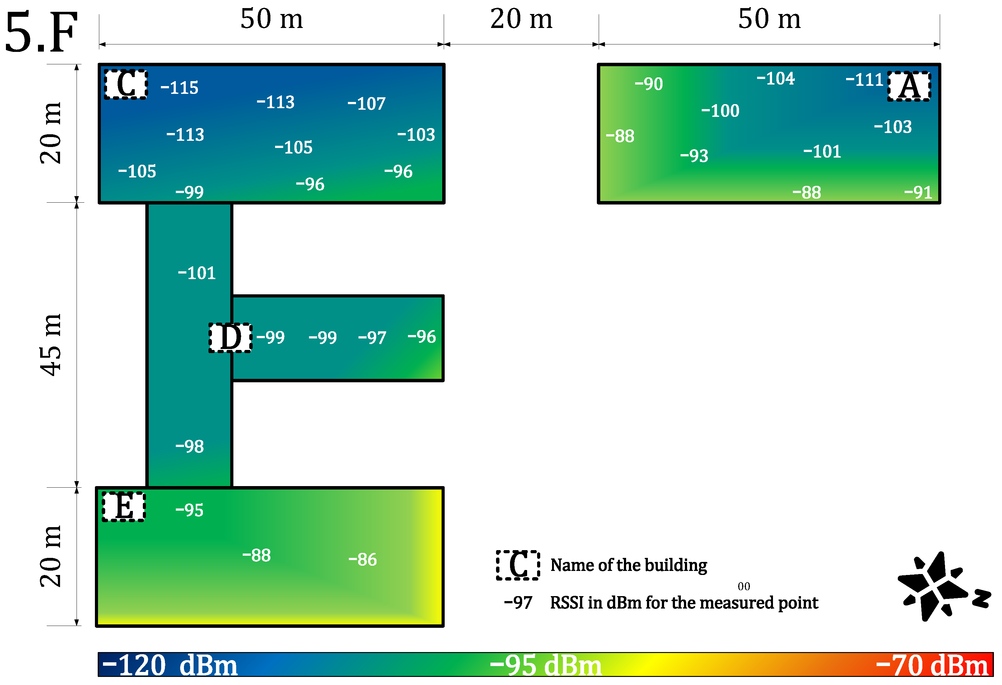
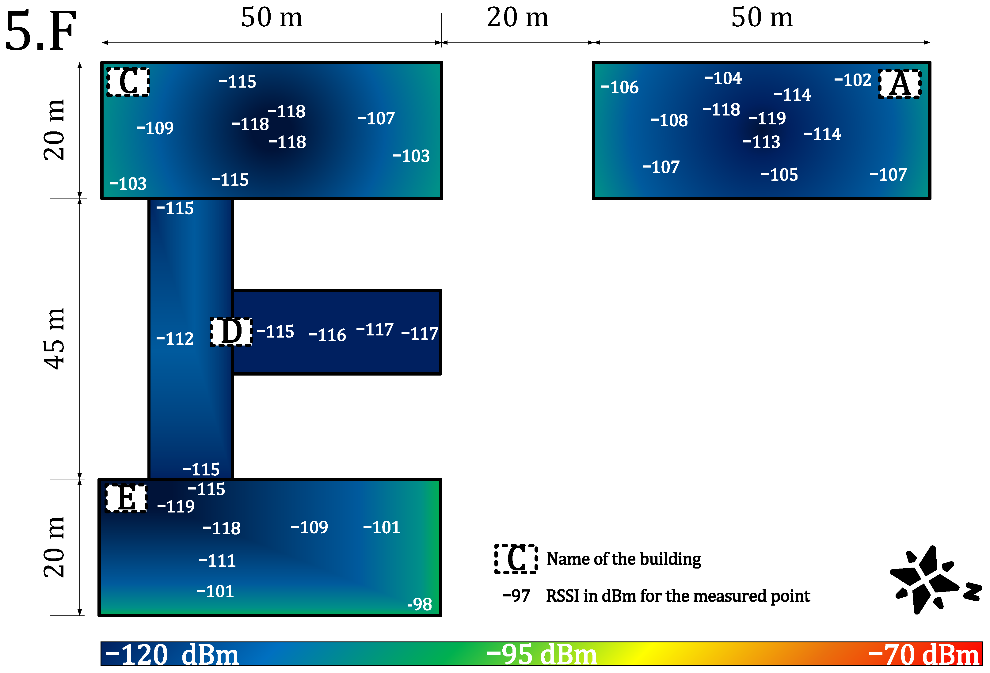
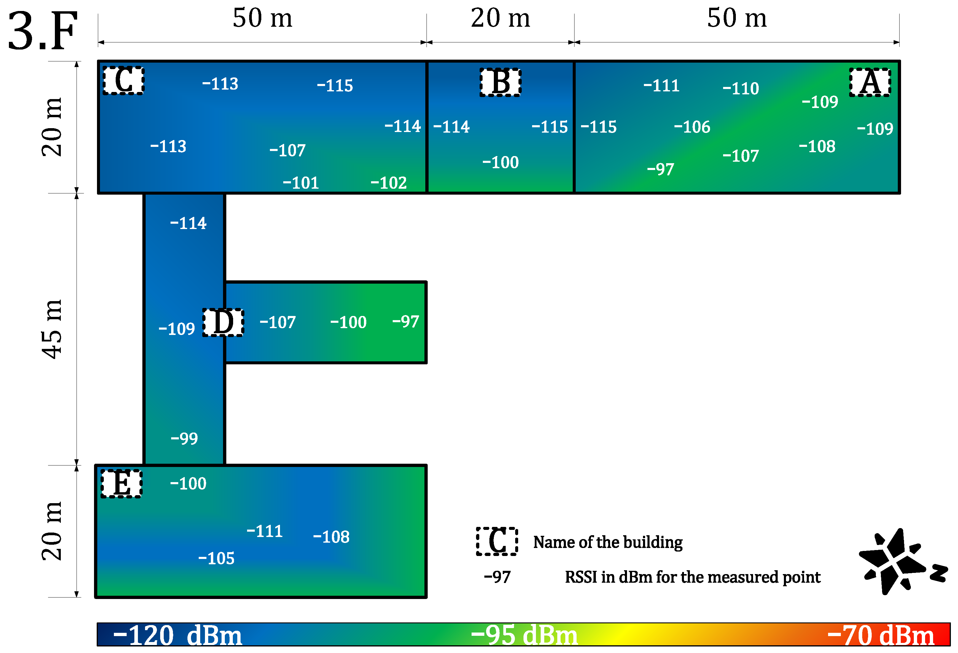
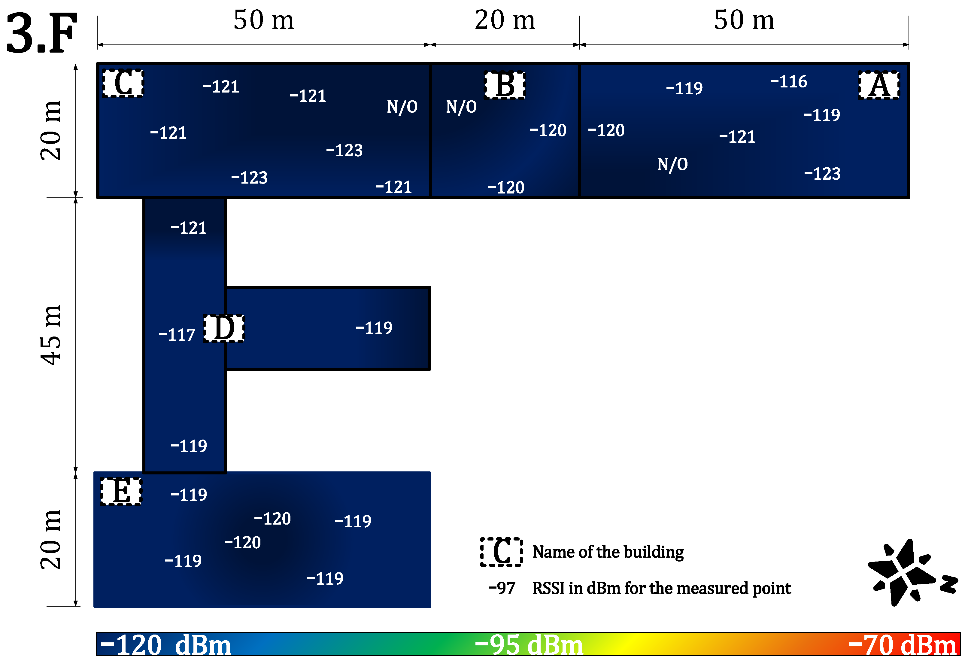
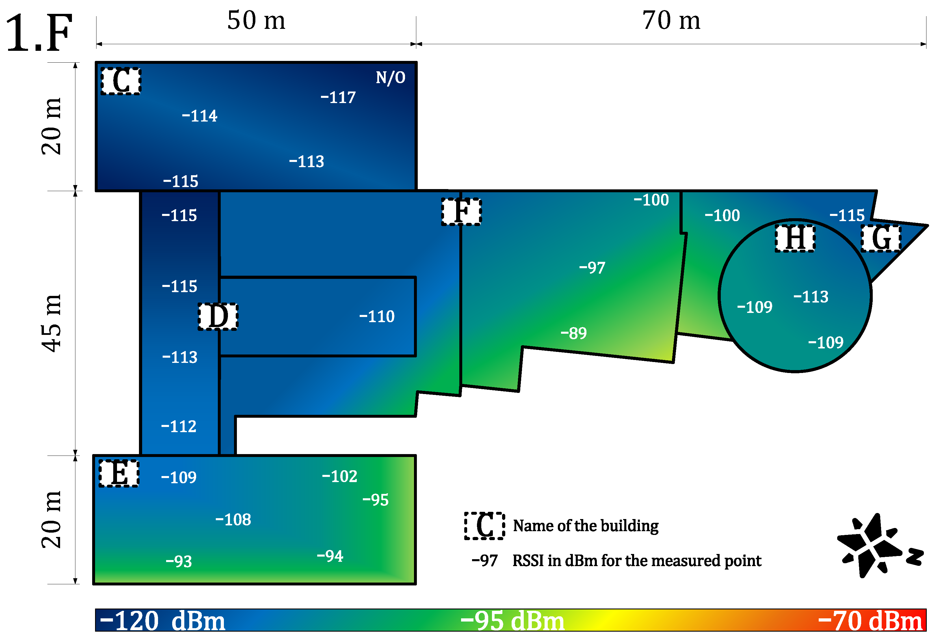
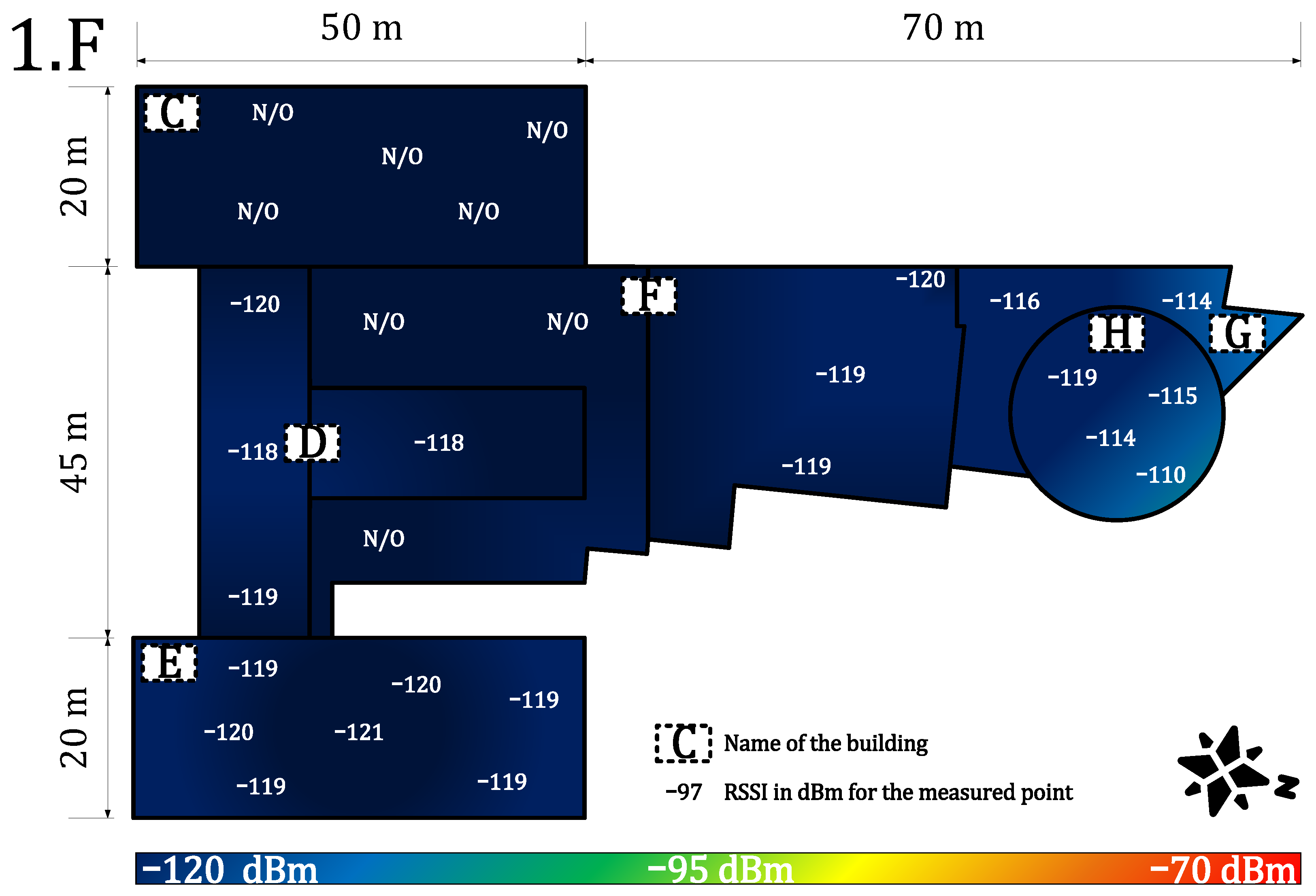
4.1.2. Indoor Coverage and Signal Propagation
4.2. Security Evaluation
4.2.1. Vulnerabilities
- The preshared key AppKey cannot be updated. The key update problem is discussed in [70].
- The keys are persistently stored on a LoRaWAN device and could be subject to physical attacks. Using a tamper-resistant storage (i.e., secure element, HSM) improves the security of the stored key, but it also increases the costs.
- The paper [71] demonstrates that LoRaWAN transmissions are prone to jamming attacks.
- The paper [72] shows that the OTAA approach enables attackers to conduct a replay attack.
- The operator’s NS knows the application keys and can decrypt the end-to-end communication, as noted in [73] (fixed in 1.0.4).
- The paper [74] shows potential vulnerabilities to denial of service (DoS) attacks during the join procedure.
4.2.2. The State-of-the-Art Improvements
4.2.3. Security Improvements in LoRaWAN™ 1.1 Specification
4.2.4. Security Improvements in LoRaWAN™ 1.0.4 Specification
4.2.5. Security Comparison of Private and Public Network
4.3. Deployment Ease Evaluation
4.3.1. Deployment Costs Evaluation
4.3.2. Methodology of Deployment
- 1.
- Estimate the size of the network (geographic area, number of gateways for a private case, number of nodes, density of nodes), desired service parameters (availability, throughput, type of communication, latency, communication frequency), and desired additional services (such as localization service presence).
- 2.
- Determine the possible future growth of the network or the network requirements. In addition, determine the possible future growth of the environment (i.e., new shopping areas, industrial complexes, and other noise-generating elements).
- 3.
- Analyze the feasibility of handling these requirements and future needs by LoRaWAN accounting for frequency regulations and technology limitations (check the availability of desired devices for the selected application). Decide whether the LoRaWAN technology is suitable for the selected use case. If possible, make a cost-efficiency analysis for LoRaWAN and other technologies (include the cost of development if end-devices are not available).
- 4.
- Use tester device(s) to characterize the signal quality of the public service from the most remote and difficult points (ask for an exact frequency plan of the network service provider). Discuss the possibilities of service-level agreement (SLA) with the public operator. Based on the results, selected parameters, and cost-efficiency, decide whether to go for either the private or the public network.
- 1.
- Estimation of the network coverage should be computed via simulation tools, i.e., Radio Mobile. This software uses the Irregular Terrain Model (ITS) based on the Longley–Rice model, which is a method for predicting the attenuation of radio signals for a telecommunication link in the frequency range of 20 MHz to 20 GHz. Based on the results, the position of the gateways should be established with reference to the simulation and also the node density. However, the best position may not be always available, and the location of already owned infrastructure should also be considered).
- 2.
- Make a noise analysis and select a frequency plan. Deploy the gateways based on the estimated plan.
- 3.
- Select power levels and data rates (if adaptive data rate is not in use) for the nodes. Use the tester device to characterize the quality of the signal from the most remote and difficult points.
- 4.
- Optimize the network by replacing or adding gateways and device antennas.
- 5.
- Deploy the first devices and test the long-term parameters of the network by monitoring the main parameters, i.e., availability and latency.
- 6.
- Scale the network up by continuously monitoring the main metrics.
- 7.
- The network parameters will change continuously over time, and the network needs to be continuously optimized to preserve the required parameters.
- 1.
- To ensure the performance metrics, agree with the public operator on the parameters via SLA.
- 2.
- Select power levels and data rates (if adaptive data rate is not in use) for the nodes.
- 3.
- Deploy the first devices and test the long-term parameters of the network by monitoring the main parameters, i.e., availability or latency.
- 4.
- Scale the network up by continuously monitoring the main parameters
- 5.
- The network parameters will change continuously over time, and it is necessary to continuously control the SLA from the operator.
4.4. Results Discussion
5. Conclusions and Future Work
Author Contributions
Funding
Institutional Review Board Statement
Informed Consent Statement
Data Availability Statement
Conflicts of Interest
References
- Le, N.T.; Hossain, M.A.; Islam, A.; Kim, D.; Choi, Y.; Jang, Y.M. Survey of Promising Technologies for 5G Networks. Mob. Inf. Syst. 2016, 2016, 2676589. [Google Scholar] [CrossRef] [Green Version]
- IoT Connections Outlook, Broadband IoT Set to Overtake 2G and 3G. Available online: https://www.ericsson.com/en/reports-and-papers/mobility-report/dataforecasts/iot-connections-outlook (accessed on 8 February 2022).
- Chen, X.Y.; Jin, Z.G. Research on Key Technology and Applications for Internet of Things. Phys. Procedia 2012, 33, 561–566. [Google Scholar] [CrossRef] [Green Version]
- Goudos, S.K.; Dallas, P.I.; Chatziefthymiou, S.; Kyriazakos, S. A Survey of IoT Key Enabling and Future Technologies: 5G, Mobile IoT, Sematic Web and Applications. Wirel. Pers. Commun. 2017, 97, 1645–1675. [Google Scholar] [CrossRef]
- Poorter, E.D.; Hoebeke, J.; Strobbe, M.; Moerman, I.; Latré, S.; Weyn, M.; Lannoo, B. Sub-GHz LPWAN Network Coexistence, Management and Virtualization: An Overview and Open Research Challenges. Wirel. Pers. Commun. 2017, 95, 187–213. [Google Scholar] [CrossRef] [Green Version]
- Centenaro, M.; Vangelista, L.; Zanella, A.; Zorzi, M. Long-range communications in unlicensed bands: The rising stars in the IoT and smart city scenarios. IEEE Wirel. Commun. 2016, 23, 60–67. [Google Scholar] [CrossRef] [Green Version]
- Goursaud, C.; Gorce, J. Dedicated networks for IoT: PHY/MAC state of the art and challenges. EAI Endorsed Trans. Internet Things 2015, 15, 1–11. [Google Scholar] [CrossRef]
- Yang, W.; Wang, M.; Zhang, J.; Zou, J.; Hua, M.; Xia, T.; You, X. Narrowband Wireless Access for Low-Power Massive Internet of Things: A Bandwidth Perspective. IEEE Wirel. Commun. 2017, 24, 138–145. [Google Scholar] [CrossRef]
- Adelantado, F.; Vilajosana, X.; Tuset-Peiro, P.; Martinez, B.; Melià-Saguí, J.; Watteyne, I.T. Understanding the limits of LoRaWAN. IEEE Commun. Mag. 2017, 55, 34–40. [Google Scholar] [CrossRef] [Green Version]
- LoRa Alliance. LoRaWAN™ 1.1 Specification. Technical Specification; [Final Release, October]. 2017. Available online: https://resources.lora-alliance.org/technical-specifications/lorawan-specification-v1-1 (accessed on 8 February 2022).
- Therdpong, D.; Pana, U. WUTTIDITTACHOTTI, Pongpisit. A Study of 5G Network Performance: A Pilot Field Trial at the Main Skytrain Stations in Bangkok. In Proceedings of the 2021 International Conference on Artificial Intelligence and Computer Science Technology (ICAICST), Yogyakarta, Indonesia, 29–30 June 2021; pp. 191–195. [Google Scholar]
- Gbadamosi, S.A.; Hancke, G.P.; Abu-Mahfouz, A.M. Building Upon NB-IoT Networks: A Roadmap Towards 5G New Radio Networks. IEEE Access 2020, 8, 188641–188672. [Google Scholar] [CrossRef]
- Sinha, R.S.; Wei, Y.; Hwang, S.-H. A survey on LPWA technology: Lora and Nb-IOT. ICT Express 2017, 3, 14–21. [Google Scholar] [CrossRef]
- AlarmNet. Network Overview. Technical Report. 2005. Available online: http://library.ademconet.com/MWT/fs2/7810IR/AlarmNet-network-overview.pdf (accessed on 8 February 2022).
- Seller, O.B.A.; Sornin, N. Low Power Long Range Transmitter. E.U. Patent EP 2763321 A1, 5 February 2013. [Google Scholar]
- Hornbuckle, C.A. Fractional-N synthesized chirp generator. U.S. Patent US 7791415 B2, 18 May 2007. [Google Scholar]
- LoRa Alliance. LoRaWAN™ Backend Interfaces 1.0 Specification. Technical Specification; [Final Release, October]. 2017. Available online: https://lora-alliance.org/wp-content/uploads/2020/11/lorawantm-backend-interfaces-v1.0.pdf (accessed on 8 February 2022).
- Pekar, A.; Mocnej, J.; Seah, W.K.; Zolotova, I. Application domain-based overview of IOT network traffic characteristics. ACM Comput. Surv. 2021, 53, 1–33. [Google Scholar] [CrossRef]
- Osorio, A.; Calle, M.; Soto, J.D.; Candelo-Becerra, J.E. Routing in LoRaWAN: Overview and Challenges. IEEE Commun. Mag. 2020, 58, 72–76. [Google Scholar] [CrossRef]
- Haxhibeqiri, J.; Poorter, E.D.; Moerman, I.; Hoebeke, J. A survey of Lorawan for IOT: From technology to application. Sensors 2018, 18, 3995. [Google Scholar] [CrossRef] [PubMed] [Green Version]
- Citoni, B.; Fioranelli, F.; Imran, M.A.; Abbasi, Q.H. Internet of Things and LoRaWAN-Enabled Future Smart Farming. IEEE Internet Things Mag. 2019, 2, 14–19. [Google Scholar] [CrossRef] [Green Version]
- Pinto-Erazo, A.M.; Suárez-Zambrano, L.E.; Mediavilla-Valverde, M.M.; Andrade-Guevara, R.E. Introductory analysis of Lora/Lorawan Technology in Ecuador. Commun. Smart Technol. Innov. Soc. 2021, 547–557. [Google Scholar] [CrossRef]
- Mekki, K.; Bajic, E.; Chaxel, F.; Meyer, F. A comparative study of LPWAN technologies for large-scale IoT deployment. ICT Express 2019, 5, 1–7. [Google Scholar] [CrossRef]
- Kajati, E.; Papcun, P.; Liu, C.; Zhong, R.Y.; Koziorek, J.; Zolotova, I. Cloud based cyber-physical systems: Network Evaluation Study. Adv. Eng. Inf. 2019, 42, 100988. [Google Scholar] [CrossRef]
- Noura, H.; Hatoum, T.; Salman, O.; Yaacoub, J.-P.; Chehab, A. Lorawan security survey: Issues, threats and possible mitigation techniques. Internet Things 2020, 12, 100303. [Google Scholar] [CrossRef]
- Raza, U.; Kulkarni, P.; Sooriyabandara, M. Low Power Wide Area Networks: An Overview. IEEE Commun. Surv. Tutor. 2017, 19, 855–873. [Google Scholar] [CrossRef] [Green Version]
- Andreev, S.; Galinina, O.; Pyateav, A.; Gerasimenko, M.; Tirronen, T.; Torsner, J.; Sachs, J.; Dohler, M.; Koucheryavy, Y. Understanding the IoT connectivity landscape: A contemporary M2M radio technology roadmap. IEEE Commun. Mag. 2015, 53, 32–40. [Google Scholar] [CrossRef] [Green Version]
- Knyazev, N.S.; Chechetkin, V.A.; Letavin, D.A. Comparative analysis of standards for Low-power Wide-area Network. In Proceedings of the 2017 IEEE Systems of Signal Synchronization, Generating and Processing in Telecommunications, Kazan, Russia, 3–4 July 2017; pp. 1–4. [Google Scholar]
- Sethi, P.; Sarangi, S.R. Internet of Things: Architectures, Protocols, and Applications. J. Electr. Comput. Eng. 2017, 2017, 9324035. [Google Scholar] [CrossRef] [Green Version]
- Silva, J.C.; Rodrigues, J.J.P.C.; Alberti, A.M.; Solic, P.; Aquino, A.L.L. LoRaWAN-A Low Power WAN Protocol for Internet of Things: A Review and Opportunities. In Proceedings of the 2017 2nd International Multidisciplinary Conference on Computer and Energy Science, Split, Croatia, 12–14 July 2017; pp. 1–6. [Google Scholar]
- CEPT-Electronic Communications Committee. Recommendation 70–03 Relating to the Use of Short Range Devices (SRD), Technical Recommendation/Regulation; Denmark, Copenhagen [Version from October 2017]; 2017. Available online: https://docdb.cept.org/download/25c41779-cd6e/Rec7003e.pdf (accessed on 8 February 2022).
- Vangelista, L.; Zanella, A.; Zorzi, M. Long-range IoT technologies: The dawn of LoRa™. In Proceedings of the Future Access Enablers for Ubiquitous and Intelligent Infrastructures, Lecture Notes of the Institute for Computer Sciences, Social Informatics and Telecommunications Engineering; Atanasovski, V., Leon-Garcia, A., Eds.; Springer: Cham, Switzerland, 2015; Volume 159, pp. 51–58. [Google Scholar]
- Bardyn, J.; Melly, T.; Seller, O.; Sornin, N. IoT: The era of LPWAN is starting now. In Proceedings of the 2016 IEEE 42nd European Solid-State Circuits Conference, Lausanne, Switzerland, 12–15 September 2016; pp. 25–30. [Google Scholar]
- Semtech Corporation. AN1200.22: LoRa™ Modulation Basics. Application note. 2015 [Revision 2, May]. Available online: https://www.frugalprototype.com/wp-content/uploads/2016/08/an1200.22.pdf (accessed on 8 February 2022).
- Vejlgaard, B.; Lauridsen, M.; Nguyen, H.C.; Mogensen, I.K.P.E.; Søreosen, M. Coverage and Capacity Analysis of Sigfox, LoRa, GPRS, and NB-IoT. In Proceedings of the 2017 IEEE 85th Vehicular Technology Conference, Sydney, NSW, Australia, 4–7 June 2017; pp. 1–5. [Google Scholar]
- Seye, M.R.; Gueye, B.; Diallo, M. An evaluation of LoRa coverage in Dakar Peninsula. In Proceedings of the 2017 IEEE 8th Annual Information Technology, Electronics and Mobile Communication Conference, Vancouver, BC, Canada, 3–5 October 2017; pp. 478–482. [Google Scholar]
- Petajajarvi, J.; Mikhaylov, K.; Roivainen, A.; Hanninen, T.; Pettissalo, M. On the Coverage of LPWANs: Range Evaluation and Channel Attenuation Model for LoRa Technology. In Proceedings of the 2015 IEEE 14th International conference on ITS Telecommunications, Copenhagen, Denmark, 2–4 December 2015; pp. 1–6. [Google Scholar]
- Aref, M.; Sikora, A. Free space measurements with Semtech LoRa technology. In Proceedings of the 2014 IEEE 2nd Inernational Symposium on Wireless Systems within the Conferences on Intelligent Data Acquisition and Advanced Computing Systems: Technology and Applications, Odessa, UKraine, 11–12 September 2014; pp. 19–23. [Google Scholar]
- Barriquello, C.H.; Bernardon, D.P.; Canha, L.N.; Silva, F.E.S.; Porto, D.S.; Ramos, M.J.S. Performance assessment of a low power wide area network in rural smart grids. In Proceedings of the 2017 IEEE 52nd International Universities Power Engineering Conference, Heraklion, Greece, 28–31 August 2017; pp. 1–4. [Google Scholar]
- Casals, L.; Mir, B.; Vidal, R.; Gomez, C. Modeling the energy performance of LoRaWAN. Sensors 2017, 17, 2364. [Google Scholar] [CrossRef] [PubMed] [Green Version]
- Lauridsen, M.; Nguyen, H.; Vejlgaard, B.; Kovacs, I.Z.; Mogensen, P.; Sorensen, M. Coverage Comparison of GPRS, NB-IoT, LoRa, and SigFox in a 7800 km² Area. In Proceedings of the 2017 IEEE 85th Vehicular Technology Conference, Sydney, NSW, Australia, 4–7 June 2017; pp. 1–5. [Google Scholar]
- Petajajarvi, J.; Mikhaylov, K.; Pettissalo, M.; Janhunen, J.; Iinatti, J. Performance of a low-power wide-area network based on LoRa technology: Doppler robustness, scalability, and coverage. Int. J. Distrib. Sens. Netw. 2017, 13, 1–21. [Google Scholar] [CrossRef] [Green Version]
- Patel, D.; Won, M. Experimental Study on Low Power Wide Area Networks (LPWAN) for Mobile Internet of Things. In Proceedings of the 2017 IEEE 85th Vehicular Technology Conference, Sydney, NSW, Australia, 4–7 June 2017; pp. 1–5. [Google Scholar]
- Petrić, T.; Goessens, c.; Nuaymi, L.; Toutain, L.; Pelov, A. Measurements, performance and analysis of LoRa FABIAN, a real-world implementation of LPWAN. In Proceedings of the 2016 IEEE 27th Annual International Personal, Indoor, and Mobile Radio Communications, Valencia, Spain, 4–8 September 2016; pp. 1–7. [Google Scholar]
- Almuhaya, M.A.; Jabbar, W.A.; Sulaiman, N.; Abdulmalek, S. A survey on Lorawan technology: Recent trends, opportunities, simulation tools and future directions. Electronics 2022, 11, 164. [Google Scholar] [CrossRef]
- Goldoni, E.; Savazzi, P.; Favalli, L.; Vizziello, A. Correlation between weather and signal strength in Lorawan Networks: An extensive dataset. Comput. Netw. 2022, 202, 108627. [Google Scholar] [CrossRef]
- Masek, P.; Stusek, M.; Svertoka, E.; Pospisil, J.; Burget, R.; Lohan, E.S.; Marghescu, I.; Hosek, J.; Ometov, A. Measurements of LoRaWAN Technology in Urban Scenarios: A Data Descriptor. Data 2021, 6, 62. [Google Scholar] [CrossRef]
- Centelles, R.P.; Freitag, F.; Meseguer, R.; Navarro, L. Beyond the Star of Stars: An Introduction to Multihop and Mesh for LoRa and LoRaWAN. IEEE Pervasive Comput. 2021, 20, 63–72. [Google Scholar] [CrossRef]
- Mocnej, J.; Pekar, A.; Seah, W.K.G.; Papcun, P.; Kajati, E.; Cupkova, D.; Koziorek, J.; Zolotova, I. Quality-enabled decentralized IOT architecture with efficient resources utilization. Robot. Comput.-Integr. Manuf. 2021, 67, 102001. [Google Scholar] [CrossRef]
- Leenders, G.; Callebaut, G.; Ottoy, G.; der Perre, L.V.; Strycker, L.D. Multi-RAT for IoT: The Potential in Combining LoRaWAN and NB-IoT. IEEE Commun. Mag. 2021, 59, 98–104. [Google Scholar] [CrossRef]
- Navarro-Ortiz, J.; Sendra, S.; Ameigeiras, P.; Lopez-Soler, J.M. Integration of LoRaWAN and 4G/5G for the Industrial Internet of Things. IEEE Commun. Mag. 2018, 56, 60–67. [Google Scholar] [CrossRef]
- Kulkarni, P.; Pradeep, B.; Raza, U.; Alsaedi, S.; Almadhaani, R. LoRaWAN in Licensed Access Spectrum? A Techno-Economic Perspective. IEEE Internet Things Mag. 2020, 3, 70–75. [Google Scholar] [CrossRef]
- Neumann, P.; Montavont, J.; Noële, T. Indoor deployment of low-power wide area networks (LPWAN): A LoRaWAN case study. In Proceedings of the 2016 IEEE 12th International Conference on Wireless and Mobile Computing, Networking and Communications, New York, NY, USA, 17–19 October 2016; pp. 1–8. [Google Scholar]
- Gregora, L.; Vojtech, L.; Neruda, M. Indoor signal propagation of LoRa technology. In Proceedings of the 2016 IEEE 17th International Conference on Mechatronics-Mechatronika, Prague, Czech Republic, 7–9 December 2016; pp. 1–4. [Google Scholar]
- Haxhibeqiri, J.; Karaagac, A.; Abeele, F.V.; Joseph, W.; Moerman, I.; Hoebeke, J. LoRa indoor coverage and performance in an industrial environment: Case study. In Proceedings of the 2017 IEEE 22nd International Conference on Emerging Technologies and Factory Automation, Limassol, Cyprus, 12–15 September 2017; pp. 1–8. [Google Scholar]
- Ayele, E.D.; Hakkenberg, C.; Meijers, J.P.; Zhang, K.; Meratnia, N.; Havinga, P.J.M. Performance analysis of LoRa radio for an indoor IoT applications. In Proceedings of the 2017 International Conference on Internet of Things for the Global Community, Funchal, Portugal, 10–13 July 2017; pp. 1–8. [Google Scholar]
- Petajajarvi, J.; Mikhaylov, K.; Hamalainen, M.; Iinatti, J. Evaluation of LoRa LPWAN Technology for Indoor Remote Health and Wellbeing Monitoring. Int. J. Wirel. Inf. Netw. 2017, 24, 153–165. [Google Scholar] [CrossRef] [Green Version]
- Loriot, M.; Aljer, A.; Shahrour, I. Analysis of the use of LoRaWan technology in a Large-Scale Smart City Demonstrator. In Proceedings of the 2017 IEEE Sensors Networks Smart and Emerging Technologies, Beiriut, Lebanon, 12–14 September 2017; pp. 1–4. [Google Scholar]
- Ferre, G. Collision and Packet Loss Analysis in a LoRaWAN Network. In Proceedings of the 2017 IEEE 25th European Signal Processing Conference, Kos, Greece, 28 August–2 September 2017; pp. 2586–2590. [Google Scholar]
- Krupka, L.; Vojtech, L.; Neruda, M. The Issue of LPWAN Technology Coexistence in IoT Environment. In Proceedings of the 2016 IEEE 17th International Conference on Mechatronics-Mechatronika, Prague, Czech Republic, 7–9 December 2016; pp. 1–8. [Google Scholar]
- Lauridsen, M.; Vejlgaard, B.; Kovacs, I.Z.; Nguyen, H.; Mogensen, P. Interference Measurements in the European 868 MHz ISM Band with Focus on LoRa and SigFox. In Proceedings of the 2016 IEEE Wireless Communications and Networking Conference, San Francisco, CA, USA, 19–22 March 2017; pp. 1–6. [Google Scholar]
- Vejlgaard, B.; Lauridsen, M.; Nguyen, H.; Kovacs, I.Z.; Mogensen, P.; Sorensen, M. Interference Impact on Coverage and Capacity for Low Power Wide Area IoT Networks. In Proceedings of the 2017 IEEE Wireless Communications and Networking Conference, San Francisco, CA, USA, 19–22 March 2017; pp. 1–6. [Google Scholar]
- Adeunis. Field Test Device: LoRaWAN Europe EU863-870. Technical Documentation (Version V1.2.1). 2017. Available online: https://www.adeunis.com/en/produit/ftd-868-915-2/ (accessed on 8 February 2022).
- Korowajczuk, L. LTE, WiMAX and WLAN Network Design, Optimization and Performance Analysis; John Wiley & Sons: Hoboken, NJ, USA, 2011; pp. 187–190. [Google Scholar]
- LoRa Alliance. LoRaWAN™ 1.0 Specification. Technical Specification; [Final Release, January]. 2015. Available online: https://lora-alliance.org/wp-content/uploads/2020/11/2015_-_lorawan_specification_1r0_611_1.pdf (accessed on 8 February 2022).
- LoRa Alliance. LoRaWAN™ 1.0.1 Specification. Technical Specification; [Final Release, February]. 2016. Available online: https://lora-alliance.org/resource_hub/lorawan-specification-v1-0-1/ (accessed on 8 February 2022).
- LoRa Alliance. LoRaWAN™ 1.0.2 Specification. Technical Specification; [Final Release, July]. 2016. Available online: https://lora-alliance.org/resource_hub/lorawan-specification-v1-0-2/ (accessed on 8 February 2022).
- LoRa Alliance. LoRaWAN™ 1.0.3 Specification. Technical Specification; [Final Release, July]. 2018. Available online: https://lora-alliance.org/resource_hub/lorawan-specification-v1-0-3/ (accessed on 8 February 2022).
- LoRa Alliance. LoRaWAN™ 1.0.4 Specification. Technical Specification; [Final Release, October]. 2020. Available online: https://lora-alliance.org/resource_hub/lorawan-104-specification-package/ (accessed on 8 February 2022).
- Kim, J.; Song, J.S. A Dual Key-Based Activation Scheme for Secure LoRaWAN. Wirel. Commun. Mob. Comput. 2017, 2017, 6590713. [Google Scholar] [CrossRef] [Green Version]
- Aras, E.; Ramachandran, G.S.; Lawrence, P.; Hughes, D. Exploring the Security Vulnerabilities of LoRa. In Proceedings of the 2017 IEEE 3rd International Conference on Cybernetics, Exeter, UK, 21–23 June 2017; pp. 1–6. [Google Scholar]
- Na, S.J.; Shin, D.Y.H.W.S.; Kim, K. Scenario and countermeasure for replay attack using join request messages in LoRaWAN. In Proceedings of the 2017 IEEE International Conference on Information Networking, Da Nang, Vietnam, 11–13 January 2017; pp. 718–720. [Google Scholar]
- Kim, J.; Song, J. A Secure Device-to-Device Link Establishment Scheme for LoRaWAN. IEEE Sens. 2018, 18, 2153–2160. [Google Scholar] [CrossRef]
- Tomasin, S.; Zulian, S.; Vangelista, L. Security Analysis of LoRaWAN Join Procedure for Internet of Things Networks. In Proceedings of the 2017 IEEE Wireless Communications and Networking Conference Workshops, San Francisco, CA, USA, 19–22 March 2017; pp. 1–6. [Google Scholar]
- Naoui, S.; Elhdhili, M.E.; Saidane, L.A. Enhancing the security of the IoT LoraWAN architecture. In Proceedings of the 2016 IEEE International Conference on Performance Evaluation and Modeling in Wired and Wireless Networks, Paris, France, 22–25 November 2016; pp. 1–7. [Google Scholar]


| Paper | Data Rate (kb/s) | Communication Range (km) |
|---|---|---|
| [25] | 0.29–50 | 15 |
| [13] | 0.29–50 | less than 35 |
| [5] | max. 50 | 5 (U), 20 (R) |
| [6] | 0.3–37.5 | 3–10 (U), 30–50 (R) |
| [26] | 0.3–37.5 (L), 50 (F) | 10 (U), 50 (R) |
| [27] | 27 (L), 50 (F) | 2–5 (U), 15 (R) |
| [7] | 0.25/5.5/11/50 | 2–15 |
| [9] | max.50 | 5 (U), 20 (R) |
| [28] | 0.3–50 | up to 10 |
| [29] | 0.3–50 | 2–5 (U) |
| [30] | 0.29–50 | 2–5 (U) 45 (R) |
| Channels, f [MHz] | 868.1 * | 868.3 * | 868.5 * | 867.1 |
| Channels (cont-d), f (MHz) | 867.3 | 867.5 | 867.7 | 867.9 |
| BW (KHz) | 125 | |||
| MOD/SF | LoRa with Multi-SF | |||
| Scenario | RSSI (dBm) | SNR (dB) | LR (%) |
|---|---|---|---|
| Public—default plan (i) | −125 | −18.36 | 43 |
| Public—default plan (ii) | −97 | −2.05 | 3 |
| Private—default plan (i) | −96 | 0.01 | 21 |
| Private—extended plan (ii) | −70 | 14.90 | 1 |
| Security Procedure | LoRaWAN 1.0.x | LoRaWAN 1.1.x |
|---|---|---|
| Key establishment | OTAA/ABP | Added the second root key and enhanced key derivation |
| Authentication | 64 b/128 b keys | Improved anti-replay technique |
| Key update | Only session key | Session key enhanced by the rejoin procedure |
| Encryption | AES-128 | AES-128 and enhanced data confidentiality at the application layer |
| Data integrity | 32 b MIC | Provided by AES-CCM (2CMAC functions) |
| Parameter | Description |
|---|---|
| From the end-user perspective, in the case of public network, the propriety costs are mainly composed of the costs of the end-devices. However, the private networks must also include other costs, i.e., gateways, racks, cables, antennas, feeders, software customized solutions, and others. Moreover, the costs for network optimization must include covering the places with a higher noise level (for an estimation of a precise simulation model needs to be made). If a larger private network is considered, it might also be necessary to include core infrastructure building costs if needed. | |
| Sustainability needs to be included if the horizon of the considered application is beyond the device’s lifetime (i.e., devices with a 15-year lifetime will be used in applications with a horizon of 30 years). | |
| If a large-scale private network is considered, there might also be additive costs for renting roofs or buildings for gateways. However, this item considers only the buying price for the buildings, where the fees (if any) are included in the similar item for the OPEX costs. | |
| The LoRaWAN technology is still quite new on the market, and most of the end-devices are of basic character. More specific applications could require research of the end-devices, which will also impact the final CAPEX costs. | |
| There might be other additional costs not mentioned above, i.e., high-level design (HLD), low-level design (LLD), detailed-level design (DLD), installation and deployment costs, device configuration, supplies or network optimization costs (work). | |
| There will be a certain discount on the price of the devices (item ) based on the seller and amount of devices. | |
| If the time difference between the application horizon and the device lifetime is >0, there is a possibility of selling the network equipment, which slightly lowers the CAPEX costs (i.e., the devices with a 15-year lifetime will be used in an application with a horizon of 5 years). |
| Parameter | Description |
|---|---|
| In the public network, there will be regular fees based on the number of devices and the number of messages. Though the private network has no device or message fees, the fee for the back-end (LoRaWAN server) needs to be considered. Moreover, the gateways need to be connected via a transport technology such as cellular or Ethernet. For this reason, there might be additional costs for transport services (connecting the gateways). Further, this item also includes regular fees such as software licenses, software updates, and paid support. | |
| The price for energy consumption. The public network mostly contains only end-devices which are often powered by batteries (devices powered by power network should be included here). However, the private network’s energy consumption costs must include the cooling system energy costs as well as main servers, gateways, and other devices used for the LoRaWAN infrastructure. Moreover, this part should also include battery exchange, which occurs in the use cases with a higher frequency of messages, where batteries last only several years. | |
| These are the rents for roofs or pillars for antennas, which are necessary in the private networks (large-scale private applications only). | |
| Second renting part, where rented parts of the infrastructure might be included (again, mostly in the large-scale private applications only). | |
| Other operational costs such as material costs, insurance, surveillance, training, taxes, salaries, depreciation, and others. |
Publisher’s Note: MDPI stays neutral with regard to jurisdictional claims in published maps and institutional affiliations. |
© 2022 by the authors. Licensee MDPI, Basel, Switzerland. This article is an open access article distributed under the terms and conditions of the Creative Commons Attribution (CC BY) license (https://creativecommons.org/licenses/by/4.0/).
Share and Cite
Fujdiak, R.; Mikhaylov, K.; Pospisil, J.; Povalac, A.; Misurec, J. Insights into the Issue of Deploying a Private LoRaWAN. Sensors 2022, 22, 2042. https://doi.org/10.3390/s22052042
Fujdiak R, Mikhaylov K, Pospisil J, Povalac A, Misurec J. Insights into the Issue of Deploying a Private LoRaWAN. Sensors. 2022; 22(5):2042. https://doi.org/10.3390/s22052042
Chicago/Turabian StyleFujdiak, Radek, Konstantin Mikhaylov, Jan Pospisil, Ales Povalac, and Jiri Misurec. 2022. "Insights into the Issue of Deploying a Private LoRaWAN" Sensors 22, no. 5: 2042. https://doi.org/10.3390/s22052042
APA StyleFujdiak, R., Mikhaylov, K., Pospisil, J., Povalac, A., & Misurec, J. (2022). Insights into the Issue of Deploying a Private LoRaWAN. Sensors, 22(5), 2042. https://doi.org/10.3390/s22052042