

Void Avoiding Opportunistic Routing Protocols for Underwater Wireless Sensor Networks: A Survey


Abstract
1. Introduction
- We explain how the void area problem in UWSNs can be addressed by utilizing the OR technique, and we review up-to-date OR protocols. To the best of our knowledge, our survey paper is the first one that reviews up-to-date void-avoidance OR protocols for UWSNs.
- We classify up-to-date void avoiding OR protocols for UWSNs based on their most important characteristics and features.
- We identify some of the open issues and challenges in UWSNs, which can assist the designers of OR protocols for UWSNs.
2. Routing Protocols
2.1. Main Challenges Facing UWSN Routing Protocol Designers
- Limited bandwidth and data rate: UWSNs suffer from limited available bandwidth (i.e., acoustic waves use a frequency between a few Hz and tens of kHz) and low data rate (i.e., the transmission rate hardly exceeds 100 kbps). The limited accessible acoustic bandwidth depends on the communication range and acoustic frequency.
- High propagation delay: The UWSNs use an acoustic channel for communication between the underwater sensor nodes themselves and with the sink(s). In the acoustic channel, the propagation speed is five orders of magnitude lower than in the radio channel. This high propagation delay (0.67 s/km) can significantly decrease the throughput of the network.
- High noise and interference: Basically, there are two kinds of noises, man-made and natural. These noises are caused by water currents, machines, marine mammals, and shipping. The noise under water is much more serious than in the terrestrial environment. The interference is essentially caused by the surface, the bottom, or animals and contamination reflections.
- High bit error: Due to the shadow zones caused by animals, water currents, and human-made noise, the acoustic channel suffers from a high bit error rate and temporary losses of connectivity.
- Limited resources: In UWSNs, sensor nodes are constricted resource devices (i.e., they have limited energy and memory). Therefore, after deploying the sensors in an underwater environment, it becomes difficult and costly to replace or recharge the node batteries due to the harsh underwater environment. Moreover, underwater sensor nodes are vulnerable to deterioration and damage due to corrosion and pollution.
- Topology changes: Due to the flow of water, the underwater sensor nodes cannot stay in one location; instead, they move randomly, which gives UWSNs a mobile or changeable topology.
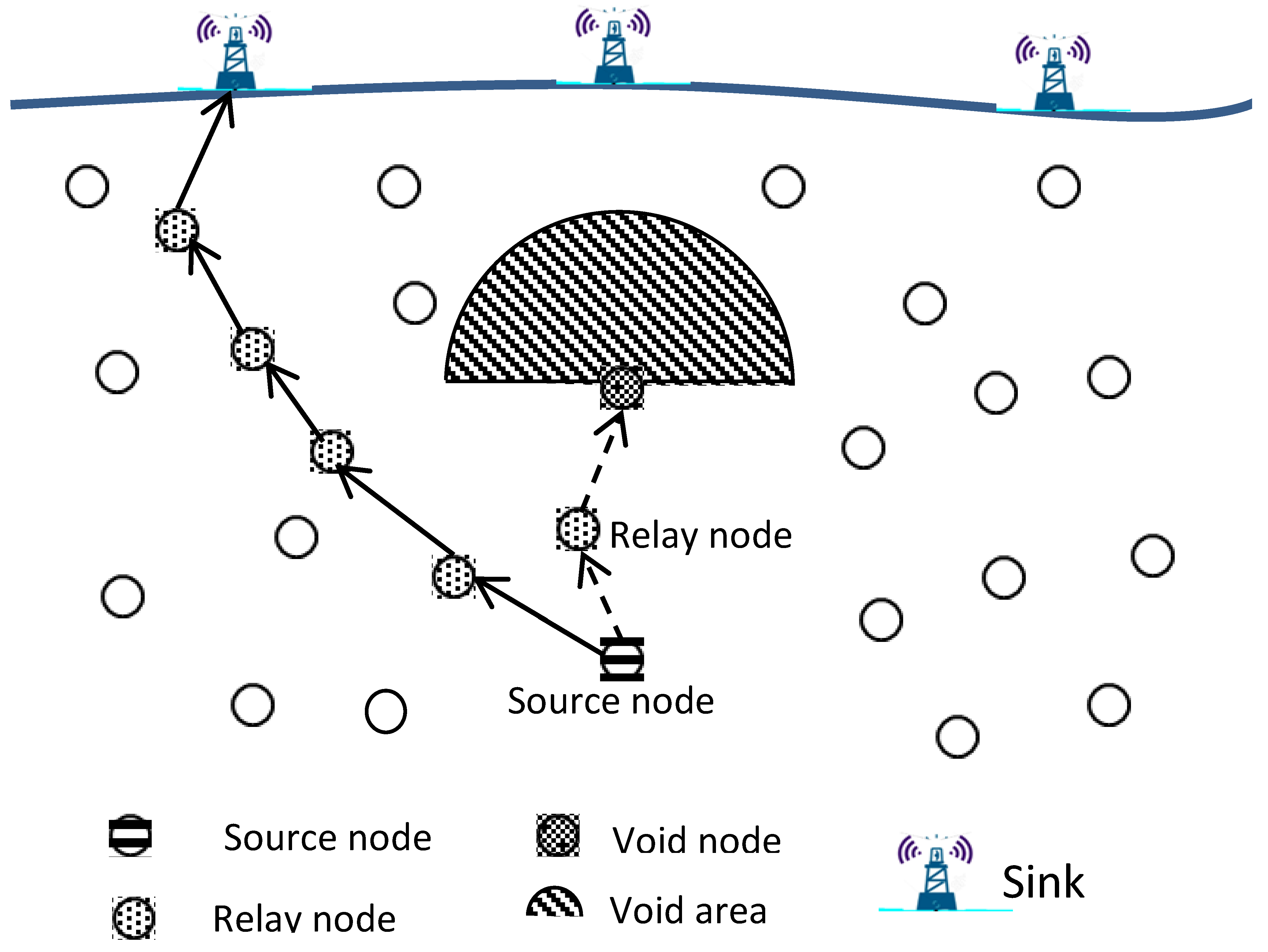
2.2. Void Area Problem in UWSNs
- Sparse topology deployment: Because underwater sensor nodes are expensive, it may not be possible to deploy enough of them to cover the area of interest. These sparse networks are prone to empty areas.
- Underwater sensors failure: Owing to the harshness and peculiarities of the underwater environment, it is more likely that the sensors would malfunction due to corrosion and fouling, which could result in a void area issue.
- Movement of the underwater sensor nodes: Water currents cause the underwater sensor nodes to move in both horizontal and vertical directions. Both node placements and the network topology will change because of this relocation, and a void area might be created.
- Temporary obstacles: Many living organisms are found in the underwater environment. The movement of organisms could interfere with the underwater sensor nodes’ ability to communicate. In addition, ships, boats, and other water-surface machinery might block the communication link between the network devices. As a result, void areas could be created.
- The acoustic channel characteristics: The underwater environment characteristics have an impact on the acoustic communication channel, changing the signal’s quality and strength at different water depths due to disturbed pressure, temperature, and salinity at varying water levels.
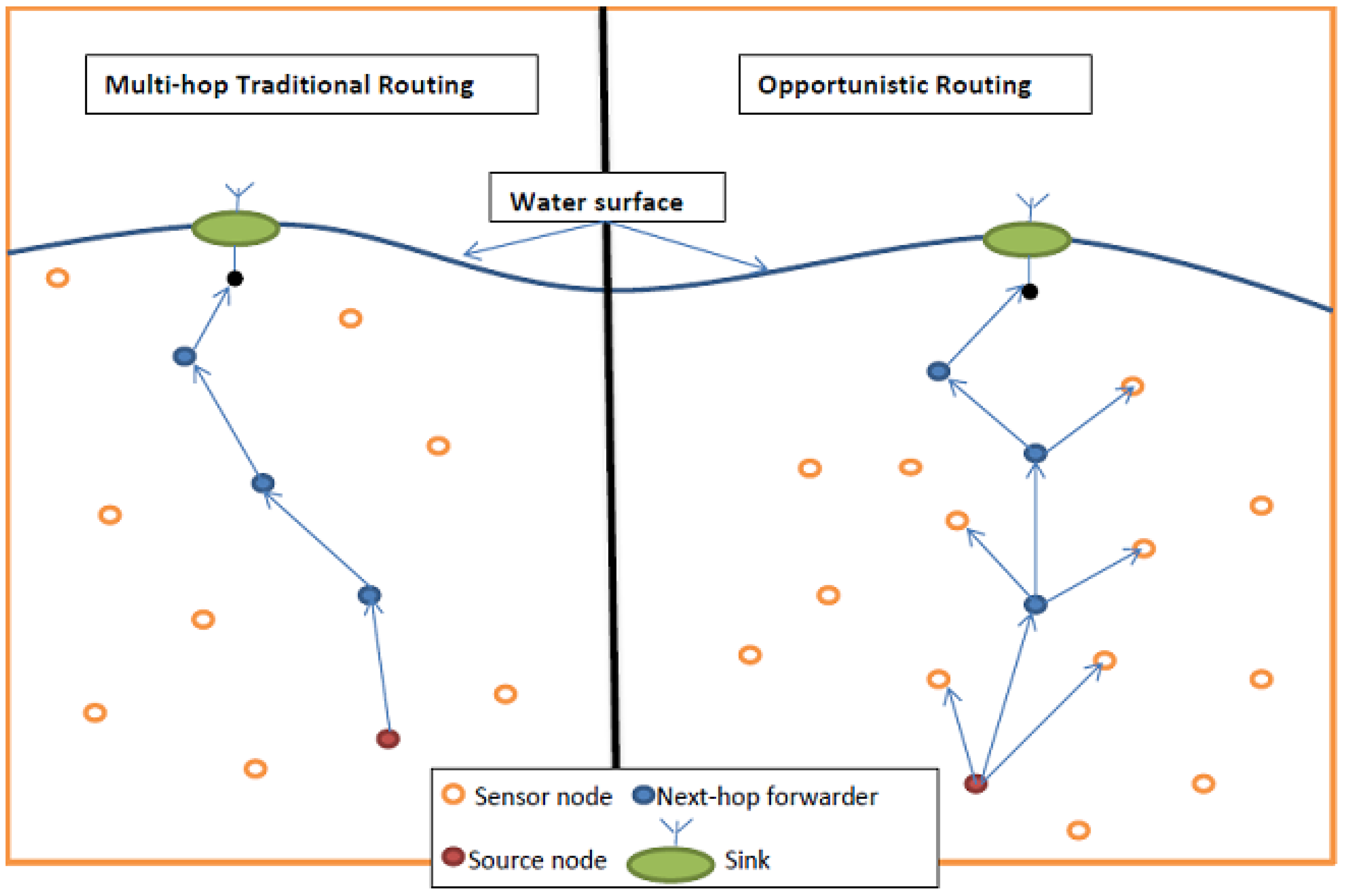
2.3. Opportunistic Routing
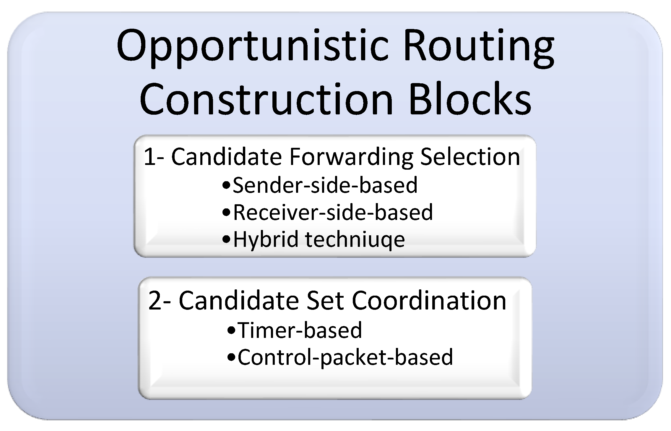
2.3.1. OR Construction Blocks
Candidate Forwarding Selection
- Sender-side-based candidate set selection: in this category, beacon messages between the nodes in the networks are used to exchange the information of the sensor nodes and make it available within their neighborhood. The current forwarder node, which has a data packet to transmit, will use this information to facilitate its mission to determine its next-hop forwarder candidate set.
- Receiver-side-based candidate set selection: in contrast to the first category, this one requires the neighbors to check the data packet’s header when they receive a data packet from the sender in order to identify which received nodes are eligible to be candidate nodes and which ones are not. In this category, each neighboring node is responsible for determining whether it will be included in the list of the potential next-hop forwarder candidate set or not.
- Hybrid candidate set selection: In this category, the next-hop forwarder candidate set is determined cooperatively by the current forwarder node, which has the data packet to transmit, and its neighbor nodes by exchanging their information.
Candidate Set Coordination
- Timer-based candidate set coordination: Each candidate node in this process has a holding time based on its priority. As a result, the candidate keeps the source’s received data packet in their possession for a while (the holding period). The remaining candidates will suppress their transmission if the highest-priority node successfully transmits the packet and if they get an indication during the waiting period. If not, the packet will begin to be forwarded by the node with the next highest priority when its holding time expires, and so on.
- Control packet-based candidate set coordination: The candidate nodes in this approach communicate with one another by exchanging control packets. Therefore, a candidate node responds to a packet with a brief control message. This control packet transmission is used to notify the currently active forwarder node that the packet has been successfully received. It also notifies the other low priority candidate nodes to pause their transmissions.
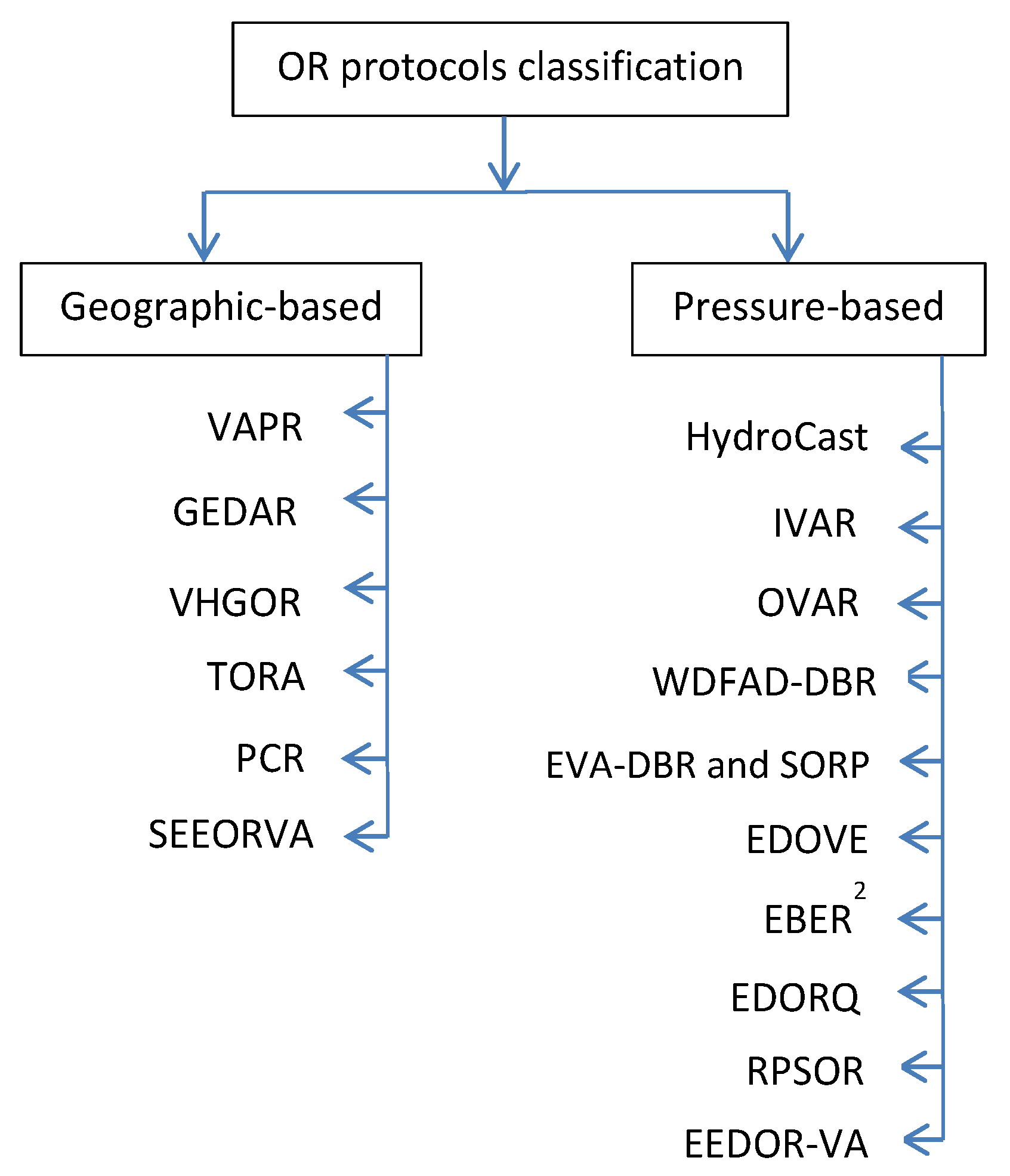
2.3.2. OR Classification
3. Review on Opportunistic Routing Void Avoidance Protocols for UWSNs
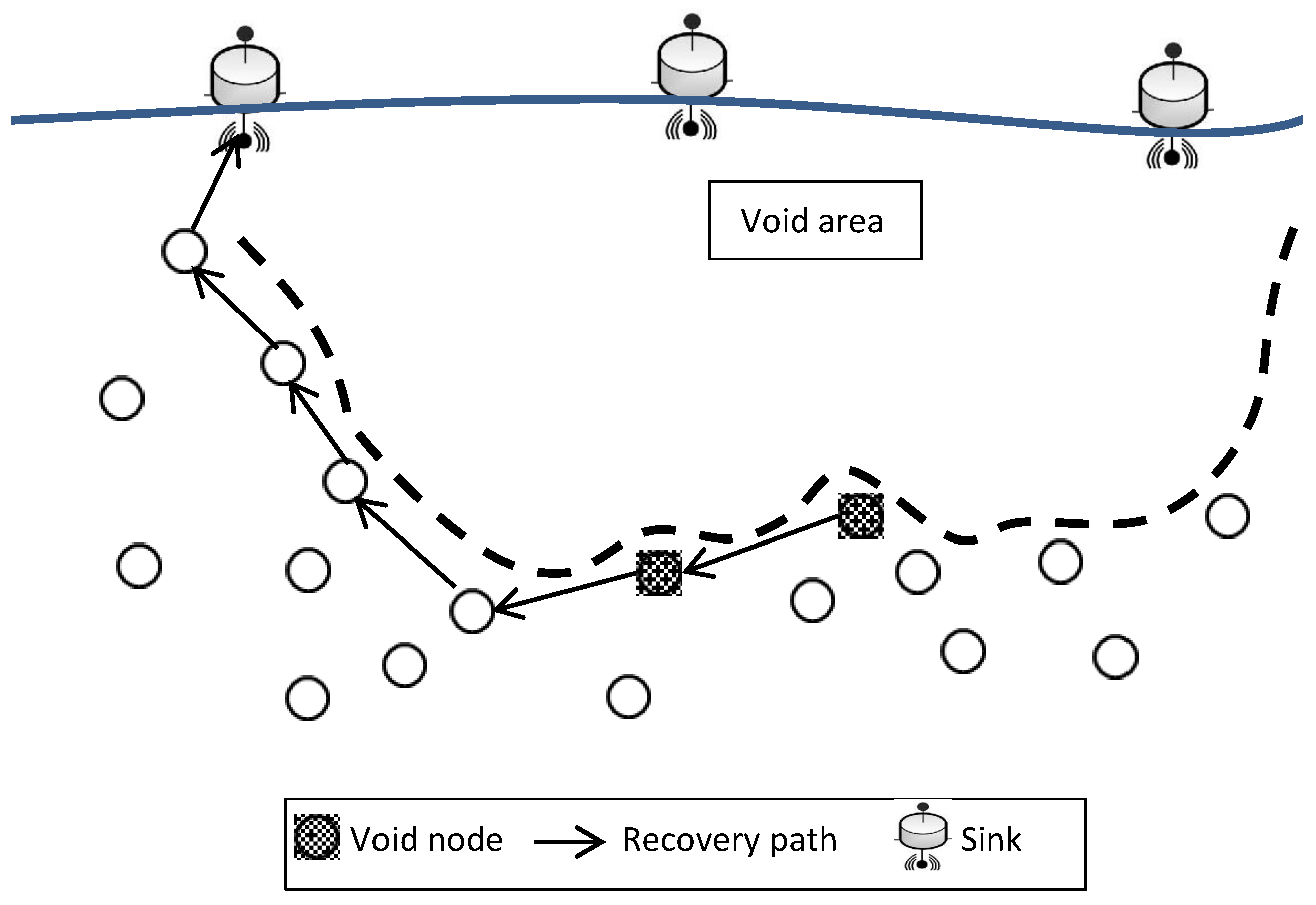
- Convex void handling: If the packet is stuck at the NCD node, VHGOR attempts to identify a different path to forward the same packet to the destination by removing the present forwarder and re-establishing the convex structure with remaining neighbors founded in the neighbor table (NT).
- Concave void handling or recovery mode: The void becomes concave when a packet gets trapped in a node without any neighbors with lower pressure levels, which means that its NT entry is empty. In order to reroute the packet along a different path to the destination, VHGOR manages the concave void by rerouting it down the recovery path, which runs from downward to upward. The previous sender chooses the subsequent NCD node from its NT to continue sending the same packet after receiving the packet from the concave empty node.
4. Comparison Study of OR Protocols for UWSNs
5. Open Issues and Challenges in UWSNs
- Energy efficiency: Due to the harsh underwater environment restrictions and limitations on recharging or replacing the deployed sensor node, energy efficiency is a major constraint that can restrict many applications from achieving their goals. The current focus of study is on energy conservation and routing process energy optimization. Future studies will continue to focus heavily on this topic.
- Channel utilization: effective and efficient channel usage is a significant area of investigation in UWSNs that has attracted a lot of attention; it has an effect on energy consumption and void areas that form easily in UWSNs. The channel must be used to its full potential to overcome its limitations, like interference, high error rates, continual sensor node mobility, and propagation latency.
- Void areas: Due to the reasons listed in Section 2.2, void areas result in more frequent packet drops, decreasing the network QoS. To ensure a high QoS for various UWSN applications and increase network reliability, more mechanisms to handle void areas and void communications effectively and establish trust for user apps are required.
- Security: A significant area of concern is the security of data exchanged between sensor nodes. The security of data is the most crucial issue in many UWSN applications, especially the military ones. In such applications, any information leak could lead to harmful effects and severe repercussions. To secure the connection between the sensor nodes in UWSNs as attacks and threats grow, investigations that consider security and privacy will be a continuing and extremely difficult effort.
6. Conclusions
Author Contributions
Funding
Institutional Review Board Statement
Informed Consent Statement
Data Availability Statement
Conflicts of Interest
Abbreviations
| ACKs | Acknowledgment messages |
| ADCs | Analog to Digital Converters |
| ADV | Advancement Distance |
| AUV | Autonomous Underwater Vehicle |
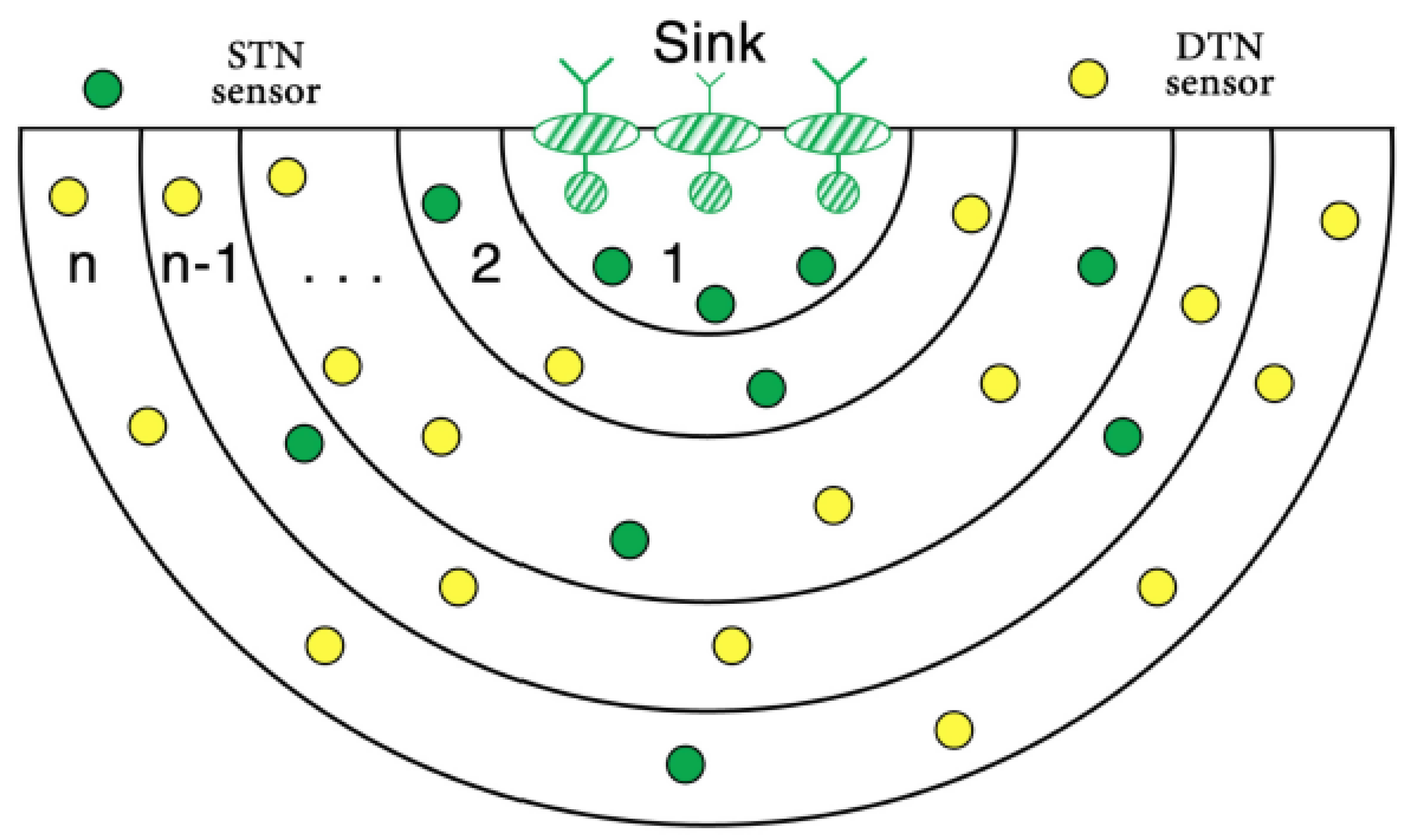
| DTN | Double Transmission Node |
| EBER2 | An Energy Balanced Efficient and Reliable Routing Protocol |
| EDORQ | Energy-efficient Depth-based Opportunistic Routing with Q-Learning |
| EDOVE | Energy and Depth variance-based Opportunistic Void avoidance |
| EEDOR-VA | Energy Efficient Depth-based Opportunistic Routing protocol |
| EVA-DBR | Energy-efficient and Void Avoidance Depth Based Routing |
| GEDAR | GEographic and opportunistic routing with Depth Adjustment-based topology control for communication Recovery |
| HCREP | Hop-Count Reply |
| HCREQ | Hop-Count Request |
| HydroCast | A Hydraulic Pressure Based Anycast Routing Protocol |
| IoUTs | Internet of Underwater Things |
| IVAR | An Inherently Void Avoidance Routing Protocol for Underwater Sensor Networks |
| OR | Opportunistic Routing |
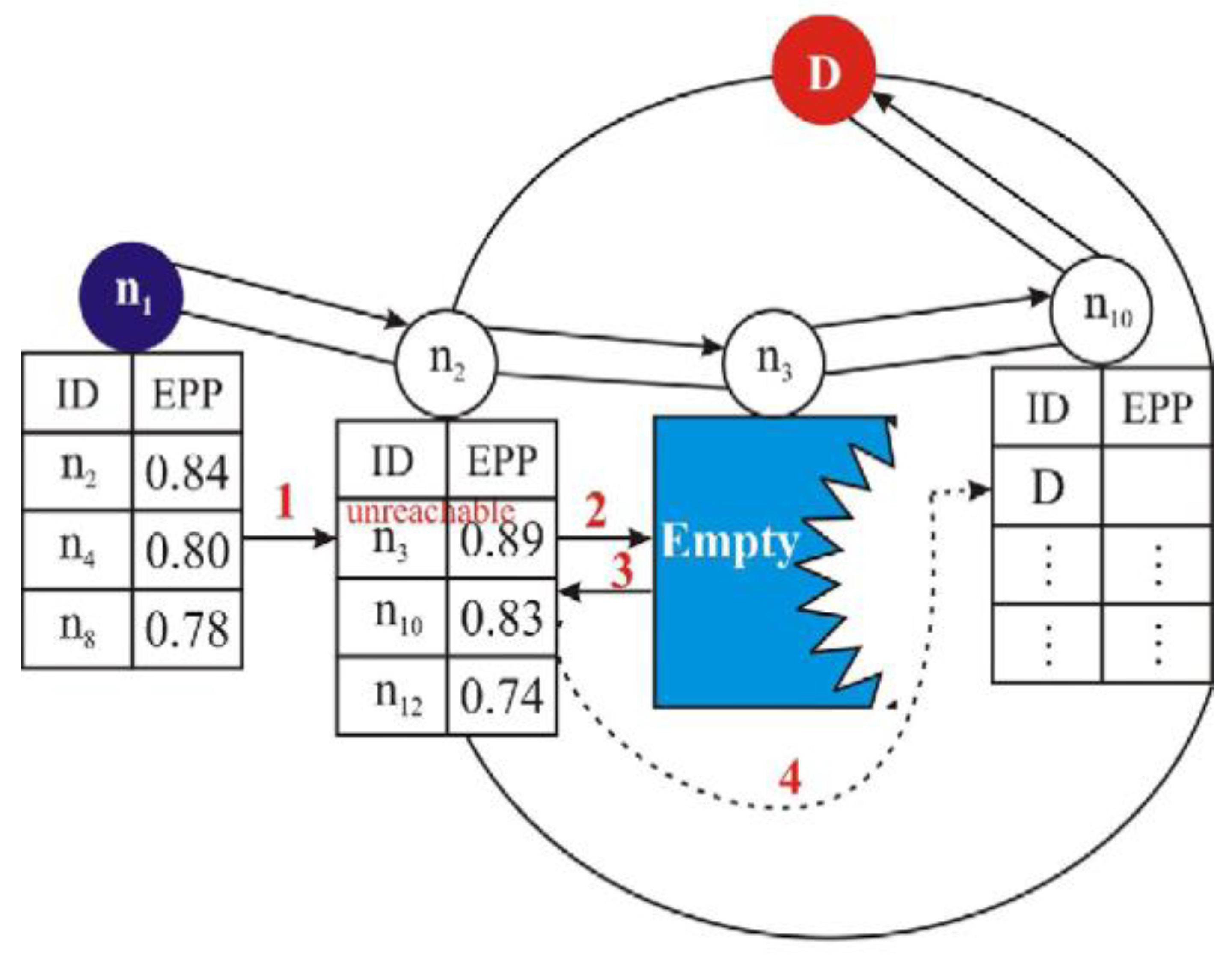
| OREPP | Opportunistic Routing based Expected Packet Progress |
| PCR | Power Control-based opportunistic Routing protocol |
| PDP | Packet Delivery Probability |
| QoS | Quality of Service |
| RPSOR | Reliable Path Selection and Opportunistic Routing |
| SEEORVA | Energy-Efficient Opportunistic Routing Protocol with Void Avoidance For Underwater Acoustic Sensor Networks |
| STN | Single Transmission Node |
| TORA | Totally Opportunistic Routing Algorithm |
| TWSNs | Terrestrial Wireless Sensor Networks |
| uw-sinks | underwater sinks |
| UWSNs | Underwater Wireless Sensor Networks |
| VAPR | Void-Aware Pressure Routing |
| VHGOR | Void Handling using Geo-Opportunistic Routing in underwater wireless sensor networks |
| WDFAD-DBR | Weighting Depth and Forwarding Area Division DBR routing protocol |
References
- Coutinho, R.W.; Boukerche, A.; Vieira, L.F.; Loureiro, A.A. Design Guidelines for Opportunistic Routing in Underwater Networks. IEEE Commun. Mag. 2016, 54, 40–48. [Google Scholar] [CrossRef]
- Shovon, I.I.; Shin, S. Survey on Multi-Path Routing Protocols of Underwater Wireless Sensor Networks: Advancement and Applications. Electronics 2022, 11, 3467. [Google Scholar] [CrossRef]
- Akyildiz, I.F.; Pompili, D.; Melodia, T. Underwater acoustic sensor networks: Research challenges. Ad Hoc Netw. 2005, 3, 257–279. [Google Scholar] [CrossRef]
- Allen, C.O. Wireless sensor network nodes: Security and deployment in the niger-delta oil and gas sector. Int. J. Netw. Secur. Its Appl. (IJNSA) 2011, 3, 68–79. [Google Scholar]
- Du, X.; Liu, X.; Su, Y. Underwater acoustic networks testbed for ecological monitoring of Qinghai Lake. In OCEANS 2016-Shanghai; IEEE: Piscataway, NJ, USA, 2016. [Google Scholar]
- Freitag, L.; Grund, M.; Von Alt, C.; Stokey, R.; Austin, T. A shallow water acoustic network for mine countermeasures operations with autonomous underwater vehicles. In Proceedings of the Undersea Defence Technology (UDT), Amsterdam, The Netherlands, 21–23 June 2005; pp. 1–6. [Google Scholar]
- Henry, N.F.; Henry, O.N. Wireless sensor networks based pipeline vandalisation and oil spillage monitoring and detection: Main benefits for nigeria oil and gas sectors. SIJ Trans. Comput. Sci. Eng. Its Appl. 2015, 3, 1–6. [Google Scholar]
- Khan, A.; Jenkins, L. Undersea wireless sensor network for ocean pollution prevention. In Proceedings of the 2008 3rd International Conference on Communication Systems Software and Middleware and Workshops (COMSWARE’08), Bangalore, India, 6–10 January 2008. [Google Scholar]
- Kumar, O.; Priyadarshini, P. Underwater acoustic sensor network for early warning generation. In Proceedings of the 2012 Oceans, Hampton Roads, VA, USA, 14–19 October 2012; IEEE: Piscataway, NJ, USA, 2012; pp. 1–6. [Google Scholar]
- Lloret, J.; Sendra, S.; Garcia, M.; Lloret, G. Group-based underwater wireless sensor network for marine fish farms. In Proceedings of the 2011 IEEE GLOBECOM Workshops (GC Wkshps), Houston, TX, USA, 5–9 December 2011; IEEE: Piscataway, NJ, USA, 2011. [Google Scholar]
- Mohamed, N.; Jawhar, I.; Al-Jaroodi, J.; Zhang, L. Sensor network architectures for monitoring underwater pipelines. Sensors 2011, 11, 10738–10764. [Google Scholar] [CrossRef] [PubMed]
- Casey, K.; Lim, A.; Dozier, G. A sensor network architecture for tsunami detection and response. Int. J. Distrib. Sens. Netw. 2008, 4, 27–42. [Google Scholar] [CrossRef]
- Alsulami, M.; Elfouly, R.; Ammar, R. Underwater Wireless Sensor Networks: A Review. In Proceedings of the 11th International Conference on Sensor Networks (SENSORNETS 2022), Virtual Event, 7–8 February 2022. [Google Scholar]
- Garg, P.; Waraich, S. Parametric Comparative Analysis of Underwater Wireless Sensor Networks Routing Protocols. Int. J. Comput. Appl. 2015, 116, 0975–8887. [Google Scholar] [CrossRef]
- Khasawneh, A.; Abd Latiff, M.S.B.; Kaiwartya, O.; Chizari, H. Next forwarding node selection in underwater wireless sensor networks (UWSNs): Techniques and Challenges. Information 2017, 8, 3. [Google Scholar] [CrossRef]
- Wosowei, J.; Shastry, C. Underwater Wireless Sensor Networks: Applications and Challenges in Offshore Operations. Int. J. Curr. Adv. Res. 2021, 10, 23729–23733. [Google Scholar]
- Mittal, S.; Kumar, R.K.R. Different Communication Technologies and Challenges for Implementing UWSN. In Proceedings of the 2021 2nd International Conference on Advances in Computing, Communication, Embedded and Secure Systems (ACCESS), Ernakulam, India, 2–4 September 2021. [Google Scholar]
- Nayyar, A.; Puri, V.; Le, D.N. Comprehensive Analysis of Routing Protocols Surrounding Underwater Sensor Networks (UWSNs). In Data Management, Analytics and Innovation; Springer: Singapore, 2019; pp. 435–450. [Google Scholar]
- Solayappan, A.; Frej, M.B.H.; Rajan, S.N. Energy Efficient Routing Protocols and Efficient Bandwidth Techniques in Underwater Wireless Sensor Networks—A Survey. In Proceedings of the 2017 IEEE Long Island Systems, Applications and Technology Conference (LISAT), Farmingdale, NY, USA, 5 May 2017. [Google Scholar]
- Yee, L.; Mehmood, S.; Almogren, A.; Ali, I.; Anisi, M.H. Improving the performance of opportunistic routing using min-max range and optimum energy level for relay node selection in wireless sensor networks. PeerJ Comput. Sci. 2020, 6, e326. [Google Scholar] [CrossRef] [PubMed]
- Chen, D.; Varshney, P.K. A survey of void handling techniques for geographic routing in wireless networks. IEEE Commun. Surv. Tutor. 2007, 9, 50–67. [Google Scholar] [CrossRef]
- Kavar, J.M.; Wandra, K.H. Survey paper on Underwater Wireless Sensor Network. Int. J. Adv. Res. Electr. Electron. Instrum. Eng. 2014, 3, 7294–7300. [Google Scholar]
- Kiran, J.S.; Sunitha, L.; Rao, D.K.; Sooram, A. Review on Underwater Sensor Networks: Applications, Research Challenges and Time Synchronization. Int. J. Eng. Res. Technol. 2015, 4, 1329–1332. [Google Scholar]
- Erol-Kantarci, M.; Mouftah, H.T.; Oktug, S. A Survey of Architectures and Localization Techniques for Underwater Acoustic Sensor Networks. IEEE Commun. Surv. Tutor. 2011, 13, 487–502. [Google Scholar] [CrossRef]
- Darehshoorzadeh, A.; Boukerche, A. Underwater Sensor Networks: A New Challenge for Opportunistic Routing Protocols. IEEE Commun. Mag. 2015, 53, 98–107. [Google Scholar] [CrossRef]
- Luo, J.; Fan, L.; Wu, S.; Yan, X. Research on Localization Algorithms Based on Acoustic Communication for Underwater Sensor Networks. Sensors 2018, 18, 67. [Google Scholar] [CrossRef]
- Ayaz, M.; Baig, I.; Abdullah, A.; Faye, I. A Survey on Routing Techniques in Underwater Wireless Sensor Networks. J. Netw. Comput. Appl. 2011, 34, 1908–1927. [Google Scholar] [CrossRef]
- Lu, Q.; Liu, F.; Zhang, Y.; Jiang, S. Routing Protocols for Underwater Acoustic Sensor Networks: A Survey from an Application Perspective. In Advances in Underwater Acoustics; InTech: London, UK, 2017. [Google Scholar]
- Islam, T.; Lee, Y.K. A Comprehensive Survey of Recent Routing Protocols for Underwater Acoustic Sensor Networks. Sensors 2019, 19, 4256. [Google Scholar] [CrossRef]
- Jadhav, P.; Satao, R. A Survey on Opportunistic Routing Protocols for Wireless Sensor Networks. Procedia Comput. Sci. 2016, 79, 603–609. [Google Scholar] [CrossRef]
- Khan, H.; Hassan, S.A.; Jung, H. On Underwater Wireless Sensor Networks Routing Protocols: A Review. IEEE Sens. J. 2020, 20, 10371–10386. [Google Scholar] [CrossRef]
- Felemban, E.; Shaikh, F.K.; Qureshi, U.M.; Sheikh, A.A.; Qaisar, S.B. Underwater Sensor Network Applications: A Comprehensive Survey. Int. J. Distrib. Sens. Netw. 2015, 11, 14. [Google Scholar] [CrossRef]
- Akyildiz, I.F.; Pompili, D.; Melodia, T. Challenges for Efficient Communication in Underwater Acoustic Sensor Networks. ACM Sigbed Rev. 2004, 1, 3–8. [Google Scholar] [CrossRef]
- Jain, U.; Hussain, M. UnderwaterWireless Sensor Networks. In Handbook of Computer Networks and Cyber Security; Springer: Cham, Switzerland, 2020; pp. 227–245. [Google Scholar]
- Awan, K.M.; Shah, P.A.; Iqbal, K.; Gillani, S.; Ahmad, W.; Nam, Y. Underwater Wireless Sensor Networks: A Review of Recent Issues and Challenges. Wirel. Commun. Mob. Comput. 2019, 2019, 20. [Google Scholar] [CrossRef]
- Mhemed, R. Energy Efficient and Void Avoiding Routing Protocols for Underwater Wireless Sensor Networks. Ph.D. Thesis, Dalhousie University, Halifax, NS, Canada, 2022. [Google Scholar]
- Khalid, M.; Ullah, Z.; Ahmad, N.; Arshad, M.; Jan, B.; Cao, Y.; Adnan, A. A Survey of Routing Issues and Associated Protocols in Underwater Wireless Sensor Networks. J. Sens. 2017, 2017, 7539751. [Google Scholar] [CrossRef]
- Vieira, L.F.M. Performance and Trade-off of Opportunistic Routing in Underwater Networks. In Proceedings of the IEEE Wireless Communications and Networking Conference: Mobile and Wireless Networks, Paris, France, 1–4 April 2012. [Google Scholar]
- Jiang, J.; Han, G.; Guo, H.; Shu, L.; Rodrigues, J.J. Geographic multipath routing based on geospatial division in duty-cycled underwater wireless sensor networks. J. Netw. Comput. Appl. 2016, 59, 4–13. [Google Scholar] [CrossRef]
- Liu, H.; Zhang, B.; Mouftah, H.T.; Shen, X.; Ma, J. Opportunistic routing for wireless ad hoc and sensor networks: Present and future directions. IEEE Commun. Mag. 2009, 47, 103–109. [Google Scholar] [CrossRef]
- Fang, Q.; Gao, J.; Guibas, L.J. Locating and Bypassing Routing Holes in Sensor Networks. Mob. Netw. Appl. 2006, 11, 187–200. [Google Scholar] [CrossRef]
- Al-Dharrab, S.; Uysal, M.; Duman, T.M. Cooperative Underwater Acoustic Communications. IEEE Commun. Mag. 2013, 51, 146–153. [Google Scholar] [CrossRef]
- Lee, U.; Wang, P.; Noh, Y.; Vieira, L.F.; Gerla, M.; Cui, J.H. Pressure routing for underwater sensor networks. In Proceedings of the 2010 Proceedings IEEE INFOCOM, San Diego, CA, USA, 14–19 March 2010. [Google Scholar]
- Noh, Y.; Lee, U.; Wang, P.; Choi, B.S.C.; Gerla, M. VAPR: Void-Aware Pressure Routing for Underwater Sensor Networks. IEEE Trans. Mob. Comput. 2013, 12, 895–908. [Google Scholar] [CrossRef]
- Coutinho, R.W.; Boukerche, A.; Vieira, L.F.; Loureiro, A.A. Geographic and Opportunistic Routing for Underwater Sensor Networks. IEEE Trans. Comput. 2016, 65, 548–561. [Google Scholar] [CrossRef]
- Ghoreyshi, S.M.; Shahrabi, A.; Boutaleb, T. An Inherently Void Avoidance Routing Protocol for Underwater Sensor Networks. In Proceedings of the 2015 International Symposium on Wireless Communication Systems (ISWCS), Brussels, Belgium, 25–28 August 2015. [Google Scholar] [CrossRef]
- Ghoreyshi, S.M.; Shahrabi, A.; Boutaleb, T. A Novel Cooperative Opportunistic Routing Scheme for Underwater Sensor Networks. Sensors 2016, 16, 297. [Google Scholar] [CrossRef]
- Kanthimathi, N. Void handling using Geo-Opportunistic Routing in underwater wireless sensor networks. Comput. Electr. Eng. 2017, 64, 365–379. [Google Scholar] [CrossRef]
- Yu, H.; Yao, N.; Wang, T.; Li, G.; Gao, Z.; Tan, G. WDFAD-DBR:Weighting depth and forwarding area division DBR routing protocol for UASNs. Ad Hoc Netw. 2015, 37, 256–282. [Google Scholar] [CrossRef]
- Ghoreyshi, S.M.; Shahrabi, A.; Boutaleb, T. An Underwater Routing Protocol with Void Detection and Bypassing Capability. In Proceedings of the 2017 IEEE 31st International Conference on Advanced Information Networking and Applications, Taipei, Taiwan, 27–29 March 2017. [Google Scholar]
- Ghoreyshi, S.M.; Shahrabi, A.; Boutaleb, T. A Stateless Opportunistic Routing Protocol for Underwater Sensor Networks. Wirel. Commun. Mob. Comput. 2018, 2018, 18. [Google Scholar] [CrossRef]
- Bouk, S.H.; Ahmed, S.H.; Park, K.J.; Eun, Y. EDOVE: Energy and Depth Variance-Based Opportunistic Void Avoidance Scheme forUnderwater Acoustic Sensor Networks. Sensors 2017, 17, 2212. [Google Scholar] [CrossRef]
- Rahman, Z.; Hashim, F.; Rasid, M.F.A.; Othman, M. Totally opportunistic routing algorithm (TORA) for underwater wireless sensor network. PLoS ONE 2018, 13, 1–28. [Google Scholar] [CrossRef] [PubMed]
- Wadud, Z.; Ismail, M.; Qazi, A.B.; Khan, F.A.; Derhab, A.; Ahmad, I.; Ahmad, A.M. An Energy Balanced Efficient and Reliable Routing Protocol for Underwater Wireless Sensor Networks. IEEE Access 2019, 7, 175980–175999. [Google Scholar] [CrossRef]
- Lu, Y.; He, R.; Chen, X.; Lin, B.; Yu, C. Energy-Efficient Depth-Based Opportunistic Routing with Q-Learning for Underwater Wireless Sensor Networks. Sensors 2020, 20, 1025. [Google Scholar] [CrossRef]
- Ismail, M.; Islam, M.; Ahmad, I.; Khan, F.A.; Qazi, A.B.; Khan, Z.H.; Wadud, Z.; Al-Rakhami, M. Reliable Path Selection and Opportunistic Routing Protocol for Underwater Wireless Sensor Networks. IEEE Access 2020, 8, 100346–100364. [Google Scholar] [CrossRef]
- Coutinho, R.W.; Boukerche, A.; Loureiro, A.A. A novel opportunistic power controlled routing protocol for internet of underwater things. Comput. Commun. 2020, 150, 72–82. [Google Scholar] [CrossRef]
- Menon, V.; Midhunchakkaravarthy, D.; John, S.; Jacob, S.; Mukherjee, A. A secure and energy-efficient opportunistic routing protocol with void avoidance for underwater acoustic sensor networks. Turk. J. Electr. Eng. Comput. Sci. 2020, 28, 2303–2315. [Google Scholar] [CrossRef]
- Mhemed, R.; Comeau, F.; Phillips, W.; Aslam, N. Void Avoidance Opportunistic Routing Protocol for Underwater Wireless Sensor Networks. Sensors 2021, 21, 1942. [Google Scholar] [CrossRef] [PubMed]


| Protocol | Category | Forwarding Set Selection Category | Sink(s) | Requirements | Knowledge Required/Maintained | Advantage | Disadvantage |
|---|---|---|---|---|---|---|---|
| HydroCast [43] | Pressure-based routing | Sender-side | Multi-sink | Nodes with special H/W | 2-hop connectivity and the pairwise distances for the neighboring nodes |
|
|
| VAPR [44] | Geography-based routing | Sender-side | Multi-sink | SEA Swarm nodes | next-hop direction and hop distanceinformation at each node |
|
|
| GEDAR [45] | Geography-based routing | Sender-side | Multi-sink | Nodes with special H/W | Position information of its own, neighbors and sink |
|
|
| IVAR [46] | Pressure-based routing | Receiver-side | Single-sink FIXED | Relay nodes and anchored nodes | Own depth, 1-hop neighbors and sink location |
|
|
| OVAR [47] | Pressure-based routing | Sender-side | Single-sink FIXED | Relay nodes and anchored nodes | Own depth, 1-hop neighbors and sink location info. |
|
|
| VHGOR [48] | Geography- based routing | Sender-side | Single-sink | Geo. location is available | Own location/ neighboring table |
|
|
| WDFAD-DBR [49] | Pressure-based routing | Receiver-side | Multi-sinks | Anchored, relay and sink nodes. | Owen depth, 1-hop neighbor’s information and 2-hop neighbor’s depth. |
|
|
| EVA-DBR [50] andSORP [51] | Pressure-based routing | Sender-side | Multi-sinks | Anchored, relay and sink nodes. | Owen depth, 1-hop neighbor’s information and 2-hop neighbor’s depth. |
|
|
| EDOVE [52] | Pressure-based routing | Receiver-side | Multi-sinks | Anchored, relay and sink nodes. | Owen depth, 1-hop neighbor’s information and 2-hop neighbor’s depth. |
|
|
| TORA [53] | Geography- based routing | Receiver-based | Multi-sinks | Sink nodes and ordinary nodes. | Sinks and ordinary position information. |
|
|
| EBER2 [54] | Pressure-based routing | Sender-side | Multi-sink | Anchored, relay and underwater sink nodes. | Two-hop Potential Forwarding nodes. |
|
|
| EDORQ [55] | Pressure-based routing | Receiver-side | Multi-sink | Relay nodes and anchored nodes | Own depth, 1-hop neighbors and sink location |
|
|
| RPSOR [56] | Pressure-based routing | Receiver-side | Multi-sink | Mobile sinks, relay nodes and anchored nodes | Owen depth, 1-hop neighbor’s information and 2-hop neighbor’s depth |
|
|
| PCR [57] | Geography-based routing | Sender-side | Multi-sink | Nodes with power control mechanism. | Position information of its own, neighbors and sinks |
|
|
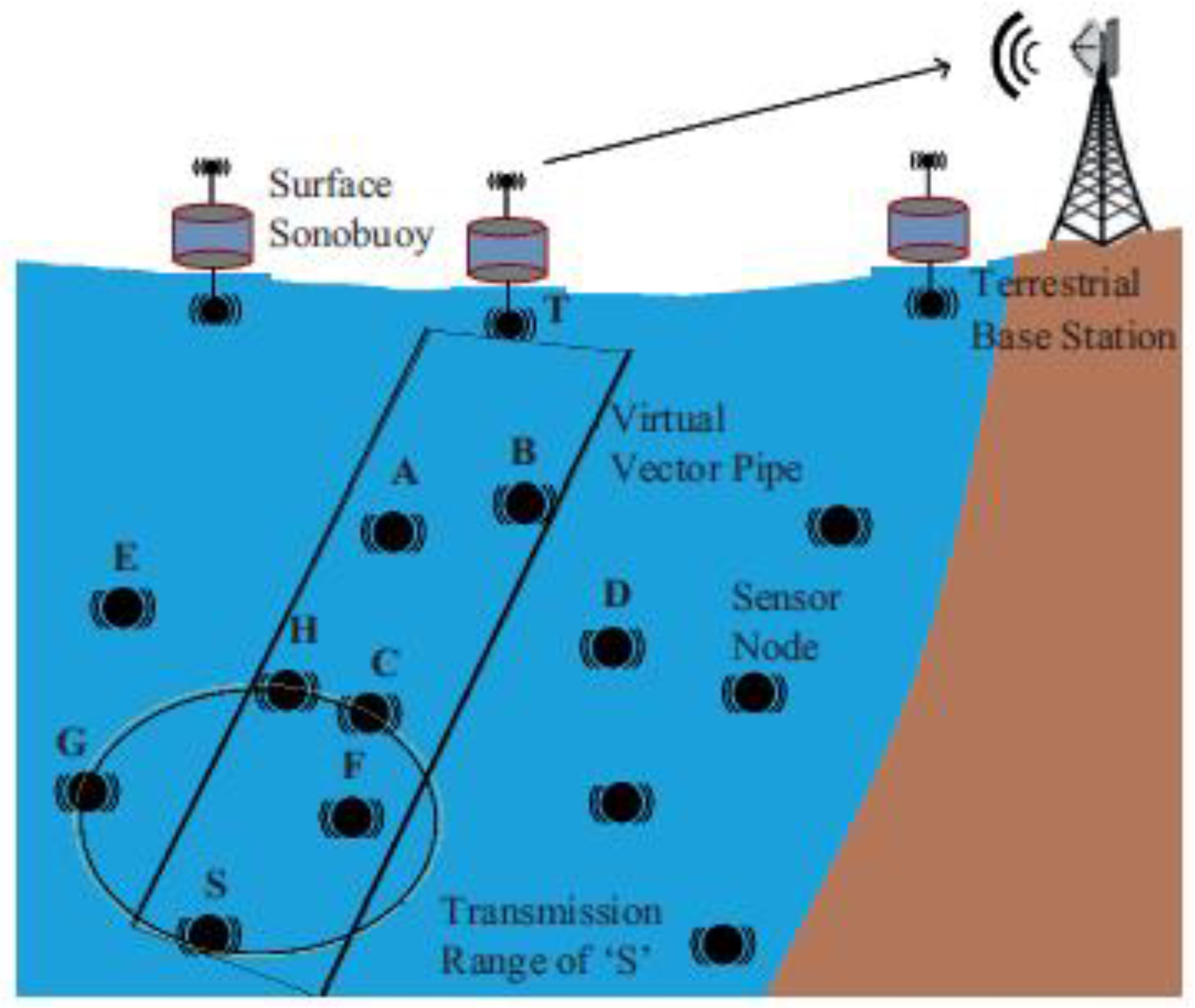
| SEEORVA [58] | Geography-based routing | Sender-side | Multi-sink | Underwater sensor nodes (source/ relay). | Nodes located in the virtual vector pipe between source node and sink |
|
|
| EEDOR-VA [59] | Pressure-based routing | Hybrid technique | Multi-sink | Nodes with special H/W (depth sensor). | Nodes’ hop count and depth.The previous HCREQ sender to unicast the HCREP to that node. |
|
|
Publisher’s Note: MDPI stays neutral with regard to jurisdictional claims in published maps and institutional affiliations. |
© 2022 by the authors. Licensee MDPI, Basel, Switzerland. This article is an open access article distributed under the terms and conditions of the Creative Commons Attribution (CC BY) license (https://creativecommons.org/licenses/by/4.0/).
Share and Cite
Mhemed, R.; Phillips, W.; Comeau, F.; Aslam, N. Void Avoiding Opportunistic Routing Protocols for Underwater Wireless Sensor Networks: A Survey. Sensors 2022, 22, 9525. https://doi.org/10.3390/s22239525
Mhemed R, Phillips W, Comeau F, Aslam N. Void Avoiding Opportunistic Routing Protocols for Underwater Wireless Sensor Networks: A Survey. Sensors. 2022; 22(23):9525. https://doi.org/10.3390/s22239525
Chicago/Turabian StyleMhemed, Rogaia, William Phillips, Frank Comeau, and Nauman Aslam. 2022. "Void Avoiding Opportunistic Routing Protocols for Underwater Wireless Sensor Networks: A Survey" Sensors 22, no. 23: 9525. https://doi.org/10.3390/s22239525
APA StyleMhemed, R., Phillips, W., Comeau, F., & Aslam, N. (2022). Void Avoiding Opportunistic Routing Protocols for Underwater Wireless Sensor Networks: A Survey. Sensors, 22(23), 9525. https://doi.org/10.3390/s22239525