Abstract
A film bulk acoustic resonator (FBAR), based on a polymer air cavity, is presented. The polymer reflective layer on the polymer air cavity can serve both as the reflective layer and the function layer for inducing the high-order mode resonance. With the aluminum nitride as the piezoelectric layer, the resonance frequency of the FBAR can reach 6.360 GHz, based on the finite element method. The product of the corresponding frequency and the quality factor, f × Q is more than 2 × 10¹³. This design model provides a good solution for the high-frequency filters and high-sensitivity sensor designs.
1. Introduction
The popularization of fifth-generation communication equipment and the development of the internet of things has made the internet of everything possible, and these are inseparable from bulk acoustic wave (BAW)/surface acoustic wave (SAW) resonators. Due to the structural limitations of the SAW resonator, the higher the operating frequency, the thinner the interdigitated electrodes [1], and the thinner electrodes are difficult to withstand high frequency and power. The BAW filters are more frequently used in high-frequency communication and sensing because of their higher power tolerance. The BAW filters are divided into film bulk acoustic resonator (FBARs) [2,3,4], solidly mounted resonators (SMRs) [5,6], and laterally-excited bulk-wave resonators (XBARs) [7,8,9], based on the structure difference. At present, the piezoelectric film materials used in the BAW resonators mainly include aluminum nitride, zinc oxide, and PZT. Compared with the polycrystalline piezoelectric crystals, the single crystal piezoelectric crystals do not cause the scattering of acoustic waves inside the piezoelectric crystals, which helps to increase the speed of the acoustic wave. Growing high-performance piezoelectric films is key to the BAW fabrication, the common methods are physical vapor deposition (PVD) and chemical vapor deposition (CVD) [10,11]. For the resonator, due to the design deviation, the BAWs propagating in the film are accompanied by many parasitic modes, while coupling-out spurious modes often affect the signal-to-noise ratio of the filtered signal.
Currently. the known resonant modes of the FBAR include three modes: TE, TS, and E: (1) TE-FBAR is the earliest developed and the most widely used type on the market. Its c-axis is along the normal direction of the film plane (the thickness direction). It is mainly used in filters, duplexers, and oscillators. It is used in radio frequency devices such as communication systems [12,13]. (2) The FBAR (TS-FBAR) with the basic thickness-shear (TS) as the resonance mode, needs a lining process to make the piezoelectricity during the material processing. The axis forms an inclination angle with the excitation electric field in the limit direction of the piezoelectric thin acid circuit, which excites the vibration response dominated by the TS mode. The TS-FBAR can maintain a high-quality factor when in contact with liquid and is usually used as a sensor in liquid or for biochemical information detection [14,15,16,17]. (3) The FBAR with in-plane stretching (E) as the resonance mode is usually called a contour-mode FBAR, which is also realized by tilting the c-axis of the piezoelectric film. Its main feature is that the resonant frequency of the device is greatly affected by the lateral size of the electrode, so it has inherent advantages in the integrated application of the device [18,19,20]. In recent years, more and more researchers have begun to study higher frequency resonators, based on the parasitic modes and higher-order resonances [21,22,23]. Regardless of the modes, they prevent acoustic waves from leaking into the substrate.
Here, a new FBAR design, based on a polymer air cavity is presented. The polymer reflective layer of the cavity serves not only as the high reflectivity layer of the FBAR but also as the function layer for exciting the high order mode resonance. The results show that the polymer reflective layer in the FBAR has a stronger resonance on both sides of the fundamental mode than that of the traditional FBAR. With the aluminum nitride as the piezoelectric layer, the resonance frequency of the FBAR can reach 6.360 GHz. The product of the corresponding frequency and the quality factor, f × Q is more than 2 × 10¹³. This design simplifies the fabrication process of the FBAR since a simple photolithography process can create this polymer cavity and avoid the complicated etching process of the traditional air cavity. Moreover, this design introduces the new characteristics of the FBAR. It is expected to have practical applications in the FBAR based filters and sensors.
2. Principle of the Polymer-FBAR
In recent years, researchers have proposed many different simulation analysis methods, such as the Mason and Butterworth Van Dyke one-dimensional simulation, and the simulation results are consistent with the experimental results [24,25].Therefore, it has become one of the most popular simulation methods. Nevertheless, the one-dimensional modeling simulation is not enough to pay attention to the stray mode in the simulation of the FBAR resonator. The acoustic wave propagates inside the FBAR, and the electromechanical coupling in the transverse and longitudinal directions exists at the same time, so it is necessary to carry out a two-dimensional finite element simulation of the FBAR resonator. Multiphysics systems can be represented by the boundary conditions and a set of equations. The stress equation of the motion can be expressed as [26]:
where Tij is the stress matrix, ρ is the density of the piezoelectric materials, and uj is displacement. The electrostatic Gaussian equation can be expressed as [27]:
The following stress-charge equations describes the electrostrictive behavior of the piezoelectric materials and it can be solved using simulation software. These equations are one of many forms that describe the inverse piezoelectric effect and the direct piezoelectric effect [28,29,30,31],
where cijkl is the elastic constant matrix, ekij is the piezoelectric constant matrix, ekij is the transpose of eikl, ε is the dielectric constant matrix, S is the strain, E is the electric field, and i, j, k, l are tensor indices.
The direct analysis of the results for the multiphysics systems is quite difficult. The finite element method can solve the multidimensional complex systems by using sophisticated approximation techniques for partial differential equations and discretizing the geometry of the system [32,33]. COMSOL® Multiphysics 5.6 (Comsol Multiphysics GmbH, Göttingen, Germany) is an important tool for solving such complex systems.
The piezoelectric conversion efficiency is usually described by the electromechanical coupling coefficient, but the difference between the electromechanical coupling coefficient K2 and the effective electromechanical coupling coefficient Kteff2 should be noted. K2 is the electromechanical coupling coefficient of the piezoelectric material, which is the intrinsic characteristic of the material, and Kteff2 is the effective electromechanical coupling coefficient of the resonator, which is not only related to the piezoelectric material, but also related to various resonator designs, such as film thickness, film material, and resonator structure. The electromechanical coupling coefficient K2 of the material can be obtained from the blew formula:
where fr is the resonant frequency and fa is the anti-resonant frequency [34,35,36]. The FBAR devices can use the piezoelectric effect to generate the mechanical resonance under the action of an input electrical signal, and correspondingly, the mechanical resonance can also be converted into an electrical signal output.
Figure 1 shows our proposed polymer FBAR 3D model. It has six parts, including the substrate, the polymer air cavity, the support layer, the bottom electrode layer, the piezoelectric layer, and the top electrode layer.
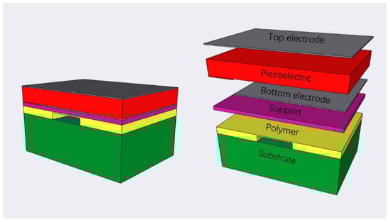
Figure 1.
3D model of the FBAR resonator.
The reflectance formula for the FBAR structure can be given by:
where C is the reflection coefficient, Z1 is the characteristic acoustic impedance of the support layer, and Z2 is the characteristic acoustic impedance of the polymer [37]. The characteristic acoustic impedance of a material is equal to the product of the density of the material and the velocity of the acoustic wave of the material. The characteristic acoustic impedance of the bottom electrode and the support layer is large while that of the characteristic acoustic impedance of the reflective polymer layer is small, resulting in a large reflection at the interface of the polymer support layer (C > 90%) [38]. Thin polymer layers cannot withstand strong stress, adding a silicon nitride support layer enhances the mechanical stability of the polymer FBAR [39,40,41].
A simulation analysis is performed by the finite element method (FEM) supported by COMSOL® Multiphysics 5.6 software. The proposed model of the polymer FBAR in the finite element simulation environment is shown in Figure 2, and the 3 μm perfectly matched layers (PML) on both sides and the bottom of the substrate are adopted. The bottom of the substrate is set as a fixed constraint, the drive voltage or power is applied to the top electrode and to the ground on the bottom electrode, and the frequency domain is used to calculate the impedance spectrum and reflection coefficient of the polymer FBAR.
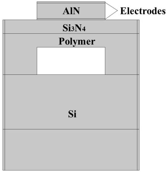
Figure 2.
Polymer-FBAR finite element simulation model.
In the finite element simulation environment, the traditional FBAR model and the polymer-FBAR model are established, respectively. The traditional FBAR has a silicon based air cavity while the proposed FBAR has a polymer air cavity. All parameters are the same except for the polymer layer for comparing the performance difference between the traditional FBAR and polymer-FBAR, from their results.
As shown in Figure 3, the traditional FBAR has only one resonance peak while two strong resonance peaks on both sides of the resonance peak of the traditional cavity FBAR are induced, for the polymer FBAR. Moreover, the resonance impedance ratio of the polymer FBAR can reach 52 dB. The resonator based on this resonance mode can work at a higher frequency resonance than that of the traditional FBAR. Unlike the crystalline materials, the spatial lattice of the polymer materials is not periodic with the strong scattering of acoustic waves, so a variety of eigenmodes are coupled with each other to form complex coupled vibration modes. In addition, the acoustic energy is suppressed inside the aluminum nitride piezoelectric layer to achieve a more efficient electromechanical coupling, reducing the leakage of the acoustic waves into the substrate material which may lead to insertion loss.
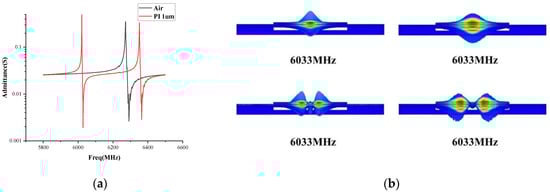
Figure 3.
(a) Absolute admittance curves for the conventional FBAR and polymer FBAR; (b) Resonance and antiresonance energy distribution.
3. Results and Discussions
3.1. Electrode
The simulation model AlN is selected as the piezoelectric layer with the thickness of 1 μm, and the thickness of the electrode is set to 0.1 μm. The polymer layer is a polyimide material with a thickness of 1 μm. Due to the low mechanical strength of the polymer layer, it can only provide the effect of bulk acoustic wave coupling. Hence, it is necessary to support the electrode-piezo-electrode sandwich structure. The Si3N4 materials with a higher mechanical strength is used as the support layer with the thickness of 1 μm. The top electrode is rectangular and the irregular pentagonal electrode suppresses the coupling of the parasitic modes and weakens the high-order resonances [42]. A model was established in COMSOL® Multiphysics 5.6 to simulate the effect of the electrodes of different materials on the intensity of the high-order resonance peak.
Figure 4a, shows the absolute value of the admittance for the electrode materials at different resonance frequencies. With the increase of the acoustic impedance, the magnitude of the first and the second resonance admittance decreases accordingly. Figure 4b shows the relationship between the admittance amplitude and the acoustic impedance of the electrodes. The metal electrodes with a higher density of Au, Ag, and Pt have a lower resonance strength, since they have a higher acoustic impedance which leads to a higher bulk acoustic wave reflection at the interface between the electrode and piezoelectric film. The electrode material with the lowest density is Al. Hence, it has the highest admittance at the resonance frequencies. Figure 4c shows that the second-order mode reflection coefficient of Al is the largest, and the Q factor is calculated by S11. The Q factor is Al 2121, Ti 1398, Mo 2021.
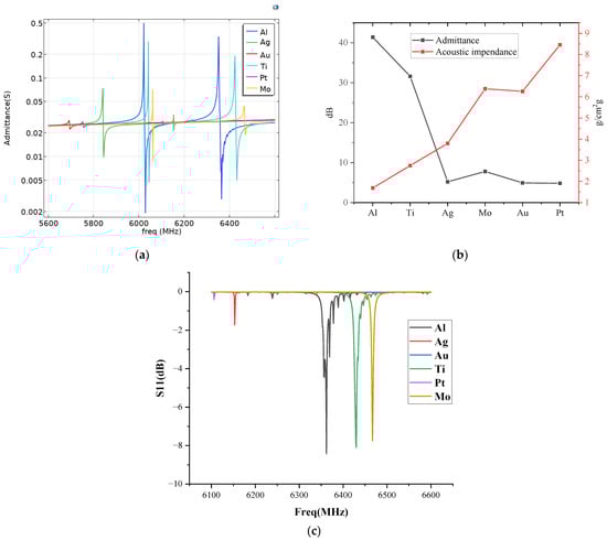
Figure 4.
(a) Absolute value of the admittance for the electrode materials; (b) Relationship between the admittance amplitude and the acoustic impedance of the electrodes; (c) S11 reflection spectra of the electrode materials.
3.2. Polymer Materials
There are many kinds of polymer materials, and Poisson’s ratio of Young’s modulus varies greatly among the different polymer materials. The acoustic vibration coupled by the piezoelectric film is transmitted to the polymer layer, and within the elastic limit, the high-order vibration mode of the piezoelectric layer can be strengthened or weakened. Four different polymer materials are selected for the simulation, namely: polyimide (PI), polyethylene (PE), polymethyl methacrylate (PMMA) and polyamide (PA). The mechanical parameters are provided by COMSOL® Multiphysics 5.6, as shown in Table 1.

Table 1.
Young’s modulus and Poisson’s ratio of common polymer materials.
Figure 5a shows the absolute value of the polymer materials’ admittance response at the different frequencies. As can be seen, the FBAR with the polyimide reflective layer has a higher resonance frequency. Since the PI has high thermal stability, a high insulation, and a high mechanical strength, it is an ideal polymer material for the polymer reflective layer FBAR. Figure 5b shows the S11 reflection spectra of the second-order resonance mode of the polymer FBAR. It can be seen that the PI FBAR has the highest resonance frequency. Its resonance frequency can reach 6.360 GHz. A variety of resonances coupled out because the polymer does not have a strict crystal structure, which helps the polymer FBAR to induce the higher frequency resonance.
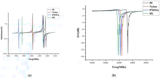
Figure 5.
(a) Absolute value of the polymer materials’ admittance response; (b) S11 reflection spectra of the polymer FBAR.
3.3. Polyimide Thickness
Figure 6 shows the absolute admittance of the polymer FBAR under different polyimide thicknesses. It can be seen that the resonance intensity and frequency of the second resonance peak of the PI FBAR under a thickness of 1μm, are higher than those of the other polymer thicknesses. The polyimide with a thickness between 1.0–1.4 μm, can couple out the second high-order resonance. When the thickness of the polymer layer increases to 2 μm, the second-order high-order strong resonance disappears. Moreover, for the polyimide films with a thickness of less than 1 μm, there is no second high-order resonance in the admittance spectrum. In an ideal fluid, there is no shear deformation and the coefficient of the viscosity is zero, so the medium has only a volumetric deformation in which only the compressional waves propagate. However, in the solid medium, in addition to the volume deformation, the shear deformation will be generated. Therefore, the deformation of the solid medium will generate two kinds of waves, namely, the compression wave and the shear wave. Therefore, when the bulk acoustic wave is incident into the polyimide film, multiple modes of acoustic waves are coupled, resulting in modes higher than the fundamental frequency.
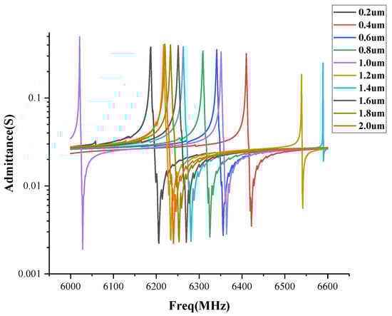
Figure 6.
Absolute admittance of the polymer FBAR against the different polyimide thicknesses.
3.4. Support Layer Thickness
The absolute admittance spectra under the different thicknesses of the Si3N4 support layer are shown in Figure 7. The admittance response amplitude and the frequency are higher as the thickness of the Si3N4 layer is between 0.7 μm and 1.4 μm, and the speed of the bulk acoustic wave is Si3N4 is 9000 m/s, and the wavelength of the acoustic wave under the frequency of 6.360 GHz propagating in the support layer is 1.4 μm, which is thinner than the half wavelength and maty induce, the acoustic wave coupling of the surface waves and shear waves. It should be noted that if the supported layer is thicker than the full wavelength, the longitudinal waves coupled out of surface waves and shear waves may be induced to cause a large loss of acoustic energy.
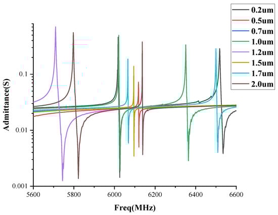
Figure 7.
Absolute admittance spectra against the different thicknesses of the Si3N4 support layer.
4. Discussion
In micro electric mechanical systems (MEMS), the selection of electrodes often has a great impact on the performance of the device. For example, Au and Pt have a high stability, therefore, it is mostly used in the more extreme external environments [43]. The melting point of Ir is 2450 °C, so Ir electrodes are often used in high-temperature devices [44]. However, for the polymer-FBAR, it is not only necessary to return the acoustic energy to the piezoelectric layer in order to form resonance, but it also requires the mechanical vibration coupling of the acoustic waves in the polymer layer, so the Al and Ti electrode materials with a low acoustic impedance are conducive to the leakage of acoustic waves into the polymer layer, forming complex multi-order coupling modes, and enhancing the high-order polymer FBAR resonance.
The FBAR is a high-frequency device. Under a high-frequency operation, heat will be generated due to the inherent loss of the material. Therefore, the high-temperature resistance of the polymer material will seriously affect the temperature stability of the FBAR. The PI is a better polymer material for high-temperature chips because of its high-temperature stability. The PI has good dielectric properties, and its dielectric constant is about 3.4, and can be reduced to about 2.5 by introducing fluorine or dispersing air nanometer size in polyimide. Its dielectric loss is 10−3, its dielectric strength is 100–300 kV/mm, and its volume resistance is 1017 Ω·cm. It should be noted that the polymer film used in this simulation is polyimide film and it has stable thermal characteristics. Hence, the proposed FBAR has a stable frequency response to temperature. A good crystal structure can be grown under extreme growth conditions without damaging the polyimide substrate [45].
Based on Stokes’ law, the amplitude attenuation of the elastic waves in a homogeneous medium and the x-direction [46]:
where A0 is the incident sine wave amplitude, α is the attenuation coefficient, which is greatly affected by the ω and temperature, as the temperature increases and the incident sine wave ω increases, the prompt attenuation coefficient sharply increases. The thin polyimide film is easy to leak the acoustic wave into the substrate, which induces the larger loss of the bulk acoustic wave, and the thicker polyimide film can suppress the generation of high-order resonance. Hence, the optimized polymer film thickness is needed.
The Si3N4 film has a relatively regular crystal structure so the loss of the acoustic wave energy is small. The analysis of the effect of Si3N4 thickness on the mode coupling in the FBAR of this study follows the resonator mode coupling and the characteristic dispersion of the SMR structure [10].The Si3N4 film with a thickness of less than 0.5 μm reduces the mechanical q value of the FBAR, which is not conducive to the mechanical stability of the FBAR; The high-order resonance reinforced by the film layer needs to be reflected back to the piezoelectric layer, to form resonance. In addition, the Si3N4 film larger than 1.5 μm will scatter this part of the sound wave, thus weakening the secondary resonance strength.
5. Conclusions
In summary, a novel polymer FBAR design is proposed. The effect of the polymer material, the electrode material, the thickness of the polymer layer, and the thickness of the support layer are optimized by using the finite element simulation method. It is found that the acoustic impedance of the heavy electrode material weakens the second resonance strength; the resonator with 1 μm PI polymer layer has a higher second resonance frequency; the Si3N4 support layer with a 1 μm thickness has a higher second resonance strength and a higher frequency. The research in this paper guides the design of the polymer FBAR with the polymer air cavity. In addition, the polymer air cavity acoustic wave resonators have a great potential in the direction of flexible wearable FBAR sensors.
Author Contributions
Conceptualization, B.D. and Y.H.; methodology, Y.H., L.L. and B.D.; resources, B.D., Z.W. and S.R.; data curation, Y.H. and B.D.; writing—original draft preparation, Y.H.; writing—review and editing, B.D., S.R. and Z.W.; supervision, B.D. All authors have read and agreed to the published version of the manuscript.
Funding
This research was funded by “Research Students University-Enterprise Cooperative Research Fund (20223108010010, Grant No. 20223108010010)”, “General project of Shenzhen university stability support plan (SZWD2021006)”, “Guangdong university innovation team project (Natural Science)(2020KCXTD029)”, “Special projects in key fields of colleges and universities of Guangdong Province (2021ZDZX1013)”, “Basic and Applied Basic Research Foundation of Guangdong Province Natural Science Foundation (2022A1515010841)”, “Shenzhen, Hong Kong and Macao Science and Technology plan (Class C) (SGDX20201103009520303)”, “Natural Science Foundation of Top Talent of SZTU (grant no. GDRC202103)”. “Special Fund for Scientific and Technological Innovation Strategy of Guangdong Province (Special Fund for “Climbing Plan”) (Pdjh2022b0463)” and “Guangdong Provincial Major Scientific Research Grant (Grant No. 2018KZDXM077)”; (* Corresponding author: Bo Dong).
Institutional Review Board Statement
Not applicable.
Informed Consent Statement
Not applicable.
Data Availability Statement
Not applicable.
Conflicts of Interest
The authors declare no conflict of interest.
References
- Skinner, J.L.; Cardinale, G.F.; Talin, A.A.; Brocato, R.W. Effect of critical dimension variation on SAW correlator energy. IEEE Trans. Ultrason. Ferroelectr. Freq. Control 2006, 53, 497–501. [Google Scholar] [CrossRef] [PubMed]
- Burkland, W.A.; Landin, A.R.; Kline, G.R.; Ketcham, R.S. A thin-film bulk-acoustic-wave resonator-controlled oscillator on silicon. IEEE Electron Device Lett. 1987, 8, 531–533. [Google Scholar] [CrossRef]
- Su, Q.X.; Kirby, P.; Komuro, E.; Imura, M.; Zhang, Q.; Whatmore, R. Thin-film bulk acoustic resonators and filters using ZnO and lead-zirconium-titanate thin films. IEEE Trans. Microw. Theory Tech. 2001, 49, 769–778. [Google Scholar] [CrossRef]
- Wang, J.; Park, M.; Mertin, S.; Pensala, T.; Ayazi, F.; Ansari, A. A Film Bulk Acoustic Resonator Based on Ferroelectric Aluminum Scandium Nitride Films. J. Microelectromech. Syst. 2020, 29, 741–747. [Google Scholar] [CrossRef]
- Chung, C.J.; Chen, Y.C.; Cheng, C.C.; Kao, K.S. Synthesis and bulk acoustic wave properties on the dual mode frequency shift of solidly mounted resonators. IEEE Trans. Ultrason. Ferroelectr. Freq. Control 2008, 55, 857–864. [Google Scholar] [CrossRef]
- Lv, L.; Shuai, Y.; Bai, X.; Huang, S.; Zhu, D.; Wang, Y.; Zhao, J.; Luo, W.; Wu, C.; Zhang, W. Wide Band BAW Filter Based on Single-Crystalline LiNbO₃; Thin Film With Insulating Bragg Reflector. IEEE Trans. Ultrason. Ferroelectr. Freq. Control 2022, 69, 1535–1541. [Google Scholar] [CrossRef]
- Gu, X.; Liu, J.; Cai, Y.; Liu, Y.; Gao, C.; Wen, Z.; Guo, S.; Sun, C. Laterally-excited bulk-wave resonators (XBARs) with embedded electrodes in 149.5° Z-cut LiNbO3. In Proceedings of the 2021 IEEE 16th International Conference on Nano/Micro Engineered and Molecular Systems (NEMS), Xiamen, China, 25–29 April 2021; pp. 931–934. [Google Scholar]
- Yandrapalli, S.; Eroglu, S.E.K.; Plessky, V.; Atakan, H.B.; Villanueva, L.G. Study of Thin Film LiNbO3 Laterally Excited Bulk Acoustic Resonators. J. Microelectromech. Syst. 2022, 31, 217–225. [Google Scholar] [CrossRef]
- Zaitsev, B.D.; Shikhabudinov, A.M.; Teplykh, A.A.; Kuznetsova, I.E. Liquid sensor based on a piezoelectric lateral electric field-excited resonator. Ultrasonics 2015, 63, 179–183. [Google Scholar] [CrossRef] [PubMed]
- Martin, F.; Jan, M.E.; Belgacem, B.; Dubois, M.A.; Muralt, P. Shear mode coupling and properties dispersion in 8GHz range AlN thin film bulk acoustic wave (BAW) resonator. Thin Solid Film. 2006, 514, 341–343. [Google Scholar] [CrossRef]
- Chubarov, M.; Mercier, F.; Lay, S.; Charlot, F.; Crisci, A.; Coindeau, S.; Encinas, T.; Ferro, G.; Reboud, R.; Boichot, R. Growth of aluminum nitride on flat and patterned Si (111) by high temperature halide CVD. Thin Solid Film. 2017, 623, 65–71. [Google Scholar] [CrossRef]
- Zhao, Z.; Qian, Z.; Wang, B.; Yang, J.S. Energy trapping of thickness-extensional modes in thin film bulk acoustic wave resonators. J. Mech. Sci. Technol. 2015, 29, 2767–2773. [Google Scholar] [CrossRef]
- Zhao, Z.; Qian, Z.; Wang, B. Energy trapping of thickness-extensional modes in thin film bulk acoustic wave filters. AIP Adv. 2016, 6, 015002. [Google Scholar] [CrossRef]
- Piazza, G. Piezoelectric Aluminum Nitride Vibrating Contour-Mode MEMS Resonators. J. Microelectromech. Syst. 2013, 15, 1406–1418. [Google Scholar] [CrossRef]
- Jamneala, T.; Bradley, P.; Shirakawa, A.; Thalhammer, R.K.; Ruby, R. An Investigation of Lateral Modes in FBAR Resonators. IEEE Trans. Ultrason. Ferroelectr. Freq. Control 2016, 63, 778–789. [Google Scholar] [CrossRef] [PubMed]
- Pang, H.-F.; Tao, R.; Luo, J.; Zhou, X.; Zhou, J.; McHale, G.; Reboud, J.; Torun, H.; Gibson, D.; Tao, K.; et al. Rayleigh and shear-horizontal surface acoustic waves simultaneously generated in inclined ZnO films for acoustofluidic lab-on-a-chip. Surf. Coat. Technol. 2022, 442, 128336. [Google Scholar] [CrossRef]
- Chen, D.; Wang, J.; Li, D.; Xu, Y.; Li, Z. Solidly mounted resonators operated in thickness shear mode based on c-axis oriented AlN films. Sens. Actuators A Phys. 2011, 165, 379–384. [Google Scholar] [CrossRef]
- Su, Z.; Ye, L.; Lu, Y. Guided Lamb waves for identification of damage in composite structures: A review. J. Sound Vib. 2006, 295, 753–780. [Google Scholar] [CrossRef]
- Bjurstrom, J.; Wingqvist, G.; Katardjiev, I. Synthesis of textured thin piezoelectric AlN films with a nonzero C-axis mean tilt for the fabrication of shear mode resonators. IEEE Trans. Ultrason. Ferroelectr. Freq. Control 2006, 53, 2095–2100. [Google Scholar] [CrossRef]
- Lakin, K.M. A review of thin-film resonator technology. IEEE Microw. Mag. 2003, 4, 61–67. [Google Scholar] [CrossRef]
- Koskela, J.; Plessky, V. Coupling-of-Mode Analysis of SAW Devices. Int. J. High Speed Electron. Syst. 2000, 10, 867–947. [Google Scholar]
- Wright, P.V. Low-cost high-performance resonator and coupled-resonator design: NSPUDT and other innovative structures. In Proceedings of the 43rd Annual Symposium on Frequency Control, Denver, CO, USA, 31 May 1989–2 June 1989; pp. 574–587. [Google Scholar]
- Wang, J.S.; Lakin, K.M. Sputtered C-Axis Inclined ZnO Films for Shear Wave Resonators. In Proceedings of the 1982 Ultrasonics Symposium, San Diego, CA, USA, 27–29 October 1982; pp. 480–483. [Google Scholar]
- Li, M.; Seok, S.; Rolland, N.; Rolland, P.-A. Design, realization and test of a 2.1GHz ultra-low phase noise oscillator based on BAW resonator. AEU-Int. J. Electron. Commun. 2011, 65, 602–607. [Google Scholar] [CrossRef]
- Chaudhary, S.; Singh, J.; Haque, F.Z. BVD and Mason’s modelling of piezoelectric bulk acoustic resonators for high frequency applications. Mater. Today Proc. 2022, 65, 2556–2559. [Google Scholar] [CrossRef]
- Tiersten, H.F. Linear Piezoelectric Plate Vibrations; Springer: New York, NY, USA, 1969. [Google Scholar]
- Zhang, R.; Jiao, X.Q.; Yang, J.; Zhong, H.; Shi, Y. Electrode influence on effective electromechanical coupling coefficient of thin film bulk acoustic resonators. Mater. Res. Innov. 2014, 18, S4-606–S4-609. [Google Scholar] [CrossRef]
- Li, N.; Qian, Z.; Yang, J. Two-dimensional equations for piezoelectric thin-film acoustic wave resonators. Int. J. Solids Struct. 2017, 110–111, 170–177. [Google Scholar] [CrossRef]
- Liu, Z.; Wu, H.; Ren, W.; Ye, Z.-G. Piezoelectric and ferroelectric materials: Fundamentals, recent progress, and applications. In Reference Module in Chemistry, Molecular Sciences and Chemical Engineering; Elsevier: Amsterdam, The Netherlands, 2022. [Google Scholar]
- Muralt, P. Piezoelectric Thin Films for MEMS. In Encyclopedia of Materials: Science and Technology; Buschow, K.H.J., Cahn, R.W., Flemings, M.C., Ilschner, B., Kramer, E.J., Mahajan, S., Veyssière, P., Eds.; Elsevier: Oxford, UK, 2001; pp. 6999–7008. [Google Scholar]
- Uchino, K. Fundamentals of Piezoelectrics. In Encyclopedia of Smart Materials; Olabi, A.-G., Ed.; Elsevier: Oxford, UK, 2022; pp. 1–21. [Google Scholar]
- Kuznetsova, I.; Nedospasov, I.; Smirnov, A.; Qian, Z.-H.; Wang, B.; Dai, X.-Y. Excitation and detection of evanescent acoustic waves in piezoelectric plates: Theoretical and 2D FEM modeling. Ultrasonics 2019, 99, 105961. [Google Scholar] [CrossRef] [PubMed]
- Nguyen, N.; Johannessen, A.; Rooth, S.; Hanke, U. The impact of area on BAW resonator performance and an approach to device miniaturization. Ultrasonics 2019, 94, 92–101. [Google Scholar] [CrossRef] [PubMed]
- Fan, L.; Zhang, S.-Y.; Zheng, K.; Lin, W.; Gao, H.-D. Calculation of electromechanical coupling coefficient of Lamb waves in multilayered plates. Ultrasonics 2006, 44, e849–e852. [Google Scholar] [CrossRef] [PubMed]
- Olsson, R.H.; Hattar, K.; Homeijer, S.J.; Wiwi, M.; Eichenfield, M.; Branch, D.W.; Baker, M.S.; Nguyen, J.; Clark, B.; Bauer, T.; et al. A high electromechanical coupling coefficient SH0 Lamb wave lithium niobate micromechanical resonator and a method for fabrication. Sens. Actuators A Phys. 2014, 209, 183–190. [Google Scholar] [CrossRef]
- Zhou, Q.-B.; Lu, Y.-K.; Zhang, S.-Y. Extraction of electromechanical coupling coefficient of piezoelectric thin films deposited on substrates. Ultrasonics 2001, 39, 377–382. [Google Scholar] [CrossRef]
- Muehleisen, R.T.; Swanson, D.C. Modal coupling in acoustic waveguides: Planar discontinuities. Appl. Acoust. 2002, 63, 1375–1392. [Google Scholar] [CrossRef]
- Chen, G.; Zhao, X.; Wang, X.; Jin, H.; Li, S.; Dong, S.; Flewitt, A.J.; Milne, W.I.; Luo, J.K. Film bulk acoustic resonators integrated on arbitrary substrates using a polymer support layer. Sci. Rep. 2015, 5, 9510. [Google Scholar] [CrossRef] [PubMed]
- Ylilammi, M.; Ella, J.; Partanen, M.; Kaitila, J. Thin film bulk acoustic wave filter. IEEE Trans. Ultrason. Ferroelectr. Freq. Control 2002, 49, 535–539. [Google Scholar] [CrossRef] [PubMed]
- Lin, R.-C.; Kao, K.-S.; Cheng, C.-C.; Chen, Y.-C. Deposition and structural properties of RF magnetron-sputtered ZnO thin films on Pt/Ti/SiNx/Si substrate for FBAR device. Thin Solid Film. 2008, 516, 5262–5265. [Google Scholar] [CrossRef]
- Nam, K.; Park, Y.; Ha, B.; Kim, C.; Shin, J.; Yun, S.; Pak, J.; Park, G.; Song, I. Monolithic 1-Chip FBAR duplexer for W-CDMA handsets. Sens. Actuators A Phys. 2008, 143, 162–168. [Google Scholar] [CrossRef]
- Makkonen, T.; Pensala, T.; Vartiainen, J.; Knuuttila, J.V.; Kaitila, J.; Salomaa, M.M. Estimating materials parameters in thin-film BAW resonators using measured dispersion curves. IEEE Trans. Ultrason. Ferroelectr. Freq. Control 2004, 51, 42–51. [Google Scholar] [CrossRef] [PubMed]
- Brachmann, E.; Seifert, M.; Ernst, D.; Menzel, S.B.; Gemming, T. Pt-wire bonding optimization for electroplated Pt films on γ-Al2O3 for high temperature and harsh environment applications. Sens. Actuators A Phys. 2018, 284, 129–134. [Google Scholar] [CrossRef]
- Clement, M.; Olivares, J.; Iborra, E.; González-Castilla, S.; Rimmer, N.; Rastogi, A. AlN films sputtered on iridium electrodes for bulk acoustic wave resonators. Thin Solid Film. 2009, 517, 4673–4678. [Google Scholar] [CrossRef]
- Petroni, S.; Tegola, C.L.; Caretto, G.; Campa, A.; Passaseo, A.; Vittorio, M.D.; Cingolani, R. Aluminum Nitride piezo-MEMS on polyimide flexible substrates. Microelectron. Eng. 2011, 88, 2372–2375. [Google Scholar] [CrossRef]
- Stokes, G.G. On the Theories of the Internal Friction of Fluids in Motion, and of the Equilibrium and Motion of Elastic Solids; GeoScienceWorld: McLean, VA, USA, 2007; Volume 24. [Google Scholar]
Publisher’s Note: MDPI stays neutral with regard to jurisdictional claims in published maps and institutional affiliations. |
© 2022 by the authors. Licensee MDPI, Basel, Switzerland. This article is an open access article distributed under the terms and conditions of the Creative Commons Attribution (CC BY) license (https://creativecommons.org/licenses/by/4.0/).