1. Introduction
Spaceborne Earth Observation (EO) data became available in the 1960s with the advances of artificial satellites. TIROS-1 [
1] was the first EO satellite launched in 1960, and it embarked two black and white television cameras. Then, the TIROS program continued with four generations of satellites launched until 1994.
The EO satellite industry has evolved to make more complex spacecrafts, including multiple experiments on-board, such as Envisat [
2] (2002), which is a European satellite that included eight different instruments, or the UARS [
3] (1991) from the United States, which had 10 instruments. However, today’s trend is toward constellations of more dedicated satellite missions, such as the Sentinels [
4], of the European Union Copernicus system.
In parallel, the so-called New Space industry has experienced rapid development of technologies for small satellites, especially since the appearance of the CubeSat standard [
5] in 1999. This standard defines satellites by Units (U), where each U corresponds to 10 × 10 × 10 cm and can weigh up to 2 kg, as defined in the standard.
Among the EO payloads for CubeSats or small satellites, those that make use of Global Navigation Satellite System Reflectometry (GNSS-R) are gaining momentum, as they are passive (i.e., power consumption is small), the spatial resolution does not depend on the antenna size, and they allow performing ocean monitoring [
6], obtaining soil moisture [
7], and detecting flooded regions [
8] or ice cover [
9]. This technique has been validated in missions such as the UK-DMC [
10], the UK TechnoDemoSat-1 (TDS-1) [
11], and the CYGNSS constellation from NASA [
12].
Additionally, combining GNSS-R with Microwave L-Band Radiometry (MWR) measurements improves the spatial resolution and accuracy of soil moisture and ocean salinity products [
13]. This was done in the FSSCat mission [
14] launched in 2020, in which the Flexible Microwave Payload 2 (FMPL-2) [
15] combined both a GNSS-R and an RAD.
The
Cat-4 mission [
16] is a successor from the FSSCat mission. This mission aims at demonstrating similar capabilities (dual-band L1 and L2 GNSS-R and MWR) in a 1 Unit (1U) CubeSat.
Cat-4 was selected by the ESA Fly your Satellite! 2 program, and it is planned to be launched in Q4 2022/Q1 2023 in the Ariane 6 maiden flight. The scientific payload is the Flexible Microwave Payload 1 (FMPL-1) [
17], and it is based on an RTL-SDR. Additionally, an uplooking Right Hand Circular Polarization (RHCP) antenna and a downlooking Left Hand Circular Polarization (LHCP) L-Band Helix Antenna (LHA) also conform the FMPL-1. This downlooking antenna is included in the Nadir Antenna and Deployment Subsystem (NADS).
This work aims at defining the requirements necessary for the LHA. A preliminary theoretical analysis is first conducted to identify the dimensions of the antenna to meet the requirements. This analysis is conducted taking into consideration the constrains for the whole range of frequencies, instead of designing for one particular frequency, which is common. Then, it is verified with simulations, and a sensitivity analysis of the size and shape of the ground plane (GP) is performed to optimize the performance given the restrictive dimensions of a 1U CubeSat. Additionally, the simulations and the model are verified with measurements of an Engineering Model (EM) with different sized GPs; these measurements provide added value to the overall study, since current state of the art is just based on simulations. Finally, the design and measurements of the Flight Model (FM) are presented.
This article is organized as follows:
Section 2 lists the LHA requirements.
Section 3 contains the theoretical analysis of the design.
Section 4 explains the results of the simulations performed, and it contains the GP sensitivity analysis.
Section 5 includes the measurements of the EM model with different GPs.
Section 6 presents the design and performance of the NADS FM. Finally,
Section 7 summarizes the conclusions.
2. L-Band Helix Antenna Requirements Definition
To fulfill the mission goals, the LHA has to be directive, have a high front-to-back lobe ratio (FBR), LHCP, occupy less than 0.3 U, and cover a wide range of frequencies in the L-Band, from 1227 MHz (GPS L2) up to 1575 MHz (GPS L1). The overall requirements with values for each of the operating frequencies can be found in
Table 1. These requirements have been defined by the Payload Engineer, and the scope of this work is to design an antenna compliant with them.
A common solution for GNSS-R payloads is to use an array of patch antennas that are placed on an external face of the satellite, as has been performned for TechDemoSat-1 [
11],
Cat-2 [
18], CyGNSS [
12], and FSSCat [
14]. Other solutions consider different types of materials for transmission line-type antennas [
19,
20], although these have a similar performance to regular patch antennas. An array of any patch or transmission line-based antenna with the required directivity would be composed of six elements, needing a 6 U face to allocate the antennas. So, although this solution is simple in terms of mechanical interfaces, it is not valid for the
Cat-4 mission, since it is a 1 U CubeSat.
Another solution is a helical antenna since it can be directive, broadband, and circularly polarized. These antennas are initially stowed in the satellite to then be deployed in orbit. Some missions have flown with commercial helical antennas, such as GOMX-1 [
21] and GOMX-3 [
22] as payload antennas, for ADS-B data acquisition. In addition, Lacuna Space [
23] launched an Internet of Things (IoT) payload with a helical antenna on-board a Nanoavionics spacecraft. Moreover, there is a commercial solution for a quadrifilar helical antenna [
24], but it occupies half a CubeSat Unit. Overall, helical antennas seem to be the best option for the
Cat-4 mission.
There are also some studies on deployable antennas; in [
25], a survey is performed on different types of antennas for CubeSats, and the equations and tools for the antenna design are provided. In addition, the design and testing on UHF [
26] and VHF [
27,
28] antennas has been the object of research. In [
29], there are also some large deployable antennas for CubeSats. Although there is literature on this topic, these solutions are not in the same frequency band and are not suitable for the
Cat-4 mission due to the stringent space restriction (0.3 U). Moreover, none of the current solutions assess the impact that the size and shape of the ground plane has on the antenna directivity [
30]. Thus, the LHA for
Cat-4 requires a custom design.
3. Theoretical Background
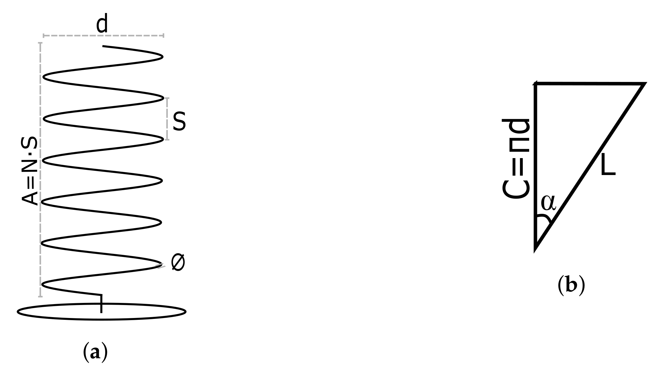
The first step in the design process is to perform a theoretical analysis. This way, approximate values of the dimensions of the LHA are obtained, which can be verified through simulations at a later stage. The analysis presents novelty in the methodology it uses, since it considers the most constraining case from the range of frequencies, instead of designing just for a single frequency. To ease the understanding of the theoretical analysis, it is necessary first to define the reference names for the geometry of a helical antenna.
This geometry and reference names are shown in
Figure 1, where
d is the diameter of the helix,
N is the number of turns,
S is the spacing between turns,
C is the circumference of the helix,
L is the length of one turn,
∅ is the section of the coil,
is the pitch angle,
A is the axial length of the deployed antenna, and
a is the axial length of the stowed antenna. Out of these, the most relevant parameters are
d,
N, and
S.
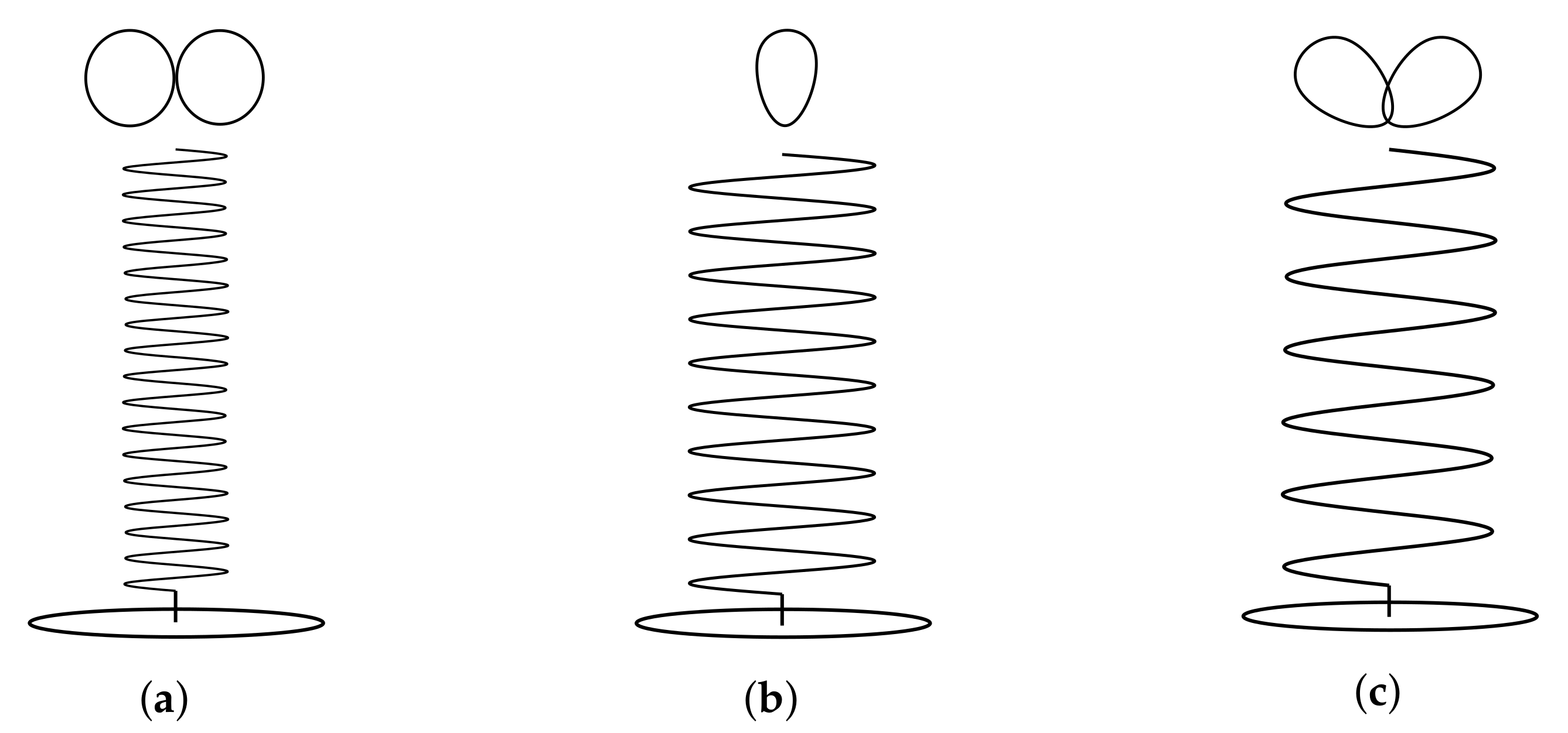
Helix antennas have three different radiation modes. This means that depending on the geometry of the antenna, the radiation pattern and directivity (D) change drastically. In
Figure 2, the radiation modes can be seen. The normal mode (
Figure 2a) radiates as a monopole, and it is achieved by significantly reducing S. In the case of the axial mode (
Figure 2b), it radiates in the axial direction and provides high directivities. To achieve it, both the d and S have to be increased with respect to the normal mode. Finally, the conical mode (
Figure 2c) has two lobes located at 45° with respect to the axial direction, and this mode is achieved by increasing significantly the diameter of the antenna.
Out of the three radiation modes, the most suitable one for the L-band Helix Antenna is the axial mode, since this mode ensures the maximum power density in the direction of its axis, and right or left hand circular polarization can be achieved depending on the direction of the antenna twisting. Thus, the LHA is designed following the axial mode geometry constraints.
The antenna radiates in the axial mode when the three conditions shown in Equation (
1) are fulfilled. In the case of the LHA, these requirements have to be fulfilled for the whole range of frequencies.
Taking into account the geometry of an unrolled antenna turn seen in
Figure 1b, it can be obtained through trigonometry that
. In addition, Equation (
1) must be fulfilled for the whole frequency range (
Table 2) by using the highest wavelength value for lower bounds and the lowest wavelength value for upper bounds, as seen in Equation (
2).
Finally, substituting the wavelength values in Equation (
2), the upper and lower bounds for each condition are obtained:
The dimensions of the antenna (
Table 3) have been chosen to be inside that range. First, by fixing the spacing between turns (S) to the middle of the range, the
d,
,
C, and
L values are obtained. Moreover, the twisting of the helix is assumed to be toward the left, obtaining LHCP.
Then, the parameters that are not determined by S are the N, A, a, and ∅. For N, it is fixed based on the D; thus, this value is augmented until the D requirements are achieved. A margin of safety of 20% has been considered since the theoretical approximation of D is optimistic with respect to reality. This value has been taken from previous experience, comparing theoretical directivities with simulation results.
The D is computed as shown in Equation (
4):
where the normalized radiation pattern is calculated as:
and the electric field as:
The results for the
D can be seen in
Table 4. As it can be seen, the
D with the margin of safety fulfills the requirements for the L-Band Helix Antenna, and these requirements correspond to
turns.
Having N fixed, the axial length can be computed as . Thus, the final parameter left to define is the section of the coil. It has been chosen to be 1 mm, since the antenna must be flexible, to be easily stowed.
4. Simulation Results
This section contains the simulation results performed with the antenna design defined in
Section 3. Along with the different simulations, the impact of the GP is assessed, and a solution that complies with the LHA requirements (D, FBR, and GP dimensions and shape) is presented.
4.1. Assumptions and Modeling
The antenna and the CubeSat structure have been modeled using SolidWorks and the electromagnetic behavior with CST Studio Suite using the Frequency Solver. To perform the simulations, certain assumptions have been made when modeling the antenna. These are listed below:
The antenna has the measurements specified in
Section 3.
The ground planes have a thickness of 35 m.
The ground plane’s material is copper.
The antenna’s material considered is Steel 1008.
The antenna is fed emulating a connector conformed on the outside by the ground plane, an FR-4 dielectric insulator, and the antenna wire as the inner connector.
The antenna is fed using a waveguide port.
Other subsystems in the satellite are not considered in the model.
4.2. Ground Plane Impact Analysis
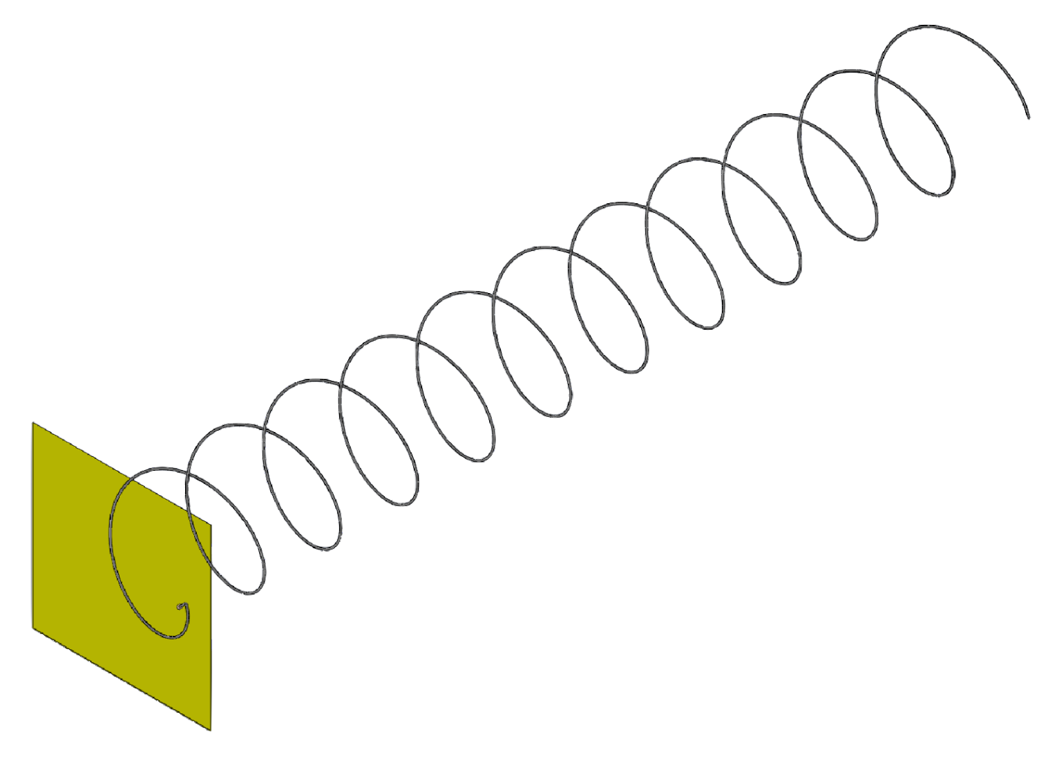
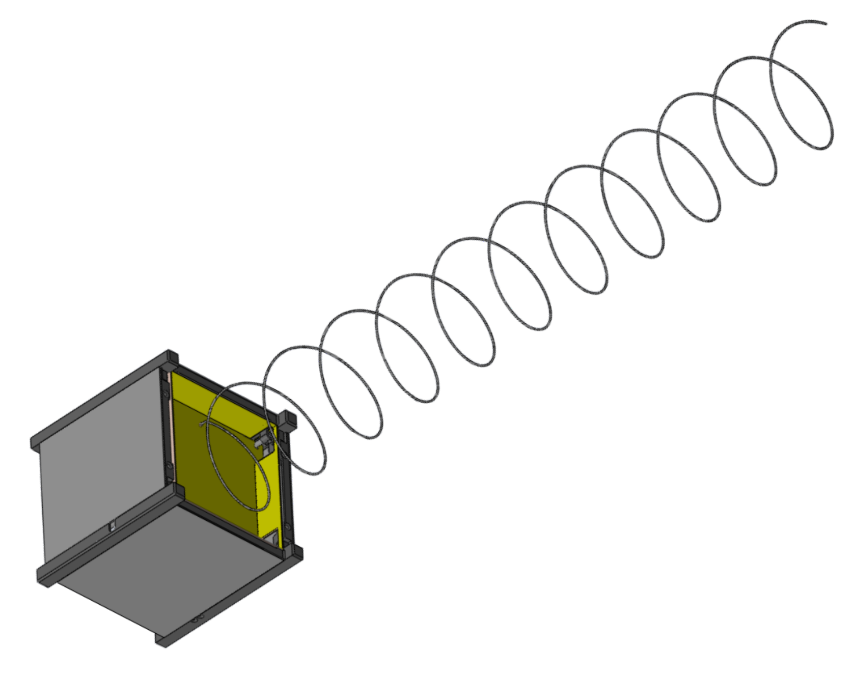
Initially, two different cases are studied. One considers an infinite GP, as seen in
Figure 3. According to [
31], a GP can be considered “infinite” if it is larger than
, although for the study, a GP of
by
(217.4 mm) has been simulated. This case is considered as the reference value for the other model, which is just 94 mm by 90 mm GP, (
Figure 4), which is the space available for the GP inside a 1 U CubeSat.
The simulation results are shown in
Table 5. First comparing the results from the infinite GP to the theoretical directivities obtained in
Table 4, it can be seen that the simulated values are lower than the theoretical ones. This was expected since theoretical calculations do not consider the different materials, the losses, or the size of the GP.
Moreover, comparing the simulated results between the infinite and CubeSat-sized GPs, it can be seen that the lower the frequency (i.e., the higher the wavelength), the larger the effect it has on the antenna performance both in terms of D and FBR. Taking a closer look at the D, it can be seen how at 1227.6 MHz, it is 2.01 dB less than the CubeSat-sized GP. For the MWR band, the D is the same, while for GPS L1, it has 0.2 dB more. In the case of the FBR, it is mostly affected by the reduction in the size of the GP. Thus, alternative GP solutions have been explored to assess if the FBR improves.
4.3. Ground Plane Shapes Analysis
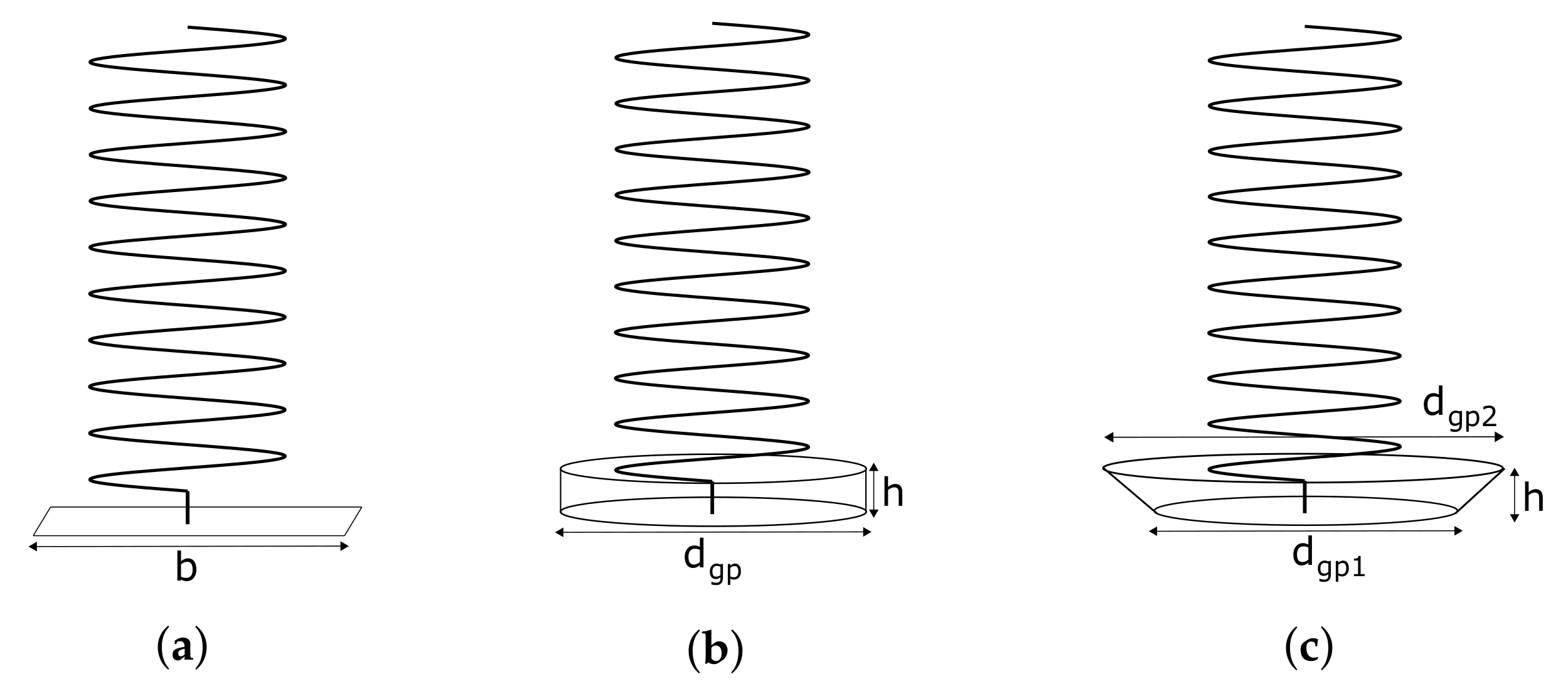
Following [
32], four alternative GPs are simulated: (1) an infinite GP, as used in the previous analysis; (2) a square GP (
Figure 5a); (3) a cylindrical GP (
Figure 5b); and (4) a conical GP (
Figure 5c). For each of these configurations, the optimum dimensions identified in the reference are used and are compared with the infinite GP.
“Infinite” ground plane: For this configuration, the same assumption as in the previous section has been taken of by . For the rest of this section, it will be referred to as .
Square ground plane: This plane is calculated considering two different measurements of the side (b), one with and the other with , which should give more D and less FBR.
Cylindrical cup ground plane: This plane should provide more D than the square GP. According to [
32], the optimum dimensions are
and
(
Figure 6d).
Conical ground plane: This GP should act as a reflector and provide the largest D of all other GPs. The optimum dimensions are
,
and
(
Figure 6c).
Figure 6.
Analysis ground plane models. (a) Square model with 0.5 GP. (b) Square model with 1.5 GP. (c) Model with conical GP. (d) Model with cylindrical GP.
Figure 6.
Analysis ground plane models. (a) Square model with 0.5 GP. (b) Square model with 1.5 GP. (c) Model with conical GP. (d) Model with cylindrical GP.
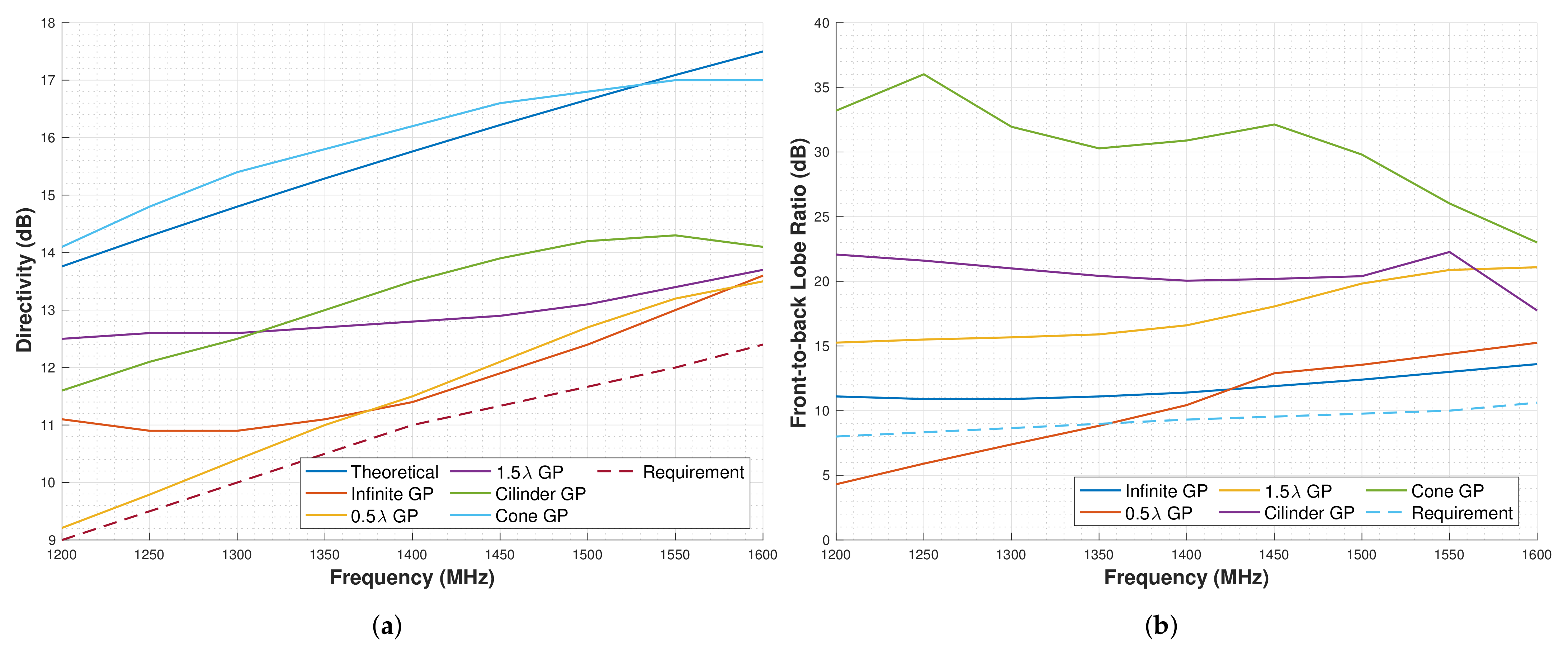
The results for these analyses are shown in
Figure 7a,b, where the first one represents a comparison of the D, and the second one represents the FBR.
Comparing the results for the D, several conclusions can be drawn. Regarding the GP, it can be seen that it does not maximize the D, since other smaller GPs can provide even higher Ds. Regarding the square GP, the D is lower for low frequencies and equal to the infinite GP for higher. For the 1.5 GP, the D is higher than for the GP. The cylinder has higher D for frequencies above 1300 MHz is even higher than for the 1.5 . Finally, the conical GP has even more D than the theoretical one.
Comparing the FBR, it can be seen that the GP does not provide enough FBR to meet the requirements. The other GPs do comply with the requirements; in the case of the , the results provide 15 dB of FBR for the whole range, and for the cylindrical, the results are even better having around 20 dB of FBR. The GP has between 35 and 25 dB of FBR, and for the conical GP, the FBR is the highest in almost the whole frequency band.
Overall, the GPs that comply with both D and FBR requirements are the square GP, the cylindrical, the conical, and the . However, all of these GP are not able to fit in a 1U CubeSat.
Out of all of these, the cylindrical GP is easier to integrate in a smaller dimension within the CubeSat structure. However, given that the structure of the CubeSat is squared-shaped, it would be ideal and even easier to integrate a cubic cup GP. For this reason, in the following subsection, a comparison between the cylindrical and the cubic cup GPs is made.
4.4. Cylindrical and Cubic Cup Ground Plane Comparison Analysis
As identified previously, the ideal dimensions for the Cylindrical cup GP are and . However, in the CubeSat, these dimensions do not fit, the maximum dimensions that can fit are = 96 mm ≈ 0.45 and h = 20 mm ≈ 0.1 . For this reason, the cylindrical cup GP is simulated for different and h sizes, and the D is studied.
For the analysis, first, the is altered between , leaving the optimum . Then, the h is altered between , leaving the optimum .
The results for these analyses are shown in
Figure 8a,b, being the first sweep in
and the second in
h. For the case of the
, it can be seen that as D reduces, the GP size is also reduced. For the specific case of
, the D is decreased by approximately 3 dB in all bands with respect to the maximum D. For
, the highest D is obtained, and for
, D decreases approximately 0.5 dB.
Overall, these simulations show that the CubeSat dimensions are actually restricting the antenna performance. However, the performance is better than for other GPs that can be fitted within the CubeSat.
The results presented in
Table 6 show that the Cubic Cup GP provides higher D in all bands and the FBR is lower in GPS L2 but higher for the rest of the bands. Although this Cubic Cup GP does not comply with the FBR requirement for the GPS L2 band (Table 8), this is the GP configuration selected for the final CubeSat design because of the better performance for the rest of the parameters.
4.5. CubeSat Structure Impact Analysis
This final analysis plans to assess the impact that the CubeSat structure itself has on the antenna performance. This is done by simulating the Cubic Cup GP standalone (
Figure 9), and with the CubeSat structure and solar panels, (
Figure 10).
The results for these simulations are shown in
Table 7. As it can be seen, the results both in D and FBR appear to be worse for the model with the CubeSat structure. However, it would be better to assess this in a prototype with real measurements, since the structure has a complex geometry, and this is not often well parametrized by the simulation software. Finally, a summary of the requirements compliance with all models simulated along this section can be found in
Table 8.
6. Flight Model Results
In this section, the design and performance of the LHA Flight Model (FM) are presented, detailing the final design, matching, and radiation pattern performance.
6.1. Design
The Flight Model of the LHA is included within the Nadir Antenna and Deployment Subsystem (NADS). The NADS not only includes the antenna but also contains the deployment mechanism. A detailed description of this deployment mechanism and the qualification tests done to verify its correct functionality is available in [
34]. Moreover, a characterization of the deployment and the effect it has on the satellite can be found in [
35].
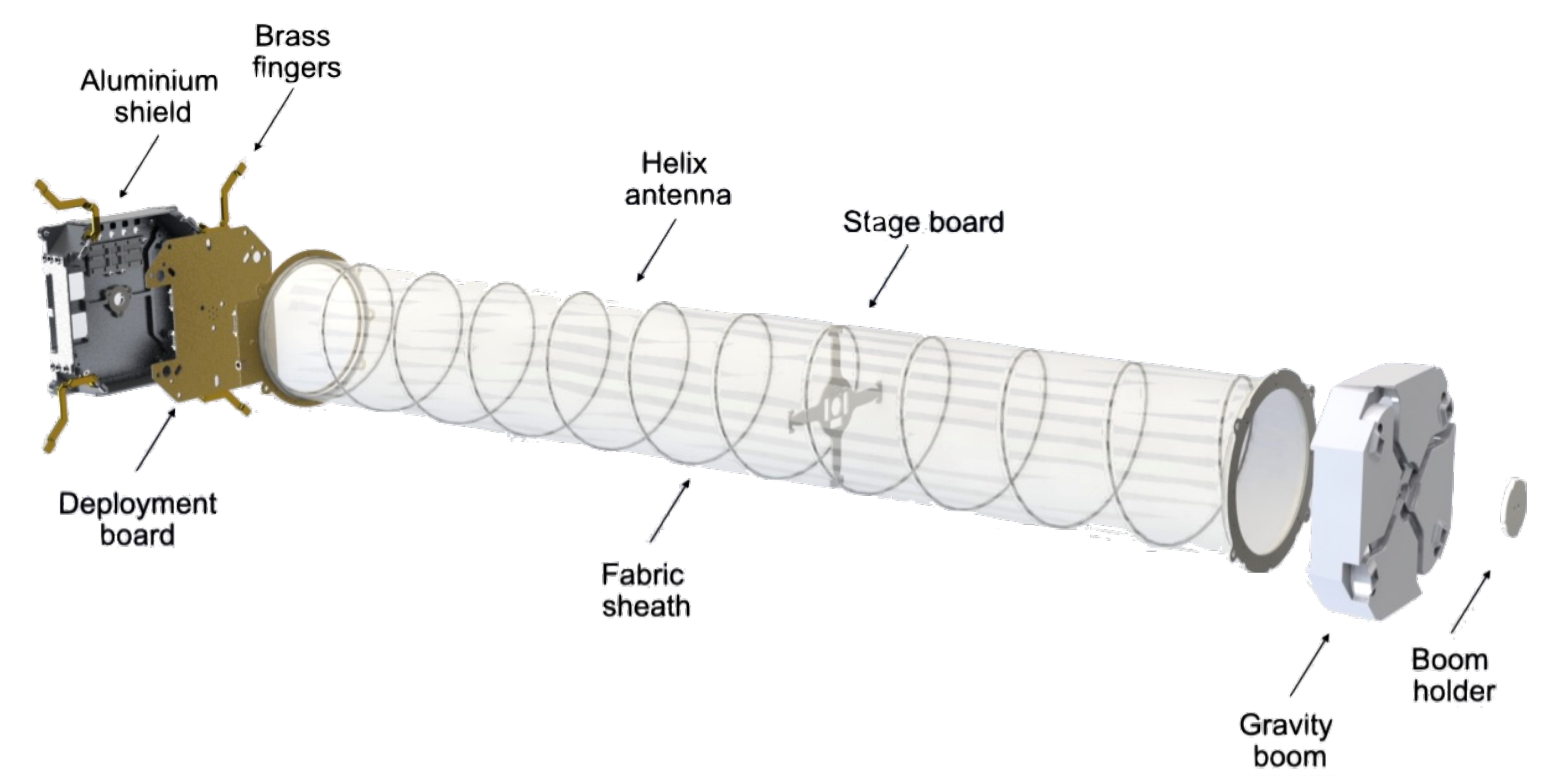
The design of the NADS is presented in
Figure 12. The different elements of the subsystem and their functionalities are explained below:
Aluminum shield: this part serves both as GP and as a mechanical support for the deployment mechanism.
Deployment board: this PCB contains the circuitry for the antenna deployment.
Brass fingers: these hold the antenna in stowed configuration.
Helix antenna: is the designed radiating element.
Fabric sheath: this fabric holds the shape of the antenna and provides rigidity.
Stage board: PCB used to hold the antenna halfway through the deployment.
Gravity boom: this part first helps to hold the antenna compressed by providing a surface where the fingers lock, and it also acts as a boom for the satellite’s attitude control. It also slightly increases the directivity because of its dielectric constant.
Boom holder: this piece holds the fingers locked to the gravity boom and prevents overall movement to the antenna when stowed.
The dimensions of the subsystem are 87 mm × 87 mm × 27.5 mm stowed, and 87 mm × 87 mm × 515 mm deployed. In the end, the GP had to be slightly reduced, since it was not possible to integrate the 94 by 98 mm GP.
The materials, manufacturing, and surface treatments used for the different parts of the NADS are listed in
Table 13. The most relevant ones for this particular case are the aluminum shield, which is made out of aluminum 7075 and has a surtec 650 treatment to ensure electrical conductivity. In addition, the antenna has been made out of spring steel, and a tin surface treatment has been applied so it can be soldered to the output connector.
6.2. Antenna Matching
The matching of helical antennas is traditionally done by inserting copper or other metallic pieces between the first turn of the antenna and the GP. This methodology changes the input resonance impedance of the antenna, and it can be matched to 50 by adding or removing the quantity of the material.
Although this methodology is easy, fast, and it can be done by trial and error, it is not suitable for the NADS, because it can be damaged when the antenna is stowed. Instead, the following methodology has been implemented.
The NADS matching methodology is inspired by [
36], where it is suggested to leave part of the last turn of the antenna parallel to the GP. In the NADS, it would be difficult to ensure this spacing between the antenna and the GP, especially after stowing and deploying the antenna. Therefore, an alternative solution had to be taken.
The final solution has been to place a 1 mm thick FR-4 PCB between the antenna and the GP to ensure this distance is always constant. The matching is tuned by sewing part of this last turn to the FR-4 PCB. This matching process was first performed in the Qualification Model (QM), where up to the first half of the antenna was sewed to the FR-4 PCB. Finally, the best results were obtained sewing a quarter of a turn.
These results measured in a Vector Network Analyzer (VNA) are presented in
Figure 13, showing around
dB of S11 in the GPS L2 band,
dB in the Radiometer band, and
dB in the GPS L1 band. This last value for GPS L1 has been considered as valid, even being higher than the
dB common value, which is the best matching value that could be obtained. Given that the range of frequencies in which the antenna has to operate is quite broad, the process was extremely challenging.
6.3. Radiation Pattern
The radiation pattern of the NADS FM was also measured in the UPC Antenna Lab Anechoic Chamber [
33]. A picture of this subsystem integrated in the chamber’s rotor is shown in
Figure 14.
Measured results are shown in
Table 14 and the radiation patterns in
Figure 15. These results are compliant with the requirements presented, and they are similar to the ones with the engineering model (
Table 12). Finally, in this measurement, the gain was also measured, and it shows that the antenna is correctly matched, as expected from the results shown in
Figure 13.
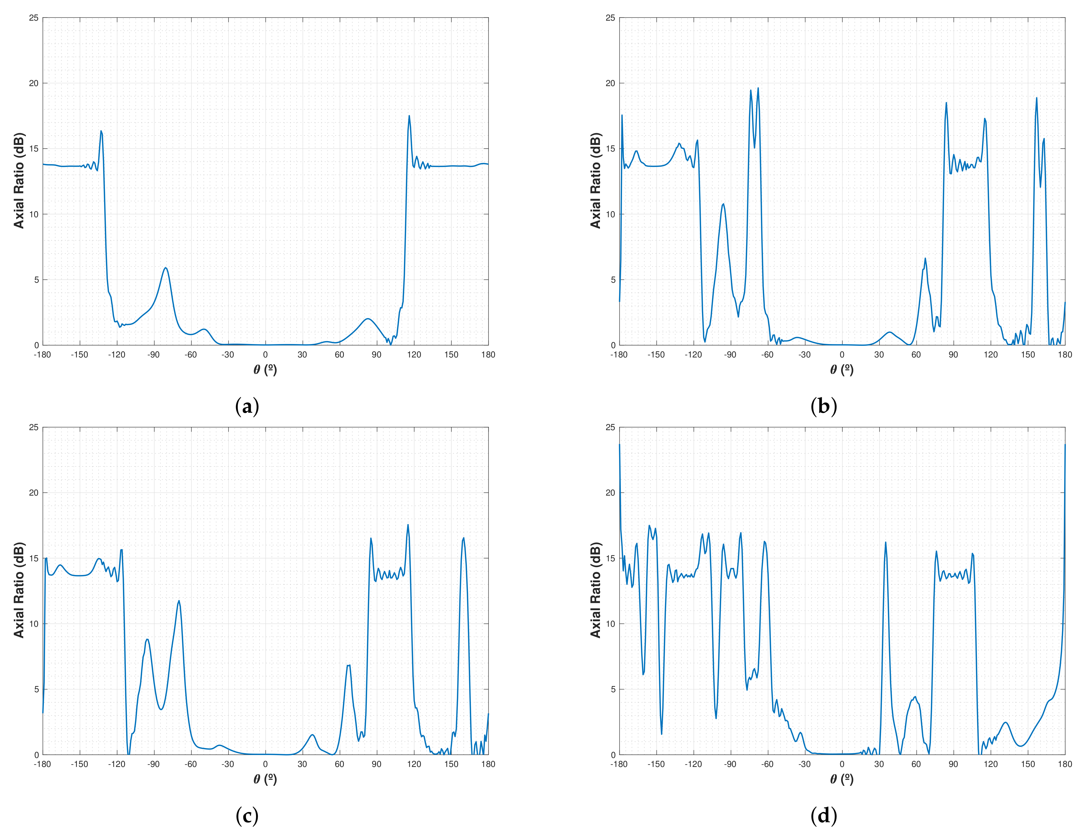
The axial ratio (AR) for LHCP was also measured in the NADS FM. The results (
Figure 16) show that the antenna has AR approximately 0 dB from −30° up to 30° in all frequencies. This complies with the LHCP requirements, since an antenna is considered circularily polarized as long as the axial ratio is lower than 3 dB.
7. Conclusions
This study has presented the design, electromagnetic simulation, prototyping, and FM results of the LHA downlooking antenna of the FMPL-1 GNSS-R and MWR payload. This antenna will fly on-board the NADS Subsystem of the Cat-4 mission which will be launched in the Ariane 6 maiden flight.
The first step of the study was the theoretical antenna design; from this, the dimensions of the antenna have been obtained. With these dimensions, a sensitivity analysis for different GP shapes and dimensions has been conducted. Among the different GPs analyzed, the “infinite” GP has been taken as the reference, at the end, the GP that provides more performance and can fit inside a CubeSat structure is a cubic cup GP. This GP provides dB of D and dB of FBR for the GPS L2 band, above dB of D and dB of FBR in the mwRAD band, and dB of D and dB of FBR for GPS L1.
Following the simulations, a prototype of the antenna has been manufactured and measured with different shapes of GP. The final shape, also given by the good performance in the simulations, has been the same cubic cup GP identified in the simulations. The results of this GP measured with the CubeSat structure were dB of D and dB of FBR for the GPS L2 band, above dB of D and dB of FBR in the mwRAD band, and dB of D and dB of FBR for GPS L1.
Finally, the FM has also been presented, with the final design, matching, and radiation pattern, satisfying all the requirements. The values obtained from the FM were dB of D and dB of FBR for the GPS L2 band, above dB of D and dB of FBR in the mwRAD band, and dB of D and dB of FBR for GPS L1.


 ,
, 


