
Quad-Port Multiservice Diversity Antenna for Automotive Applications

 , ,
, ,  ,
,
Abstract
:1. Introduction
2. Antenna Design
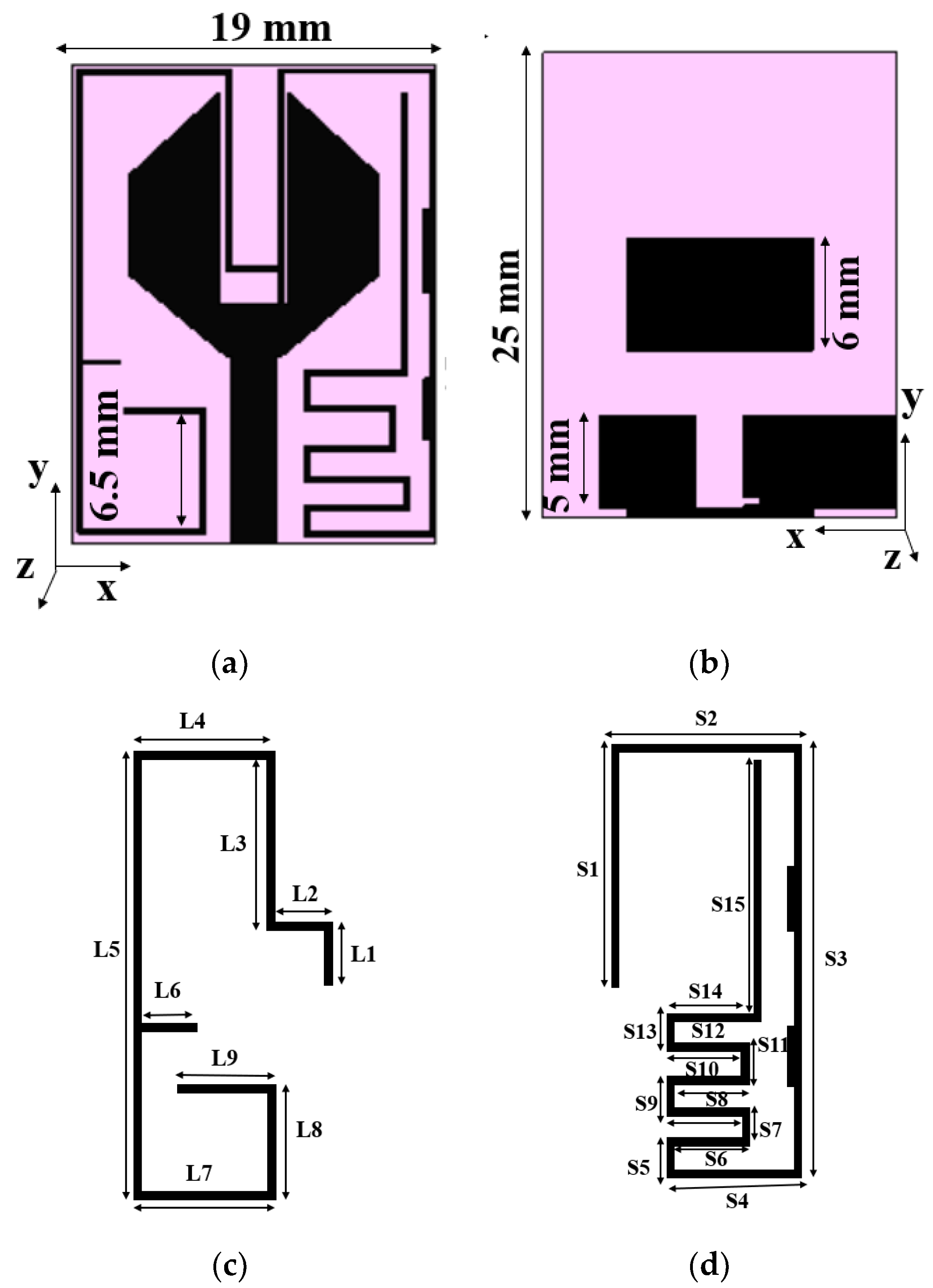
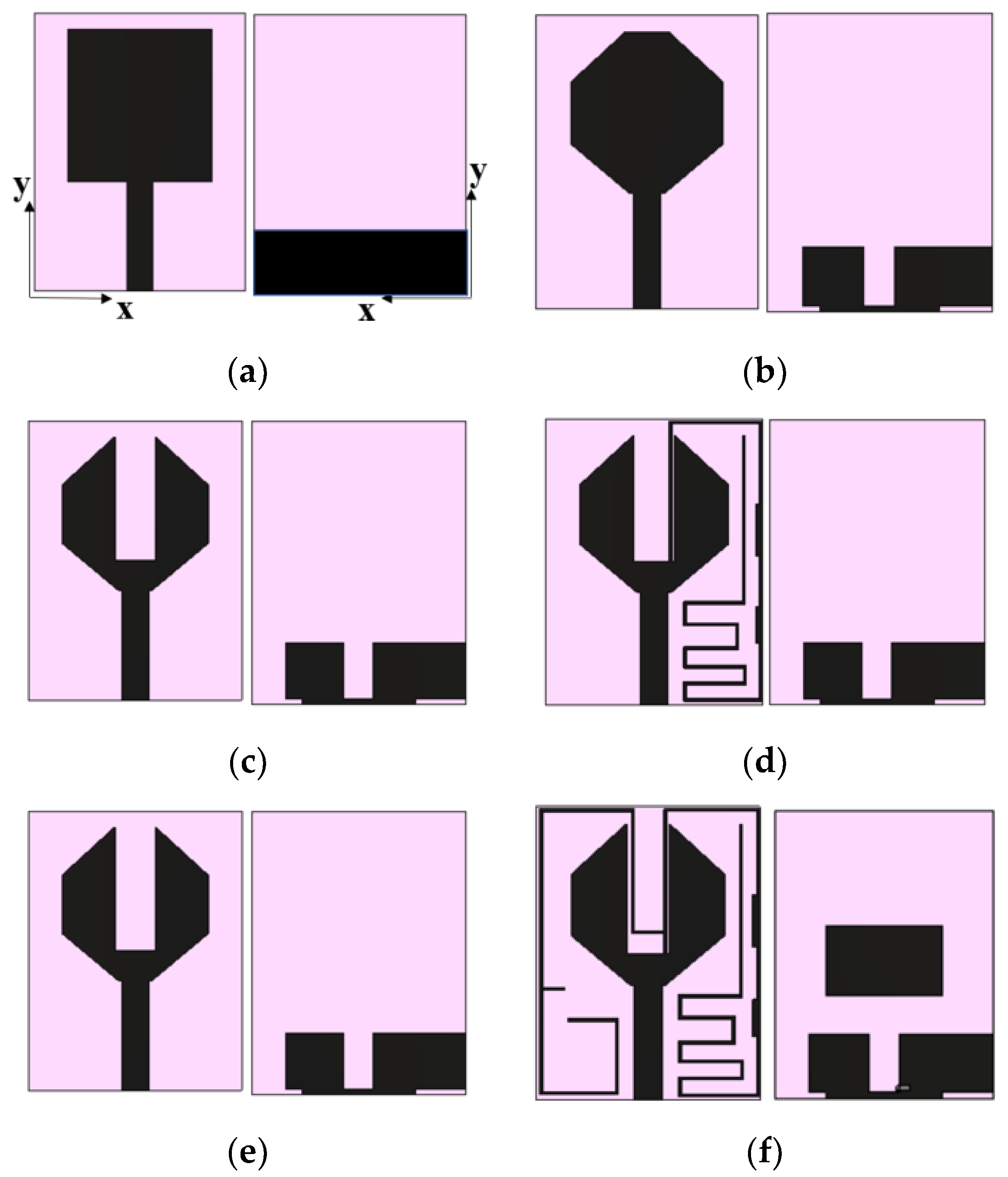
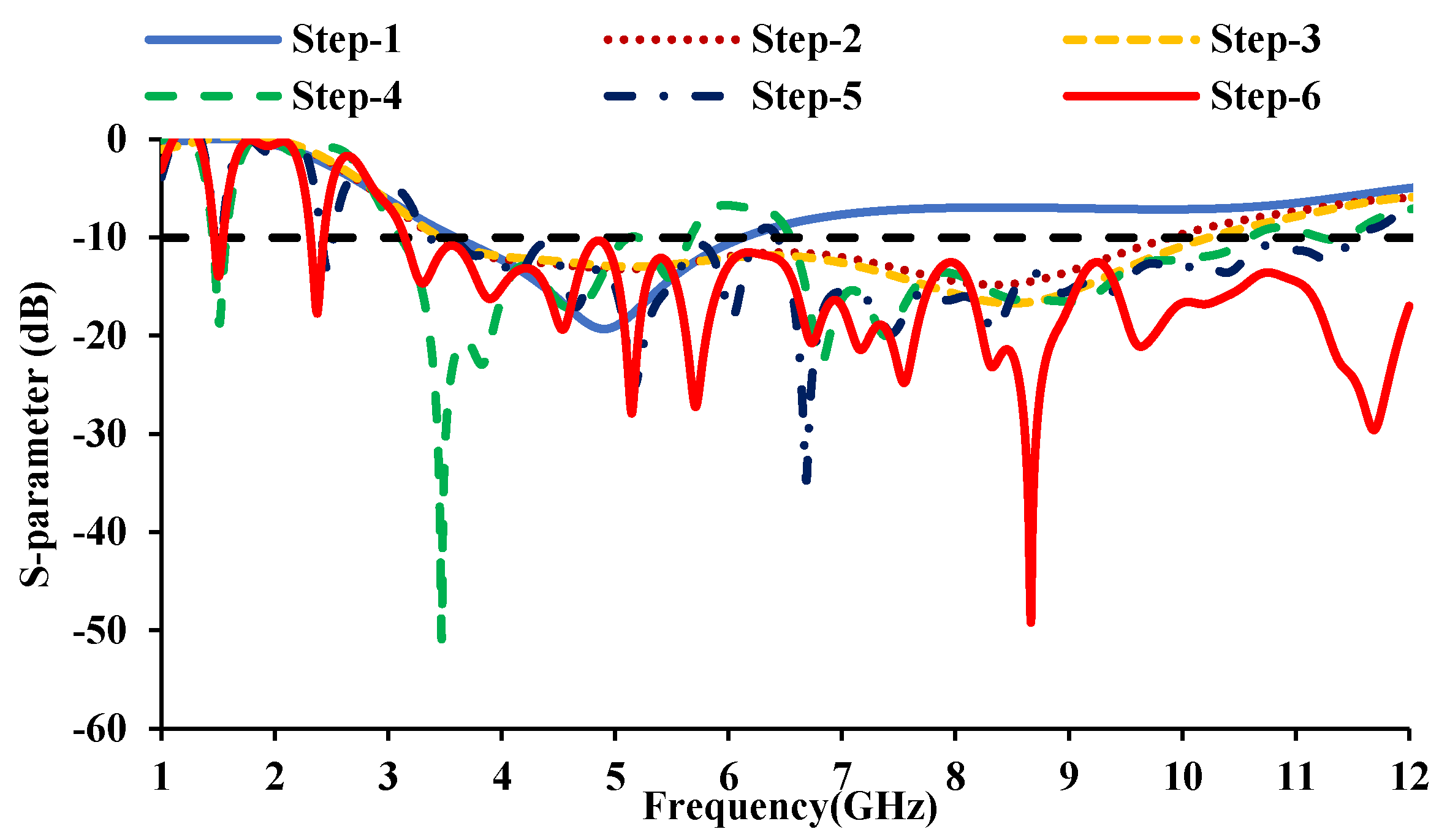
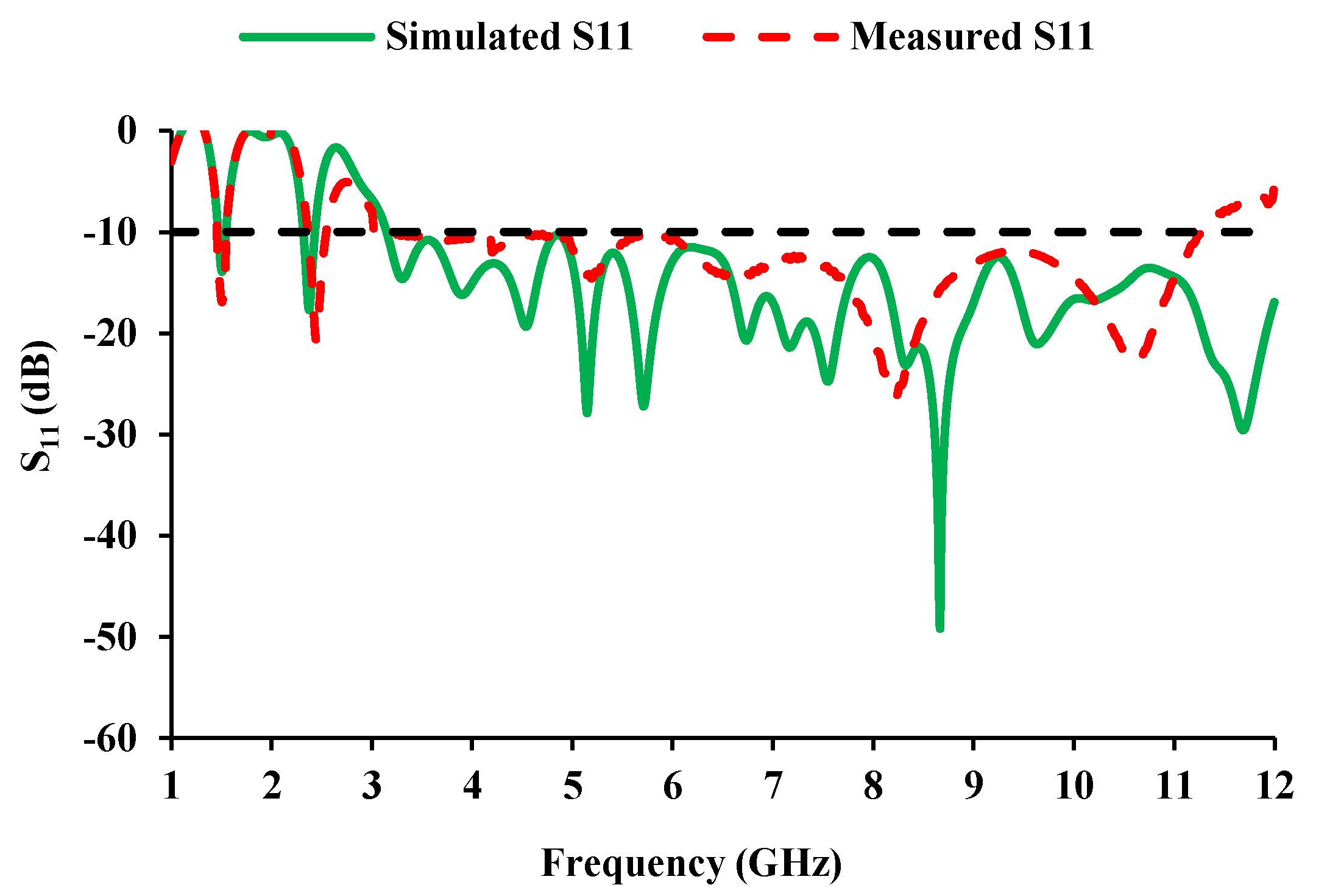
2.1. Antenna Element
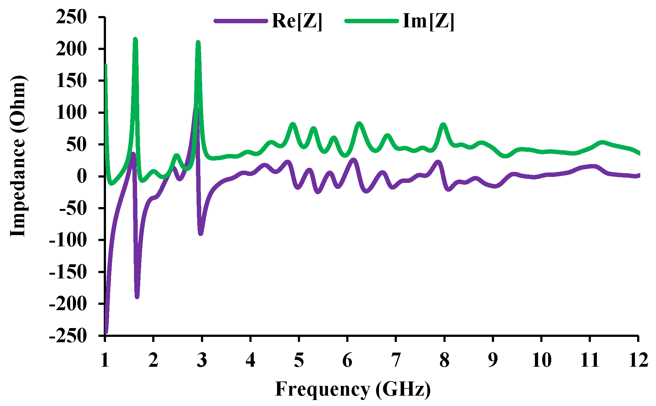
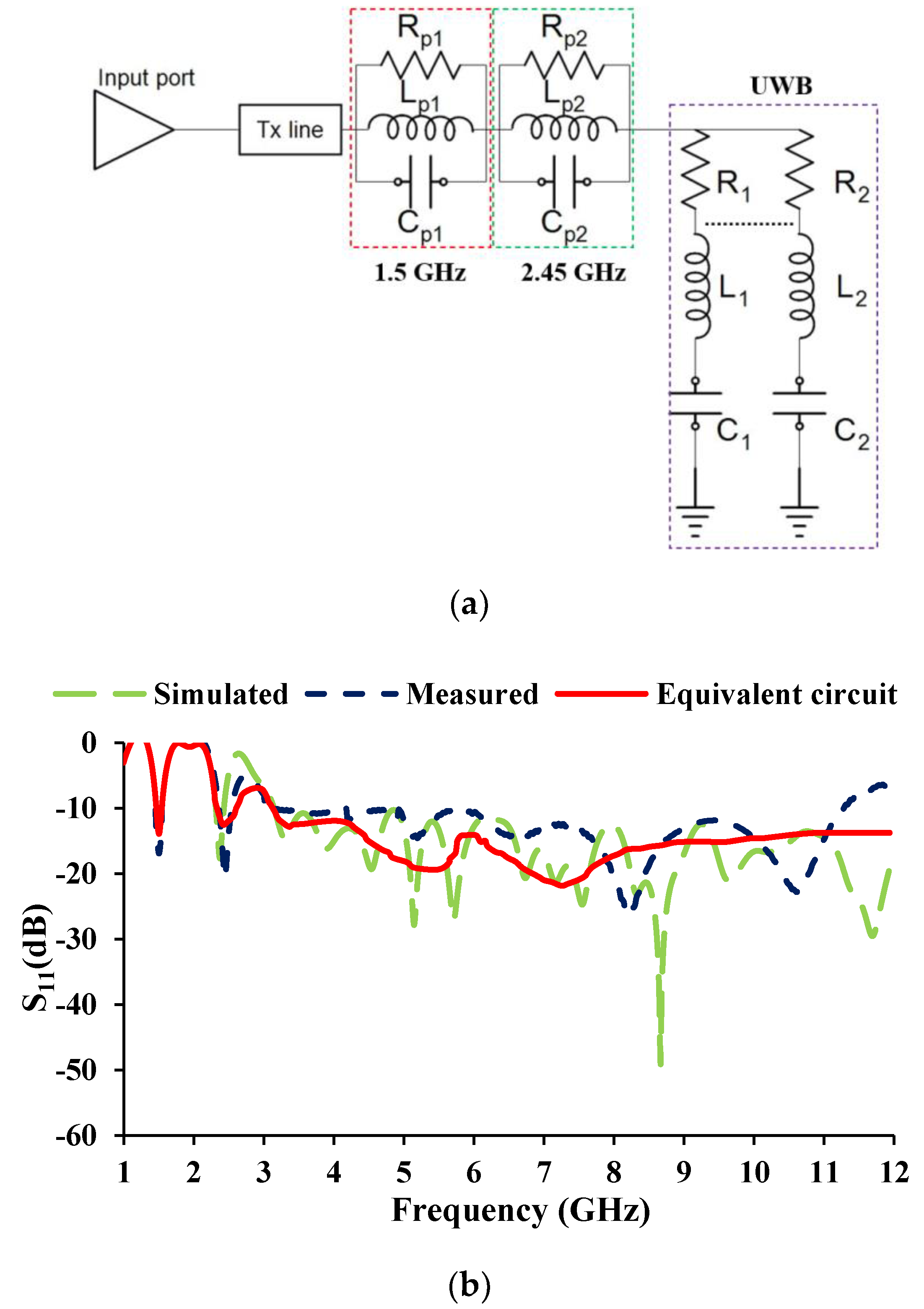
2.2. Equivalent Circuit
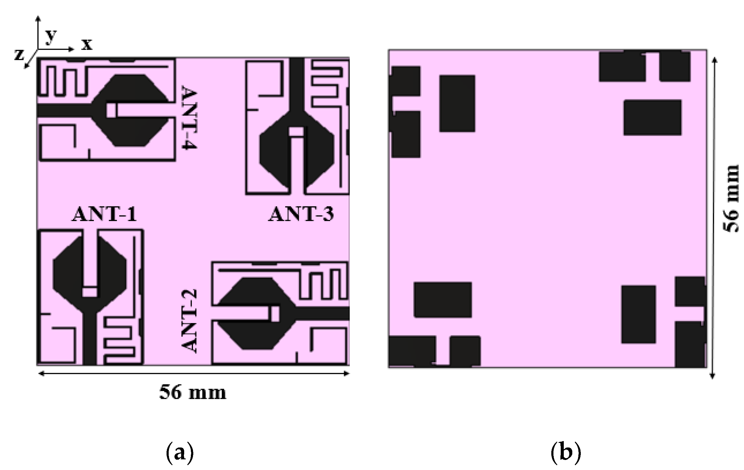
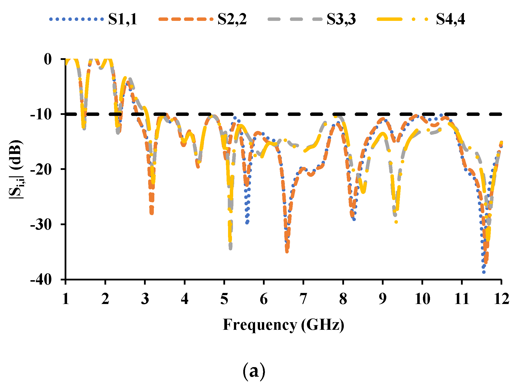
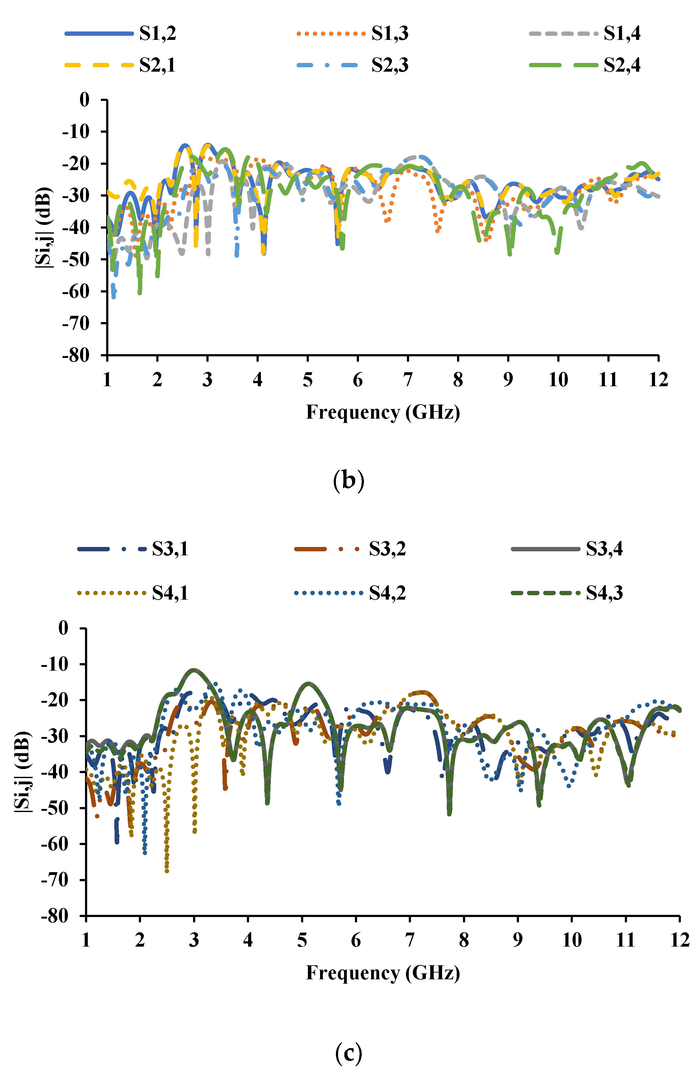
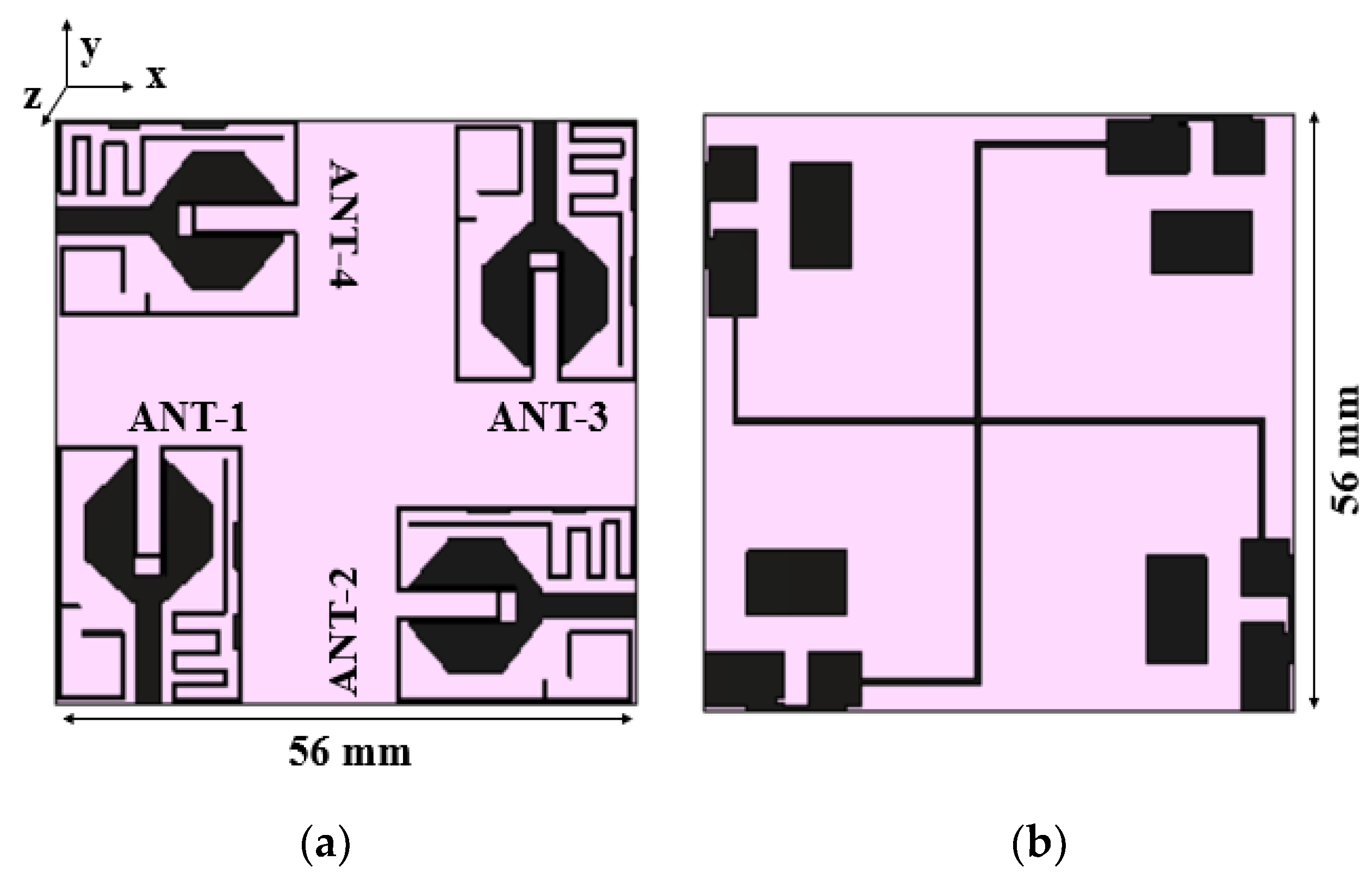
2.3. MIMO Antenna
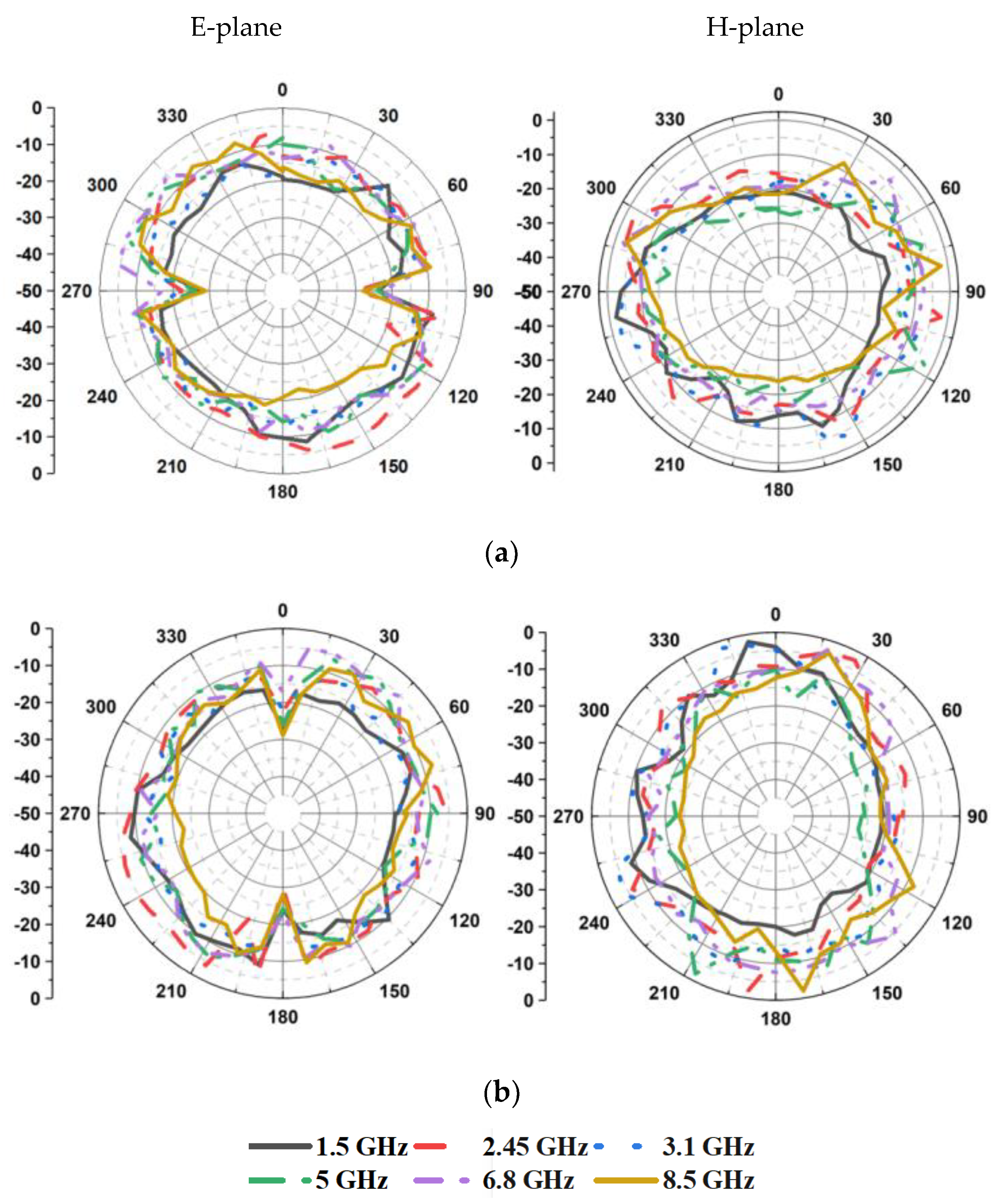
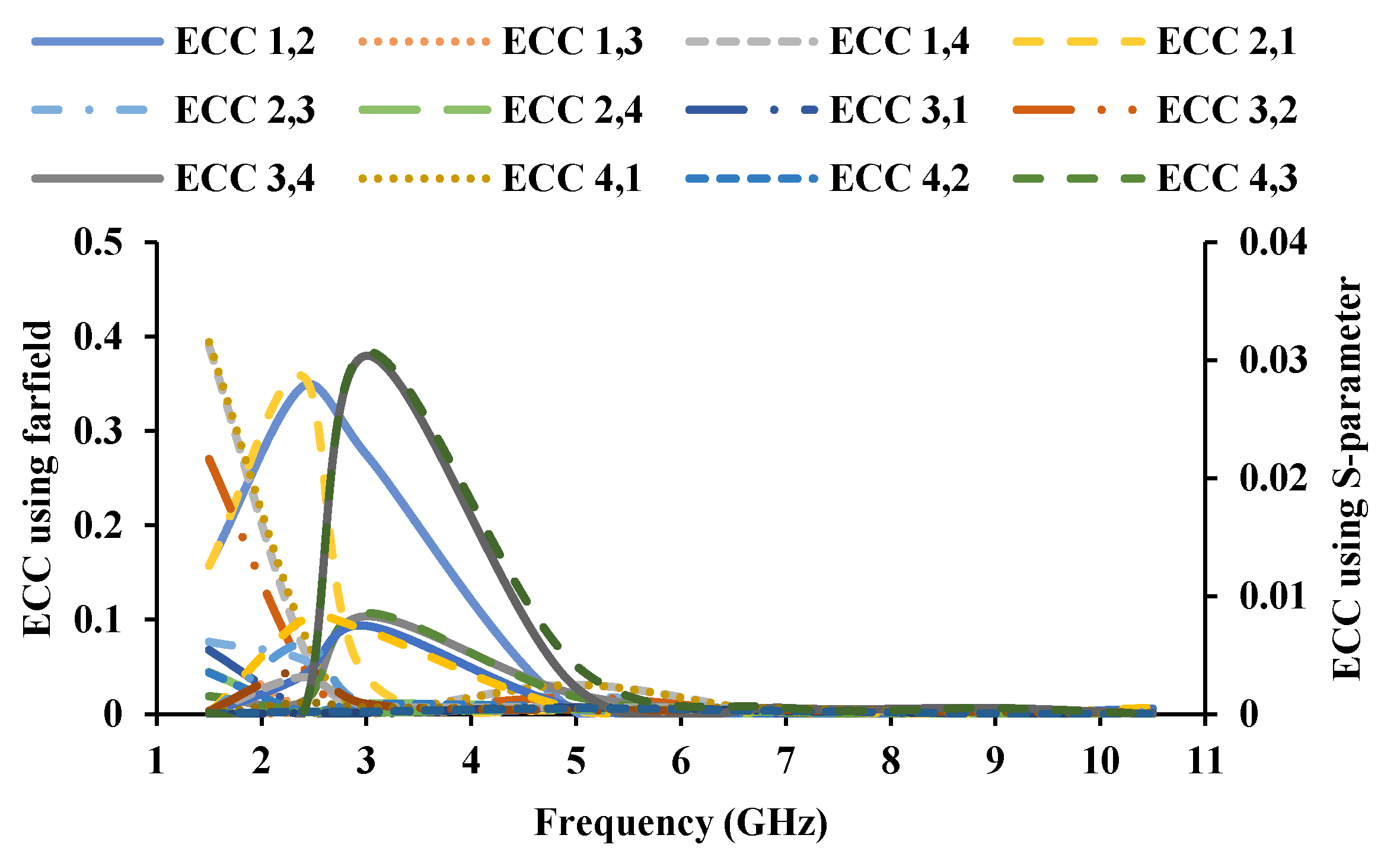
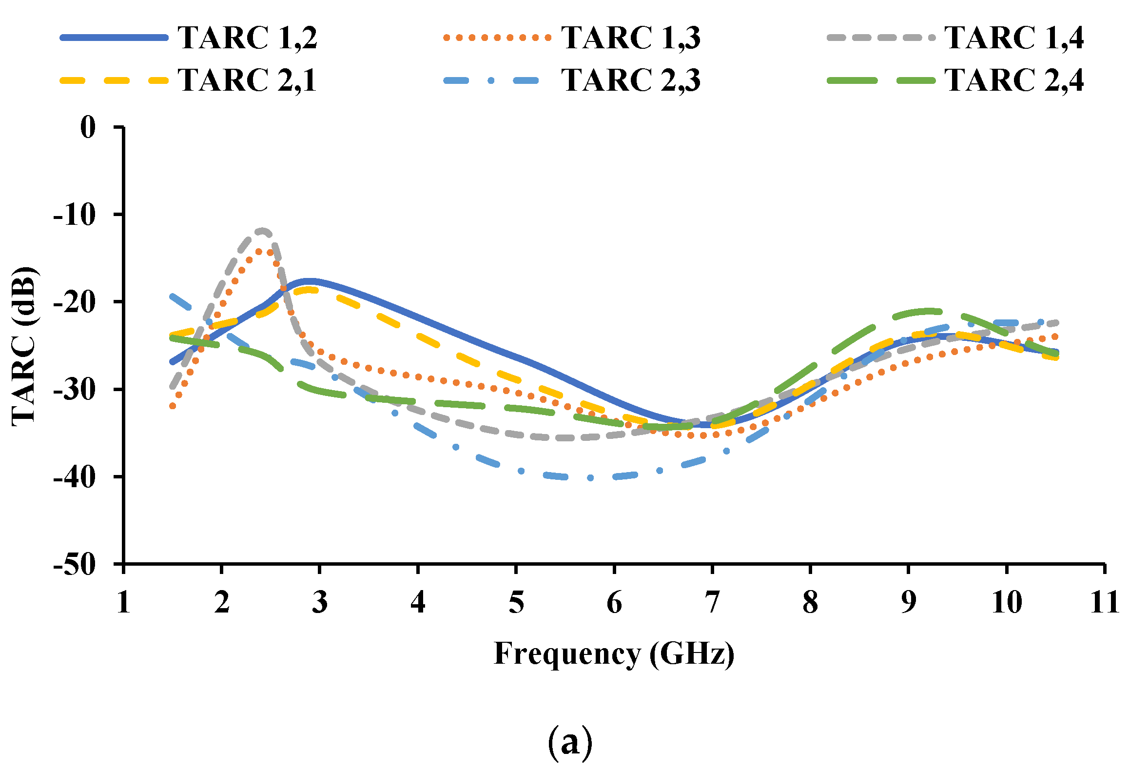
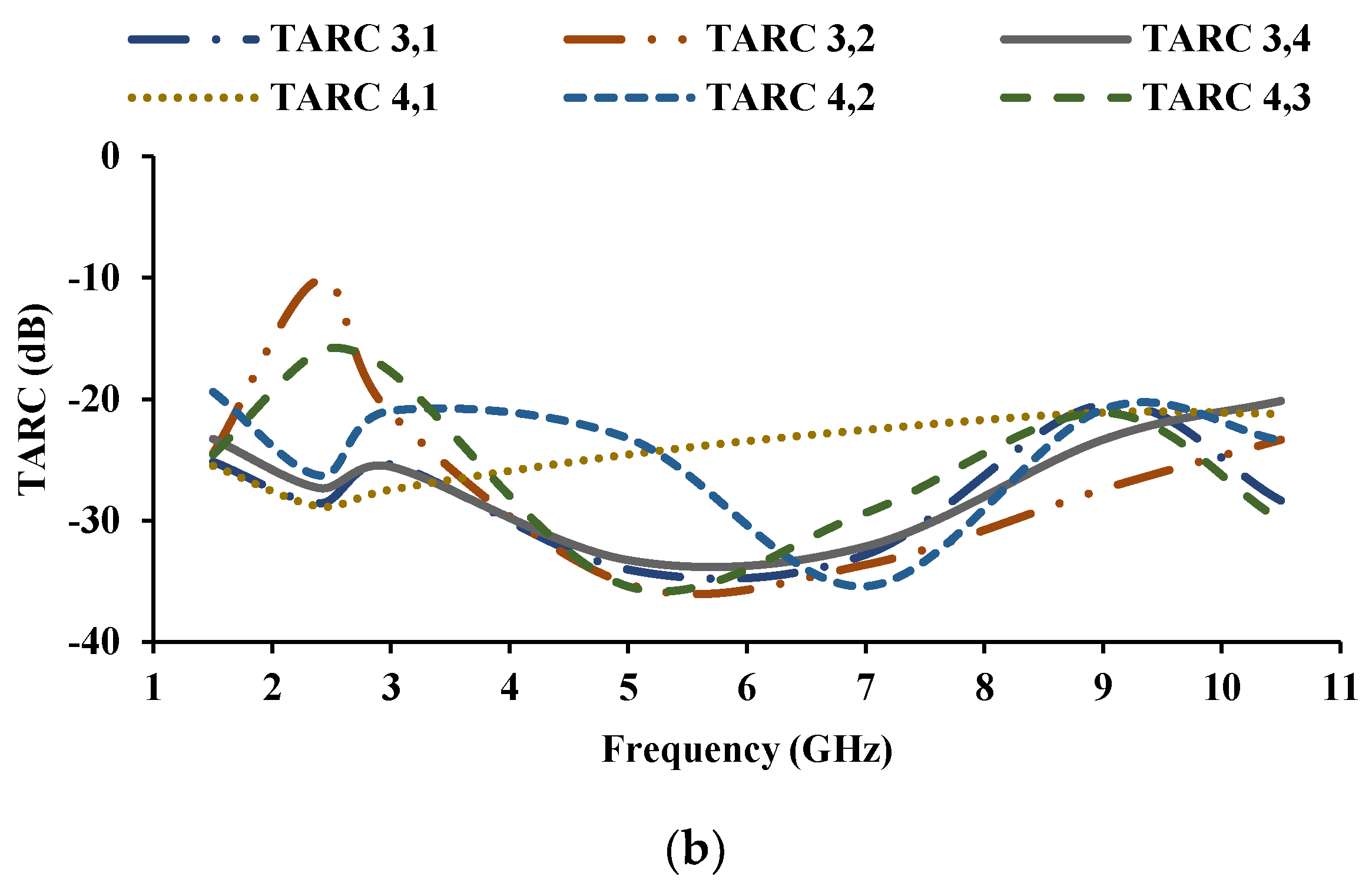
3. Radiation and Diversity Characteristics
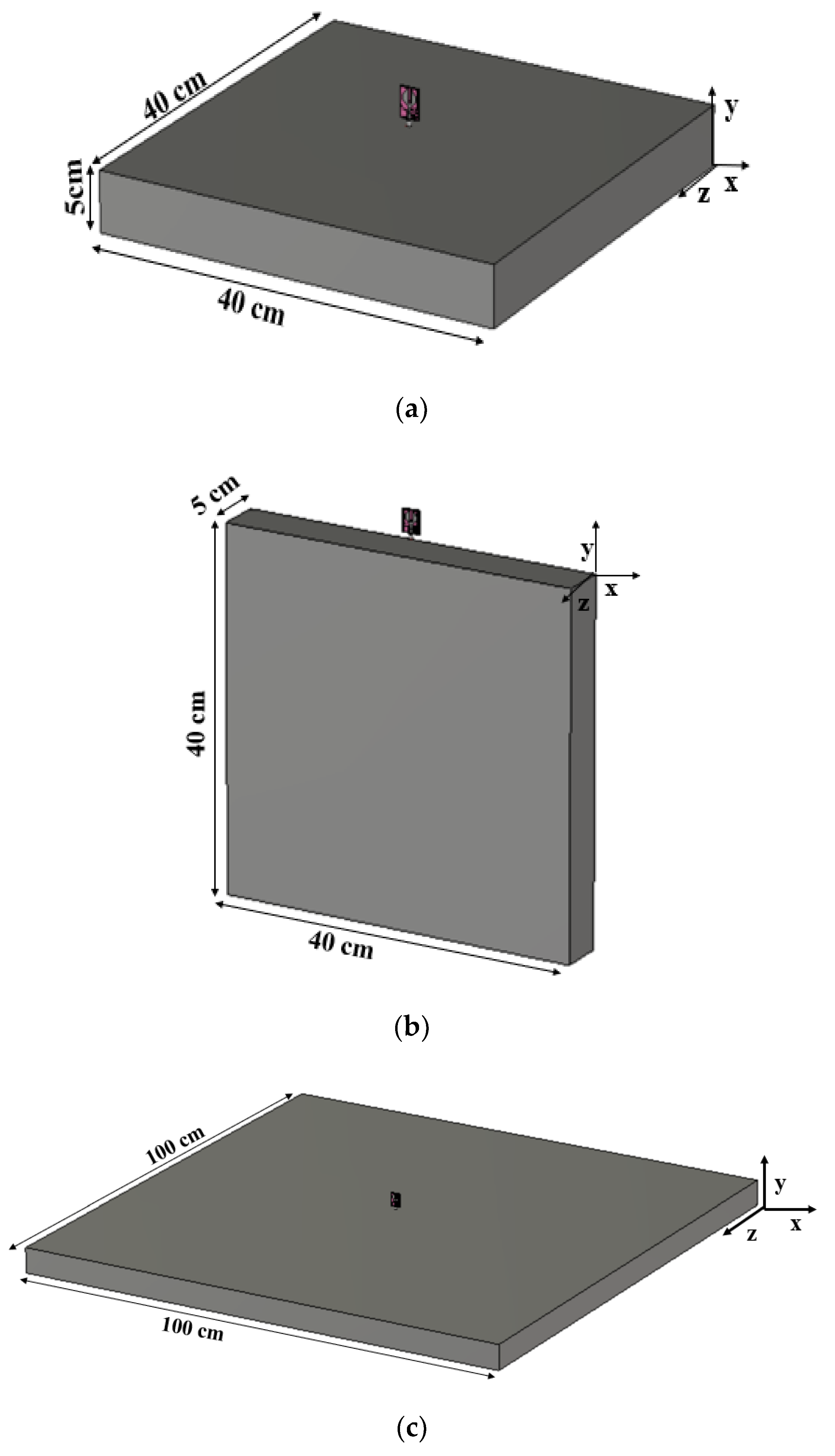
4. Housing Effect
5. On-Car Scenario
- The multiband operation is achieved in the proposed prototype without any need for reconfigurability.
- The orthogonal configuration of the antenna provides additional polarization and covers signals from all directions.
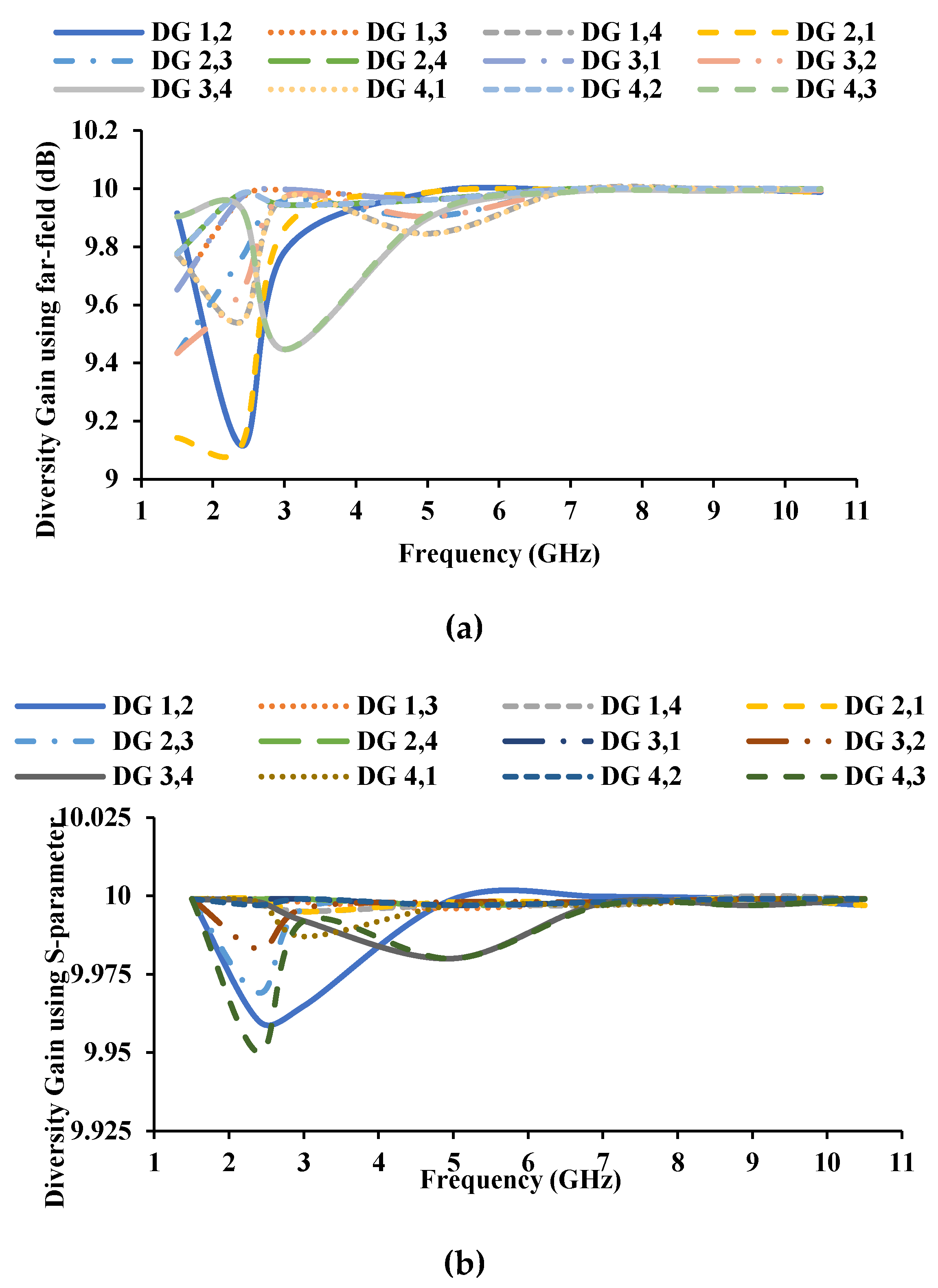
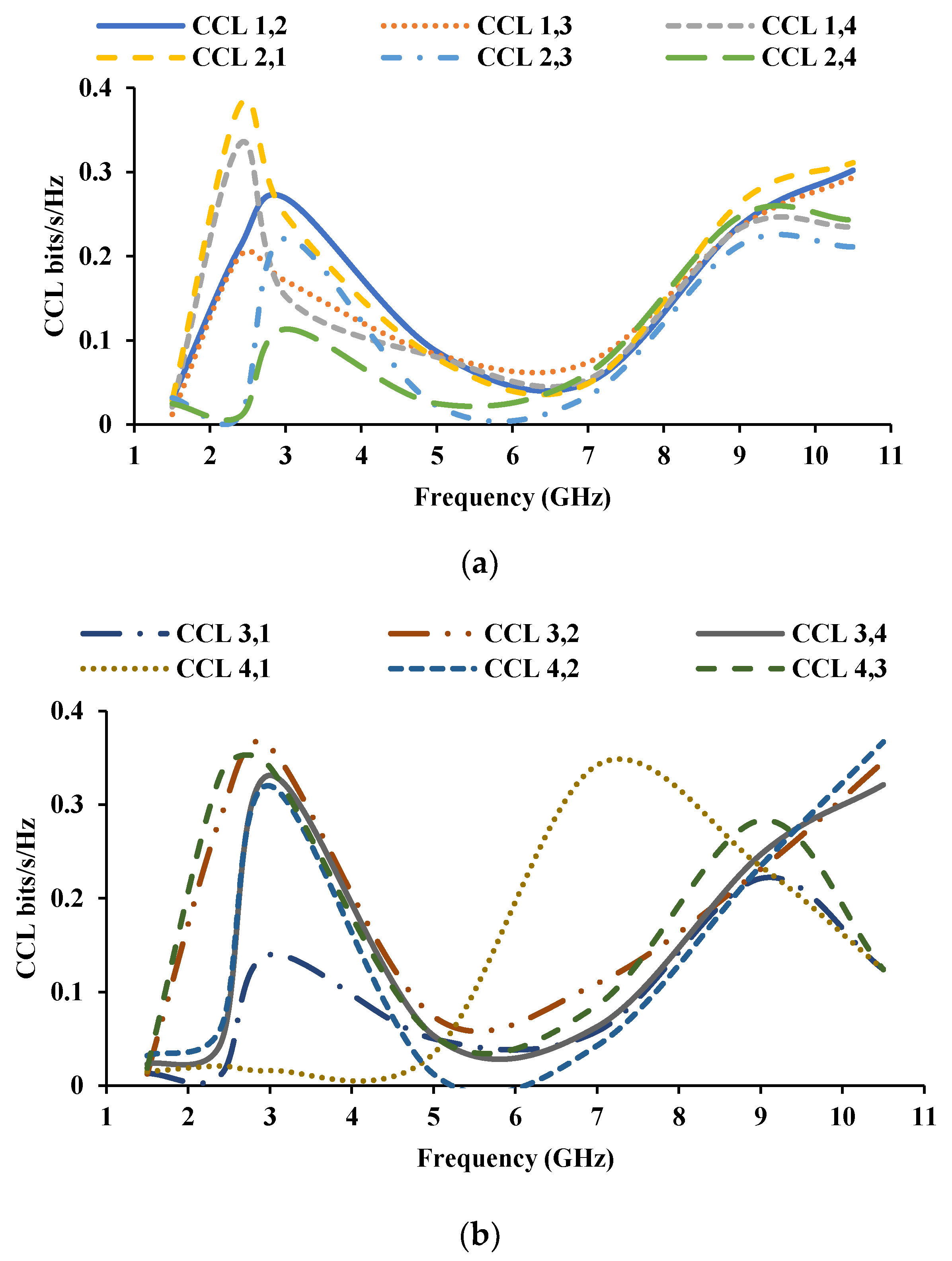
- The MIMO antenna diversity performance is investigated using parameters such as ECC, DG, TARC, and CCL, and the calculated values are found in the acceptable limits.
- The proposed antenna is tested in an automotive environment, and the results show that the performance of the proposed antenna is stable.
6. Conclusions
Author Contributions
Funding
Institutional Review Board Statement
Informed Consent Statement
Data Availability Statement
Conflicts of Interest
References
- Alsath, M.G.N.; Kanagasabai, M. Planar pentaband antenna for vehicular communication application. IEEE Antennas Wirel. Propag. Lett. 2014, 13, 110–113. [Google Scholar] [CrossRef]
- Madhav, B.T.P.; Anilkumar, T.; Kotamraju, S.K. Transparent and conformal wheel-shaped fractal antenna for vehicular communication applications. AEU-Int. J. Electron. Commun. 2018, 91, 1–10. [Google Scholar] [CrossRef]
- Malathy, E.M.; Praveen Joe, I.R.; Ajitha, P. Miniaturized dual-band metamaterial-loaded antenna for heterogeneous vehicular communication networks. IETE J. Res. 2021, 1–10. [Google Scholar] [CrossRef]
- Kola, K.S.; Chatterjee, A. Design of a right-handed circularly polarized printed antenna for vehicular communication. Wirel. Pers. Commun. 2021, 1–22. [Google Scholar] [CrossRef]
- Madhav, B.T.P.; Anilkumar, T. Design and study of multiband planar wheel-like fractal antenna for vehicular communication applications. Microw. Opt. Technol. Lett. 2021, 60, 1985–1993. [Google Scholar] [CrossRef]
- Raheja, D.K.; Kumar, S.; Kanaujia, B.K. Compact quasi-elliptical-self-complementary four-port super-wideband MIMO antenna with dual band elimination characteristics. AEU-Int. J. Electron. Commun. 2020, 114, 153001. [Google Scholar] [CrossRef]
- Kumar, S.; Lee, G.H.; Kim, D.H.; Choi, H.C.; Kim, K.W. Dual circularly polarized planar four-port MIMO antenna with wide axial-ratio bandwidth. Sensors 2020, 20, 5610. [Google Scholar] [CrossRef] [PubMed]
- Srivastava, K.; Kanaujia, B.K.; Dwari, S.; Kumar, S.; Khan, T. 3D cuboidal design MIMO/diversity antenna with band notched characteristics. AEU-Int. J. Electron. Commun. 2019, 108, 141–147. [Google Scholar] [CrossRef]
- Raheja, D.K.; Kanaujia, B.K.; Kumar, S. Low profile four-port super-wideband multiple-input-multiple-output antenna with triple band rejection characteristics. AEU-Int. J. Electron. Commun. 2019, 29, 21831. [Google Scholar] [CrossRef]
- Khan, A.; Bashir, S.; Ghafoor, S.; Qureshi, K.K. Mutual coupling reduction using ground stub and EBG in a compact wideband MIMO-antenna. IEEE Access 2021, 9, 40972–40979. [Google Scholar] [CrossRef]
- Sun, L.; Li, Y.; Zhang, Z.; Wang, H. Self-decoupled MIMO antenna pair with shared radiator for 5G smartphones. IEEE Trans. Antennas Propag. 2020, 68, 3423–3432. [Google Scholar] [CrossRef]
- Iqbal, A.; Altaf, A.; Abdullah, M.; Alibakhshikenari, M.; Limiti, E.; Kim, S. Modified u-shaped resonator as decoupling structure in MIMO antenna. Electronics 2020, 9, 1321. [Google Scholar] [CrossRef]
- Faraz, F.; Chen, X.; Li, Q.; Tang, J.; Li, J.; Khan, T.A.; Zhang, X. Mutual coupling reduction of dual polarized low profile MIMO antenna using decoupling resonators. Appl. Comput. Electromagn. Soc. J. 2020, 35, 38–43. [Google Scholar]
- Sakli, H.; Abdelhamid, C.; Essid, C.; Sakli, N. Metamaterial-based antenna performance enhancement for MIMO system applications. IEEE Access 2021, 9, 38546–38556. [Google Scholar] [CrossRef]
- Kaur, N.; Sivia, J.S.; Kumar, M. SRR and rectangular stubs loaded novel fractal antenna realization for multiband wireless applications. Wirel. Pers. Commun. 2021, 120, 515–533. [Google Scholar] [CrossRef]
- Rajeshkumar, V.; Rajkumar, R. SRR loaded compact tri-band MIMO antenna for wlan/wimax applications. Prog. Electromagn. Res. Lett. 2020, 95, 43–53. [Google Scholar] [CrossRef]
- Paul, P.M.; Kandasamy, K.; Sharawi, M.S. A multi-band u-strip and SRR loaded slot antenna with circular polarization characteristics. Adv. Electromagn. 2020, 9, 41–48. [Google Scholar] [CrossRef] [Green Version]
- Srivastava, K.; Kumar, S.; Kanaujia, B.K.; Dwari, S. Design and packaging of ultra-wideband multiple-input-multiple-output/diversity antenna for wireless applications. Int. J. RF Microw. Comput. Aided Eng. 2020, 30, e22357. [Google Scholar] [CrossRef]
- Khan, M.S.; Iftikhar, A.; Shubair, R.M.; Capobianco, A.-D.; Braaten, B.D.; Anagnostou, D.E. Eight-Element Compact UWB-MIMO/Diversity Antenna with WLAN Band Rejection for 3G/4G/5G Communications. IEEE Open J. Antennas Propag. 2020, 1, 196–206. [Google Scholar] [CrossRef]
- Maddio, S.; Pelosi, G.; Righini, M.; Selleri, S. A slotted patch antenna with enhanced gain pattern for automotive applications. Prog. Electromagn. Res. Lett. 2021, 95, 135–141. [Google Scholar] [CrossRef]
- Maurya, N.K.; Bhattacharya, R. Design of compact dual-polarized multiband MIMO antenna using near-field for IoT. AEU-Int. J. Electron. Commun. 2020, 117, 153091. [Google Scholar] [CrossRef]
- Dileepan, D.; Natarajan, S.; Rajkumar, R. A high isolation multiband mimo antenna without decoupling structure for wlan/wimax/5g applications. Prog. Electron. Res. C 2021, 112, 207–219. [Google Scholar] [CrossRef]
- Babu, K.V.; Anuradha, B. Design of multi-band minkowski MIMO antenna to reduce the mutual coupling. J. King Saud Univ.-Eng. Sci. 2020, 32, 51–57. [Google Scholar] [CrossRef]
- Jha, K.R.; Jibran, Z.A.P.; Singh, C.; Sharma, S.K. 4-Port MIMO Antenna Using Common Radiator on a Flexible Substrate for Sub-1GHz, Sub-6GHz 5G NR, and Wi-Fi 6 Applications. IEEE Open J. Antennas Propag. 2021, 2, 689–701. [Google Scholar] [CrossRef]
- Huang, J.; Dong, G.; Cai, J.; Li, H.; Liu, G. A quad-port dual-band mimo antenna array for 5 g smartphone applications. Electronics 2021, 10, 542. [Google Scholar] [CrossRef]
- Ayinala, K.D.; Sahu, P.K. A Compact Slit-loaded Modified Slot Antenna Based Quad-port MIMO Antenna for WLAN Applications. In Proceedings of the 7th IEEE Uttar Pradesh Section International Conference on Electrical, Electronics and Computer Engineering (UPCON 2020), Prayagraj, India, 27–29 November 2020; Institute of Electrical and Electronics Engineers Inc.: Piscataway, NJ, USA, 2020. [Google Scholar]
- Naidu, P.V.; Saiharanadh, A.; Maheshbabu, D.; Kumar, A.; Vummadisetty, N. Design and performance analysis of g-shaped compact acs fed 4-port mimo antenna for triple frequency band applications. Prog. Electromagn. Res. C 2021, 112, 55–68. [Google Scholar] [CrossRef]
- Nagendra, R.; Swarnalatha, S. Design and performance of four port MIMO antenna for IOT applications. ICT Express 2021. [Google Scholar] [CrossRef]
- Ray, K.P. Design Aspects of Printed Monopole Antennas for Ultra-Wide Band Applications. Int. J. Antennas Propag. 2008, 2008, 713858. [Google Scholar] [CrossRef]
- Sanyal, R.; Sarkar, P.P.; Sarkar, S. Octagonal nut shaped monopole UWB antenna with sextuple band notched characteristics. AEU-Int. J. Electron. Commun. 2019, 110, 152833. [Google Scholar] [CrossRef]
- Sharma, M.; Awasthi, Y.K.; Singh, H. CPW-fed triple high rejection notched UWB and X-band antenna on silicon for imaging and wireless applications. Int. J. Electron. 2019, 106, 945–959. [Google Scholar] [CrossRef]
- Sharawi, M.S. Current Misuses and Future Prospects for Printed Multiple-Input, Multiple-Output Antenna Systems [Wireless Corner]. IEEE Antennas Propag. Mag. 2017, 59, 162–170. [Google Scholar] [CrossRef]
- Elshirkasi, A.M.; Al-Hadi, A.A.; Mansor, M.F.; Khan, R.; Soh, P.J. Envelope correlation coefficient of a two-port mimo terminal antenna under uniform and gaussian angular power spectrum with user’s hand effect. Prog. Electron. Res. C 2019, 92, 123–136. [Google Scholar] [CrossRef] [Green Version]
- Dkiouak, A.; Zakriti, A.; El Ouahabi, M.; Elftouh, H.; McHbal, A. Design of CPW-fed MIMO antenna for ultra-wideband communications. Procedia Manuf. 2020, 46, 782–787. [Google Scholar] [CrossRef]
- Fritz-Andrade, E.; Jardon-Aguilar, H.; Tirado-Mendez, J.A. The correct application of total active reflection coefficient to evaluate MIMO antenna systems and its generalization to N ports. Int. J. RF Microw. Comput. Aided Eng. 2020, 4, e22113. [Google Scholar] [CrossRef]
- Sultan, K.S.; Abdullah, H.H. Planar UWB MIMO-Diversity Antenna with Dual Notch Characteristics. Prog. Electron. Res. C 2019, 93, 119–129. [Google Scholar] [CrossRef] [Green Version]
- Ramanujam, P.; Venkatesan, P.G.R.; Arumugam, C.; Ponnusamy, M. Design of a compact printed lowpass filtering antenna with wideband harmonic suppression for automotive communication. Int. J. RF Microw. Comput. Aided Eng. 2020, 30, e22452. [Google Scholar] [CrossRef]
- Ojaroudi Parchin, N.; Jahanbakhsh Basherlou, H.; I A Al-Yasir, Y.; M Abdulkhaleq, A.; A Abd-Alhameed, R. Ultra-Wideband Diversity MIMO Antenna System for Future Mobile Handsets. Sensors 2020, 20, 2371. [Google Scholar] [CrossRef]
- Agarwal, M.; Dhanoa, J.K.; Khandelwal, M.K. Ultrawide band two-port MIMO diversity antenna with triple notch bands, stable gain and suppressed mutual coupling. AEU-Int. J. Electron. Commun. 2020, 120, 153225. [Google Scholar] [CrossRef]
- Khalid, M.; Iffat Naqvi, S.; Hussain, N.; Rahman, M.; Mirjavadi, S.S.; Khan, M.J.; Amin, Y. 4-port MIMO antenna with defected ground structure for 5G millimeter wave applications. Electronics 2020, 9, 71. [Google Scholar] [CrossRef] [Green Version]
- Kumar, S.; Lee, G.H.; Kim, D.H.; Mohyuddin, W.; Choi, H.C.; Kim, K.W. A compact four-port UWB MIMO antenna with connected ground and wide axial ratio bandwidth. Int. J. Microw. Wirel. Technol. 2020, 12, 75–85. [Google Scholar] [CrossRef]
- Mathur, R.; Dwari, S. Compact 4-port MIMO/Diversity antenna with low correlation for UWB application. Frequenz 2018, 72, 429–435. [Google Scholar] [CrossRef]
- Premalatha, J.; Sheela, D. Compact four-port vertically polarized UWB monopole antenna for MIMO communications. Circuit World 2020, 47, 129–137. [Google Scholar]
- Naktong, W.; Ruengwaree, A. Four-port rectangular monopole antenna for UWB-MIMO. Prog. Electron. Res. B 2020, 87, 19–38. [Google Scholar] [CrossRef]
- Mathur, R.; Dwari, S. Compact 4-Port UWB-MIMO slot antenna with dual polarization and low correlation for spatial diversity application. Frequenz 2018, 72, 503–509. [Google Scholar] [CrossRef]
- Luo, S.; Wang, D.; Chen, Y.; Li, E.; Jiang, C. A compact dual-port UWB-MIMO antenna with quadruple band-notched characteristics. AEU-Int. J. Electron. Commun. 2021, 136, 153770. [Google Scholar] [CrossRef]
- Nikam, B.V.; Jadhav, M.R. A compact quad-port band-notched MIMO antenna for Wi-MAX application with low mutual coupling. Prog. Electromagn. Res. C 2020, 104, 53–67. [Google Scholar]
- Sudarsan, H.; Gayathri, R.; Mahendran, K. A novel square fractal dual port MIMO antenna with tri band rejection capabilities. J. Ambient. Intell. Humaniz. Comput. 2021, 1–18. [Google Scholar] [CrossRef]
- Kumar, P.; Urooj, S.; Alrowais, F. Design and implementation of quad-port MIMO antenna with dual-band elimination characteristics for ultra-wideband applications. Appl. Sci. 2020, 10, 1715. [Google Scholar] [CrossRef] [Green Version]
- Arumugam, S.; Manoharan, S.; Palaniswamy, S.K.; Kumar, S. Design and performance analysis of a compact quad-element uwb mimo antenna for automotive communications. Electronics 2021, 10, 2184. [Google Scholar] [CrossRef]
- Kumar, P.; Urooj, S.; Malibari, A. Design of quad-port ultra-wideband multiple-input-multiple-output antenna with wide axial-ratio bandwidth. Sensors 2020, 20, 1174. [Google Scholar] [CrossRef] [Green Version]
- Khan, A.A.; Naqvi, S.A.; Khan, M.S.; Ijaz, B. Quad port miniaturized MIMO antenna for UWB 11 GHz and 13 GHz frequency bands. AEU-Int. J. Electron. Commun. 2021, 131, 153618. [Google Scholar] [CrossRef]
- Agarwal, M.; Dhanoa, J.K.; Khandelwal, M.K. Two-port hexagon shaped MIMO microstrip antenna for UWB applications integrated with double stop bands for WiMax and WLAN. AEU-Int. J. Electron. Commun. 2021, 138, 153885. [Google Scholar] [CrossRef]
- Yalavarthi, U.D. Reconfigurable orthogonal quad-port MIMO antenna for DSRC, WLAN, RADAR and Ku-band applications. AEU-Int. J. Electron. Commun. 2021, 136, 153766. [Google Scholar] [CrossRef]
- Abd El-Hameed, A.S.; Wahab, M.G.; Elshafey, N.A.; Elpeltagy, M.S. Quad-Port UWB MIMO antenna based on LPF with vast rejection band. AEU-Int. J. Elect. Commun. 2021, 134, 153712. [Google Scholar] [CrossRef]


| Dimension | Value (mm) | Dimension | Value (mm) |
|---|---|---|---|
| L1 | 1.7 | S4 | 6.9 |
| L2 | 2.75 | S5 | 1.7 |
| L3 | 10.6 | S6 | 5.5 |
| L4 | 8.05 | S7 | 1.7 |
| L5 | 22.3 | S8 | 5.5 |
| L6 | 1.9 | S9 | 1.85 |
| L7 | 6.7 | S10 | 4.8 |
| L8 | 6.5 | S11 | 2.35 |
| L9 | 4.3 | S12 | 4.8 |
| S1 | 12.3 | S13 | 2.1 |
| S2 | 8.15 | S14 | 5.4 |
| S3 | 24.5 | S15 | 14.75 |
| Frequency (GHz) | R (Ω) | C (pF) | L (nH) |
|---|---|---|---|
| 1.53 | 38.93 | 23.55 | 0.459 |
| 2.43 | 55.11 | 13.38 | 0.321 |
| 4.504 | 50.6 | 0.44 | 2.837 |
| 8.656 | 50.39 | 0.0739 | 4.571 |
| Ref. | Bandwidth (GHz) | Dimensions (λ0 × λ0) | Substrate | Peak Gain (dBi) | Efficiency (%) | DG (dB) | ECC | Polarization |
|---|---|---|---|---|---|---|---|---|
| [38] | 2–11 | 0.22 × 0.22 | FR-4 | 3 | 75 | 10 | <0.5 | Dual |
| [39] | 3.1–10.6 | 0.39 × 0.39 | FR-4 | 5 | --- | 10 | <0.02 | Dual |
| [40] | 25.5–29.6 | 2.5 × 2.97 | Rogers RO4350B | 8.3 | 82 | >9.96 | <0.01 | Dual |
| [41] | 3.1–11 | 0.46 × 0.46 | FR-4 | 5.5 | --- | >9.9 | <0.015 | Vertical |
| [42] | 3.2–11 | 0.38 × 0.38 | FR-4 | 4 | >70 | >9 (ADG) | <0.5 | Dual |
| [43] | 2.2–12.3 | 0.19 × 0.19 | FR-4 | 5.82 | 87 | >8 (ADG), >7.5 (EDG) | <0.3 | Vertical |
| [44] | 3.1–10.6 | 0.82 × 0.82 | FR-4 | 3.38 | >85.7 | --- | <0.001 | Dual |
| [45] | 3.1–11.9 | 0.37 × 0.37 | FR-4 | 6 | >78 | >9.96 | <0.03 | Dual |
| [46] | 3–11 | 0.39 × 0.3 | Rogers 5880 | 5.8 | - | >9.8 | <0.02 | Vertical |
| [47] | 5.1–5.8 | 0.85 × 0.85 | FR-4 | 2.9 | >70 | >9.9 | <0.0006 | Dual |
| [48] | 2.35–9.04 | 0.51 × 0.27 | FR-4 | 3 | - | 8 | <0.5 | Vertical |
| [49] | 3–16 | 0.58 × 0.58 | FR-4 | 7 | - | - | <0.07 | Dual |
| [50] | 3.14–12.24 | 0.524 × 0.524 | Rogers 3003 | 5.1 | >81 | >9.6 | <0.004 | Dual |
| [51] | 3.8–6.5 | 0.57 × 0.57 | FR-4 | 6.8 | >60 | - | <0.04 | Circular |
| [52] | 3–13.5 | 0.4 × 0.4 | TMM4 laminate | 3.5 | >89 | >9.95 | <0.4 | Dual |
| [53] | 2.1–11.4 | 0.24 × 0.32 | FR-4 | 1.2 | >75 | >9.9 | <0.04 | Dual |
| [54] | 5.5–9.2, 13.2–17.9, 11.5–14.6 | 0.733 × 0.733 | FR-4 | 7.57 dB | >70 | >9.9 | <0.05 | Dual |
| [55] | 2.15–20 | 0.308 × 0.308 | FR-4 | 6.7 | >60 | >9.96 | <0.01 | Dual |
| This work | 1.41–1.62, 2.4–2.462, 3.1–12.8 | 0.2 × 0.2 | FR-4 | 2.14 | 87 | >9 | <0.4 | Dual |
Publisher’s Note: MDPI stays neutral with regard to jurisdictional claims in published maps and institutional affiliations. |
© 2021 by the authors. Licensee MDPI, Basel, Switzerland. This article is an open access article distributed under the terms and conditions of the Creative Commons Attribution (CC BY) license (https://creativecommons.org/licenses/by/4.0/).
Share and Cite
Kannappan, L.; Palaniswamy, S.K.; Wang, L.; Kanagasabai, M.; Kumar, S.; Alsath, M.G.N.; Rao, T.R. Quad-Port Multiservice Diversity Antenna for Automotive Applications. Sensors 2021, 21, 8238. https://doi.org/10.3390/s21248238
Kannappan L, Palaniswamy SK, Wang L, Kanagasabai M, Kumar S, Alsath MGN, Rao TR. Quad-Port Multiservice Diversity Antenna for Automotive Applications. Sensors. 2021; 21(24):8238. https://doi.org/10.3390/s21248238
Chicago/Turabian StyleKannappan, Lekha, Sandeep Kumar Palaniswamy, Lulu Wang, Malathi Kanagasabai, Sachin Kumar, Mohammed Gulam Nabi Alsath, and Thipparaju Rama Rao. 2021. "Quad-Port Multiservice Diversity Antenna for Automotive Applications" Sensors 21, no. 24: 8238. https://doi.org/10.3390/s21248238
APA StyleKannappan, L., Palaniswamy, S. K., Wang, L., Kanagasabai, M., Kumar, S., Alsath, M. G. N., & Rao, T. R. (2021). Quad-Port Multiservice Diversity Antenna for Automotive Applications. Sensors, 21(24), 8238. https://doi.org/10.3390/s21248238