Planetary Gearbox Dynamic Modeling Considering Bearing Clearance and Sun Gear Tooth Crack †


Abstract
1. Introduction
2. Proposed Methodology
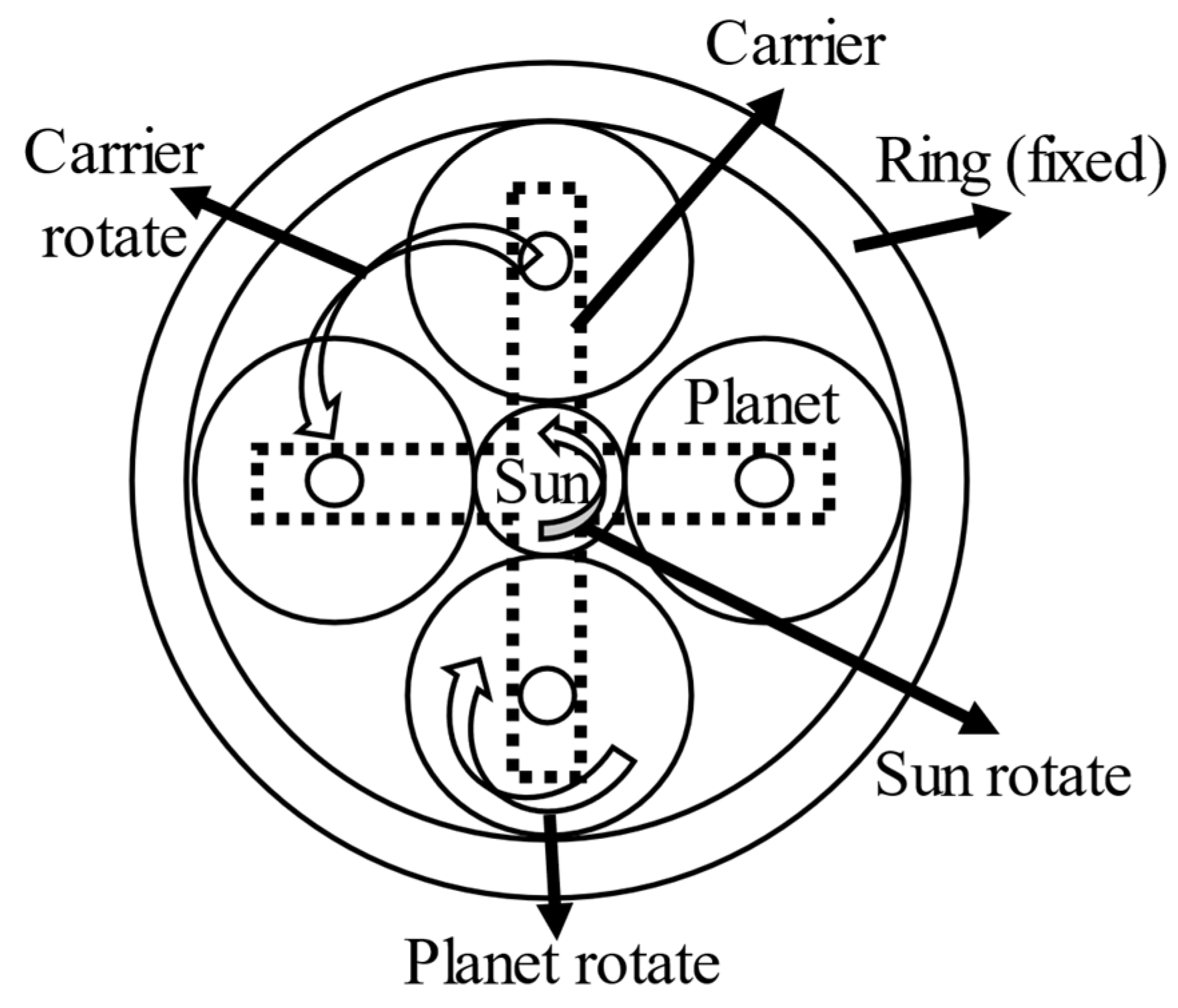
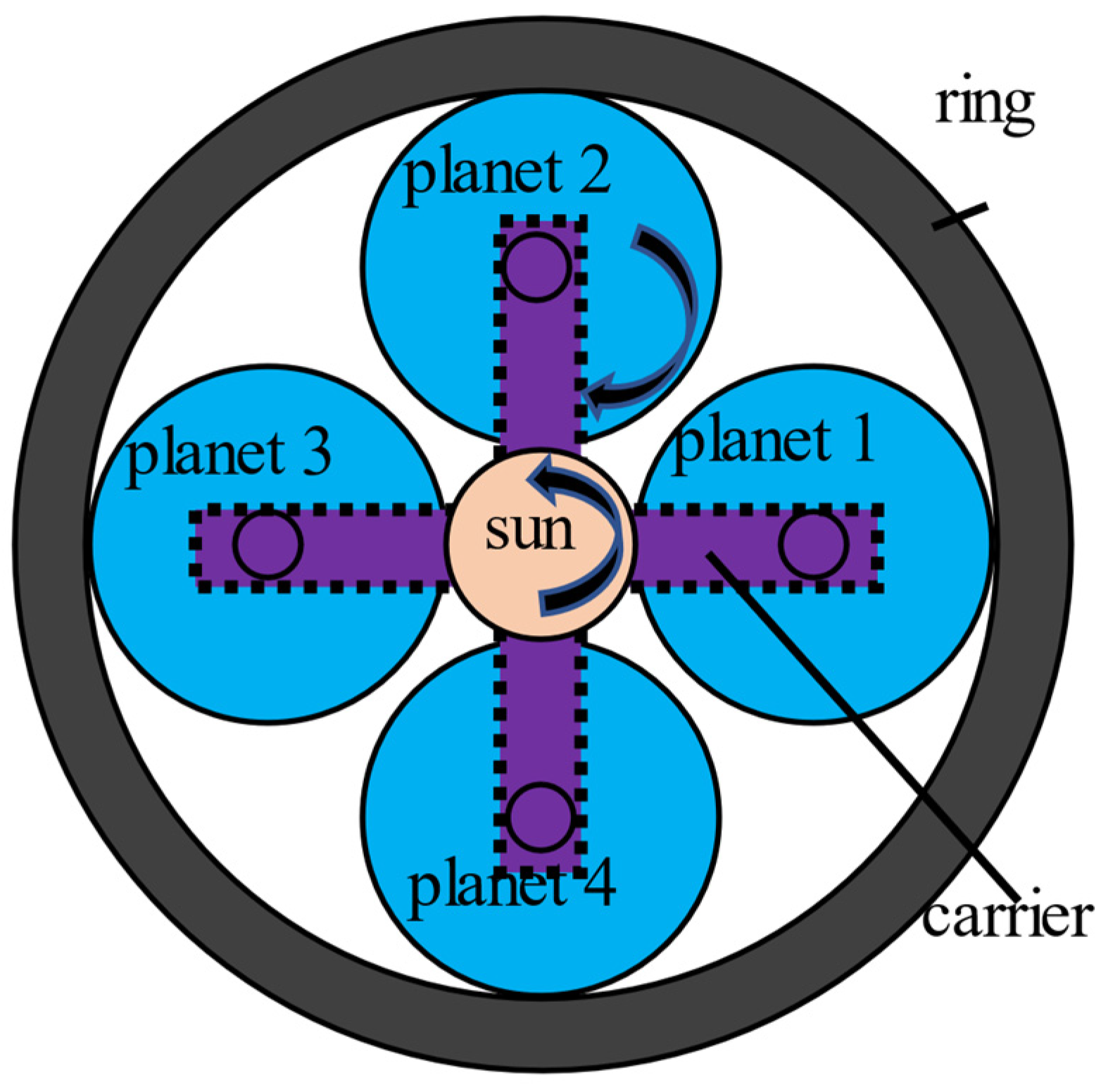
2.1. Planetary Gearbox System
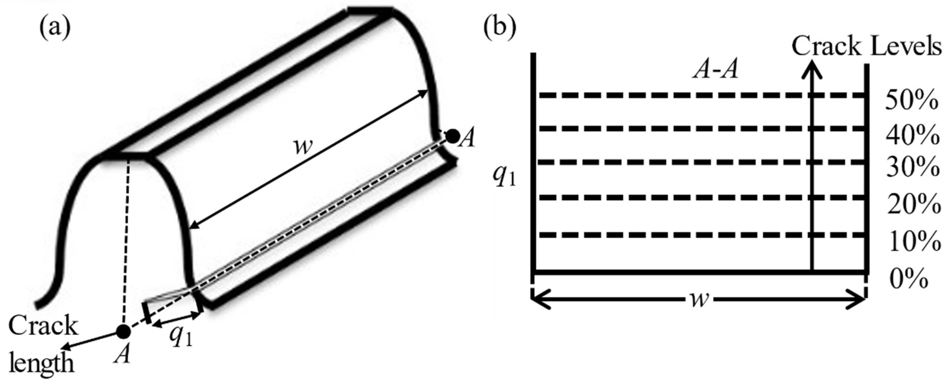
2.2. Sun Gear Tooth Crack Modeling
2.3. Bearing Clearance Modeling
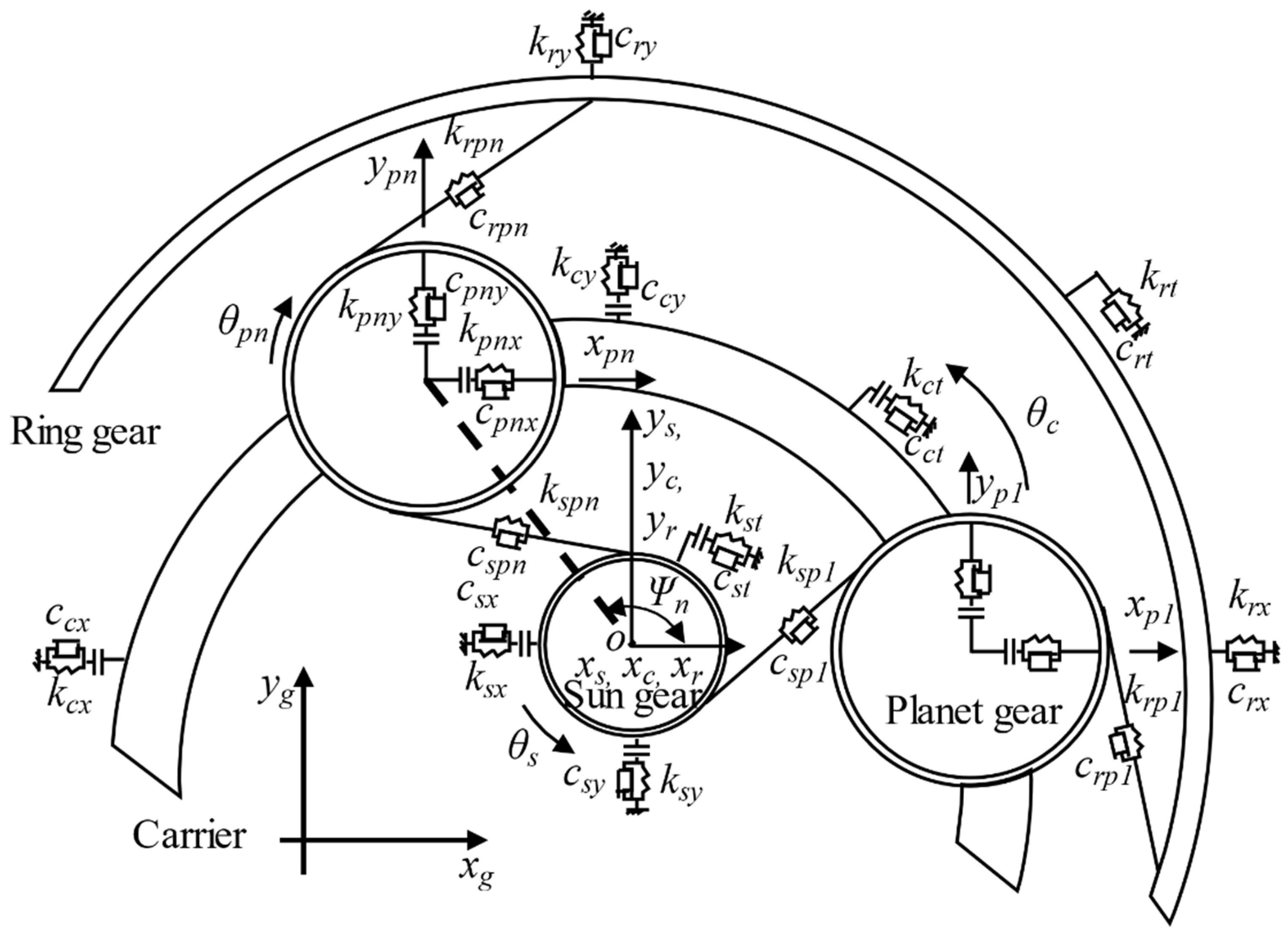
2.4. Motion Equations
3. Results and Discussions
3.1. Single Type of Bearing Clearance
3.2. Combinations of Multiple Bearing Clearance Types
4. Conclusions
Author Contributions
Funding
Institutional Review Board Statement
Informed Consent Statement
Conflicts of Interest
References
- Lei, Y.; Lin, J.; Zuo, M.J.; He, Z. Condition Monitoring and Fault Diagnosis of Planetary Gearboxes: A Review. Measurement 2014, 48, 292–305. [Google Scholar] [CrossRef]
- Liang, X.; Zuo, M.J.; Liu, L. A Windowing and Mapping Strategy for Gear Tooth Fault Detection of a Planetary Gearbox. Mech. Syst. Signal Process. 2016, 80, 445–459. [Google Scholar] [CrossRef]
- Zhao, M.; Kang, M.; Tang, B.; Pecht, M. Deep Residual Networks with Dynamically Weighted Wavelet Coefficients for Fault Diagnosis of Planetary Gearboxes. IEEE Trans. Ind. Electron. 2018, 65, 4290–4300. [Google Scholar] [CrossRef]
- Yang, W.; Tavner, P.J.; Crabtree, C.J.; Feng, Y.; Qiu, Y. Wind Turbine Condition Monitoring: Technical and Commercial Challenges. Wind Energy 2014, 17, 673–693. [Google Scholar] [CrossRef]
- Yang, W.; Court, R.; Jiang, J. Wind Turbine Condition Monitoring by the Approach of SCADA Data Analysis. Renew. Energy 2013, 53, 365–376. [Google Scholar] [CrossRef]
- Qiao, W.; Lu, D. A Survey on Wind Turbine Condition Monitoring and Fault Diagnosis—Part II: Signals and Signal Processing Methods. IEEE Trans. Ind. Electron. 2015, 62, 6546–6557. [Google Scholar] [CrossRef]
- Tang, B.; Liu, W.; Song, T. Wind Turbine Fault Diagnosis Based on Morlet Wavelet Transformation and Wigner-Ville Distribution. Renew. Energy 2010, 35, 2862–2866. [Google Scholar] [CrossRef]
- Leahy, K.; Hu, I.C.; Konstantakopoulos, C.J.; Spanos, A.M. Agogino Diagnosing Wind Turbine Faults Using Machine Learning Techniques Applied to Operational Data. In Proceedings of the 2016 IEEE international conference on prognostics and health management (icphm), Ottawa, ON, Canada, 20 June 2016; pp. 1–8. [Google Scholar]
- Stetco, A.; Dinmohammadi, F.; Zhao, X.; Robu, V.; Flynn, D.; Barnes, M.; Keane, J.; Nenadic, G. Machine Learning Methods for Wind Turbine Condition Monitoring: A Review. Renew. Energy 2019, 133, 620–635. [Google Scholar] [CrossRef]
- Chen, C.; Sun, C.; Zhang, Y.; Wang, N. Fault Diagnosis for Large-Scale Wind Turbine Rolling Bearing Using Stress Wave and Wavelet Analysis. In Proceedings of the 2005 International Conference on Electrical Machines and Systems, Nanjing, China, 27–29 September 2005; Volume 3, pp. 2239–2244. [Google Scholar]
- Teng, W.; Ding, X.; Zhang, X.; Liu, Y.; Ma, Z. Multi-Fault Detection and Failure Analysis of Wind Turbine Gearbox Using Complex Wavelet Transform. Renew. Energy 2016, 93, 591–598. [Google Scholar] [CrossRef]
- Yang, W.; Court, R.; Tavner, P.J.; Crabtree, C.J. Bivariate Empirical Mode Decomposition and Its Contribution to Wind Turbine Condition Monitoring. J. Sound Vib. 2011, 330, 3766–3782. [Google Scholar] [CrossRef]
- Kusiak, A.; Li, W. The Prediction and Diagnosis of Wind Turbine Faults. Renew. Energy 2011, 36, 16–23. [Google Scholar] [CrossRef]
- Chen, X.; Yang, X.; Zuo, M.J.; Tian, Z. Dynamic Modeling of a Planetary Gearbox with Sun Gear Crack and Bearing Clearance. In Proceedings of the 2020 Asia-Pacific International Symposium on Advanced Reliability and Maintenance Modeling (APARM), Vancouver, BC, Canada, 20–23 August 2020; pp. 1–6. [Google Scholar]
- Brumercik, F.; Lukac, M.; Caban, J.; Krzysiak, Z.; Glowacz, A. Comparison of Selected Parameters of a Planetary Gearbox with Involute and Convex–Concave Teeth Flank Profiles. Appl. Sci. 2020, 10, 1417. [Google Scholar] [CrossRef]
- Berri, P.C.; Dalla Vedova, M.D.L.; Maggiore, P.; Riva, G. Design and Development of a Planetary Gearbox for Electromechanical Actuator Test Bench through Additive Manufacturing. Actuators 2020, 9, 35. [Google Scholar] [CrossRef]
- Chaari, F.; Baccar, W.; Abbes, M.S.; Haddar, M. Effect of Spalling or Tooth Breakage on Gearmesh Stiffness and Dynamic Response of a One-Stage Spur Gear Transmission. Eur. J. Mech. A Solids 2008, 27, 691–705. [Google Scholar] [CrossRef]
- Gelman, L.; Zimroz, R.; Birkel, J.; Leigh-Firbank, H.; Simms, D.; Waterland, B.; Whitehurst, G. Adaptive Vibration Condition Monitoring Technology for Local Tooth Damage in Gearboxes. Insight Non-Destr. Test. Cond. Monit. 2005, 47, 461–464. [Google Scholar] [CrossRef][Green Version]
- Chaari, F.; Fakhfakh, T.; Haddar, M. Dynamic Analysis of a Planetary Gear Failure Caused by Tooth Pitting and Cracking. J. Fail. Anal. Prev. 2006, 6, 73–78. [Google Scholar] [CrossRef]
- Liang, X.; Zuo, M.J.; Pandey, M. Analytically Evaluating the Influence of Crack on the Mesh Stiffness of a Planetary Gear Set. Mech. Mach. Theory 2014, 76, 20–38. [Google Scholar] [CrossRef]
- Chaari, F.; Fakhfakh, T.; Haddar, M. Analytical Modelling of Spur Gear Tooth Crack and Influence on Gearmesh Stiffness. Eur. J. Mech. A Solids 2009, 28, 461–468. [Google Scholar] [CrossRef]
- Ma, H.; Song, R.; Pang, X.; Wen, B. Time-Varying Mesh Stiffness Calculation of Cracked Spur Gears. Eng. Fail. Anal. 2014, 44, 179–194. [Google Scholar] [CrossRef]
- Guo, Y.; Keller, J.; Parker, R.G. Nonlinear Dynamics and Stability of Wind Turbine Planetary Gear Sets under Gravity Effects. Eur. J. Mech. A Solids 2014, 47, 45–57. [Google Scholar] [CrossRef]
- Guo, Y.; Parker, R.G. Dynamic Modeling and Analysis of a Spur Planetary Gear Involving Tooth Wedging and Bearing Clearance Nonlinearity. Eur. J. Mech. A Solids 2010, 29, 1022–1033. [Google Scholar] [CrossRef]
- Kahraman, A.; Singh, R. Interactions between Time-Varying Mesh Stiffness and Clearance Non-Linearities in a Geared System. J. Sound Vib. 1991, 146, 135–156. [Google Scholar] [CrossRef]
- Kahraman, A. Load Sharing Characteristics of Planetary Transmissions. Mech. Mach. Theory 1994, 29, 1151–1165. [Google Scholar] [CrossRef]
- Guo, Y.; Parker, R.G. Dynamic Analysis of Planetary Gears With Bearing Clearance. J. Comput. Nonlinear Dyn. 2012, 7. [Google Scholar] [CrossRef]
- Chen, X.; Chen, Y.; Zuo, M.J. Dynamic Modeling of a Planetary Gear System with Sun Gear Crack under Gravity and Carrier-Ring Clearance. Procedia Manuf. 2020, 49, 55–60. [Google Scholar] [CrossRef]
- Liang, X.; Zuo, M.J.; Hoseini, M.R. Vibration Signal Modeling of a Planetary Gear Set for Tooth Crack Detection. Eng. Fail. Anal. 2015, 48, 185–200. [Google Scholar] [CrossRef]
- Liu, L.; Liang, X.; Zuo, M.J. Vibration Signal Modeling of a Planetary Gear Set with Transmission Path Effect Analysis. Measurement 2016, 85, 20–31. [Google Scholar] [CrossRef]
- Mohammed, O.D. Dynamic Modelling and Vibration Analysis for Gear Tooth Crack Detection. Ph.D. Thesis, Luleå Tekniska Universitet, Luleå, Sweden, 2015. [Google Scholar]
- Wu, S.; Zuo, M.J.; Parey, A. Simulation of Spur Gear Dynamics and Estimation of Fault Growth. J. Sound Vib. 2008, 317, 608–624. [Google Scholar] [CrossRef]
- Pandya, Y.; Parey, A. Failure Path Based Modified Gear Mesh Stiffness for Spur Gear Pair with Tooth Root Crack. Eng. Fail. Anal. 2013, 27, 286–296. [Google Scholar] [CrossRef]


| Bevel Gearbox | Stage 1 | Stage 2 | ||||||
|---|---|---|---|---|---|---|---|---|
| Input Gear | Output Gear | Ring Gear | Sun Gear | Planet Gear | Ring Gear | Sun Gear | Planet Gear | |
| No. of teeth | 18 | 72 | 152 | 28 | 62 | 81 | 19 | 31 |
| Reduction ratio | 4.000 | 6.429 | 5.263 | |||||
| Location | Description | Inner Race Diameters (mm) | Outer Race Diameters (mm) | Width (mm) | No. of Rollers |
|---|---|---|---|---|---|
| Sun gear bearing | Timken 42,584/42,381 | 96.838 | 148.4 | 28.58 | 26 |
| Carrier bearing | Timken 42,584/42,381 | 96.838 | 148.4 | 28.58 | 26 |
| Planet gear bearing | NTN 4T-32005X | 25 | 47 | 15 | 19 |
| Crack Levels | 0% | 10% | 20% | 30% | 40% | 50% |
| Crack Length (mm) | 0 | 0.78 | 1.56 | 2.34 | 3.12 | 3.90 |
| Parameters | Sun Gear | Planet Gear | Ring Gear |
|---|---|---|---|
| No. of teeth | 19 | 31 | 81 |
| Module (mm) | 3.2 | 3.2 | 3.2 |
| Pressure Angle (°) | 20 | 20 | 20 |
| Mass (kg) | 0.700 | 1.822 | 5.982 |
| Face width (mm) | 38.1 | 38.1 | 38.1 |
| Young’s Modulus (GPa) | 2.068 × 10⁵ | 2.068 × 10⁵ | 2.068 × 10⁵ |
| Poisson’s ratio | 0.3 | 0.3 | 0.3 |
| Base circle radius (mm) | 28.3 | 46.2 | 120.8 |
| Bearing stiffness (N·m) | ksx = ksy = krx = kry = kcx = kcy = kpnx = kpny = 1.0 × 10⁸ | ||
| Bearing damping (N·s/m) | csx = csy = crx = cry = ccx = ccy = cpnx = cpny = 1.5 × 10³ | ||
| Bearing clearance (mm) | Δc = Δs = 0.080, Δp = 0.035 | ||
| 0% | 10% | 20% | 30% | 40% | 50% | |
|---|---|---|---|---|---|---|
| Case 1 (no bearing clearance) | 2.4 × 10⁻⁶ m | 2.4 × 10⁻⁶ m | 2.9 × 10⁻⁶ m | 3.5 × 10⁻⁶ m | 4.5 × 10⁻⁶ m | 6.3 × 10⁻⁶ m |
| Case 2 (carrier bearing clearance) | 4.9 × 10⁻⁶ m | 5.3 × 10⁻⁶ m | 6.2 × 10⁻⁶ m | 7.8 × 10⁻⁶ m | 10.0 × 10⁻⁶ m | 14.0 × 10⁻⁶ m |
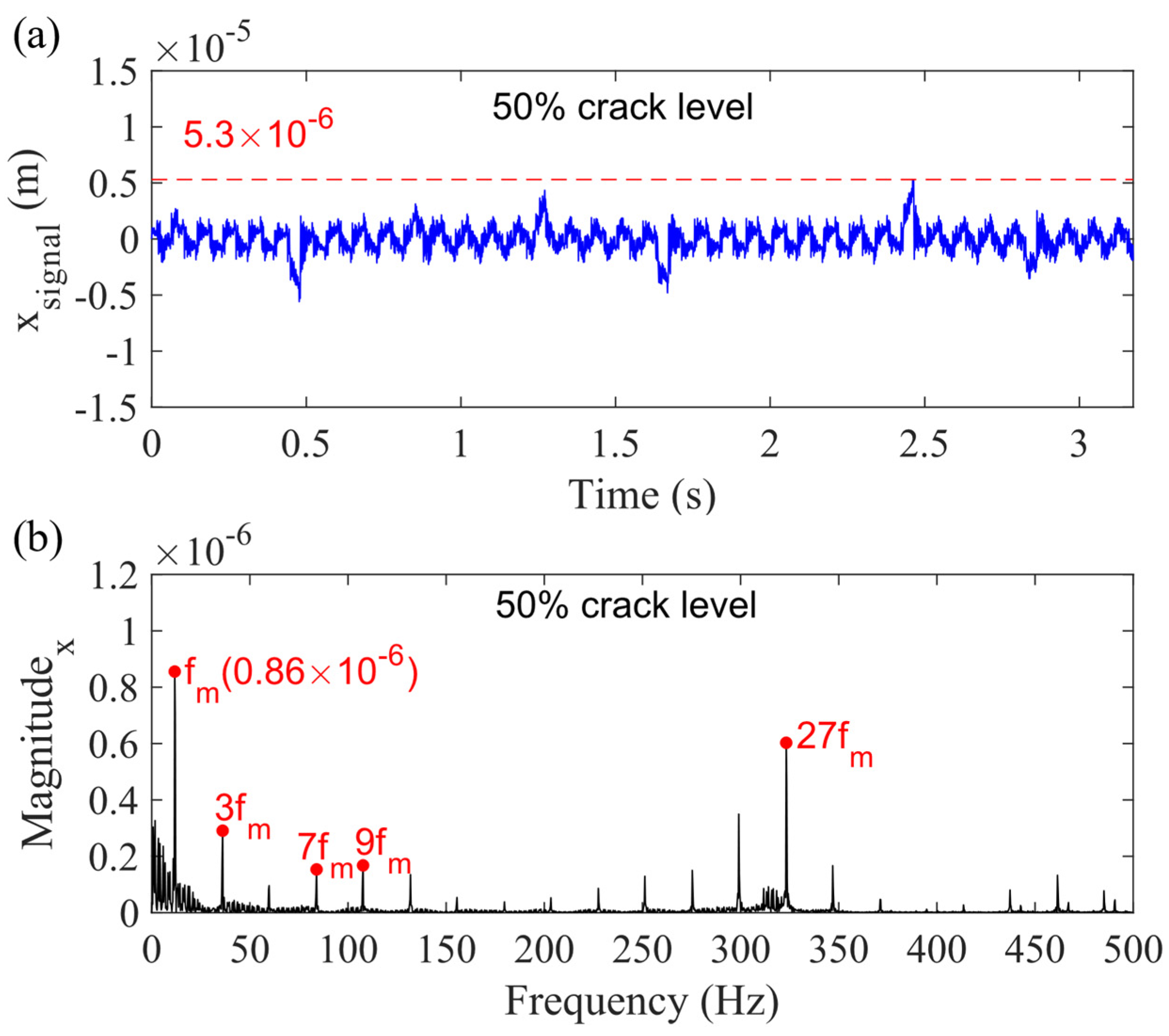
| Case 3 (sun gear bearing clearance) | 2.3 × 10⁻⁶ m | 2.4 × 10⁻⁶ m | 2.8 × 10⁻⁶ m | 3.2 × 10⁻⁶ m | 4.0 × 10⁻⁶ m | 5.3 × 10⁻⁶ m |
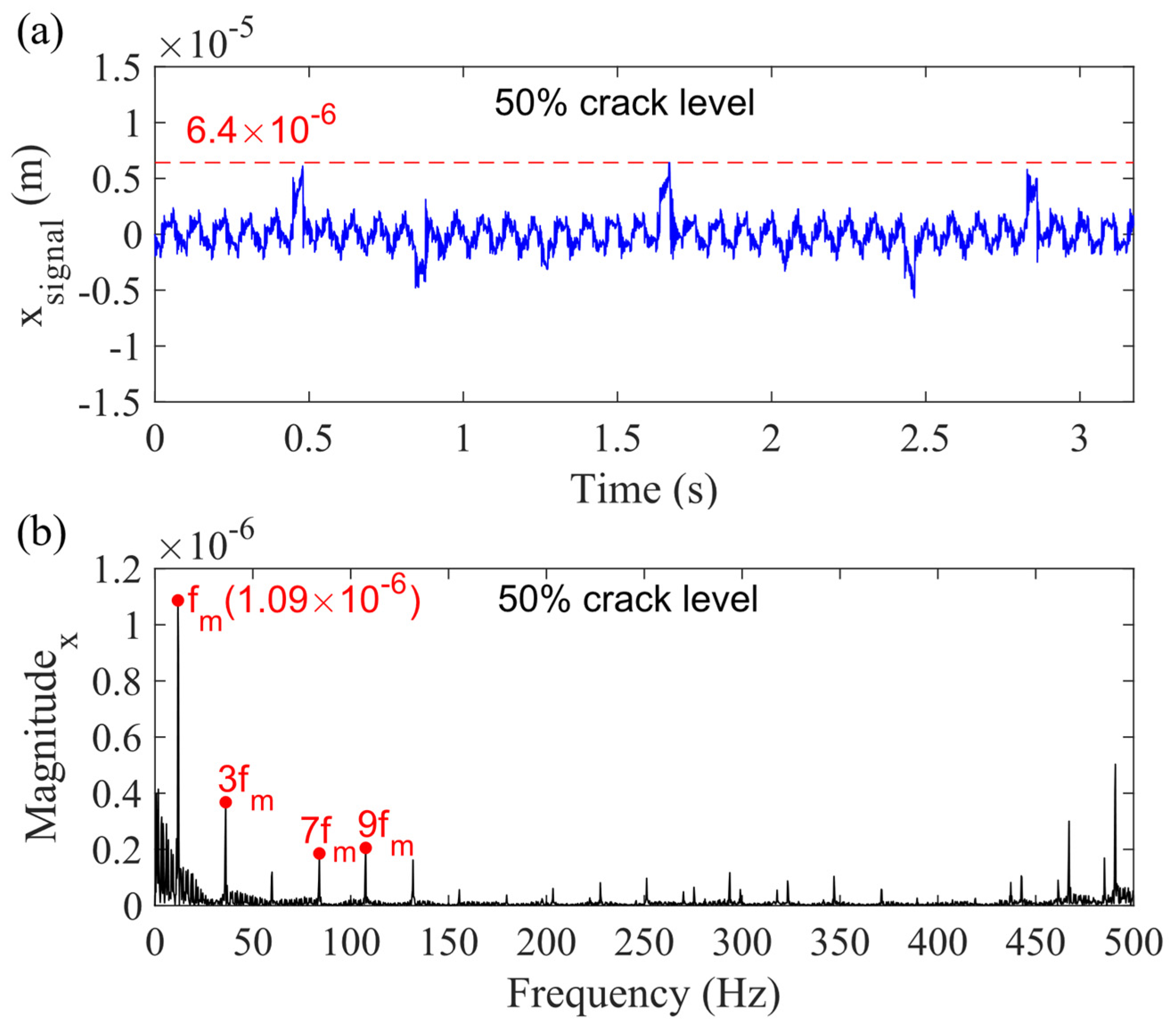
| Case 4 (planet gear bearing clearance) | 2.4 × 10⁻⁶ m | 2.7 × 10⁻⁶ m | 3.0 × 10⁻⁶ m | 3.7 × 10⁻⁶ m | 4.7 × 10−-6 m | 6.4 × 10⁻⁶ m |
| Case 5 (carrier and sun gear bearing clearance) | 1.0 × 10⁻⁶ m | 1.0 × 10⁻⁶ m | 1.2 × 10⁻⁶ m | 1.5 × 10⁻⁶ m | 1.9 × 10⁻⁶ m | 2.8 × 10⁻⁶ m |
| Case 6 (all bearing clearance) | 1.0 × 10⁻⁶ m | 1.1 × 10⁻⁶ m | 1.3 × 10⁻⁶ m | 1.5 × 10⁻⁶ m | 1.9 × 10⁻⁶ m | 2.7 × 10⁻⁶ m |
Publisher’s Note: MDPI stays neutral with regard to jurisdictional claims in published maps and institutional affiliations. |
© 2021 by the authors. Licensee MDPI, Basel, Switzerland. This article is an open access article distributed under the terms and conditions of the Creative Commons Attribution (CC BY) license (https://creativecommons.org/licenses/by/4.0/).
Share and Cite
Chen, X.; Yang, X.; Zuo, M.J.; Tian, Z. Planetary Gearbox Dynamic Modeling Considering Bearing Clearance and Sun Gear Tooth Crack. Sensors 2021, 21, 2638. https://doi.org/10.3390/s21082638
Chen X, Yang X, Zuo MJ, Tian Z. Planetary Gearbox Dynamic Modeling Considering Bearing Clearance and Sun Gear Tooth Crack. Sensors. 2021; 21(8):2638. https://doi.org/10.3390/s21082638
Chicago/Turabian StyleChen, Xianhua, Xingkai Yang, Ming J. Zuo, and Zhigang Tian. 2021. "Planetary Gearbox Dynamic Modeling Considering Bearing Clearance and Sun Gear Tooth Crack" Sensors 21, no. 8: 2638. https://doi.org/10.3390/s21082638
APA StyleChen, X., Yang, X., Zuo, M. J., & Tian, Z. (2021). Planetary Gearbox Dynamic Modeling Considering Bearing Clearance and Sun Gear Tooth Crack. Sensors, 21(8), 2638. https://doi.org/10.3390/s21082638