
Review of Control Techniques in Microinverters


Abstract
:1. Introduction
2. Microinverter
Design Challenges
3. Control Strategies
3.1. Grid Connected
- The paper [30] presents a Flyback PV microinverter with analog and digital controller. The analog control consists of a precision rectifier circuit, a pulse width modulation comparator, and zero-crossing detector. The aim of digital control is to obtain the Maximum Power Point from the Photovoltaic module.
- The paper [31] presents a differential boost microinverter. The control technique consists of a MPPT-loop control, a second loop that synchronizes the grid current to the grid voltage, and a three-loop differential peak current control.
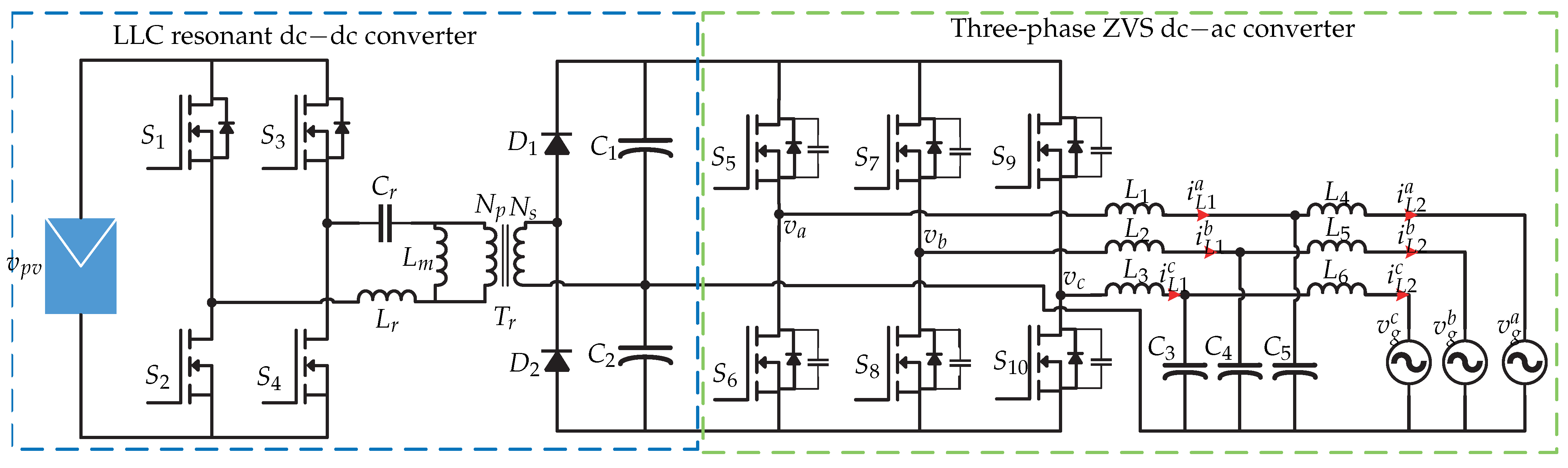
- The paper [32] presents a two stage microinverter with LLC resonant converter. The control technique consists of a MPPT based a fixed-frequency model predictive control and a PI control.
- The paper [33] presents a microinverter based a cascaded boost converter with a full bridge. The control technique consists in two sliding control alternatives (input current mode and pseudo-oscillating mode).
- The paper [34] presents a microinverter based a interleaved flyback with an unfolding H-bridge inverter. The control technique consists in a novel sliding mode control current controller.
- The paper [37] presents a dual-active-bridge (DAB) microinverter. The control strategy consists in simple closed-loop current control (PI controller).
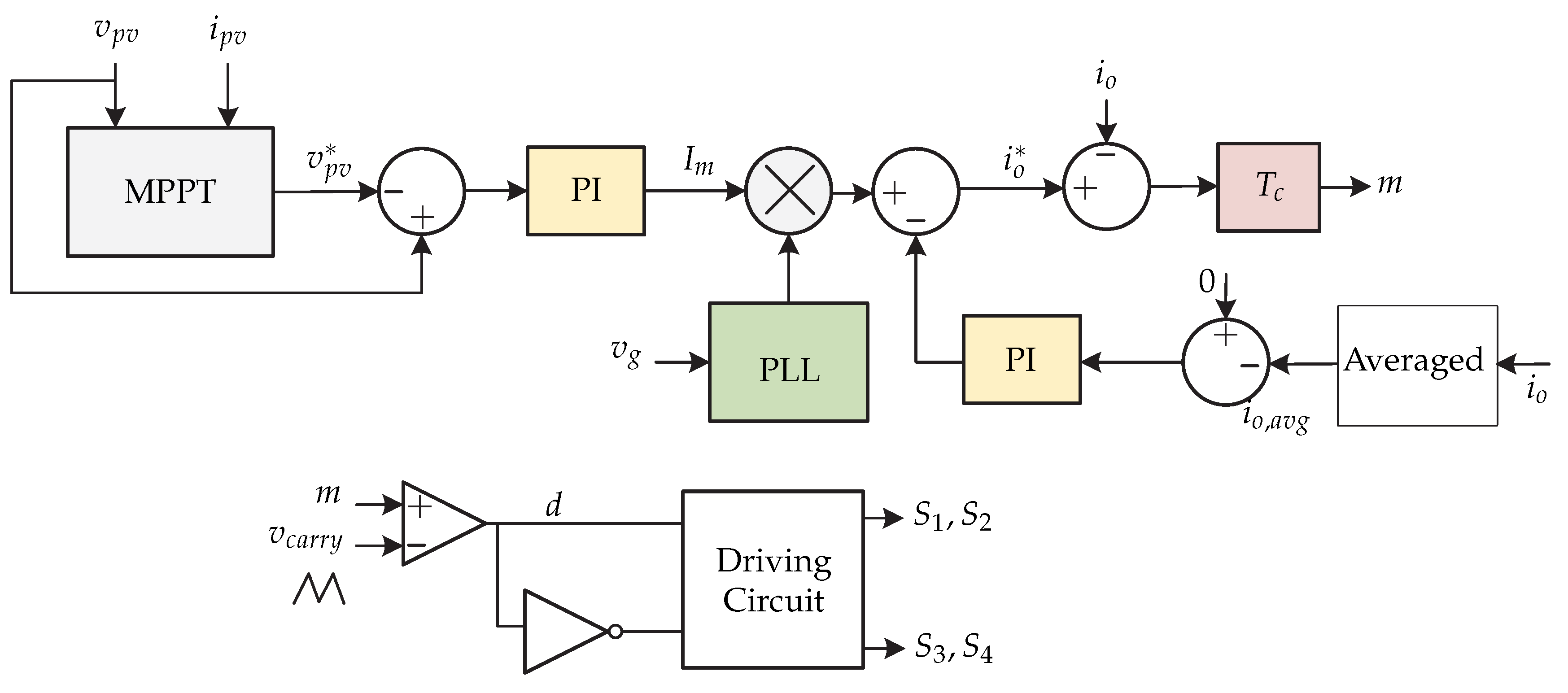
- The paper [38] presents a switched capacitor buck-boost voltage source inverter (SC-BBVSI). The control strategy consists in a PI controller for dc-link voltage regulation and proportional-resonant (PR) controller for injected current regulation.
- The paper [40] presents a two stage microinverter and it consists of boost dc-dc converter with a single-phase full-bridge inverter. The control strategy consists in non-linear control techniques based of the non-linear average model of microinverter.
- The paper [43,44] presents two microinverter topologies. First, a interleaved flyback dc-dc converter with unfolding inverter is presented and then a push–pull dc-dc converter with unfolding inverter. The proposed control strategy consists in a simple PR controller to generate a sinusoidal current reference waveform and PI controller to generate a power reference.
- The paper [45] presents a two-stage microinverter and it consists in a step-up isolation dc-dc converter with half-bridge inverter. The control technique consists in a PI controller in order to reduce the third harmonic. Moreover, it consists in a feedforward control.
- The paper [46] presents a full-bridge inverter for microinverter application. The control technique consists in a sliding mode control of the output current.
- The paper [49] presents a multi-level single phase microinverter and its control strategy consists in a model predictive control to reduce the steady state error of the grid-injected current. Another control technique used in this microinverter is the PI controller with PR controller proposed in [50].
- The paper [51] presents a single stage boost inverter, composed by a two bidirectional boost dc-dc converter. The control strategy consists in a finite control set model predictive control algorithm with predictions of the system variables.
- The paper [52] presents a full-bridge converter cascaded to a boost converter with other full-bridge converter. The control technique consists in a PI controller for dc-link voltage regulation and a PR controller used in the current control loop.
- The paper [53] presents a T-type microinverter in boundary conduction mode. The control technique consists in a hybrid control based on the proposed voltage equalization and adaptive reverse current control method.
- The paper [54] presents a high-gain Z-source boost converter with H-bridge inverter. The control strategy consists of a PI controller to regulate the dc-link voltage and hysteresis current control to regulate the grid current.
- The paper [55] presents a resonant microinverter and its control strategy consists of different PI controllers.
- The paper [56] presents a microinverter based in a modified current source inverter. The control strategy consists in two PI controllers and transformation.
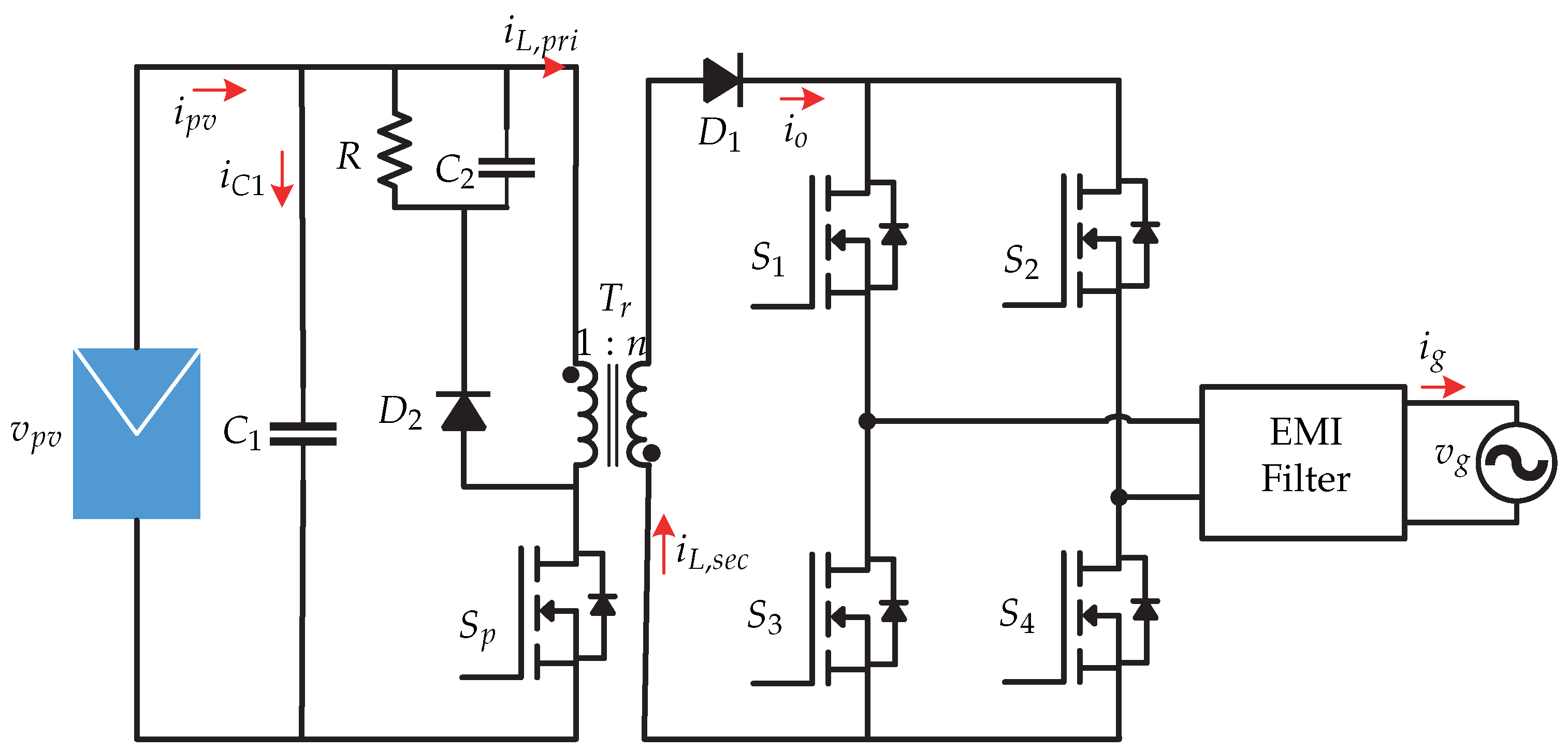
- The paper [57] presents a flyback dc-dc converter with line-frequency inverter. The control strategy consists in a inverse model with a single closed-loop PI controller.
- The paper [58] presents a boost-half-bridge dc-dc converter and full-bridge inverter. The control technique consists in a repetitive current controller based on fourth-order linear phase IIR filter. The repetitive current controller is used to reduce the total harmonic distortion and current regulation. There is a PI controller in the dc-dc stage.
- The paper [59] presents a flyback-based partial power dc-dc converter with a H-bridge inverter. The control strategy consists in a cascaded control loop (PI controllers) for dc-dc stage and a classical single-phase voltage oriented control algorithm for dc-ac stage.
- The paper [60] presents a coupled inductor based cúk dc-dc converter connected to the line frequency current unfolding stage. The control strategy is comprised of different PI controllers.
- The paper [61] presents a LLC dc-dc converter connected to a full-bridge inverter. The control strategy of dc-ac stage consists in a dead-beat scheme. The control strategy of dc-dc stage consists in a simple closed-loop PI control.
3.2. Island Mode
3.3. Reactive Power Compensation
- The paper [67] presents an active clamp flyback converter with a dual-buck inverter. The control consists of a current control (a 2-pole 2-zero compensator) for a dc-dc stage. The control technique in the dc-ac stage consists in a voltage-loop control (PI controller), a current-loop control (3-pole 3-zero compensator and feedback linearization), and a phase-locked loop. The power control is based a transformation.
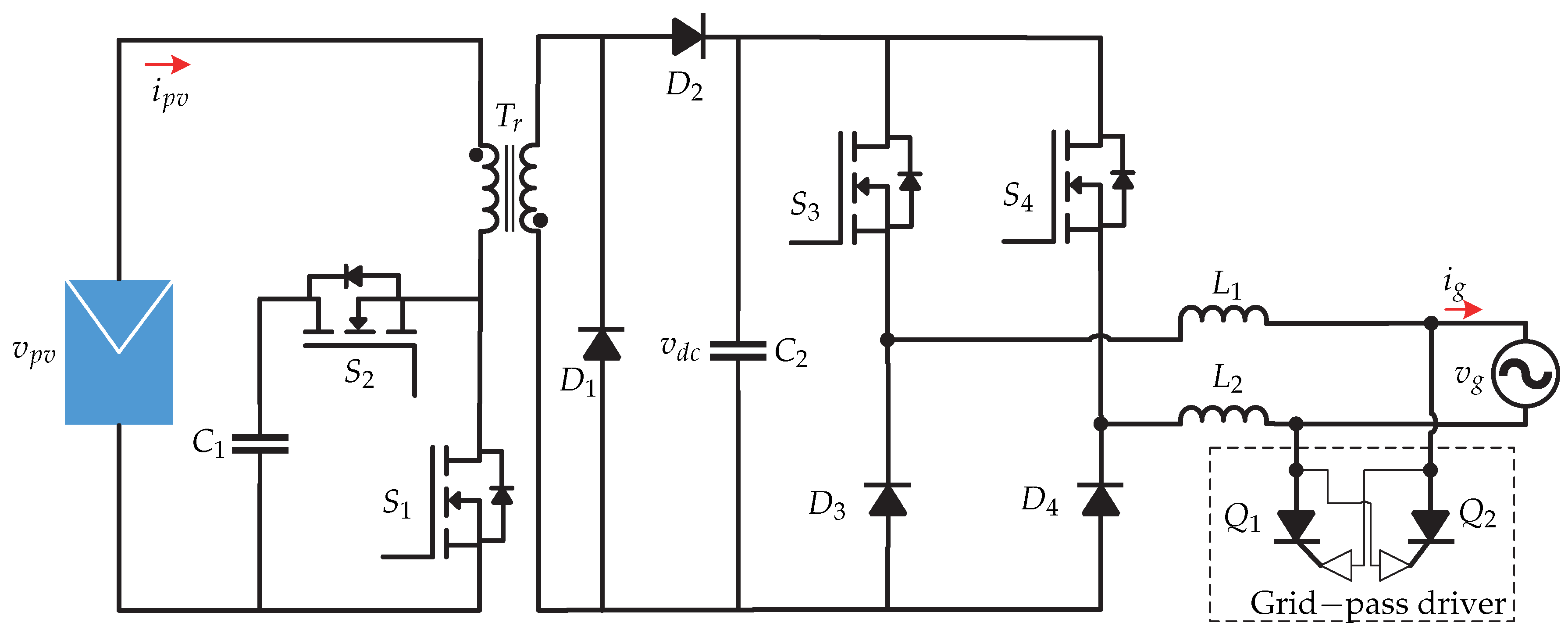
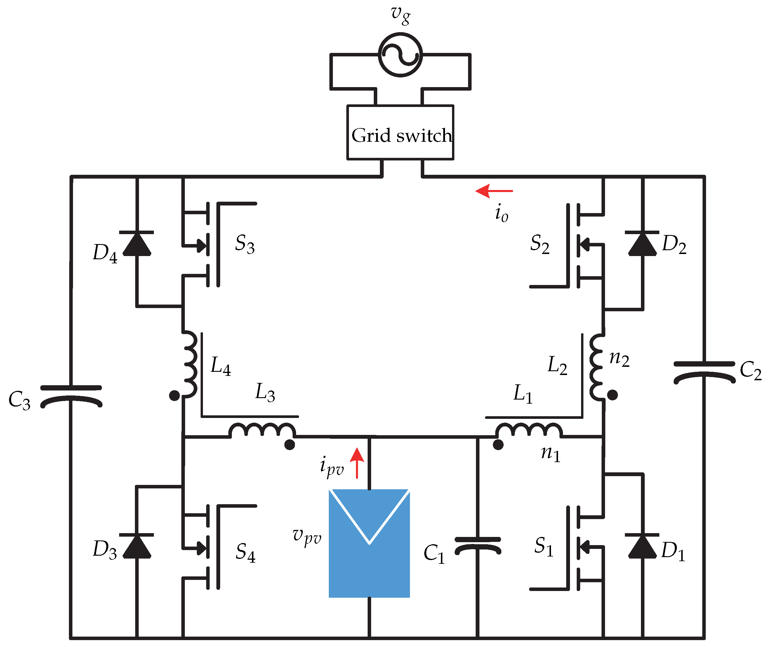
- The paper [68] presents a two-stage microinverter and it consists of a bidirectional boost/buck dc-dc converter with coupled inductors and a full-bridge inverter. The control strategy consists of a conventional current control (PI controller) for reactive power compensation.
- The paper [69] presents a quasi Z-source (qZS) single-phase microinverter. The control strategy consists in a model predictive control with low-voltage ride-through capability.
3.4. Microinverter with Energy Storage
- The paper [71] presents a high-frequency push–pull topology with galvanic isolation with a voltage source inverter. The control technique consists of MPPT controller, a battery charge algorithm (constant current followed by constant voltage control), a dc-link voltage regulator (PI controller), and a current-loop control based a model predictive control.
- The paper [72] presents a dual-active bridge microinverter topology with integrated energy storage capability. The control strategy comprises a cascaded loop with two PI controllers and a two-loop approach with PI controller and PR controller.
3.5. Multi-Modes or Multiples Functions
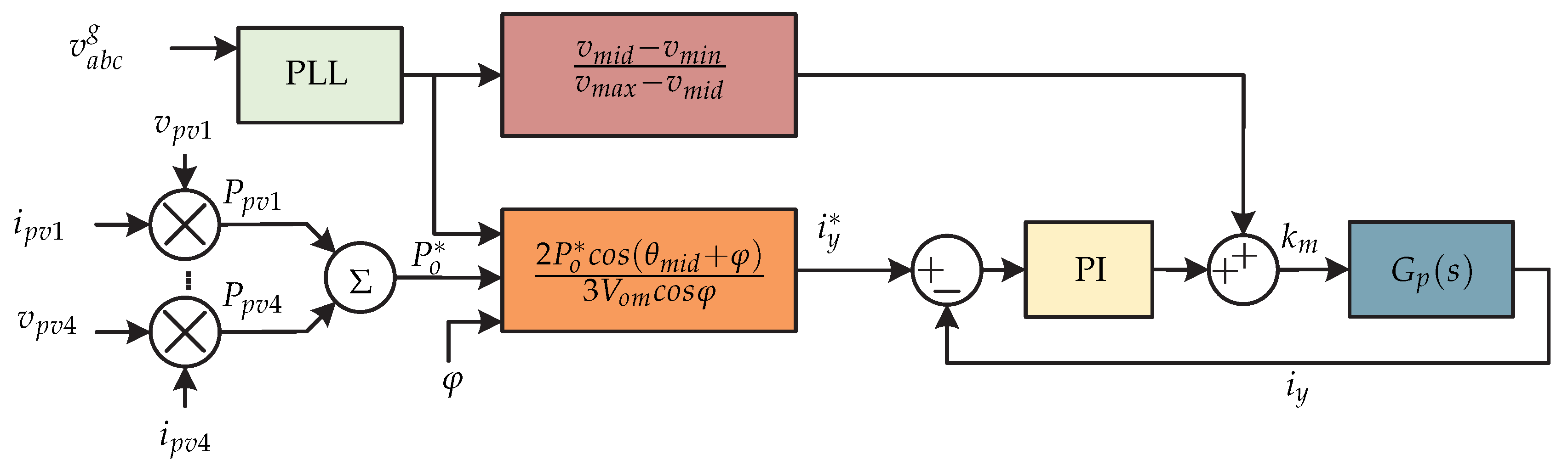
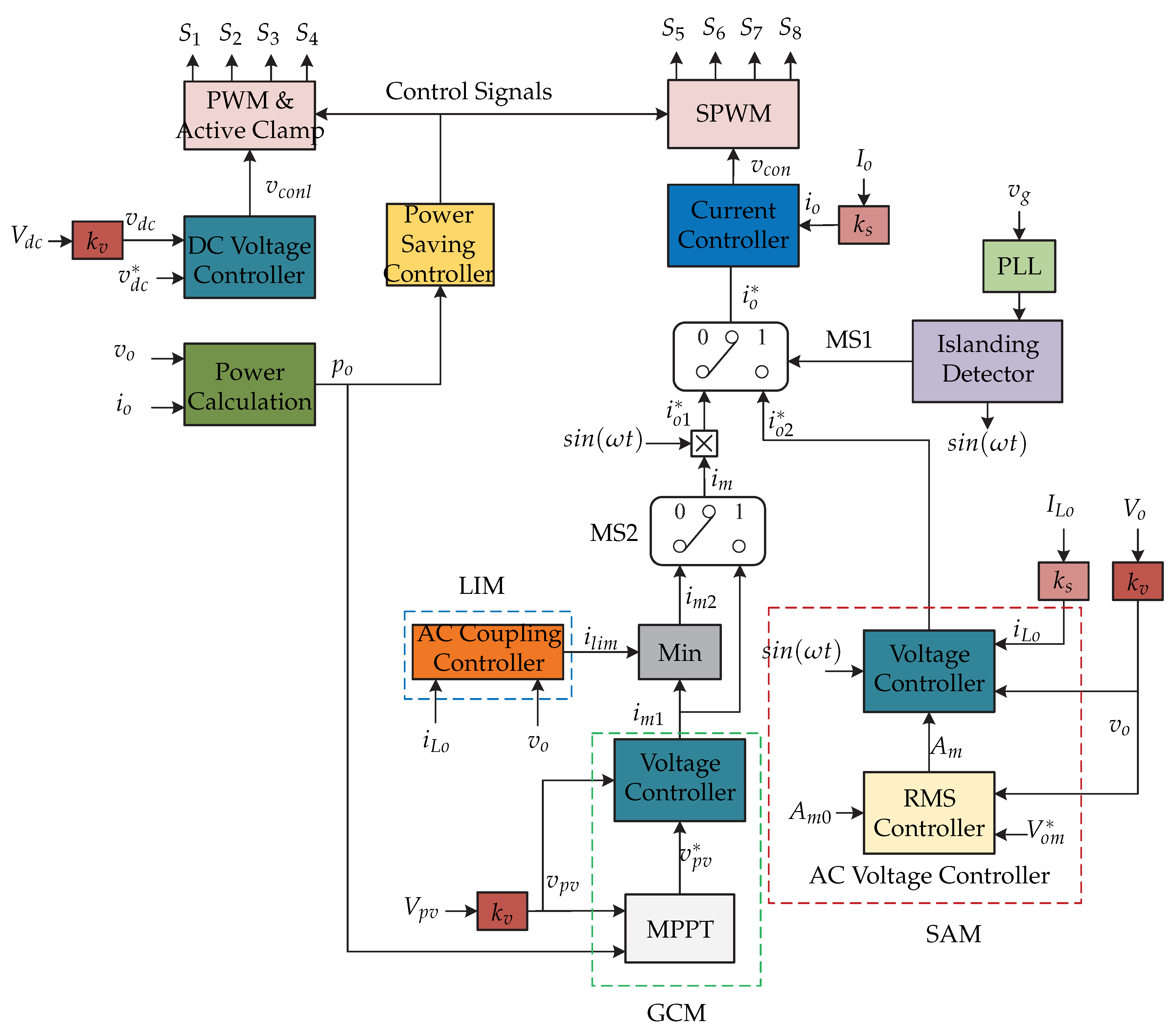
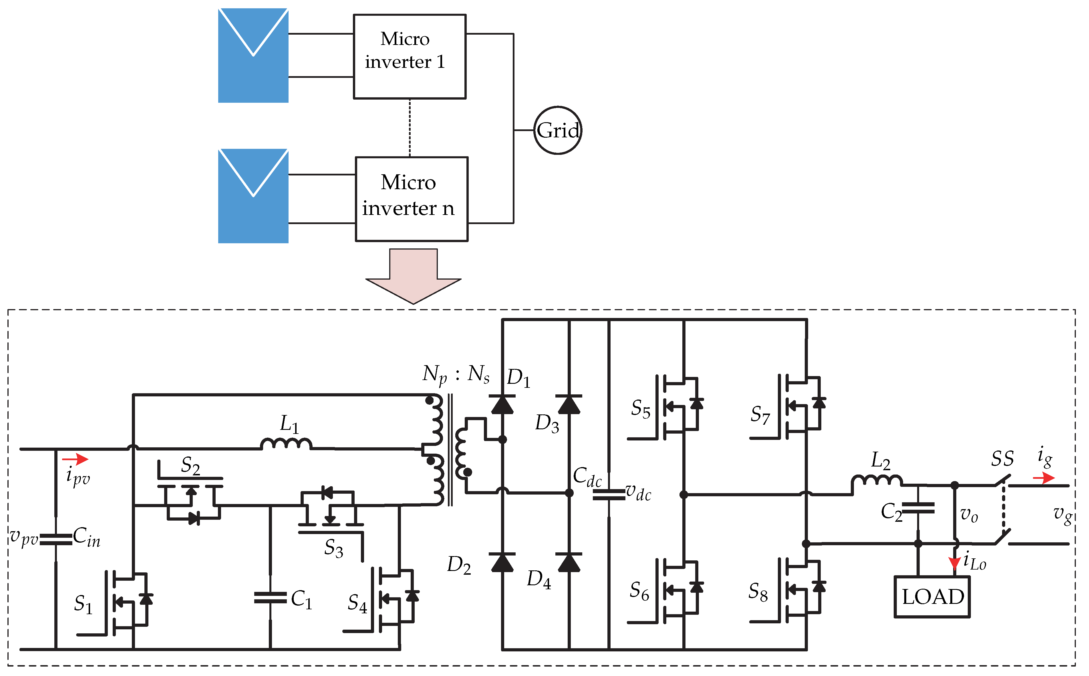
- The paper [77] presents a two-stage microinverter and it consists of dc-dc triple active bridge (TAB) converter that integrates back-up battery; and the second stage is a voltage source inverter (VSI) that operates in both grid-connected mode (GCM) and stand-alone mode (SAM). The control algorithm consists in a central control based in a mode transition scheme. Each mode has PI controllers to regulate the current grid, current load, and dc-link voltage; it has a PR controller to regulate the load voltage.
- The paper [78] presents a buck-boost dc-dc converter cascaded interleaved flyback dc-dc converter with a unfolding bridge inverter. The control technique consists in a droop control and a peak current control.
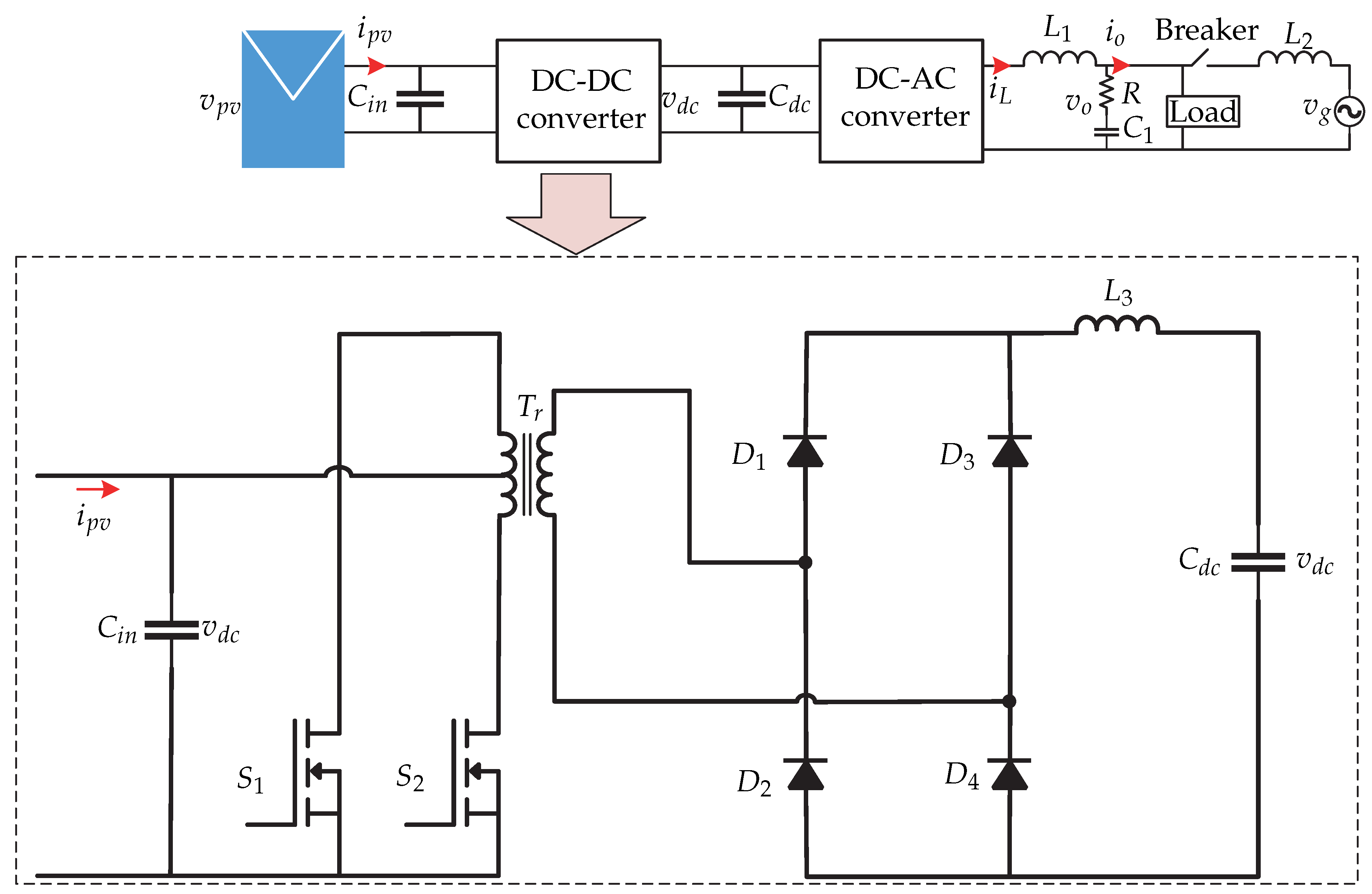
- The paper [79] presents a current-fed push–pull, full-wave rectifier with full-bridge. The microinverter can operate in island mode and grid mode. The control technique comprises of different PI controllers for both modes.
4. Discussion
5. Conclusions
Funding
Institutional Review Board Statement
Informed Consent Statement
Data Availability Statement
Conflicts of Interest
Abbreviations
| ACC | Phase Accumulator |
| DAB | Dual active bridge |
| DMR | Dual Mode Rectifier |
| CVT | Constant Voltage Method |
| EMI | Electromagnetic Interference |
| GCM | Grid Connected Mode |
| GM | Gain Margin |
| HC | Harmonic Compensator |
| LIM | Line-interactive Mode |
| PCM | Peak Current Control |
| PDM | Pulse Density Modulator |
| PM | Phase Margin |
| SAM | Standalone Mode |
| RC | Repetitive Controller |
| THD | Total Harmonic Distortion |
| ZVS | Zero Voltage Switching |
| Voltage amplitude reference | |
| DC-link capacitor | |
| Filter capacitor | |
| Input capacitor | |
| Capacitor | |
| Output capacitor | |
| Resonant capacitor | |
| d | Duty cycle |
| Duty cycle in continuous conduction mode | |
| Duty cycle in discontinuous conduction mode | |
| Diode n, where | |
| Diode n of the microinverter | |
| Rated duty cycle | |
| Hybrid nominal duty ratio | |
| Switching signal pattern | |
| E | Amplitude of the inverter voltage |
| Enable the mode selector | |
| Reference of switching frequency | |
| Sampling frequency | |
| Switching frequency | |
| Transfer function | |
| Battery current | |
| Current of capacitor | |
| d Frame current | |
| Grid current | |
| Amplitude of the grid current reference | |
| Inductor current | |
| Load current | |
| Current of the primary side transformer | |
| Current of the secondary side transformer | |
| Current amplitude limit reference | |
| Photovoltaic panel current | |
| Estimated photovoltaic panel current | |
| Output current | |
| q Frame current | |
| k | Sensor gain |
| Derivative gain | |
| Duty ratio | |
| Proportional gain | |
| Filter inductor | |
| Input inductor | |
| Magnetizing inductor | |
| Inductor n, where | |
| Output inductor n, where | |
| Inductor of transformer | |
| Resonant inductor | |
| m | Amplitude droop coefficient |
| Modulator signal | |
| Overshoot | |
| n | Frequency droop coefficient |
| Output power of the inverter | |
| Power reference | |
| P | Active power |
| Photovoltaic panel power | |
| Q | Reactive power |
| R | Resistor |
| Gating voltages for switches | |
| Switch n, where | |
| Fixed on-time | |
| Settling time | |
| Switching period | |
| Inverter voltage | |
| Battery voltage | |
| Voltage between the terminals | |
| Voltage in the d frame | |
| DC-link voltage | |
| Voltage of capacitor | |
| Grid voltage | |
| Voltage in the maximum power point | |
| Maximum value of the dc-link voltage | |
| Medium value of the dc-link voltage | |
| Minimum value of the dc-link voltage | |
| Limit voltage reference | |
| Output voltage | |
| Magnitude of the output phase voltage. | |
| Voltage in the point common coupling | |
| Photovoltaic panel voltage | |
| Voltage in the q frame | |
| Disturbance or variation | |
| Output angle | |
| Offset signal | |
| Angle of the grid voltage | |
| Frequency of the inverter voltage |
References
- Kouro, S.; Leon, J.I.; Vinnikov, D.; Franquelo, L.G. Grid-Connected Photovoltaic Systems: An Overview of Recent Research and Emerging PV Converter Technology. IEEE Ind. Electron. Mag. 2015, 9, 47–61. [Google Scholar] [CrossRef]
- Masson, G.; Kaizuka, I. Trends in Photovoltaic Applications 2020. International Energy Agency Photovoltaic Power System Report. 2020. Available online: https:iea-pvps.org/wp-content/uploads/2020/11/IEA_PVPS_Trends_Report_2020-1.pdf (accessed on 25 August 2021).
- Yan, Y.; Xiang, L.; Dianfeng, W. Integrated Solutions for Photovoltaic Grid Connection: Increasing the Reliability of Solar Power. IEEE Power Energy Mag. 2014, 12, 84–91. [Google Scholar] [CrossRef]
- Anzalchi, A.; Sundararajan, A.; Moghadasi, A.; Sarwat, A. High-Penetration Grid-Tied Photovoltaics: Analysis of Power Quality and Feeder Voltage Profile. IEEE Ind. Appl. Mag. 2019, 25, 83–94. [Google Scholar] [CrossRef]
- Freddy, T.K.S.; Rahim, N.A. Photovoltaic Inverter Topologies for Grid Integration Applications; Springer: Berlin/Heidelberg, Germany, 2016; pp. 13–42. [Google Scholar]
- Yang, Y.; Kim, K.; Blaabjerg, F.; Sangwongwanich, A. Advances in Grid-Connected Photovoltaic Power Conversion Systems; Woodhead Publishing: Shaxton, UK, 2018. [Google Scholar]
- Ikkurti, H.P.; Saha, S. A comprehensive techno-economic review of microinverters for Building Integrated Photovoltaics (BIPV). Renew. Sustain. Energy Rev. 2015, 47, 997–1006. [Google Scholar] [CrossRef]
- Alluhaybi, K.; Batarseh, I.; Hu, H. Comprehensive Review and Comparison of Single-Phase Grid-Tied Photovoltaic Microinverters. IEEE J. Emerg. Sel. Top. Power Electron. 2020, 8, 1310–1329. [Google Scholar] [CrossRef]
- Xiao, W.; Moursi, M.; Khan, O.; Infield, D. A Review of Grid-Tied Converter Topologies Used in Photovoltaic Systems. Renew. Power Gener. IET 2016, 10, 1543–1551. [Google Scholar] [CrossRef] [Green Version]
- Sher, H.A.; Addoweesh, K.E. Micro-inverters—Promising solutions in solar photovoltaics. Energy Sustain. Dev. 2012, 16, 389–400. [Google Scholar] [CrossRef]
- Garcia-Rodriguez, L.; Jones, V.; Balda, J.; Lindstrom, E.; Oliva, A.; Gonzalez-Llorente, J. Design of a GaN-based microinverter for photovoltaic systems. In Proceedings of the 2014 IEEE 5th International Symposium on Power Electronics for Distributed Generation Systems (PEDG), Galway, Ireland, 24–27 June 2014; pp. 1–6. [Google Scholar] [CrossRef]
- Zhang, H.; Li, X.; Xiao, S.; Balog, R.S. Hybrid hysteresis current control and low-frequency current harmonics mitigation based on proportional resonant in dc/ac inverter. IET Power Electron. 2018, 11, 2093–2101. [Google Scholar] [CrossRef]
- Jiang, S.; Cao, D.; Li, Y.; Peng, F.Z. Grid-Connected Boost-Half-Bridge Photovoltaic Microinverter System Using Repetitive Current Control and Maximum Power Point Tracking. IEEE Trans. Power Electron. 2012, 27, 4711–4722. [Google Scholar] [CrossRef]
- Jiang, S.; Cao, D.; Peng, F.Z.; Li, Y. Grid-connected boost-half-bridge photovoltaic micro inverter system using repetitive current control and maximum power point tracking. In Proceedings of the 2012 Twenty-Seventh Annual IEEE Applied Power Electronics Conference and Exposition (APEC), Orlando, FL, USA, 5–9 February 2012; pp. 590–597. [Google Scholar] [CrossRef]
- Chen, L.; Hu, C.; Zhang, Q.; Zhang, K.; Batarseh, I. Modeling and Triple-Loop Control of ZVS Grid-Connected DC/AC Converters for Three-Phase Balanced Microinverter Application. IEEE Trans. Power Electron. 2015, 30, 2010–2023. [Google Scholar] [CrossRef]
- Chen, L.; Amirahmadi, A.; Zhang, Q.; Kutkut, N.; Batarseh, I. Design and Implementation of Three-Phase Two-Stage Grid-Connected Module Integrated Converter. IEEE Trans. Power Electron. 2014, 29, 3881–3892. [Google Scholar] [CrossRef]
- Chen, F.; Zhang, Q.; Amirahmadi, A.; Batarseh, I. Modeling and analysis of DC-link voltage for three-phase four-wire two-stage micro-inverter. In Proceedings of the 2014 IEEE Applied Power Electronics Conference and Exposition-APEC 2014, Fort Worth, TX, USA, 16–20 March 2014; pp. 3000–3005. [Google Scholar] [CrossRef]
- Rajeev, M.; Agarwal, V. Analysis and Control of a Novel Transformer-Less Microinverter for PV-Grid Interface. IEEE J. Photovoltaics 2018, 8, 1110–1118. [Google Scholar] [CrossRef]
- Falconar, N.; Beyragh, D.S.; Pahlevani, M. An Adaptive Sensorless Control Technique for a Flyback-Type Solar Tile Microinverter. IEEE Trans. Power Electron. 2020, 35, 13554–13562. [Google Scholar] [CrossRef]
- Falconar, N.; Beyragh, D.S.; Pahlevani, M. A novel control system for solar tile micro-inverters. In Proceedings of the 2018 IEEE Applied Power Electronics Conference and Exposition (APEC), San Antonio, TX, USA, 4–8 March 2018; pp. 375–380. [Google Scholar] [CrossRef]
- Öztürk, S.; Çadırcı, I. A Generalized and Flexible Control Scheme for Photovoltaic Grid-Tie Microinverters. IEEE Trans. Ind. Appl. 2018, 54, 505–516. [Google Scholar] [CrossRef]
- Öztürk, S.; Çaditoi, I. A generalized and flexible control scheme for photovoltaic grid-tie microinverters. In Proceedings of the 2015 International Conference on Renewable Energy Research and Applications (ICRERA), Palermo, Italy, 22–25 November 2015; pp. 699–703. [Google Scholar] [CrossRef]
- Öztürk, S.; Çadirci, I. A generalized control approach for photovoltaic grid-tie microinverters. In Proceedings of the 2015 Intl Aegean Conference on Electrical Machines Power Electronics (ACEMP), 2015 Intl Conference on Optimization of Electrical Electronic Equipment (OPTIM) 2015 Intl Symposium on Advanced Electromechanical Motion Systems (ELECTROMOTION), Side, Turkey, 2–4 September 2015; pp. 800–806. [Google Scholar] [CrossRef]
- Öztürk, S.; Çadirci, I. DSPIC microcontroller based implementation of a flyback PV microinverter using Direct Digital Synthesis. In Proceedings of the 2013 IEEE Energy Conversion Congress and Exposition, Denver, CO, USA, 15–19 September 2013; pp. 3426–3433. [Google Scholar] [CrossRef]
- Cha, W.; Cho, Y.; Kwon, J.; Kwon, B. Highly Efficient Microinverter With Soft-Switching Step-Up Converter and Single-Switch-Modulation Inverter. IEEE Trans. Ind. Electron. 2015, 62, 3516–3523. [Google Scholar] [CrossRef]
- Fang, Y.; Ma, X. A Novel PV Microinverter With Coupled Inductors and Double-Boost Topology. IEEE Trans. Power Electron. 2010, 25, 3139–3147. [Google Scholar] [CrossRef]
- Shen, Y.; Wang, H.; Shen, Z.; Yang, Y.; Blaabjerg, F. A 1-MHz Series Resonant DC–DC Converter With a Dual-Mode Rectifier for PV Microinverters. IEEE Trans. Power Electron. 2019, 34, 6544–6564. [Google Scholar] [CrossRef] [Green Version]
- Shen, Y.; Wang, H.; Shen, Z.; Yang, Y.; Blaabjerg, F. Series Resonant DC-DC Converter With Dual-Mode Rectifier for PV Microinverters. In Proceedings of the 2018 International Power Electronics Conference (IPEC-Niigata 2018-ECCE Asia), Niigata, Japan, 20–24 May 2018; pp. 1788–1792. [Google Scholar] [CrossRef]
- Lee, S.; Cha, W.; Kwon, J.; Kwon, B. Control Strategy of Flyback Microinverter With Hybrid Mode for PV AC Modules. IEEE Trans. Ind. Electron. 2016, 63, 995–1002. [Google Scholar] [CrossRef]
- Yaqoob, S.J.; Obed, A.; Zubo, R.; Al-Yasir, Y.I.A.; Fadhel, H.; Mokryani, G.; Abd-Alhameed, R.A. Flyback Photovoltaic Micro-Inverter with a Low Cost and Simple Digital-Analog Control Scheme. Energies 2021, 14, 4239. [Google Scholar] [CrossRef]
- El Aroudi, A.; Debbat, M.; Al-Numay, M.; Abouloiafa, A. Fast-Scale Instability and Stabilization by Adaptive Slope Compensation of a PV-Fed Differential Boost Inverter. Appl. Sci. 2021, 11, 2106. [Google Scholar] [CrossRef]
- Abdel-Rahim, O.; Alamir, N.; Abdelrahem, M.; Orabi, M.; Kennel, R.; Ismeil, M.A. A Phase-Shift-Modulated LLC-Resonant Micro-Inverter Based on Fixed Frequency Predictive-MPPT. Energies 2020, 13, 1460. [Google Scholar] [CrossRef] [Green Version]
- Valderrama-Blavi, H.; Rodríguez-Ramos, E.; Olalla, C.; Genaro-Muñoz, X. Sliding-Mode Approaches to Control a Microinverter Based on a Quadratic Boost Converter. Energies 2019, 12, 3697. [Google Scholar] [CrossRef] [Green Version]
- Dong, M.; Tian, X.; Li, L.; Song, D.; Wang, L.; Zhao, M. Model-Based Current Sharing Approach for DCM Interleaved Flyback Micro-Inverter. Energies 2018, 11, 1685. [Google Scholar] [CrossRef] [Green Version]
- Hsieh, H.I.; Hou, J. Realization of Interleaved PV Microinverter by Quadrature-Phase-Shift SPWM Control. IEEJ J. Ind. Appl. 2015, 4, 643–649. [Google Scholar] [CrossRef]
- Hsieh, H.I.; Hsieh, G.C.; Hou, J. Realization study of interleaved PV microinverter by quadrature-phase-shift SPWM control. In Proceedings of the 2014 International Power Electronics Conference (IPEC-Hiroshima 2014-ECCE ASIA), Hiroshima, Japan, 18–21 May 2014; pp. 526–531. [Google Scholar] [CrossRef]
- Kim, K.S.; Jeong, S.G.; Kwon, B.H. Single power-conversion DAB microinverter with safe commutation and high efficiency for PV power applications. Sol. Energy 2019, 193, 676–683. [Google Scholar] [CrossRef]
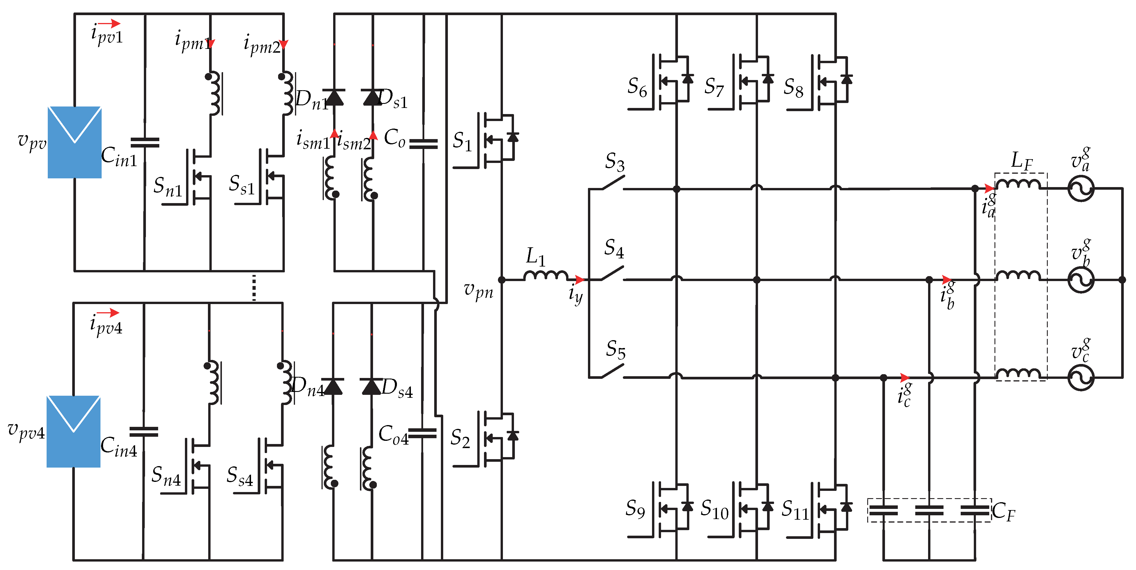
- Gaafar, M.A.; Ibrahim, E.A.; Orabi, M. Multi-input transformer-less four-wire microinverter with distributed MPPT for PV systems. Int. J. Circuit Theory Appl. 2021, 49, 1704–1725. [Google Scholar] [CrossRef]
- Evran, F. Design and control of an LCL-type single-phase grid-connected inverter with inverter current feedback using the phase-delay method. Turk. J. Electr. Eng. Comput. Sci. 2019, 27, 4702–4714. [Google Scholar] [CrossRef]
- Yahya, A.; El Fadil, H.; Oulcaid, M.; Ammeh, L.; Giri, F.; Guerrero, J.M. Control of Grid Connected Photovoltaic Systems with Microinverters: New Theoretical Design and Numerical Evaluation. Asian J. Control. 2018, 20, 906–918. [Google Scholar] [CrossRef]
- Renaudineau, H.; Lopez, D.; Flores-Bahamonde, F.; Kouro, S. Flatness-based control of a boost inverter for PV microinverter application. In Proceedings of the 2017 IEEE 8th International Symposium on Power Electronics for Distributed Generation Systems (PEDG), Florianopolis, Brazil, 17–20 April 2017; pp. 1–6. [Google Scholar] [CrossRef]
- Lopez, D.; Flores-Bahamonde, F.; Renaudineau, H.; Kouro, S. Double voltage step-up photovoltaic microinverter. In Proceedings of the 2017 IEEE International Conference on Industrial Technology (ICIT), Toronto, ON, Canada, 22–25 March 2017; pp. 406–411. [Google Scholar] [CrossRef]
- Caiza, D.L.; Kouro, S.; Flores-Bahamonde, F.; Hernandez, R. Unfolding PV Microinverter Current Control: Rectified Sinusoidal vs Sinusoidal Reference Waveform. In Proceedings of the 2018 IEEE Energy Conversion Congress and Exposition (ECCE), Portland, OR, USA, 23–27 September 2018; pp. 7094–7100. [Google Scholar] [CrossRef]
- Lopez, D.; Renaudineau, H.; Flores-Bahamonde, F.; Kouro, S. Evaluation of photovoltaic microinverter configurations based on different converter stages and step-up voltage ratios. In Proceedings of the 2017 19th European Conference on Power Electronics and Applications (EPE’17 ECCE Europe), Warsaw, Poland, 11–14 September 2017; pp. P.1–P.8. [Google Scholar] [CrossRef]
- Vongkoon, P.; Liutanakul, P.; Wiwatcharagoses, N. Analysis and Design of DC Bus Voltage Control Regarding Third Harmonic Reduction and Dynamic Improvement for Half-Bridge Microinverter. In Proceedings of the 2018 15th International Conference on Electrical Engineering/Electronics, Computer, Telecommunications and Information Technology (ECTI-CON), Chiang Rai, Thailand, 18–21 July 2018; pp. 17–20. [Google Scholar] [CrossRef]
- Lopez-Santos, O.; Garcia, G.; Martinez-Salamero, L.; Cortes-Torres, L. Suppressing the effect of the DC-link voltage ripple on the current control of a sliding-mode controlled microinverter. In Proceedings of the 2015 CHILEAN Conference on Electrical, Electronics Engineering, Information and Communication Technologies (CHILECON), Santiago, Chile, 28–30 October 2015; pp. 447–452. [Google Scholar] [CrossRef]
- Lopez-Santos, O.; García, G.; Martinez-Salamero, L. Derivation of a global model of a two-stage photovoltaic microinverter using sliding-mode control. In Proceedings of the 2015 IEEE 13th Brazilian Power Electronics Conference and 1st Southern Power Electronics Conference (COBEP/SPEC), Fortaleza, Brazil, 29 November–2 December 2015; pp. 1–6. [Google Scholar] [CrossRef]
- Sahu, P.K.; Shaw, P.; Maity, S. Modeling and control of grid-connected DC/AC converters for single-phase micro-inverter application. In Proceedings of the 2015 Annual IEEE India Conference (INDICON), New Delhi, India, 17–20 December 2015; pp. 1–6. [Google Scholar] [CrossRef]
- Abdeen, E.; Gaafar, M.A.; Orabi, M.; Wang, F. Predictive Control of Multi-Level Single Phase Microinverter. In Proceedings of the 2019 IEEE International Symposium on Predictive Control of Electrical Drives and Power Electronics (PRECEDE), Quanzhou, China, 31 May–2 June 2019; pp. 1–5. [Google Scholar] [CrossRef]
- Abdeen, E.; Gaafar, M.A.; Orabi, M.; Youssef, M. A Novel High Gain Single-phase Transformer-less Multi-level Micro-inverter. In Proceedings of the 2019 IEEE Applied Power Electronics Conference and Exposition (APEC), Anaheim, CA, USA, 17–21 March 2019; pp. 3263–3268. [Google Scholar] [CrossRef]
- Lopez, D.; Flores-Bahamonde, F.; Kouro, S.; Perez, M.A.; Llor, A.; Martínez-Salamero, L. Predictive control of a single-stage boost DC-AC photovoltaic microinverter. In Proceedings of the IECON 2016–42nd Annual Conference of the IEEE Industrial Electronics Society, Florence, Italy, 23–26 October 2016; pp. 6746–6751. [Google Scholar] [CrossRef]
- Bahraini, F.; Abrishamifar, A.; Rahmati, A. A Single-Phase Grid-Connected PV Microinverter With Very Low DC Bus Capacitance, Low THD, and Improved Transient Response. In Proceedings of the 2019 10th International Power Electronics, Drive Systems and Technologies Conference (PEDSTC), Shiraz, Iran, 12–14 February 2019; pp. 481–486. [Google Scholar] [CrossRef]
- Wan, C.; Li, L.; Wang, C. Adaptive reverse current control and voltage equalization strategy for T-type BCM Microinverter. In Proceedings of the IECON 2020 The 46th Annual Conference of the IEEE Industrial Electronics Society, Singapore, 18–21 October 2020; pp. 1217–1222. [Google Scholar] [CrossRef]
- Prabhu, N.S.; Viswadev, R.; Venkatesaperumal, B.; Mishra, S. A Transformerless Photovoltaic Microinverter using High-gain Z-Source Boost Converter for Single-phase Grid connected Applications. In Proceedings of the 2020 IEEE International Conference on Power Electronics, Smart Grid and Renewable Energy (PESGRE2020), Cochin, India, 2–4 January 2020; pp. 1–6. [Google Scholar] [CrossRef]
- Zhao, X.; Zhang, L.; Ma, Q.; Lai, J.S. Modeling and control of a wide-input hybrid resonant microconverter for photovoltaic applications. In Proceedings of the 2016 Asian Conference on Energy, Power and Transportation Electrification (ACEPT), Singapore, 25–27 October 2016; pp. 1–6. [Google Scholar] [CrossRef]
- Lorenzani, E.; Immovilli, F.; Bianchini, C.; Bellini, A. Performance analysis of a modified Current Source Inverter for photovoltaic microinverter applications. In Proceedings of the IECON 2013–39th Annual Conference of the IEEE Industrial Electronics Society, Vienna, Austria, 10–13 November 2013; pp. 1809–1814. [Google Scholar] [CrossRef]
- Liu, W.; Yang, L.; Chen, W.; Wang, Y.; Wang, D.; Li, S. Grid current control of flyback type Micro Inverter based on FASVM. In Proceedings of the 2016 35th Chinese Control Conference (CCC), Chengdu, China, 27–29 July 2016; pp. 8716–8720. [Google Scholar] [CrossRef]
- Dhivya, R.; Jaiganesh, K.; Duraiswamy, K. Performance analysis of boost half bridge photovoltaic microinverter using RCC variable step size algorithm. In Proceedings of the 2013 International Conference on Renewable Energy and Sustainable Energy (ICRESE), Coimbatore, India, 5–6 December 2013; pp. 75–80. [Google Scholar] [CrossRef]
- Zapata, J.W.; Renaudineau, H.; Kouro, S.; Perez, M.A.; Meynard, T.A. Partial power DC-DC converter for photovoltaic microinverters. In Proceedings of the IECON 2016–42nd Annual Conference of the IEEE Industrial Electronics Society, Florence, Italy, 23–26 October 2016; pp. 6740–6745. [Google Scholar] [CrossRef]
- Bhattacharya, A.; Paul, A.R.; Chatterjee, K. A Coupled Inductor Based Ćuk Microinverter for Grid Connected Photovoltaic Applications. In Proceedings of the 2020 IEEE International Conference on Power Electronics, Drives and Energy Systems (PEDES), Jaipur, India, 16–19 December 2020; pp. 1–6. [Google Scholar] [CrossRef]
- Xingkui, M.; Qisheng, H.; Qingbo, K.; Yudi, X.; Zhe, Z.; Andersen, M.A.E. Grid-connected photovoltaic micro-inverter with new hybrid control LLC resonant converter. In Proceedings of the IECON 2016–42nd Annual Conference of the IEEE Industrial Electronics Society, Florence, Italy, 23–26 October 2016; pp. 2319–2324. [Google Scholar] [CrossRef] [Green Version]
- Chakraborty, S.; Chattopadhyay, S. A Dual-Active-Bridge-Based Fully ZVS HF-Isolated Inverter With Low Decoupling Capacitance. IEEE Trans. Power Electron. 2020, 35, 2615–2628. [Google Scholar] [CrossRef]
- Korosec, L.; Konjedic, T.; Truntic, M.; Rodic, M.; Milanovic, M. Field programmable gate array-based control method for a pulse density modulated microinverter operating in island mode. IET Power Electron. 2016, 9, 2621–2630. [Google Scholar] [CrossRef]
- Dong, D.; Agamy, M.S.; Harfman-Todorovic, M.; Liu, X.; Garces, L.; Zhou, R.; Cioffi, P. A PV Residential Microinverter With Grid-Support Function: Design, Implementation, and Field Testing. IEEE Trans. Ind. Appl. 2018, 54, 469–481. [Google Scholar] [CrossRef]
- Zhang, L.; Sun, K.; Li, Y.W.; Lu, X.; Zhao, J. A Distributed Power Control of Series-Connected Module-Integrated Inverters for PV Grid-Tied Applications. IEEE Trans. Power Electron. 2018, 33, 7698–7707. [Google Scholar] [CrossRef]
- Feng, J.; Wang, H.; Xu, J.; Su, M.; Gui, W.; Li, X. A Three-Phase Grid-Connected Microinverter for AC Photovoltaic Module Applications. IEEE Trans. Power Electron. 2018, 33, 7721–7732. [Google Scholar] [CrossRef]
- Burbano-Benavides, D.S.; Ortiz-Sotelo, O.D.; Revelo-Fuelagán, J.; Candelo-Becerra, J.E. Design of an On-Grid Microinverter Control Technique for Managing Active and Reactive Power in a Microgrid. Appl. Sci. 2021, 11, 4765. [Google Scholar] [CrossRef]
- Min, G.H.; Lee, K.H.; Ha, J.I.; Kim, M.H. Design and Control of Single-Phase Grid-Connected Photovoltaic Microinverter with Reactive Power Support Capability. In Proceedings of the 2018 International Power Electronics Conference (IPEC-Niigata 2018-ECCE Asia), Niigata, Japan, 20–24 May 2018; pp. 2500–2504. [Google Scholar] [CrossRef]
- Jain, S.; Easley, M.; Shadmand, M.B.; Mirafzal, B. Decoupled active and reactive power predictive control of impedance source microinverter with LVRT capability. In Proceedings of the 2018 IEEE Power and Energy Conference at Illinois (PECI), Champaign, IL, USA, 22–23 February 2018; pp. 1–6. [Google Scholar] [CrossRef]
- Poshtkouhi, S.; Trescases, O. Flyback Mode for Improved Low-Power Efficiency in the Dual-Active-Bridge Converter for Bidirectional PV Microinverters With Integrated Storage. IEEE Trans. Ind. Appl. 2015, 51, 3316–3324. [Google Scholar] [CrossRef]
- Barros, L.A.M.; Tanta, M.; Sousa, T.J.C.; Afonso, J.L.; Pinto, J.G. New Multifunctional Isolated Microinverter with Integrated Energy Storage System for PV Applications. Energies 2020, 13, 4016. [Google Scholar] [CrossRef]
- Chakraborty, S.; Chattopadhyay, S. A multi-port, isolated PV microinverter with low decoupling capacitance amp; integrated battery charger. In Proceedings of the 2016 IEEE Energy Conversion Congress and Exposition (ECCE), Milwaukee, WI, USA, 18–22 September 2016; pp. 1–8. [Google Scholar] [CrossRef]
- Chiang, H.; Lin, F.; Chang, J. Novel Control Method for Multimodule PV Microinverter With Multiple Functions. IEEE Trans. Power Electron. 2018, 33, 5869–5879. [Google Scholar] [CrossRef]
- Trujillo Rodriguez, C.; Velasco de la Fuente, D.; Garcera, G.; Figueres, E.; Guacaneme Moreno, J.A. Reconfigurable Control Scheme for a PV Microinverter Working in Both Grid-Connected and Island Modes. IEEE Trans. Ind. Electron. 2013, 60, 1582–1595. [Google Scholar] [CrossRef] [Green Version]
- Trujillo, C.L.; Velasco, D.; Figueres, E.; Garcera, G.; Ortega, R. Modeling and control of a push-pull converter for photovoltaic microinverters operating in island mode. Appl. Energy 2011, 88, 2824–2834. [Google Scholar] [CrossRef] [Green Version]
- Trujillo, C.L.; Velasco, D.; Garcerá, G.; Figueres, E.; Ortega, R. Reconfigurable control scheme for a microinverter working in both grid connected and island mode. In Proceedings of the 2011 IEEE International Symposium on Industrial Electronics, Gdansk, Poland, 27–30 June 2011; pp. 1477–1481. [Google Scholar] [CrossRef]
- Vera, F.A.M.; Prado, J.D.P.; Moriano, J.J.S.; Zuñiga, C.G.P.; Sal y Rosas Celi, D.E. Bidirectional multiport microinverter and grid-multimode-operation control for a non-linear load. In Proceedings of the 2017 IEEE Workshop on Power Electronics and Power Quality Applications (PEPQA), Bogota, Colombia, 31 May–2 June 2017; pp. 1–6. [Google Scholar] [CrossRef]
- Ji, F.; Mu, L.; Zhu, G. A novel Multi-functional photovoltaic Micro-inverter and its control strategy. In Proceedings of the 2016 IEEE 8th International Power Electronics and Motion Control Conference (IPEMC-ECCE Asia), Hefei, China, 22–26 May 2016; pp. 1302–1305. [Google Scholar] [CrossRef]
- Felgemacher, C.; Jaeger, P.; Kobeissi, A.; Pfeiffer, J.; Wiegand, D.; Kruschel, W.; Dombert, B.; Vasconcelos Araujo, S.; Zacharias, P. Design of Photovoltaic Microinverter for Off-Grid and Grid-Parallel Applications. In Proceedings of the CIPS 2014 8th International Conference on Integrated Power Electronics Systems, Nuremberg, Germany, 25–27 February 2014; pp. 1–6. [Google Scholar]
- Zhang, Y.; Yin, Z.; Li, W.; Liu, J.; Zhang, Y. Adaptive Sliding-Mode-Based Speed Control in Finite Control Set Model Predictive Torque Control for Induction Motors. IEEE Trans. Power Electron. 2021, 36, 8076–8087. [Google Scholar] [CrossRef]
- Parvez, M.; Elias, M.F.M.; Rahim, N.A.; Blaabjerg, F.; Abbott, D.; Al-Sarawi, S.F. Comparative Study of Discrete PI and PR Controls for Single-Phase UPS Inverter. IEEE Access 2020, 8, 45584–45595. [Google Scholar] [CrossRef]
- Kouro, S.; Perez, M.A.; Rodriguez, J.; Llor, A.M.; Young, H.A. Model Predictive Control: MPC’s Role in the Evolution of Power Electronics. IEEE Ind. Electron. Mag. 2015, 9, 8–21. [Google Scholar] [CrossRef]
- Khazaei, J.; Tu, Z.; Asrari, A.; Liu, W. Feedback Linearization Control of Converters With LCL Filter for Weak AC Grid Integration. IEEE Trans. Power Syst. 2021, 36, 3740–3750. [Google Scholar] [CrossRef]
- Hannan, M.A.; Ghani, Z.A.; Hoque, M.M.; Ker, P.J.; Hussain, A.; Mohamed, A. Fuzzy Logic Inverter Controller in Photovoltaic Applications: Issues and Recommendations. IEEE Access 2019, 7, 24934–24955. [Google Scholar] [CrossRef]


| Cite | GM (dB) | PM | THD (%) | (ms) | MPPT (%) | Advantage | Topology | Controller | |
|---|---|---|---|---|---|---|---|---|---|
| [12] | - | - | 4.37() | - | - | - | Low frequency Harmonic mitigation. Switching losses reduction. | Full bridge inverter | Hysteresis + PR |
| [13] | - | - | 2.87() 3.09() | 20() | - | 99.7 | High reliability Wide operating range. Fast MPPT. | Boost-half-bridge converter + full-bridge inverter | PI controllers + Resonant control |
| [15] | 12() inf() | 58°() 74°() | 2.5() | - | - | - | Fast dynamic response. | LLC resonant converter + 3-phase dc-ac converter | PI Controllers |
| [18] | inf() | 85.9°() | 3.18() | - | - | 96 | High reliability. Reactive power support. LVRT Capacity. | Non-inverted Cuk connected to an inverter Cuk converter | PI and PR controllers |
| [19] | - | - | - | - | - | 98.5 | Ability to estimate current for different inductance values. Elimination of measurement noise. | Flyback converter + VSI | PI control + PCM + State Observer |
| [21] | - | - | Off-grid 0.5() On-grid 2.4() | - | - | - | LVRT and anti-island capability. | Flyback converter + VSI | PI controllers + DQ power estimation |
| [25] | - | - | 3.8() | - | - | - | High conversion efficiency High reliability | Flyback converter + series resonant voltage doubler | P controller + feedback linearization + Voltage controller |
| [26] | - | - | - | - | - | Simple. Elimination of distortion caused by zero crossing. | Coupled-inductor double-boost inverter | PI controllers | |
| [27] | - | - | - | 10() | - | Switching losses reduction. | DMR based series resonant dc-dc converter | PI controllers | |
| [62] | - | - | 0 | 70() | - | - | ZVS capacity. Switching losses reduction. Decoupling capacitance reduction. | Flyback converter + VSI | PR control + HC |
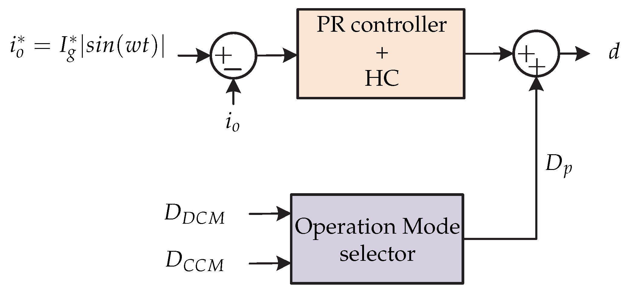
| [29] | inf() | 45°() | 2.4() | - | - | - | Fast dynamic response Harmonic frequencies elimination. Low computational burden. Elimination of disturbances. Hybrid operation(DCM-CCM). | DAB inverter | PI + RC controllers |
| [63] | - | 60°() 60°() 60°() | 3.73() | 1000() | - | - | ZCS switching capacity. Wide range of input voltages. | Flyback + active decoupling circuit + full-bridge inverter | PI controllers |
| [64] | - | - | - | - | - | - | Reactive power support. High Efficiency | LLC resonant converter + interleaved full-bridge inverter | PI controllers + RC + feedforward loop |
| [65] | - | - | - | - | - | - | Distributed control. Active and reactive power control capacity. | Cascaded full-bridge inverter | Distributed control: P + PI + PR controllers |
| [66] | - | - | Full load 4.29() Partial load 6.82() | - | - | - | Controllable power factor. High efficiency. Independent MPPT control. | Interleaved flyback converter + 3-phase Current Source Inverter | PI controllers |
| [70] | - | - | - | 0.04() | 0.2 A() | - | Two modes of operation Flyback and DAB. Reduction of switching losses. High stability. | DAB + dc-dc converter for the batteries | Dual-mode control |
| [73] | - | - | - | - | - | - | Multifunctionality. Parallel multi-mode operation. | Push–pull converter + full-bridge inverter | PI controllers |
| [74,75] | - | On-grid 89.6°() 58.6°() 87°() Off-grid 90.2°() 65.2°() 76.2°() 81.2°() | 0.05 s() | - | - | - | Ability to operate off-grid and on-grid. Reconfigurable Control. | Push–pull converter + full-bridge inverter | PI + PR controllers |
Publisher’s Note: MDPI stays neutral with regard to jurisdictional claims in published maps and institutional affiliations. |
© 2021 by the authors. Licensee MDPI, Basel, Switzerland. This article is an open access article distributed under the terms and conditions of the Creative Commons Attribution (CC BY) license (https://creativecommons.org/licenses/by/4.0/).
Share and Cite
Rojas, D.; Muñoz, J.; Rivera, M.; Rohten, J. Review of Control Techniques in Microinverters. Sensors 2021, 21, 6486. https://doi.org/10.3390/s21196486
Rojas D, Muñoz J, Rivera M, Rohten J. Review of Control Techniques in Microinverters. Sensors. 2021; 21(19):6486. https://doi.org/10.3390/s21196486
Chicago/Turabian StyleRojas, Diego, Javier Muñoz, Marco Rivera, and Jaime Rohten. 2021. "Review of Control Techniques in Microinverters" Sensors 21, no. 19: 6486. https://doi.org/10.3390/s21196486
APA StyleRojas, D., Muñoz, J., Rivera, M., & Rohten, J. (2021). Review of Control Techniques in Microinverters. Sensors, 21(19), 6486. https://doi.org/10.3390/s21196486