
A Novel Transfer Function Based Ring-Down Suppression System for PMUTs

 , , and
Abstract
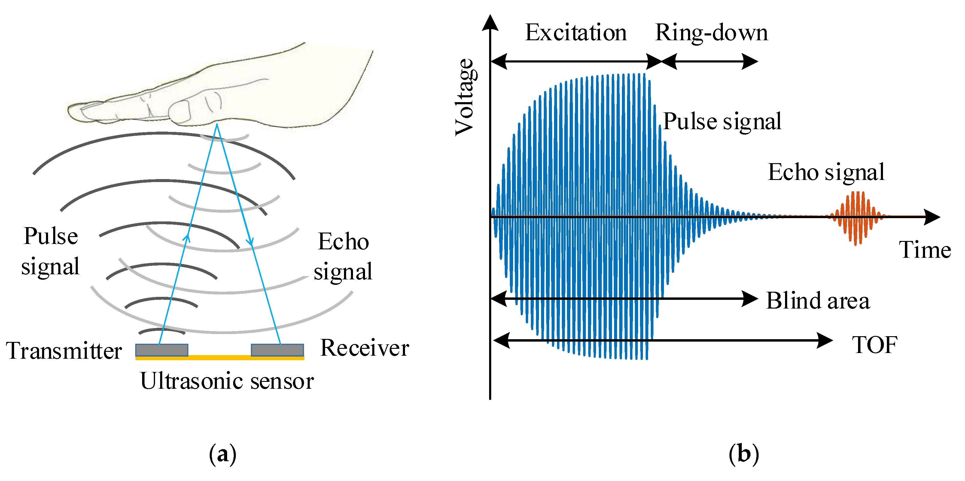
:1. Introduction
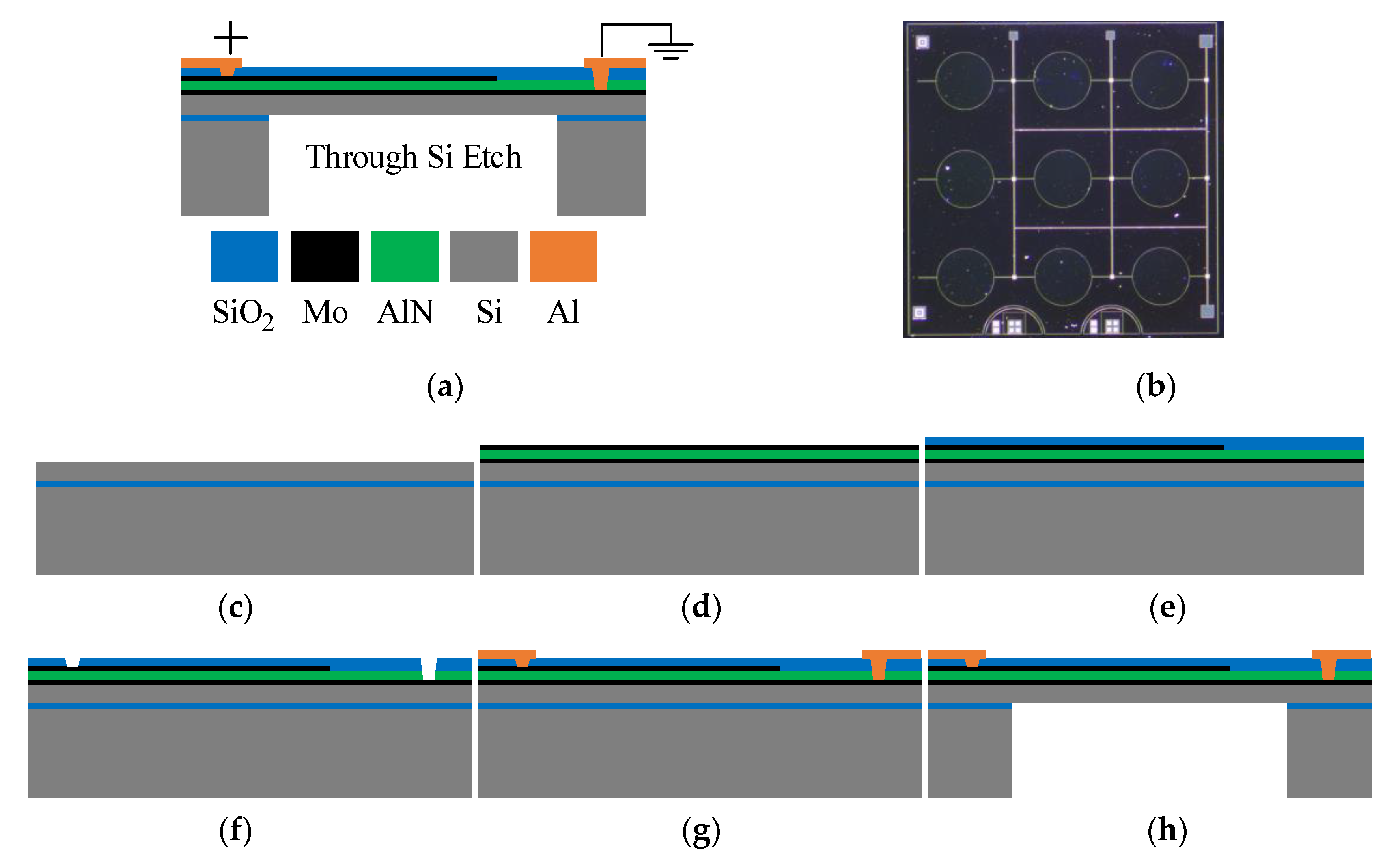
2. Structure and Characterizations of PMUTs
3. Design of The Suppression System
3.1. Transfer Function of PMUTs
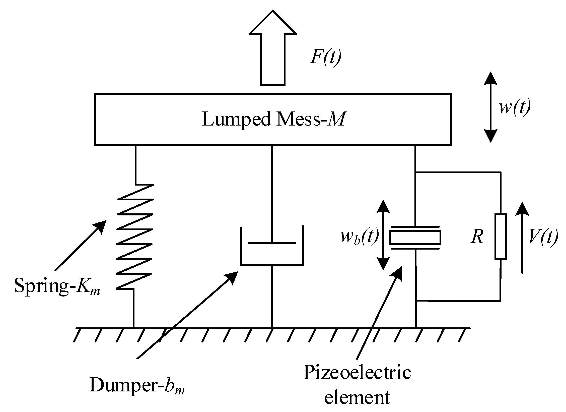
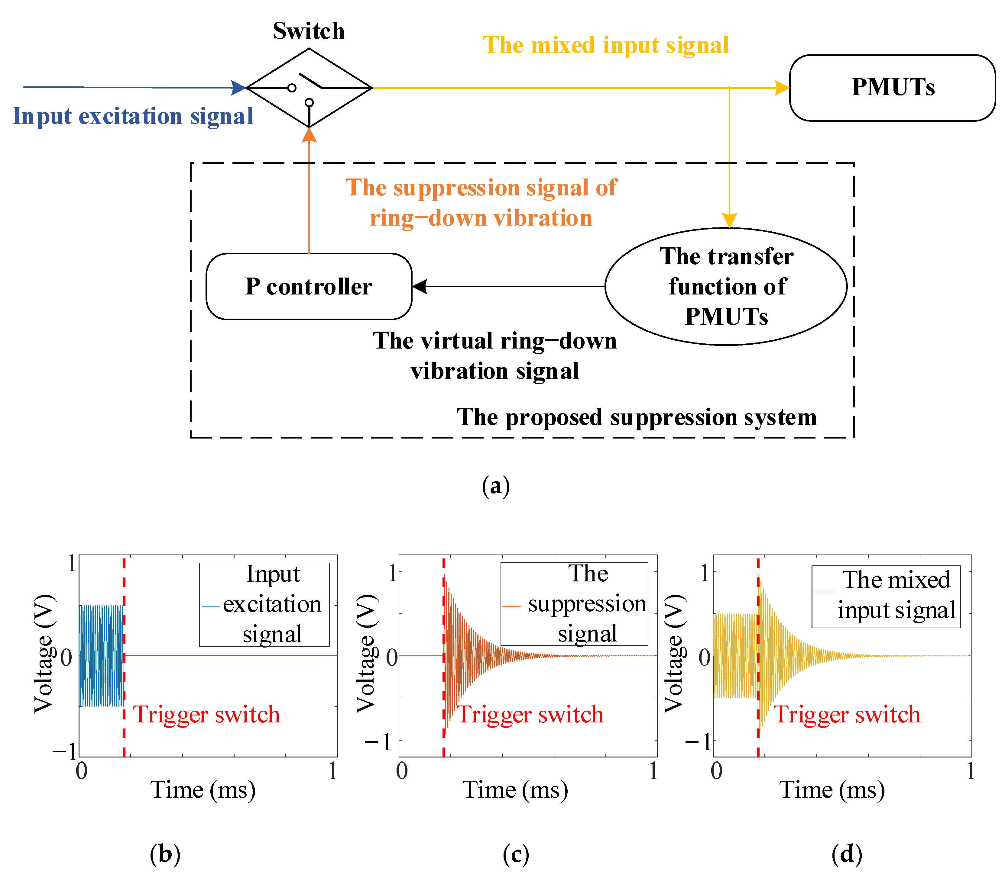
3.2. The Theory of the Suppression System
3.3. The Design of the Suppression System
4. Results and Analysis
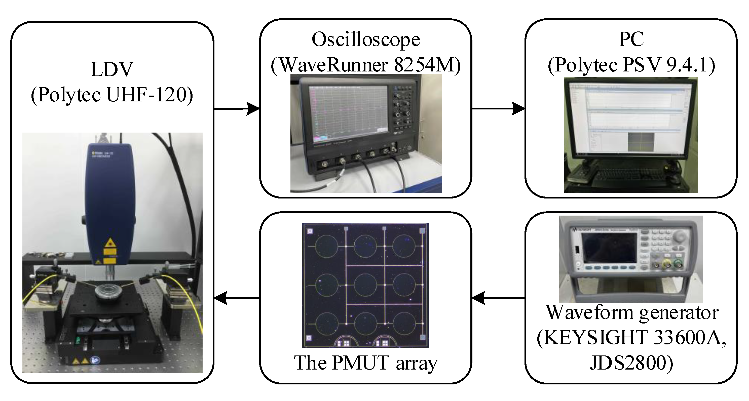
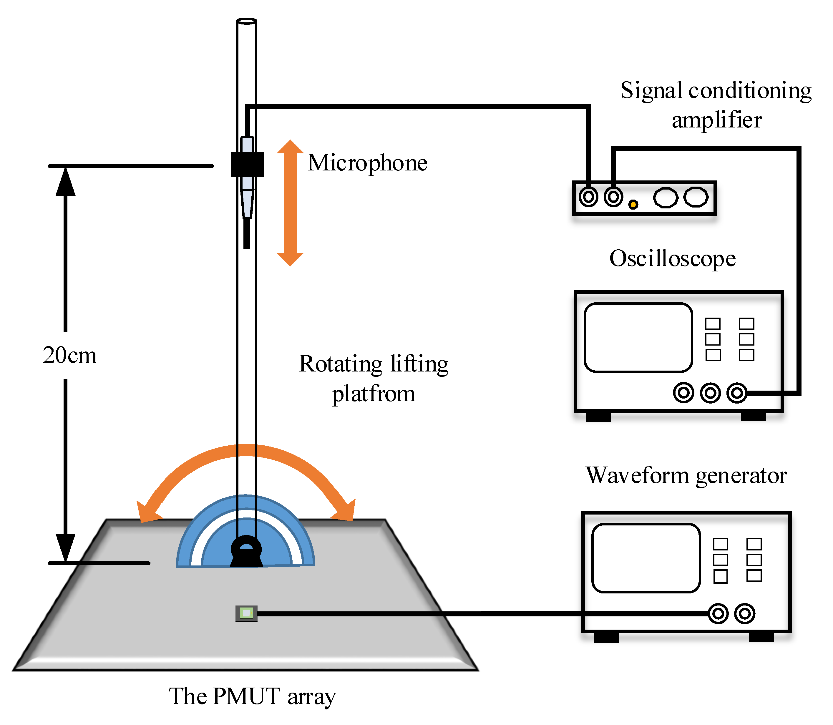
4.1. Experimental Setup
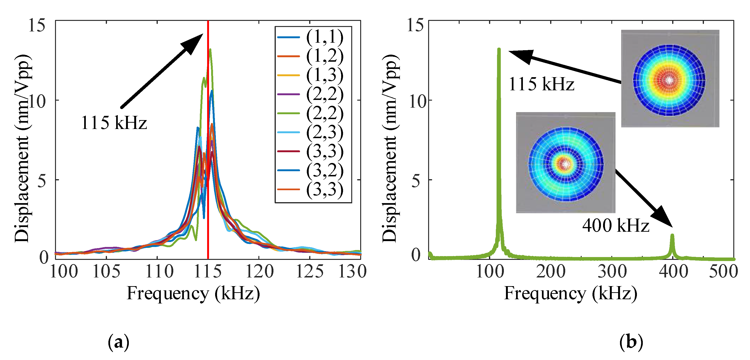
4.2. Experiment of the Transfer Function
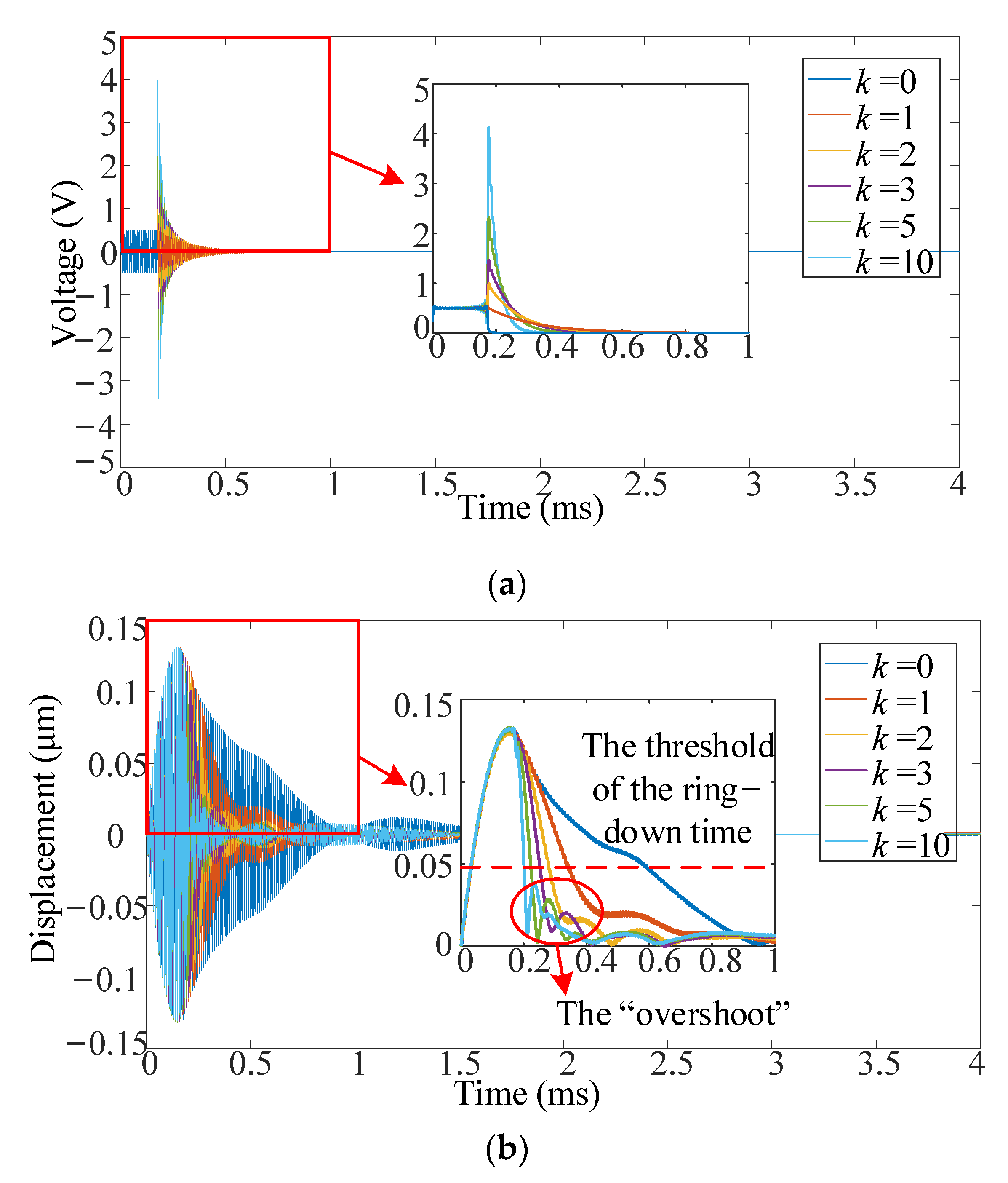
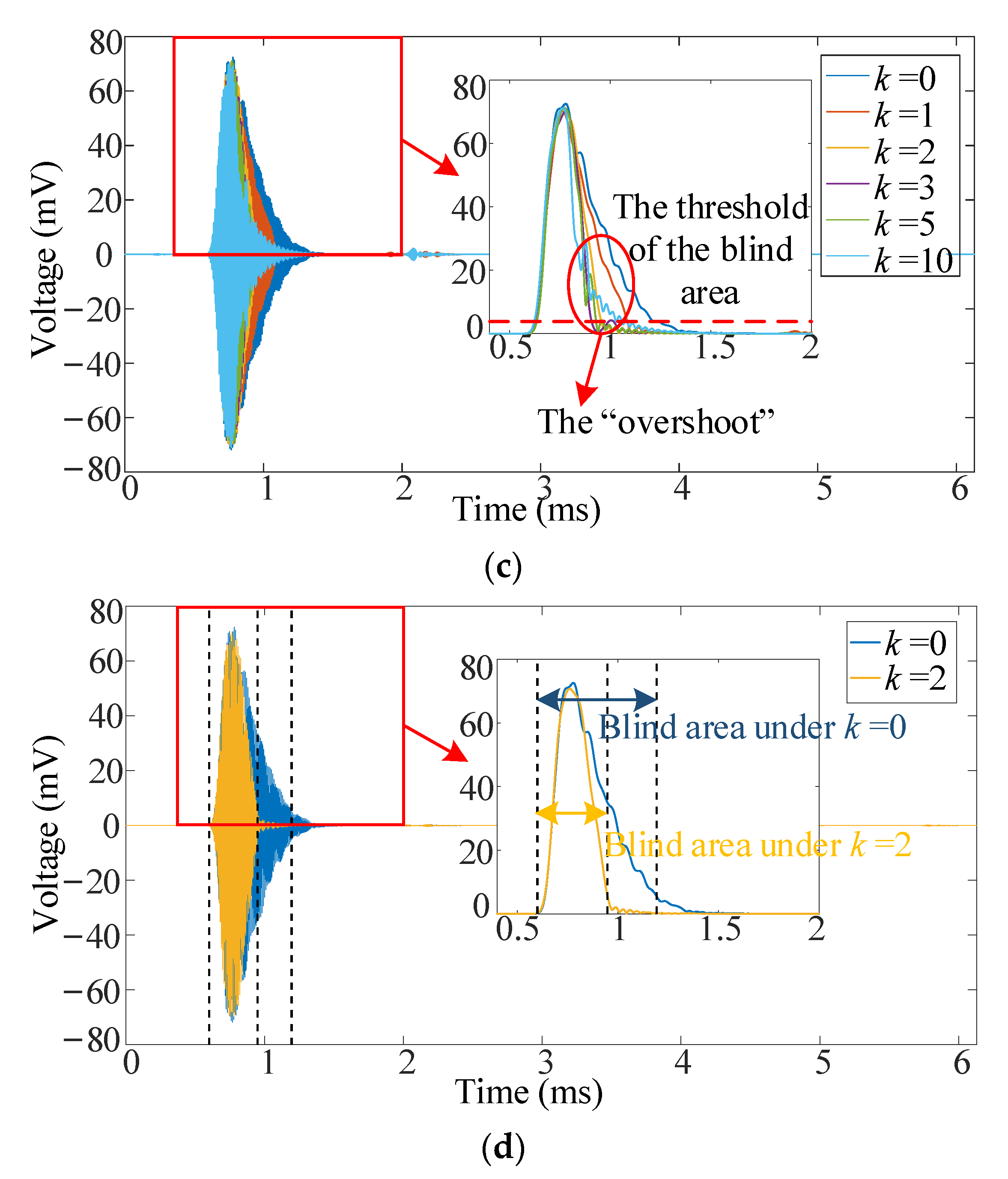
4.3. Verification of the Suppression System on Reducing the Ring-Down Time and Blind Area
5. Conclusion and Future Work
Author Contributions
Funding
Institutional Review Board Statement
Informed Consent Statement
Data Availability Statement
Acknowledgments
Conflicts of Interest
References
- Przybyla, R.J.; Shelton, S.E.; Guedes, A.; Izyumin, I.I.; Kline, M.H.; Horsley, D.A.; Boser, B.E. In-air rangefinding with an aln piezoelectric micromachined ultrasound transducer. IEEE Sens. J. 2011, 11, 2690–2697. [Google Scholar] [CrossRef]
- Przybyla, R.; Izyumin, I.; Kline, M.; Boser, B.; Shelton, S.; Guedes, A.; Horsley, D. An ultrasonic rangefinder based on an AlN piezoelectric micromachined ultrasound transducer. In Proceedings of the 2010 IEEE Sensors Conference, Kona, HI, USA, 1–4 November 2010; pp. 2417–2421. [Google Scholar]
- Przybyla, R.J.; Shelton, S.E.; Guedes, A.; Krigel, R.; Horsley, D.A.; Boser, B.E. In-air ultrasonic rangefinding and angle estimation using an array of AlN micromachined transducers. In Proceedings of the Solid-State Sensors, Actuators and Microsystems Workshop, Hilton Head Island, SC, USA, 3–7 June 2012; pp. 3–7. [Google Scholar]
- Yao, Y.; Ju, X.; Lu, J.; Men, B. Acoustic emission and echo signal compensation techniques applied to an ultrasonic logging-while-drilling caliper. Sensors 2017, 17, 1351. [Google Scholar] [CrossRef] [PubMed] [Green Version]
- Przybyla, R.J. Ultrasonic 3D rangefinder on a chip. In Doctor of Philosophy; University of California Berkeley: Berkeley, CA, USA, 2013. [Google Scholar]
- Roberto, M. Modeling and characterization of piezoelectric micromachined ultrasonic transducers (PMUT). In Master of Science; University of California Davis: Davis, CA, USA, 2019. [Google Scholar]
- Griffin, B.A.; Edstrand, A.M.; Yen, S.; Reger, R.W. Post-CMOS compatible piezoelectric micro-machined ultrasonic transducers. In Proceedings of the 2018 IEEE International Ultrasonics Symposium (IUS), Kobe, Japan, 22–25 October 2018; pp. 1–4. [Google Scholar]
- Lu, Y. Modeling, fabrication and characterization of piezoelectric micromachined ultrasonic transducer arrays. In Master of Science; University of California Davis: Davis, CA, USA, 2015. [Google Scholar]
- Jung, J.; Lee, W.; Kang, W.; Shin, E.; Ryu, J.; Choi, H. Review of piezoelectric micromachined ultrasonic transducers and their applications. J. Micromech. Microeng. 2017, 27, 11. [Google Scholar] [CrossRef]
- Muralt, P.; Baborowski, J. Micromachined ultrasonic transducers and acoustic sensors based on piezoelectric thin films. J. Electroceram. 2004, 12, 101–108. [Google Scholar] [CrossRef]
- Horsley, D.A.; Rozen, O.; Lu, Y.; Shelton, S.; Guedes, A.; Przybyla, R.; Tang, H.; Boser, B.E. Piezoelectric micromachined ultrasonic transducers for human-machine interfaces and biometric sensing. In Proceedings of the 2015 IEEE Sensors, Busan, Korea, 1–4 November 2015; pp. 1507–1510. [Google Scholar]
- Chang, K.T. Effects of a parallel resistor on electrical characteristics of a piezoelectric transformer in open-circuit transient state. IEEE Trans. Ultrason. Ferroelectr. Freq. Control 2007, 54, 107–117. [Google Scholar] [CrossRef] [PubMed]
- Chang, K.T. Improving the transient response of a bolt-clamped Langevin transducer using a parallel resistor. Ultrasonics 2003, 41, 427–436. [Google Scholar] [CrossRef]
- Hernandez, A.; Urena, J.; Mazo, M.; Garcia, J.J.; Jimenez, A.; Alvarez, F.J. Reduction of blind zone in ultrasonic transmitter/receiver transducers. Sens. Actuator. A Phys. 2007, 133, 96–103. [Google Scholar] [CrossRef]
- Liu, Q.; Bai, P.; Luo, Z.; Zhang, W.; Zhou, G. Ultrasonic distance measuring system without blind area. In Proceedings of the 2016 IEEE International Conference on Signal and Image Processing (ICSIP), Beijing, China, 13–15 August 2016; pp. 626–629. [Google Scholar]
- Liu, X.; Chen, X.; Le, X.; Wang, Y.; Wu, C.; Xie, J. Reducing ring-down time of pMUTs with phase shift of driving waveform. Sens. Actuator. A Phys. 2018, 281, 100–107. [Google Scholar] [CrossRef]
- Liu, X.; Chen, X.; Le, X.; Xu, Z.; Wu, C.; Xie, J. Optimization of pMUTs driving waveform based on phase delay to reduce attenuation vibration. In Proceedings of the 2018 IEEE 13th Annual International Conference on Nano/Micro Engineered and Molecular Systems (NEMS), Singapore, 22–26 April 2018; pp. 582–585. [Google Scholar]
- Pala, S.; Shao, Z.; Peng, Y.; Lin, L. Improved ring-down time and axial resolution of PMUTs via a phase-shift excitation scheme. In Proceedings of the 34th IEEE International conference on micro electro mechanical systems, Gainesville, FL, USA, 25–29 January 2021; pp. 390–393. [Google Scholar]
- Kusano, Y.; Wang, Q.; Luo, G.; Lu, Y.; Rudy, R.Q.; Polcawich, R.G.; Horsley, D.A. Effects of DC bias tuning on air-coupled PZT piezoelectric micromachined ultrasonic transducers. J. Microelectromech. Syst. 2018, 27, 296–304. [Google Scholar] [CrossRef]
- Kusano, Y.; Wang, Q.; Rudy, R.Q.; Polcawich, R.G.; Horsley, D.A. Wideband air-coupled PZT piezoelectric micromachined ultrasonic transducer through dc bias tuning. In Proceedings of the 30th IEEE International Conference on Micro Electro. Mechanical Systems, Las Vegas, NV, USA, 22–26 January 2017; 1204–1207. [Google Scholar]
- Tong, Z.; Hu, H.; Wu, Z.; Xie, S.; Chen, G.; Zhang, S.; Lou, L.; Liu, H. An ultrasonic proximity sensing skin for robot safety control by using piezoelectric micromachined ultrasonic transducers (PMUTs). IEEE Sens. J. 2021. [Google Scholar]
- Jiang, X.; Tang, H.; Lu, Y.; Ng, E.J.; Tsai, J.M.; Boser, B.E.; Horsley, D.A. Ultrasonic fingerprint sensor with transmit beamforming based on a PMUT array bonded to CMOS circuitry. IEEE Trans. Ultrason. Ferroelectr. Freq. Control 2017, 64, 1401–1408. [Google Scholar] [CrossRef] [PubMed]
- Sun, T.; Tasnim, F.; McIntosh, R.T.; Amiri, N.; Solav, D.; Anbarani, M.T.; Sadat, D.; Zhang, L.; Gu, Y.; Karami, M.A.; et al. Decoding of facial strains via conformable piezoelectric interfaces. Nat. Biomed. Eng. 2020, 4, 954–972. [Google Scholar] [CrossRef] [PubMed]
- Dutoit, N.E.; Wardle, B.L.; Kim, S.G. Design considerations for MEMS-scale piezoelectric mechanical vibration energy harvesters. Integr. Ferroelectr. 2005, 71, 121–160. [Google Scholar] [CrossRef]
- Lefeuvre, E.; Badel, A.; Richard, C.; Petit, L.; Guyomar, D. A comparison between several vibration-powered piezoelectric generators for standalone systems. Sens. Actuator. A-Phys. 2006, 126, 405–416. [Google Scholar] [CrossRef]
- Sina, A. Curved and bimorph piezoelectric micromachined ultrasonic transducers (PMUT). In Doctor of Philosophy; University of California Berkeley: Berkeley, CA, USA, 2016. [Google Scholar]


| Material | Top Mo | AlN | Bottom Mo | Si | SiO2 | Cavity |
|---|---|---|---|---|---|---|
| Radius (μm) | 700 | - | - | - | - | 1000 |
| Thickness (μm) | 0.2 | 1 | 0.2 | 5 | 0.5 | 400 |
| Model | Transfer Function | FED |
|---|---|---|
| 0-2 | 75.75% | |
| 1-2 | 81.61% | |
| 2-2 | 81.67% | |
| 0-3 | −24.73% | |
| 1-3 | 81.52% | |
| 2-3 | 81.48% | |
| 3-3 | 81.5% |
| k | Experiment (s) | Reduction (dB) | Relative Reduction (%) |
|---|---|---|---|
| 0 | 4.1729 × 10⁻⁴ | 0 | 0 |
| 1 | 1.6769 × 10⁻⁴ | −3.9594 | 59.8150 |
| 2 | 1.0729 × 10⁻⁴ | −5.8989 | 74.2894 |
| 3 | 7.8487 × 10⁻⁵ | −7.2564 | 81.1911 |
| 5 | 4.9687 × 10⁻⁵ | −9.2419 | 88.0929 |
| 10 | 2.8087 × 10⁻⁵ | −11.7139 | 93.2692 |
| k | Experiment (s) | Reduction (dB) | Relative Reduction (%) |
|---|---|---|---|
| 0 | 6.12 × 10⁻⁴ | 0 | 0 |
| 1 | 5.1 × 10⁻⁴ | −0.7918 | 16.6667 |
| 2 | 3.67 × 10⁻⁴ | −2.2209 | 40.0327 |
| 3 | 4.39 × 10⁻⁴ | −1.4429 | 28.2680 |
| 5 | 4.13 × 10⁻⁴ | −1.7080 | 32.5163 |
| 10 | 4.39 × 10⁻⁴ | −1.4429 | 28.2680 |
Publisher’s Note: MDPI stays neutral with regard to jurisdictional claims in published maps and institutional affiliations. |
© 2021 by the authors. Licensee MDPI, Basel, Switzerland. This article is an open access article distributed under the terms and conditions of the Creative Commons Attribution (CC BY) license (https://creativecommons.org/licenses/by/4.0/).
Share and Cite
Wu, Z.; Liu, W.; Tong, Z.; Zhang, S.; Gu, Y.; Wu, G.; Tovstopyat, A.; Sun, C.; Lou, L. A Novel Transfer Function Based Ring-Down Suppression System for PMUTs. Sensors 2021, 21, 6414. https://doi.org/10.3390/s21196414
Wu Z, Liu W, Tong Z, Zhang S, Gu Y, Wu G, Tovstopyat A, Sun C, Lou L. A Novel Transfer Function Based Ring-Down Suppression System for PMUTs. Sensors. 2021; 21(19):6414. https://doi.org/10.3390/s21196414
Chicago/Turabian StyleWu, Zhipeng, Wenjuan Liu, Zhihao Tong, Songsong Zhang, Yuandong Gu, Guoqiang Wu, Alexander Tovstopyat, Chengliang Sun, and Liang Lou. 2021. "A Novel Transfer Function Based Ring-Down Suppression System for PMUTs" Sensors 21, no. 19: 6414. https://doi.org/10.3390/s21196414
APA StyleWu, Z., Liu, W., Tong, Z., Zhang, S., Gu, Y., Wu, G., Tovstopyat, A., Sun, C., & Lou, L. (2021). A Novel Transfer Function Based Ring-Down Suppression System for PMUTs. Sensors, 21(19), 6414. https://doi.org/10.3390/s21196414