1. Introduction
The WIFI 802.11mc protocol ([
1]) allows a device to measure the distance to a WiFi Access Point (WAP) in a bi-directional communication process. The user terminal
initiates this process, and the WAP
responds to the query, which eventually results in an estimation of the distance through the Round Trip Time (RTT, details on the protocol can be found in, e.g., [
2]). As of today, the amount of devices supporting this protocol is scarce, limited to few router brands that are able to both
announce support for the 802.11mc protocol and
respond to RTT queries (examples are Compulab WILD and Google WiFi routers as well as other mesh network routers). On the
initiator side, to the authors’ best knowledge, only Google Pixel and other high end smartphones support this feature ([
3]), albeit other open platforms based on Intel chipsets have also been proposed (see, e.g., [
4,
5]).
This technology promises a breakthrough in indoor navigation, particularly in a smart city environment where smartphones are ubiquitous and applications based on this technology can enhance Location-Based Service applications ([
6]). While the benefit of this technique will be mostly evidenced in indoor environments, using RTT-based WiFi positioning could potentially be used to assist GNSS in areas with a lack of visibility (i.e., urban canyons) or to reduce the time-to-first-fix by providing a meter-level a priori position.
In addition, RTT-based positioning could serve as an alternate position provider in GNSS denied or compromised (i.e., spoofed) environments. Indeed, the measurement accuracy of the RTT ranges is on the order of tens of decimeters (see, for instance, [
7]), which certainly allows meter-level accuracy (as shown in [
8,
9,
10,
11,
12]). However, besides environmental error sources, such as multipath, RTT ranges are usually offset due to biases introduced by the WAP hardware ([
13]).
Despite this potential breakthrough, there is a clear limitation of the 802.11mc protocol due to its bi-directional nature, as opposed to other navigation systems, such as Global Navigation Satellite Systems (GNSS), that are unidirectional (i.e., user terminals only receive and do not transmit information to the satellites). The fact that an
initiator has to start a dedicated communication with the WAP limits the scalability of systems based on WiFi RTT. Some works propose methodologies to synchronize a set of WAPs so that the complete system is more GNSS-like (i.e., unidirectional, see [
2,
14]), which would enable a fully scalable solution.
Thus far, most works on WiFi RTT deal with the positioning of the user terminal using WiFi RTT or a hybridized strategy with ranging GNSS ([
15]); however, WAP positioning remains a topic to be fully investigated. An accurate estimation of the WAP position will impact the final accuracy in the user terminal, and thus lowering the WAP positioning error is critical. In previous works, WAP positions were usually obtained by survey campaigns using geodetic grade GNSS receivers (see, for instance, [
16]).
However, this solution is not practical for operational systems, and thus an automated methodology should be developed. This work intends to provide a solution based on the fact that raw GNSS measurements have been available in Android devices since 2016 ([
17]) which unlocks the possibility of having sub-metric accuracy in smartphones ([
18,
19,
20]). Therefore, geotagging the RTT measurements with a more accurate user terminal position has, in turn, the potential to better locate the position of WAPs.
In the following paper, we intend to provide a methodology to estimate the WAP position and hardware bias as well as to improve these estimates by means of exploiting the better accuracy offered by processing the raw GNSS measurements. The paper starts with a description of the data processing model and is followed by the Results section, describing the data campaign executed to test the model and the quality assessment of the estimation of WAP position and hardware bias as well as its impact in the terminal location. The paper is concluded with the Discussion section, which contains our conclusions of the work.
2. Data Processing Model
In a similar way as in other range-based navigation systems, such as GNSS (see, for instance, Section 6.1.1 of [
21]), the basic measurement to compute a receiver (
) position based on the known coordinates of a set of transmitters (
) is the range between the receiver and these transmitters. This geometric distance (
) can be computed as:
which can be linearized using a first order Taylor expansion, which requires an a priori knowledge of the element to be geolocated. Albeit this linearization can yield to biases in the estimated state, specially if the a priori is too coarse, it is needed when estimation strategies based on Kalman filtering are used [
22]. The linearization would yield the following expression:
where
is the distance between the WiFi Access Points (WAP) (i.e.,
transmitters) and the a priori position of the user terminal to geolocate (
receivers):
. A possible method to compute the approximate a priori position of the user terminal could be by means of the Bancroft method (see, for instance, Appendix D of [
23]).
In the ideal case (i.e., no biases and no measurement errors), if the user terminal measures the RTT from at least three WAPs, the position delta relative to the a priori (
)) can be solved by a simple Root Mean Square solution. While WiFi RTT ranging is a two-way communication system (as opposed to GNSS), and therefore no receiver clock has to be estimated, previous works showed that the RTT measurements were affected by an offset or bias ([
13]). Therefore, the WiFi RTT range measurement (
) is better modeled using the following expression:
where
is the
partial of the ⋄ component, defined as:
where
is the hardware bias (offset) introduced by the Access Point, as pointed out in [
13] and is expressed in meters. Finally,
is the modeled thermal (Gaussian) noise of the measurement (with standard deviation
). The user terminal position can be, therefore, estimated by solving the following linear system of
N equations (one equation per each WAP for which there is a RTT measurement):
where the
prefit residuals for the
WAP (
-
) are the measured RTT range minus the computed RTT range (using the model proposed in Equation (
3)), and
is the partial for the ⋄ component and for the
WAP.
As can be seen, to compute the user terminal, not only the WAP position but also the bias () is needed. Not adding the bias into the navigation equations will increase the error of the estimated positions.
To solve the
inverse positioning problem and obtain both the WAP location and bias (instead of the user terminal position), the linear system shown in Equation (
5) needs to be slightly reformulated as follows:
Instead of
N equations in this case we have
M measurements collected by the smartphone. These
M measurements can be taken from a single terminal at different geographical locations within the WAP area coverage or by simultaneous terminals under the WAP coverage at different locations and epochs. The combination of measurements from different terminals, locations and epochs can be done because the WAP hardware bias (
) is relatively stable over time (as noticed by the authors as well as in [
13]); therefore, measurements over different epochs can be processed in the same batch. This is slightly different than other navigation systems, such as GNSS, where the receiver clock biases depend over time, and thus measurements over different epochs have to be processed in different batches.
Clearly, the data processing model will not only need the RTT measurements as the basic observable but also the position at which this measurement was taken (i.e., the user terminal location). In smartphones, when using terminals such as Google Pixel 4, the RTT measurements can be geotagged with the position fixes provided by the Android Location Service. However, it is important to note that the error in the terminal position will directly impact the accuracy with which the WAP position can be estimated.
To improve the terminal location, other positioning algorithms can be used as shown later in this paper. Examples of such techniques include Precise Point Positioning (PPP, which uses code and carrier GNSS measurements as well as precise orbits and clocks) and Post-Processing Kinematics (PPK, which uses differential techniques with nearby GNSS reference stations). These techniques can be also applied in Android smartphones due to the fact that, since 2016, the Android API has granted access to the GNSS raw measurements to the developers (see [
17,
24]).
4. Results
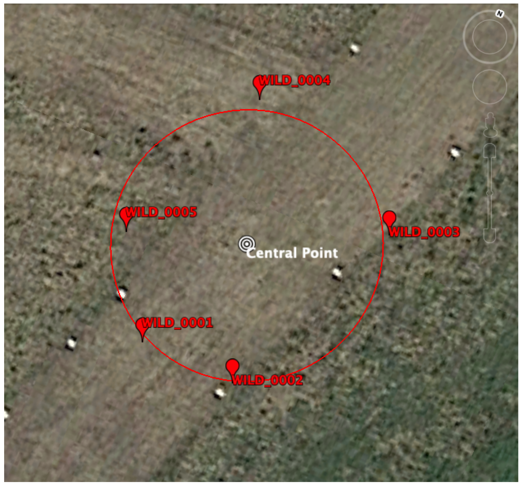
4.1. Wifi Access Point Positioning
This section contains the results of the WAP positioning estimate (as well as the hardware biases) using the processing model described above. RTT measurements from the two Google Pixel 4 smartphones were collected with a tailored app while walking around various circles outside the setup, as shown by the green line in
Figure 3.
As can be seen, the environment was open sky without obstructions. Therefore this can be considered as a benign scenario and a measure of the best possible accuracy that can be obtained using WiFi RTT measurements collected with a smartphone. A more realistic scenario will likely yield worse results due to environmental errors, such as multipath (nearby walls and obstructions), signal blockage (user holding the smartphone), and higher dynamics (turns and accelerations, …).
As mentioned before, in order to perform the inverse positioning and estimate the positions of the WAP, the RTT measurements need to have an associated position. For this work, two positions were considered: the Android position, where the position was obtained from the user terminal itself (Android Location Service), and the Jason Position, where the position was estimated using PPK computed with the GNSS measurements from the user terminal.
Due to the feature that allows extracting the GNSS raw measurements from smartphones, in particular, the carrier phase (e.g., [
29]), accessing sub-meter accuracy on those devices is possible by applying differential techniques, such as PPK (see, for instance, [
30]). The app developed as a data grabber of RTT measurements for this work contains marks for synchronisation with the GPS time scale. This feature is needed to retag those measurements with a sub-meter accuracy. To do this, the GNSS data gathered by the smartphones was uploaded to Rokubun’s Jason cloud GNSS service ([
31]) to obtain a PPK solution. The resulting position estimates (timetagged with the GPS time scale) were used to interpolate the position at the epochs where the RTT measurements were taken.
To evaluate the accuracy of the proposed
inverse positioning strategy to compute the WAP positions, the obtained positions were compared against the reference positions surveyed with the Septentrio AsteRx receiver (see
Table 1). These basic metrics were considered as performance indicators:
Position errors—essentially the horizontal and vertical errors. These errors can be computed using a tangential reference frame (East/North/Up): as is known, given a reference position and a 3D error vector, the East and North components are the projection of the error vector in the East and North directions, respectively, while the Up component is the projection of the error vector in the vertical direction. In the tangential reference frame, the vertical error (
) is directly the Up component, while the horizontal deviation (
) is defined in Equation (
7).
Hardware bias errors—computed as deviation to the reference values described in the previous section (see
Table 3).
The results for these metrics are collated in
Table 4 and
Table 5 for the two strategies to tag the RTT measurements described above (using
Android location and retagging with Jason, respectively). The most noticeable difference was due to the improvement in the horizontal error when using the Jason service (to retag the RTT measurements with the PPK position estimates): when using
Android location, errors larger than 2.5 m were obtained, while they were clearly reduced to less than 1.5 with the
Jason location.
The vertical errors were, in general, larger than the horizontal ones, but this is because of the geometry distribution of the setup. As is known from other navigation systems, such as GNSS, the Dilution-Of-Precision (DOP) causes an error amplification when the geometry of the receivers and transmitters is not
diverse (i.e., all observations aligned, see, for instance, Section 6.1.2 of [
21]).
Due to the fact that, in the proposed setup, all transmitters and receivers were in the same plane, the vertical geometry was worse than the horizontal geometry. Better vertical accuracy could have been obtained if RTT measurements above the routers were available. The DOP is usually quantified using the geometry matrix of the observations, and the lower the value is, the less error amplification. In the proposed setup, horizontal DOP of around 3 were obtained, while the vertical DOP was about 50, indicating a high difference in the geometric diversity between these two components.
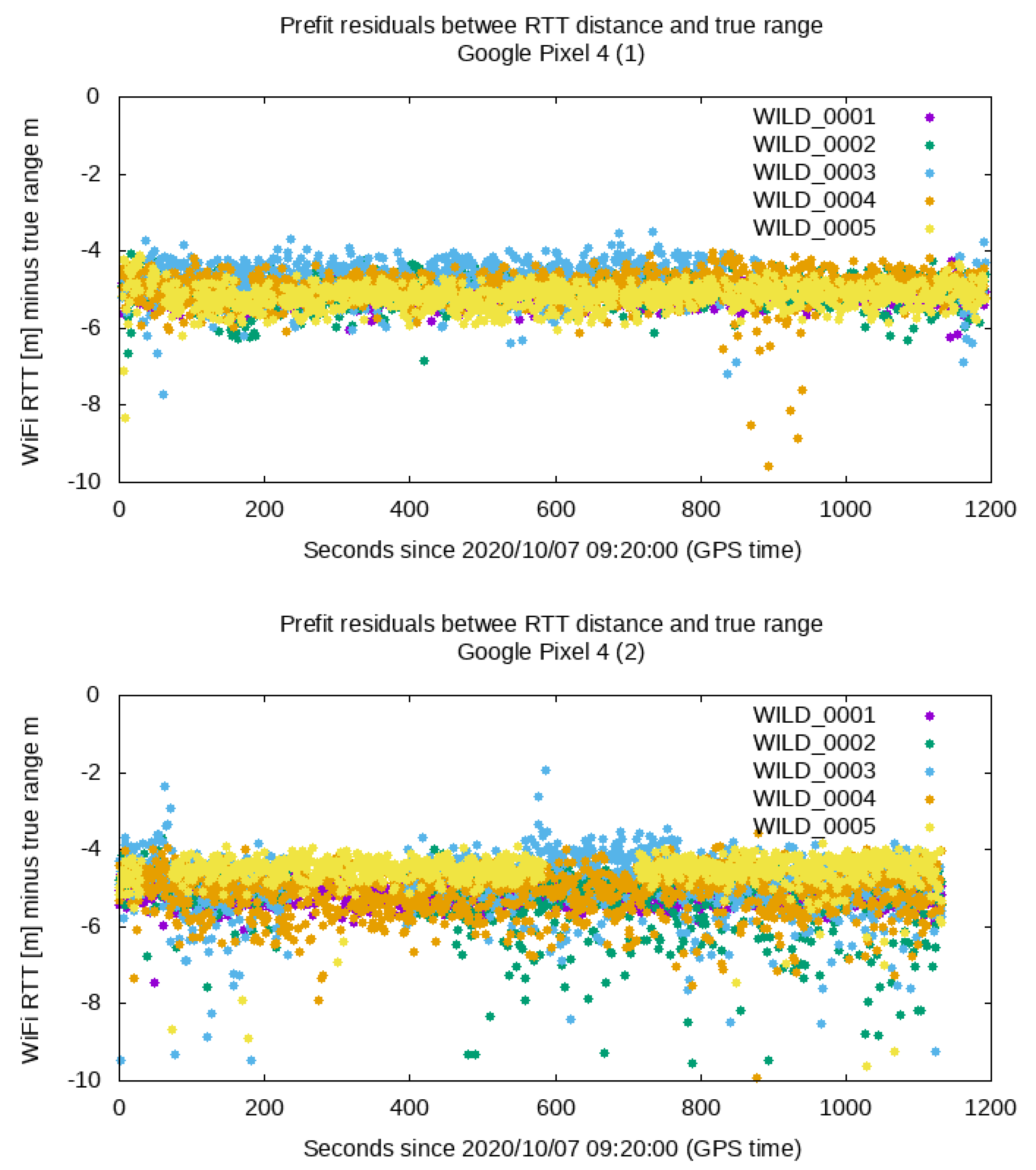
Concerning the hardware bias, in general, the resulting hardware biases were estimated within 1 to 1.5 m relative to the values provided in the previous section, and no substantial differences between both strategies were detected. However, these differences are within the same magnitude of the thermal noise error of the RTT measurements (see the last column of
Table 3 and
Figure 2).
4.2. Impact on the Terminal Accuracy
The ultimate goal of having the positions and hardware biases of the WAPs is to provide the best possible accuracy to user terminals using the RTT, particularly in areas with limited or no GNSS coverage (for instance in deep indoor environments). This section outlines the expected accuracy that can be achieved using the service based on the methodology proposed in this paper, also known as the WAP Location Service (WALS). This section is not intended to provide a full report on using WiFi RTT for user terminal navigation, as this has been widely covered in previous references (see, for instance, [
9,
10,
15] and the references therein). Rather, we intend to gauge the impact of using different sets of WAP positions and biases in the position of the user terminals.
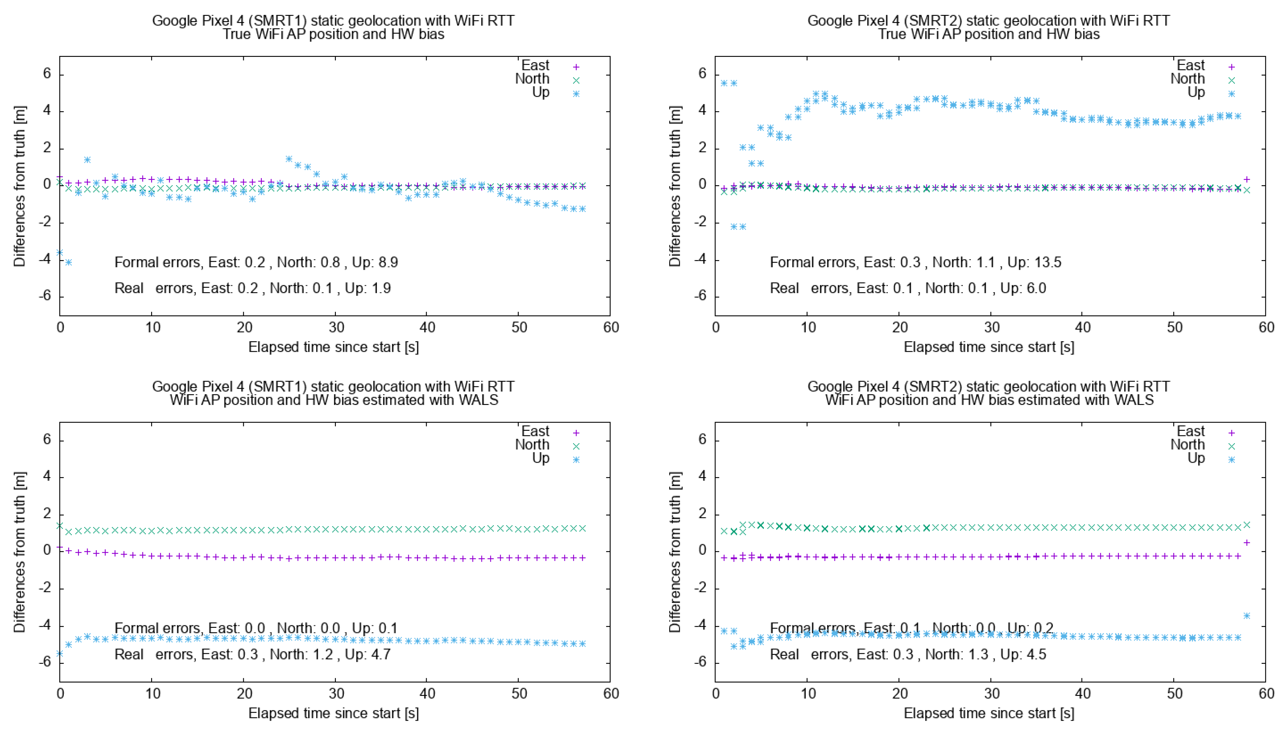
For this test, the two smartphones were placed at the Central Point. They collected Wifi RTT measurements for ca. 1 min and then were processed using Rokubun’s navigation filter using two sets of WAP coordinates and biases: (a) the ones obtained by surveying the position with the Septentrio GNSS receiver (True position) and (b) the ones obtained with the proposed service (WALS position).
The panels in
Figure 4 show the East/North/Up deviation relative to the reference position of the Central Point. The figure summarizes the results for the two smartphones used in the test, using the true positions and hardware biases (upper panels) and using the ones delivered by WALS instead (lower panels). As expected, the differences (especially in the vertical dimension) increased due to the fact that the WAP position and hardware biases delivered by WALS had estimation errors in the meter level (as reported in the previous section). However, the horizontal error was within 2 m. The vertical component showed the larger deviation due to the worse DOP in the vertical dimension, which amplifies any measurement error of the RTT ranges.
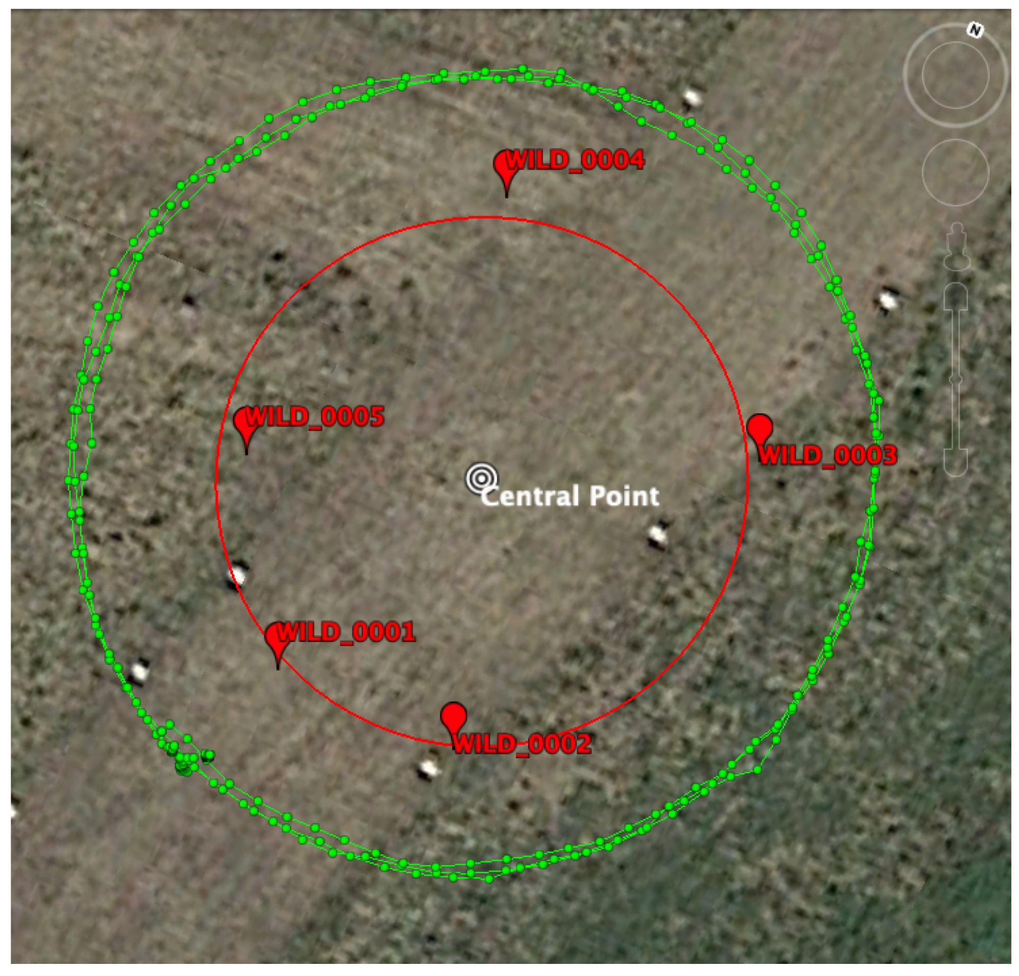
A more qualitative test can be performed in a dynamic test where the smartphones are moved around a circle with a constant radius of 15 m (similar to the green circle in
Figure 3). The results for the horizontal dimension (easting and northing) are shown in
Figure 5 for the two sets of WAP positions. As expected, the track at 15 m was better followed when more accurate WAP positions were provided (green track, using the true WAP positions) than when the positions provided by the proposed methodology (WALS) were used. However, the errors were still within the 2-m level.
5. Discussion
WiFi Round Trip Time measurements, enabled with the 802.11mc protocol, unlock the possibility of navigating with meter-level accuracy where there is no access to other navigation systems (e.g., GNSS does not work indoors). However, one key point to be able to perform this is to have accurate positions as well as the hardware (or system) biases of the WiFi Access Points (WAP). To the authors’ best knowledge, little attention has been paid so far to this problem, and previous works typically offered ad-hoc approaches, where the Access Points were surveyed with dedicated campaigns. This approach is not scalable, particularly considering the vast amount of potential RTT-capable WAPs that might appear in the future, and an automated system might be required to compute both the position as well as the biases of those WAPs.
We proposed an inverse positioning methodology by which user terminals provide the RTT ranges geotagged with the terminal position in order to estimate the position of the Access Points. Moreover, this estimation was improved using raw GNSS measurements (pseudoranges and carrier-phases) provided by the user-terminal in addition to the RTT ranges. In this case, differential GNSS techniques, such as PPK, can be used to improve the positions at which the RTT measurements were obtained causing a reduction in the error of the WAP position and hardware bias.
This process can be easily automated using an Application Programming Interface (API) of services, such as Rokubun’s Jason, which accepts GNSS data collected by smartphones and delivers the PPK position. Accuracies better than 1.5 m were achieved in the horizontal dimension, but the error in the vertical dimension increased due to a worse dilution-of-precision (DOP). In addition, The WAP biases can also be estimated with an accuracy of 1 to 1.5 m. Once the WAP positions and hardware biases are computed, they are stored in a database and served, via the API, to other users that need this data to compute their own positions in the GNSS denied environment (i.e., indoors).
It is unlikely that terminals sending data to the server to compute WAP products use these products to compute their own positions. Instead, terminals under the coverage of WAPs that are near windows in buildings (i.e., mild-indoors) will compute their locations using GNSS and then submit RTT measurements with these GNSS-based geotags.
The server will apply the inverse positioning technique to compute these mild-indoor WAP products with the accuracy level shown in this paper. At a later stage, other terminals could use these mild-indoor WAP products to compute their positions in locations without GNSS visibility (for instance well within the building, deep-indoors) and, potentially, geotag RTT measurements of other nearby WAP that are deep-indoors. These geotagged RTT measurements could be then sent to the server to compute the products of these deep-indoors WAPs, albeit with a potential decrease in accuracy.
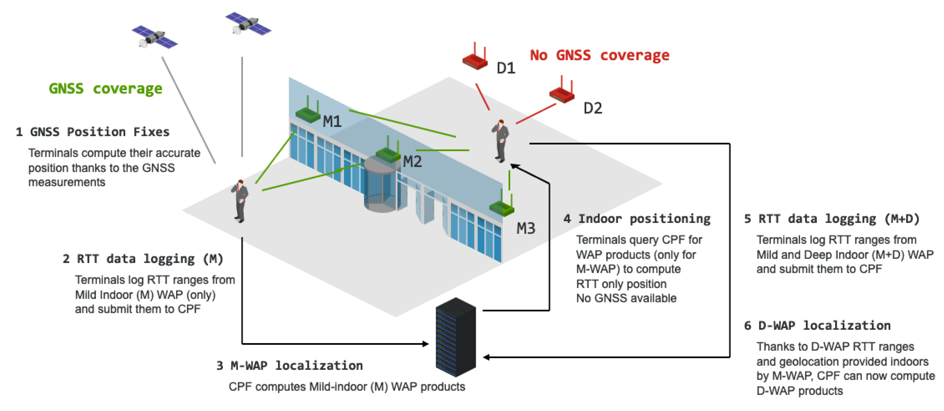
A whole system level description of an architecure using the inverse positioning technique is shown in
Figure 6. Terminals under coverage of WAPs that are near windows in buildings (i.e., mild-indoors) will compute its location using GNSS only (i.e., Wi-Fi RTT ranges may not be needed for this purpose at this stage). This user’s RTT measurements would be geotagged with this GNSS fix and then submit them to the server. The server will apply the inverse positioning technique to compute these mild-indoor WAP products with the accuracy level shown in the previous section. At a later stage, other terminals located indoors, with no GNSS visibility, could use these mild-indoor WAP products to compute its position. Eventually, the Wi-Fi only position fixes could be used to geotag RTT measurements of other nearby WAP that are deep-indoors. Note that these deep-indoor RTT measurements have not been used to compute the terminal position because, at this stage, the deep-indoor WAP products have not been yet computed and are not available to the user. Finally, these geotagged RTT measurements could be then sent to the server to compute the products of these deep-indoors WAPs.
The essential requirements in terms of hardware in order for this technique to be applicable is that terminals and WAP support Wi-Fi 802.11mc. A list of devices supporting this protocol is listed in [
3]. Regarding the Access Points, besides the one listed in this reference, modern commercial mesh systems such as Netgear Orb, Amazon Eero or Linksys Velop do support also this protocol.
In the future, additional lines for future work include an analysis of the hardware bias stability for the same device in subsequent power cycles. Moreover, more realistic studies involving indoor environments should be considered to assess the real impact of obstructions and also to assess the extent to which WAP with no outdoor visibility (such as the ones placed in deep indoor environments) can be estimated exclusively with other WAP for which their positions and hardware biases could be successfully estimated with the proposed technique (i.e., WAP near windows or mild indoors).


 ,
, 


