A 5.86 Million Quality Factor Cylindrical Resonator with Improved Structural Design Based on Thermoelastic Dissipation Analysis

Abstract
1. Introduction
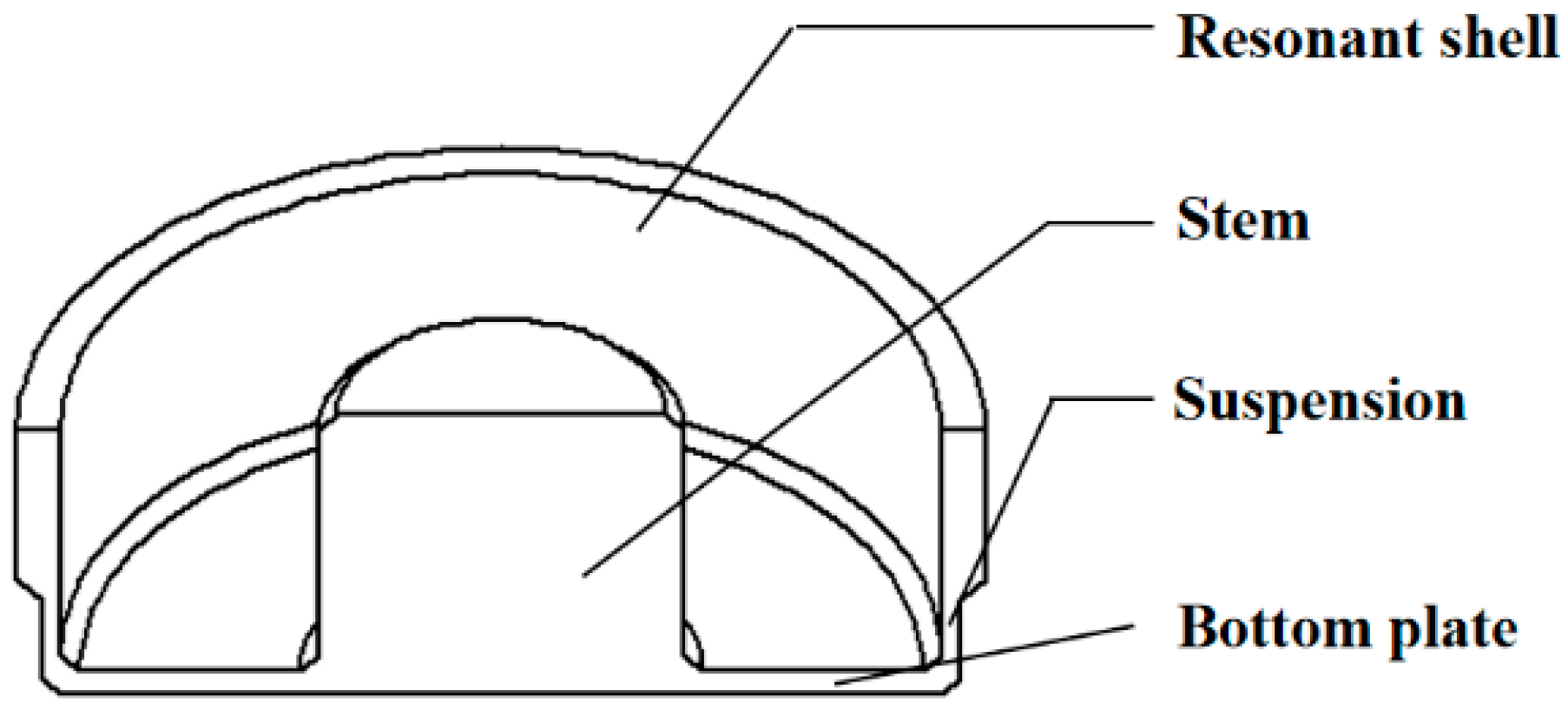
2. Simulation Model
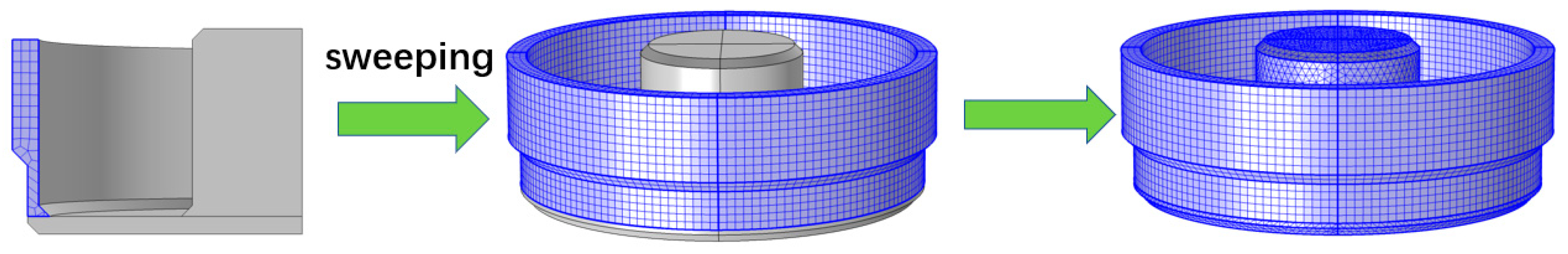
2.1. Simulation
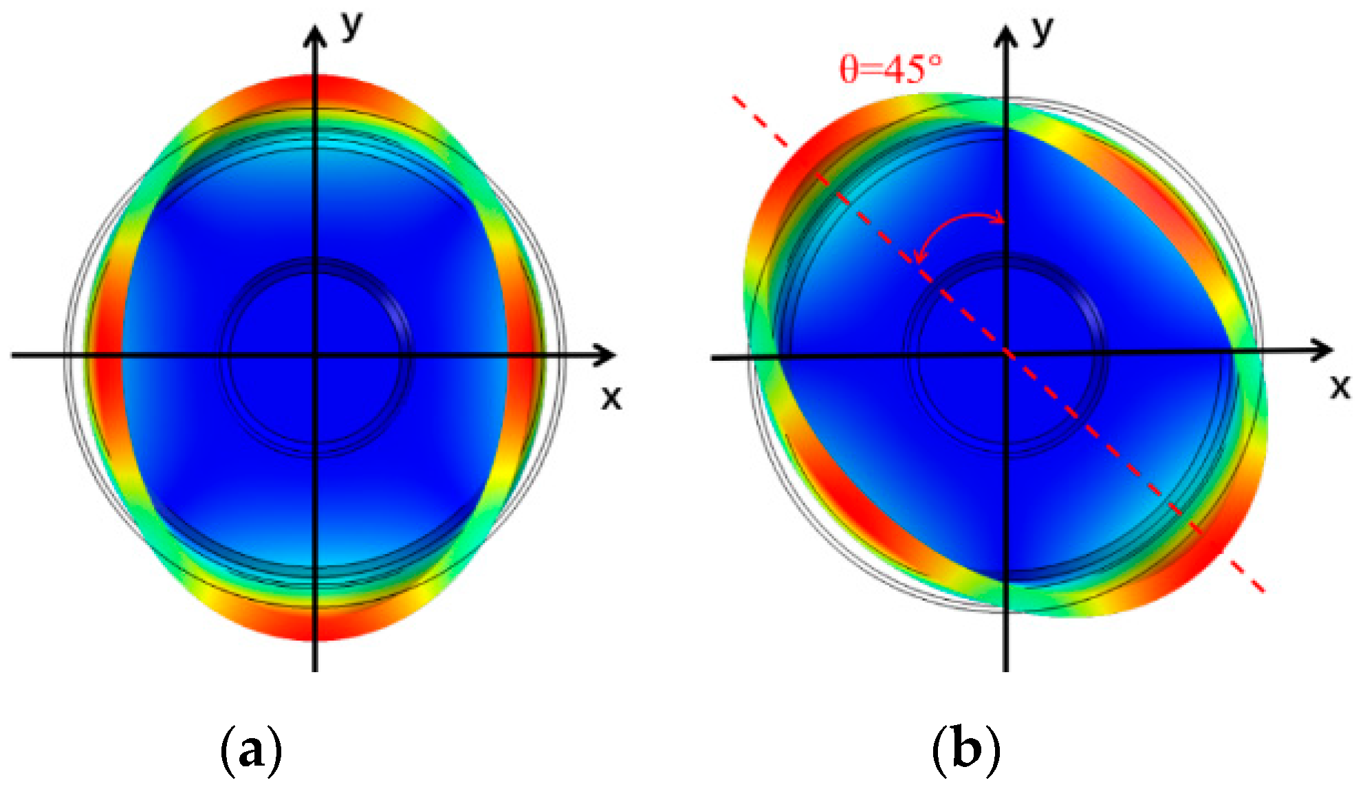
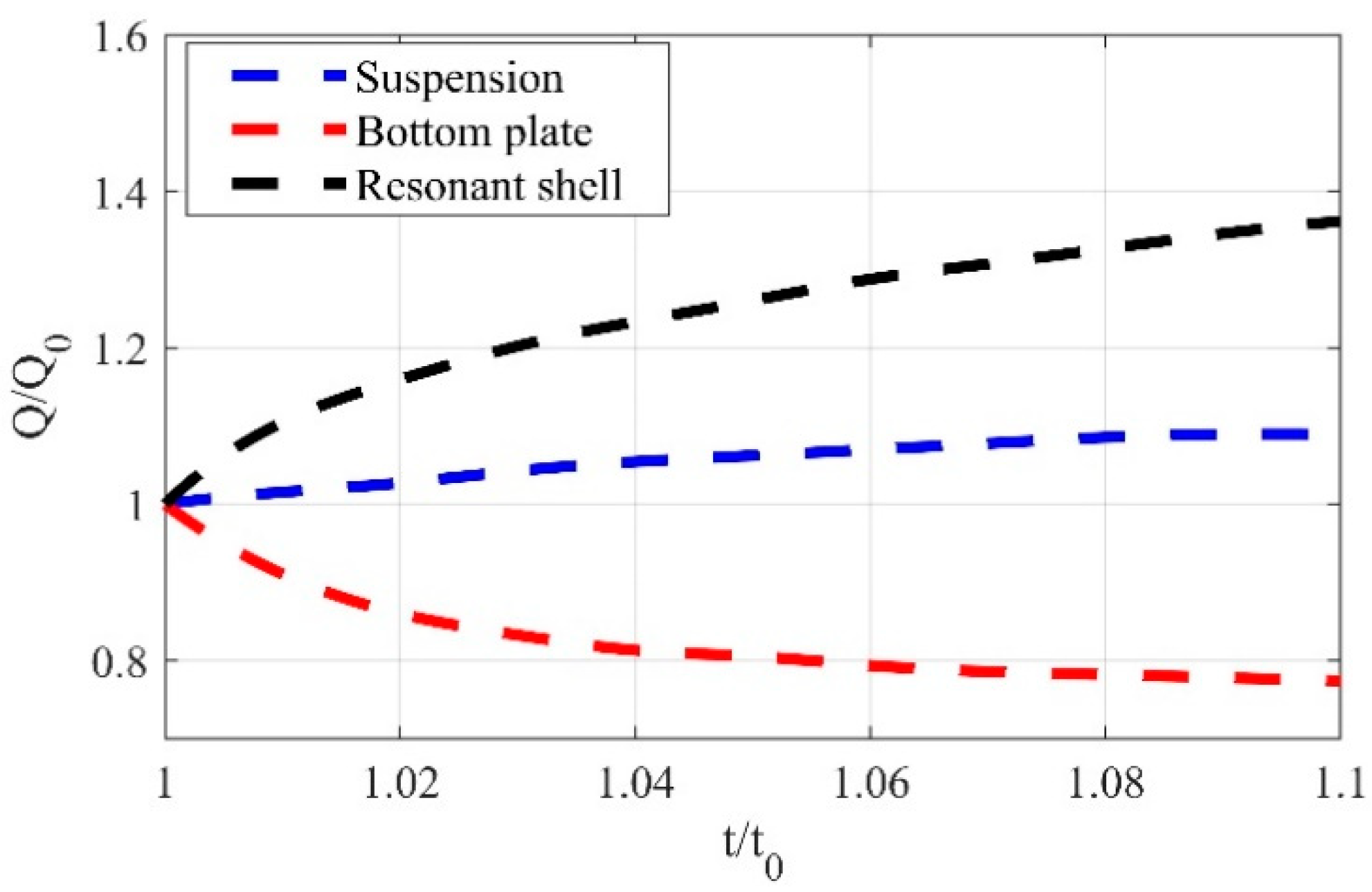
2.2. Effect of Shell Structure
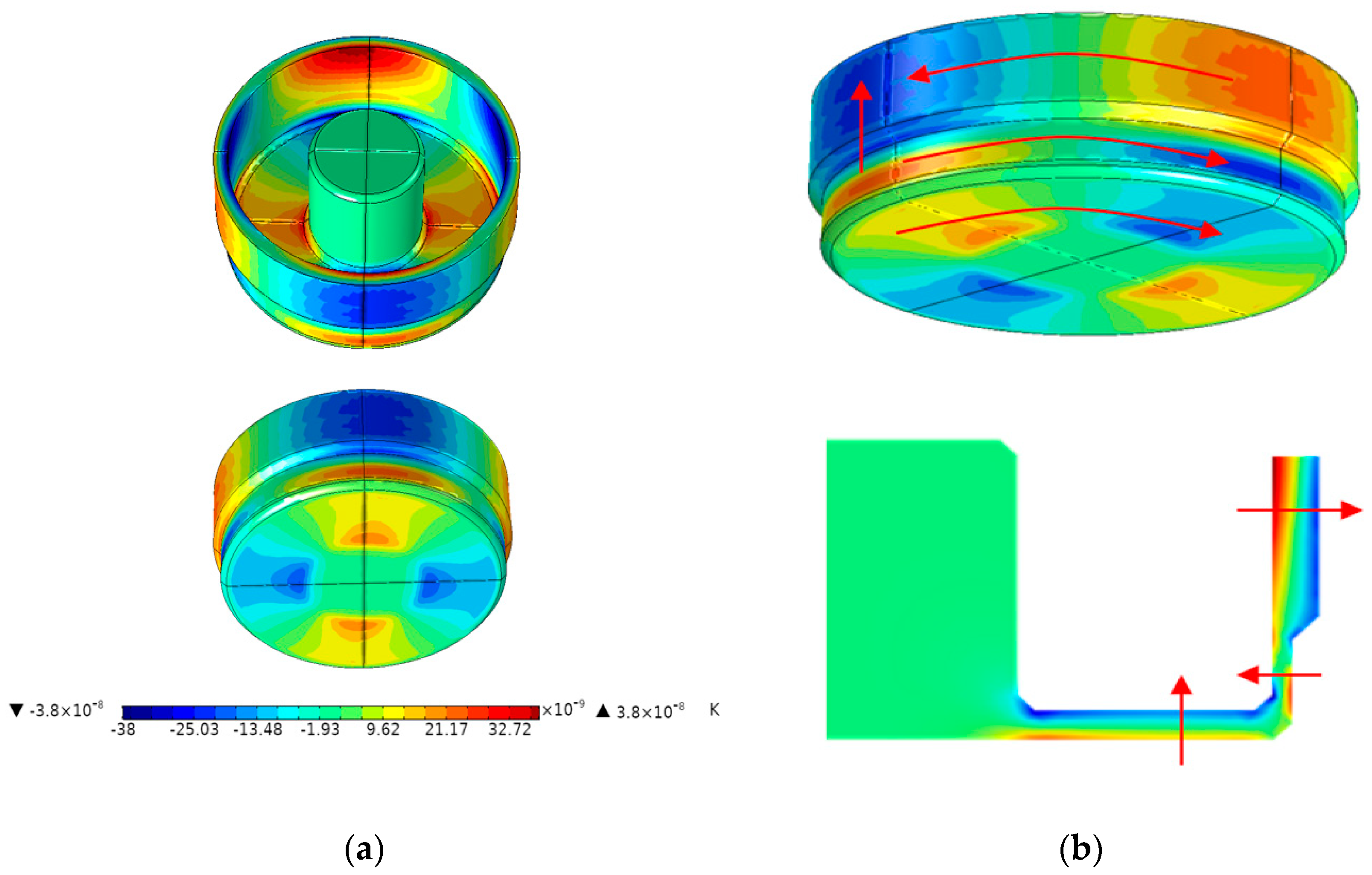
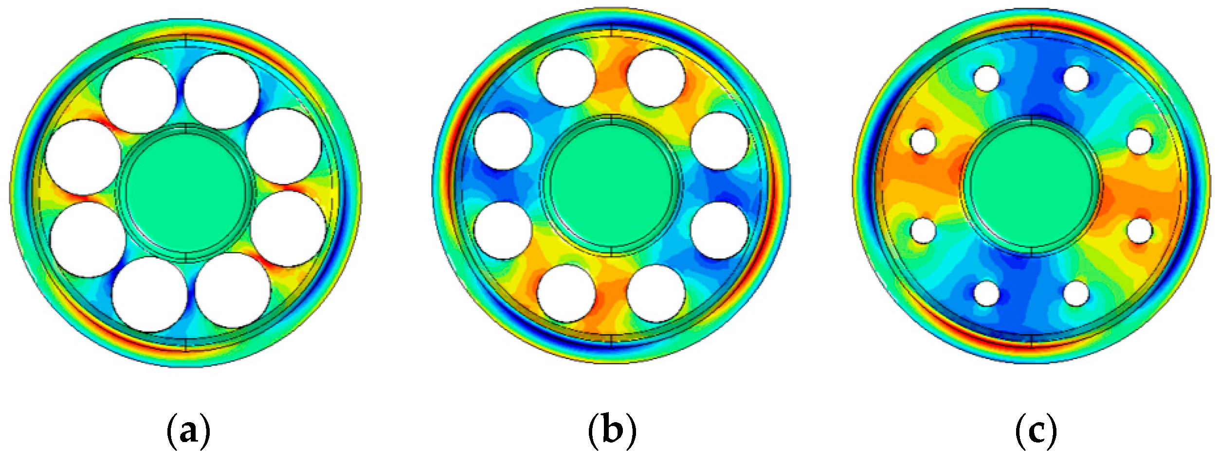
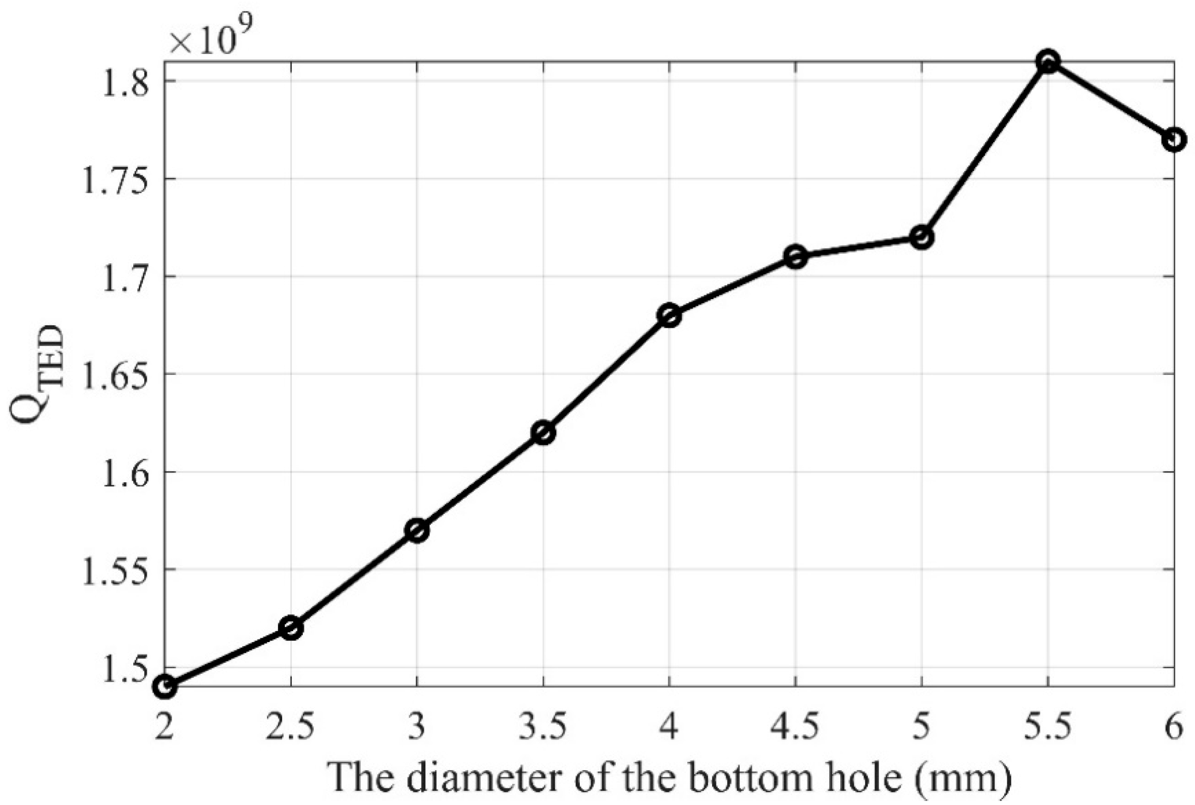
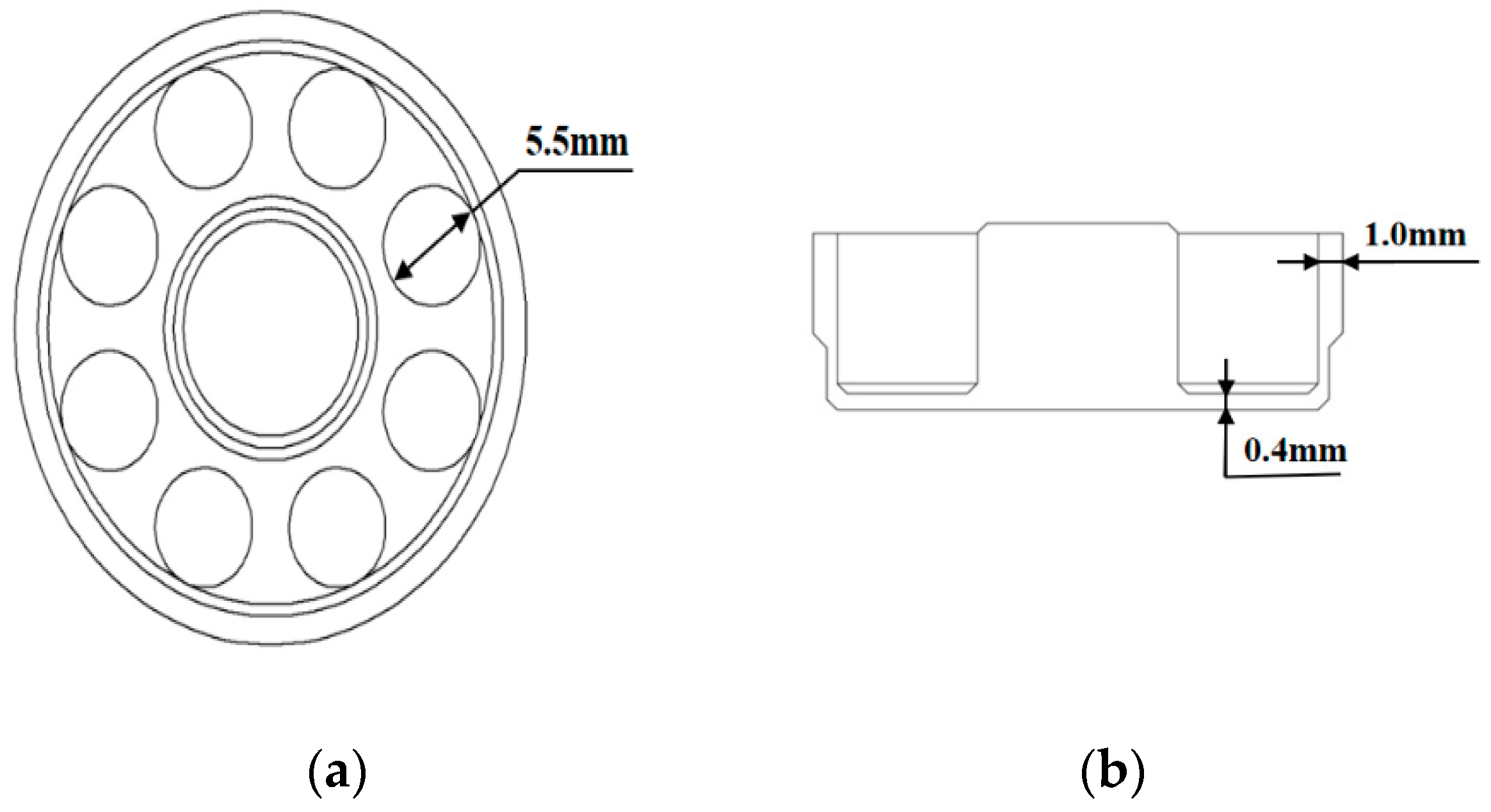
2.3. Effect of The Bottom Plate Shape
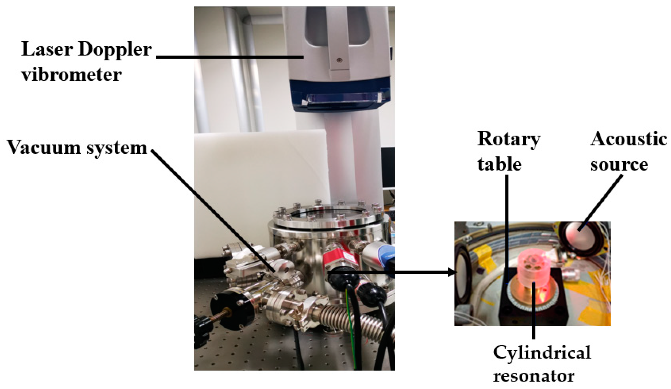
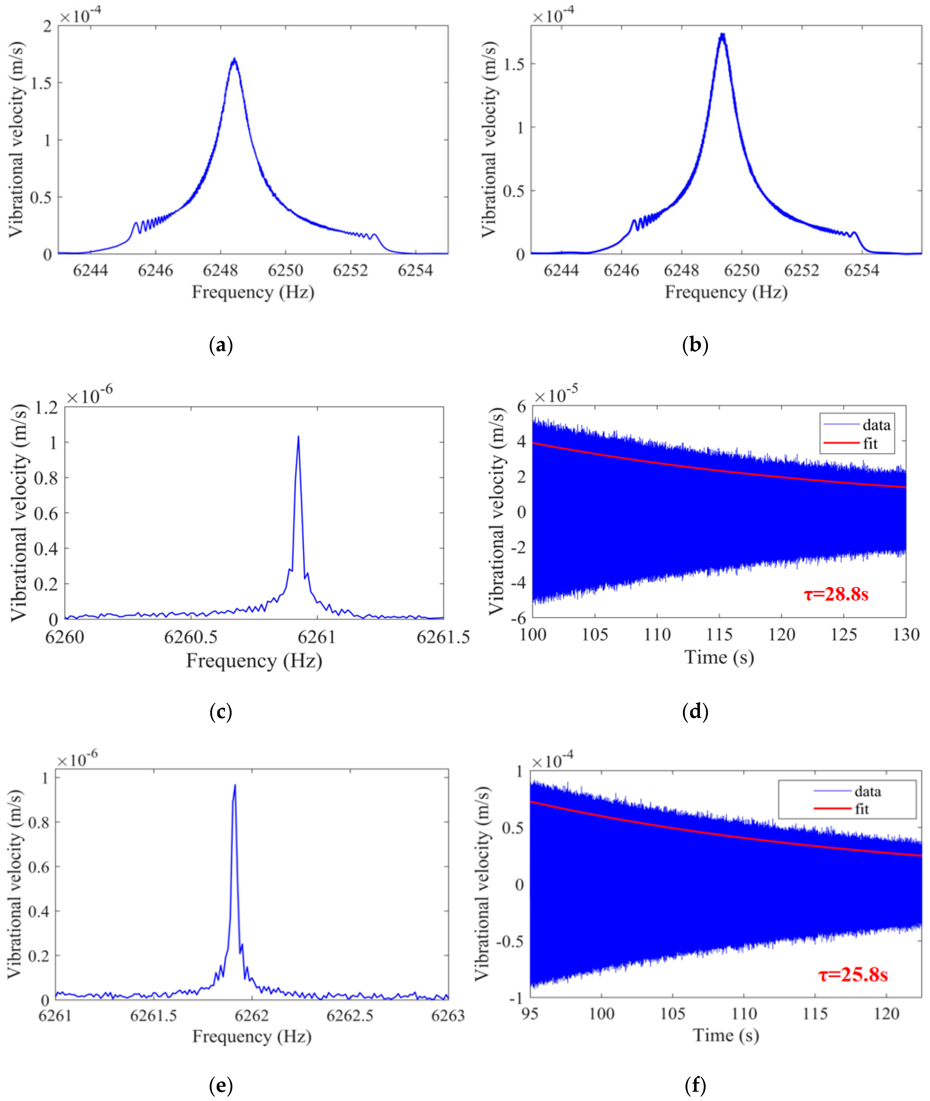
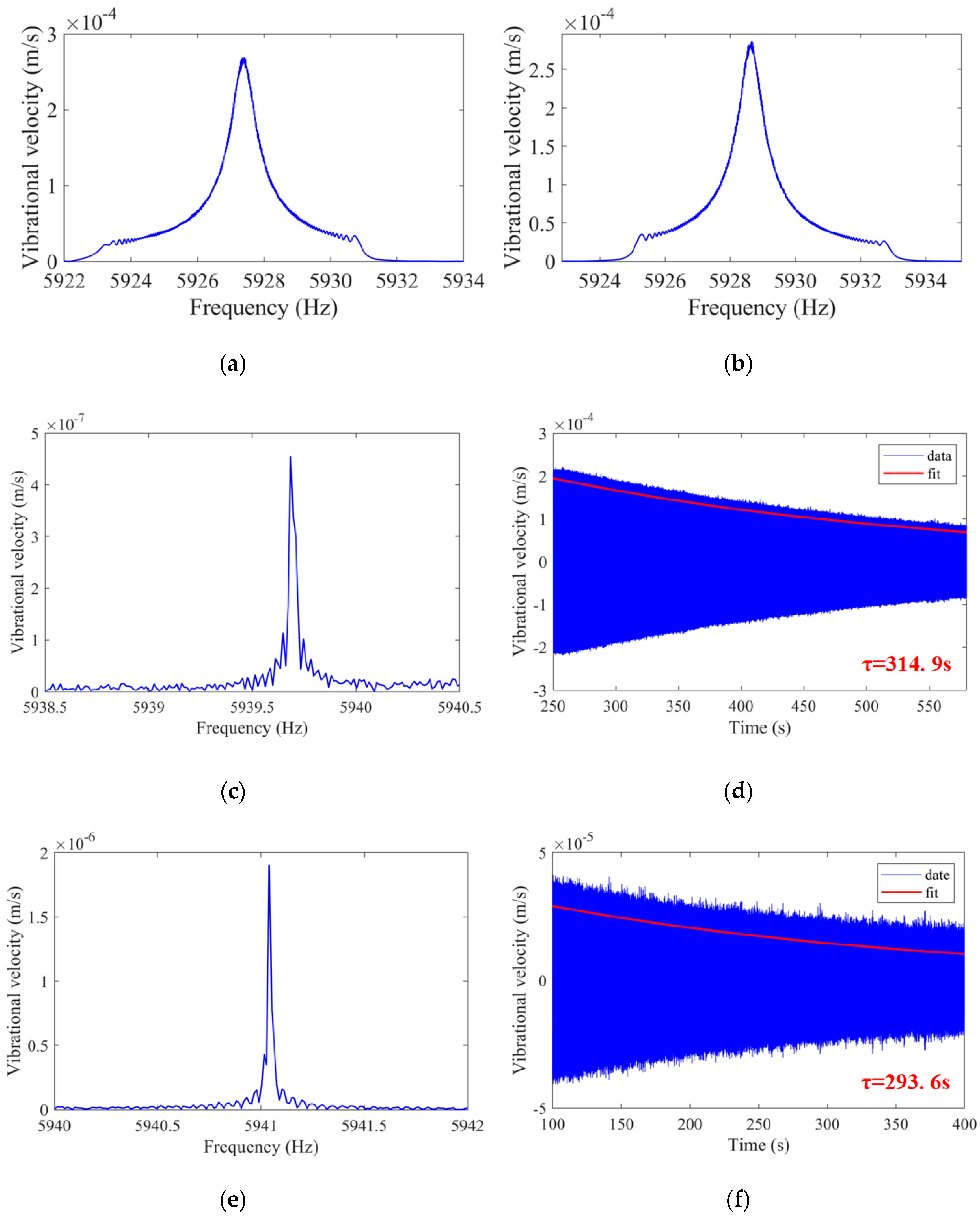
3. Experimental Result
4. Discussion
5. Conclusions
Author Contributions
Funding
Acknowledgments
Conflicts of Interest
References
- Chikovani, V.; Okon, I.M.; Barabashov, A.; Tewksbury, P. A set of high accuracy low cost metallic resonator CVG. In Proceedings of the 2008 IEEE/ION Position, Location and Navigation Symposium, Monterey, CA, USA, 5–8 May 2008; pp. 238–243. [Google Scholar] [CrossRef]
- Chikovani, V.; Yatsenko, Y.; Barabashov, A.; Marusyk, P.; Umakhanov, E.; Taturin, V. Improved accuracy metallic resonator CVG. IEEE Aerosp. Electron. Syst. Mag. 2009, 24, 40–43. [Google Scholar] [CrossRef]
- Chikovani, V.V.; Yatzenko, Y.A.; Kovalenko, V.A. Coriolis Force Gyroscope with High Sensitivity. U.S. Patent 7,513,156, 7 April 2009. [Google Scholar]
- Rozelle, D.M. The Hemispherical Resonator Gyro: From Wineglass to the Planets. In Spaceflight Mechanics, PTS I-III; Segerman, A.M., Lai, P.C., Wilkins, M.P., Pittelkau, M.E., Eds.; American Astronautical Society: San Diego, CA, USA, 2009; Volume 134, pp. 1157–1178. [Google Scholar]
- Sarapuloff, S. Development and cost reduction of high-Q dielectric resonators of solid-state gyroscopes. In Proceedings of the 8th Saint Petersburg International Conference on Integrated Navigation Systems, St. Petersburg, Russia, 28–30 May 2001; pp. 124–126. [Google Scholar]
- Sarapuloff, S.A. In Dynamics of Precise Solid-State Gyroscopes of HRG and CRG Types. In Proceedings of the V-th Brazilian Symposium on Inertial Engineering (V SBEIN), Rio de Janeiro, Brazil, 25–29 November 2007; pp. 27–29. [Google Scholar]
- Watson, W.S. Vibratory gyro skewed pick-off and driver geometry. In Proceedings of the IEEE/ION Position, Location and Navigation Symposium, Indian Wells, CA, USA, 4–6 May 2010; pp. 171–179. [Google Scholar]
- Yatsenko, Y.A.; Petrenko, S.; Vovk, V.; Chikovani, V. Technological aspects of manufacturing of compound hemispherical resonators for small-sized vibratory gyroscopes. In Proceedings of the 6 th Saint Petersburg International Conference on Integrated Navigation Systems, St. Petersburg, Russia, 24–26 May 1999. [Google Scholar]
- Northrop Grumman Corporation. Available online: https://news.northropgrumman.com/news/releases/northrop-grummans-hemispherical-resonator-gyro-achieves-50-million-operating-hours-in-space (accessed on 6 August 2019).
- Jeanroy, A.; Leger, P. Gyroscopic Sensor and Apparatus for Measuring Rotation Using Same. U.S. Patent 6,474,161B1, 5 November 2002. [Google Scholar]
- Delhaye, F. In HRG by SAFRAN: The game-changing technology. In Proceedings of the 2018 IEEE International Symposium on Inertial Sensors and Systems (INERTIAL), Moltrasio, Italy, 26–29 March 2018. [Google Scholar]
- Foloppe, Y.; Lenoir, Y. HRG Crystal™ DUAL CORE: Rebooting the INS revolution. In Proceedings of the 2019 DGON Inertial Sensors and Systems (ISS), Braunschweig, Germany, 10–11 September 2019. [Google Scholar]
- Singh, S.; Nagourney, T.; Cho, J.Y.; Darvishian, A.; Shiari, B.; Najafi, K. Design and fabrication of high-Q birdbath resonator for mems gyroscopes. In Proceedings of the 2018 IEEE/ION Position, Location and Navigation Symposium (PLANS), Monterey, CA, USA, 23–26 April 2018. [Google Scholar]
- Asadian, M.H.; Wang, D.; Wang, Y.; Shkel, A.M. 3D dual-shell micro-resonators for harsh environments. In Proceedings of the 2020 IEEE/ION Position, Location and Navigation Symposium (PLANS), Portland, OR, USA, 20–23 April 2020. [Google Scholar]
- Cho, J.Y.; Singh, S.; Woo, J.; He, G.; Najafi, K. 0.00016 deg/√hr Angle Random Walk (ARW) and 0.0014 deg/hr Bias Instability (BI) from a 5.2M-Q and 1-cm Precision Shell Integrating (PSI) Gyroscope. In Proceedings of the 2020 IEEE International Symposium on Inertial Sensors and Systems (INERTIAL), Hiroshima, Japan, 23–26 March 2020. [Google Scholar]
- Zhuravlev, V.P. Hemispherical resonator gyro with m data electrodes and n control electrodes. Mech. Solids 2015, 50, 375–378. [Google Scholar] [CrossRef]
- Wei, Z.; Yi, G.; Huo, Y.; Qi, Z.; Xu, Z. The Synthesis Model of Flat-Electrode Hemispherical Resonator Gyro. Sensors 2019, 19, 1690. [Google Scholar] [CrossRef] [PubMed]
- Pi, J.; Bang, H. Imperfection Parameter Observer and Drift Compensation Controller Design of Hemispherical Resonator Gyros. Int. J. Aeronaut. Space Sci. 2013, 14, 379–386. [Google Scholar] [CrossRef]
- Trusov, A.A.; Meyer, A.D.; Mccammon, G.H.; Bettadapura, A.; Philips, M.R. Toward software defined coriolis vibratory gyroscopes with dynamic self-calibration. In Proceedings of the 2016 DGON Intertial Sensors and Systems (ISS), Karlsruhe, Germany, 20–21 September 2016. [Google Scholar]
- Xu, Z.; Xi, B.; Yi, G.; Wang, D. A Novel Model for Fully Closed-loop System of Hemispherical Resonator Gyroscope under Force-to-Rebalance Mode. IEEE Trans. Instrum. Meas. 2020. [Google Scholar] [CrossRef]
- Xu, Z.; Yi, G.; Er, M.J.; Huang, C. Effect of Uneven Electrostatic Forces on the Dynamic Characteristics of Capacitive Hemispherical Resonator Gyroscopes. Sensors 2019, 19, 1291. [Google Scholar] [CrossRef]
- Luo, Y.; Gebrel, I.; Bognash, M.; Pan, Y.; Liu, F.; Asokanthan, S.; Luo, H.; Qu, T. Dynamic Response and Frequency Split Predictions for Cylindrical Fused Silica Resonators. IEEE Sens. J. 2020, 20, 3460–3468. [Google Scholar] [CrossRef]
- Pan, Y.; Wang, D.; Wang, Y.; Liu, J.; Wu, S.; Qu, T.; Yang, K.; Luo, H. Monolithic Cylindrical Fused Silica Resonators with High Q Factors. Sensors 2016, 16, 1185. [Google Scholar] [CrossRef]
- Luo, Y.; Qu, T.; Cui, Y.; Pan, Y.; Yu, M.; Luo, H.; Jia, Y.; Tan, Z.; Liu, J.; Zhang, B. Cylindrical Fused Silica Resonators Driven by PZT Thin Film Electrodes with Q Factor Achieving 2.89 Million after Coating. Sci. Rep. 2019, 9, 9461. [Google Scholar] [CrossRef]
- Moeenfard, H.; Ahmadian, M.T.; Farshidianfar, A. Modeling squeezed film air damping in torsional micromirrors using extended Kantorovich method. Meccanica 2012, 48, 791–805. [Google Scholar] [CrossRef]
- Yasumura, K.; Stowe, T.; Chow, E.; Pfafman, T.; Kenny, T.; Stipe, B.; Rugar, D. Quality factors in micron- and submicron-thick cantilevers. J. Microelectromech. Syst. 2000, 9, 117–125. [Google Scholar] [CrossRef]
- Hao, Z.; Erbil, A.; Ayazi, F. An analytical model for support loss in micromachined beam resonators with in-plane flexural vibrations. Sens. Actuators A Phys. 2003, 109, 156–164. [Google Scholar] [CrossRef]
- Darvishian, A.; Shiari, B.; He, G.; Najafi, K. Effect of substrate thickness on quality factor of mechanical resonators. In Proceedings of the2015 IEEE International Symposium on Inertial Sensors and Systems (ISISS), Hapuna Beach, HI, USA, 23–26 March 2015. [Google Scholar]
- Ghaffari, S.; Kenny, T.W. Thermoelastic Dissipation in Composite Silicon MEMS Resonators with Thin Film Silicon Dioxide Coating Mrs Online. Proc. Libr. 2012, 1426. [Google Scholar] [CrossRef]
- Zener, C. Internal Friction in Solids II. General Theory of Thermoelastic Internal Friction. Phys. Rev. 1938, 53, 90–99. [Google Scholar] [CrossRef]
- Braginsky, V.B.; Mitrofanov, V.P.; Panov, V.I.; Hetherington, J.H. Systems with Small Dissipation (First published in Moscow in 1981 as “Sistemis Maloi Dissipatsiei”) by V. B. Braginsky, V.P. Mitrofanov, and V. I. Panov (Translated by Erast Gliner). J. Acoust. Soc. Am. 1987, 81, 1652. [Google Scholar] [CrossRef]
- Shiari, B.; Nagourney, T.; Darvishian, A.; Cho, J.Y.; Najafi, K. Numerical study of impact of surface roughness on thermoelastic loss of micro-resonators. 2017 IEEE International Symposium on Inertial Sensors and Systems (INERTIAL), Kauai, HI, USA, 27–30 March 2017; pp. 74–77. [Google Scholar] [CrossRef]
- Sorenson, L.; Shao, P.; Ayazi, F. Bulk and Surface Thermoelastic Dissipation in Micro-Hemispherical Shell Resonators. J. Microelectromech. Syst. 2014, 24, 486–502. [Google Scholar] [CrossRef]
- Darvishian, A.; Nagourney, T.; Cho, J.Y.; Shiari, B.; Najafi, K. Thermoelastic Dissipation in Micromachined Birdbath Shell Resonators. J. Microelectromech. Syst. 2017, 26, 758–772. [Google Scholar] [CrossRef]
- Hao, Z.; Ayazi, F. Thermoelastic Damping in Flexural-Mode Ring Gyroscopes. Adv. Bioeng. 2005, 7, 335–343. [Google Scholar]
- Hamza, A.; Tsukamoto, T.; Tanaka, S. Quality factor trimming method using thermoelastic dissipation for ring-shape MEMS resonator. In Proceedings of the 2020 IEEE International Symposium on Inertial Sensors and Systems (INERTIAL), Hiroshima, Japan, 23–26 March 2020. [Google Scholar]
- Moeenfard, H.; Kaji, F.; Ahmadian, M.T. Coupled bending and torsion effects on the squeezed film air damping in torsional micromirrors. In Proceedings of the 6th International Conference on Micro- and Nanosystems; 17th Design for Manufacturing and the Life Cycle Conference, Chicago, IL, USA, 12–15 August 2012. [Google Scholar]
- Bernstein, J.J.; Bancu, M.G.; Bauer, J.M.; Cook, E.H.; Kumar, P.; Newton, E.; Nyinjee, T.; Perlin, G.E.; Ricker, J.A.; Teynor, W.A.; et al. High Q diamond hemispherical resonators: Fabrication and energy loss mechanisms. J. Micromech. Microeng. 2015, 25. [Google Scholar] [CrossRef]
- Vafanejad, A.; Kim, E.S. Effect of diaphragm perforation on quality factor of hemispherical resonator gyroscope. Proceedings of 2015 Transducers–2015 18th International Conference on Solid-State Sensors, Actuators and Microsystems (TRANSDUCERS), Anchorage, AK, USA, 21–25 June 2015. [Google Scholar]
- Luo, Y.; Pan, Y.; Zhou, G.; Qu, T.; Luo, H.; Zhang, B. Annealing experiments on the quality factor of fused silica cylindrical shell resonator. In Proceedings of the 2019 IEEE International Symposium on Inertial Sensors and Systems (INERTIAL), Naples, FL, USA, 1–5 April 2019. [Google Scholar]
- Ahamed, M.J.; Senkal, D.; Shkel, A.M. Effect of annealing on mechanical quality factor of fused quartz hemispherical resonator. In Proceedings of the 2014 International Symposium on Inertial Sensors and Systems (ISISS), Laguna Beach, CA, USA, 25–26 February 2014. [Google Scholar]
- Nagourney, T.; Cho, J.Y.; Darvishian, A.; Shiari, B.; Najafi, K. Effect of metal annealing on the Q-factor of metal- coated fused silica micro shell resonators. In Proceedings of the 2015 IEEE International Symposium on Inertial Sensors and Systems (ISISS) Proceedings; Institute of Electrical and Electronics Engineers (IEEE), Hapuna Beach, HI, USA, 23–26 March 2015; pp. 1–5. [Google Scholar]
- Li, S.; Wang, Z.; Wu, Y. Relationship between subsurface damage and surface roughness of optical materials in grinding and lapping processes. J. Mater. Process. Technol. 2008, 205, 34–41. [Google Scholar] [CrossRef]
- Davis, K.; Tomozawa, M. Water diffusion into silica glass: Structural changes in silica glass and their effect on water solubility and diffusivity. J. Non-Cryst. Solids 1995, 185, 203–220. [Google Scholar] [CrossRef]
- Hed, P.P.; Edwards, D.F. Optical glass fabrication technology 2: Relationship between surface roughness and subsurface damage. Appl. Opt. 1987, 26, 4677–4680. [Google Scholar] [CrossRef] [PubMed]
- Miller, P.E.; Suratwala, T.; Wong, L.L.; Feit, M.D.; Menapace, J.A.; Davis, P.J.; Steele, R.A. The distribution of subsurface damage in fused silica. In Proceedings of the Boulder Damage Symposium XXXVII: Annual Symposium on Optical Materials for High Power Lasers, Boulder, CO, USA, 19–21 September 2005. [Google Scholar] [CrossRef]
- Mitrofanov, V.; Tokmakov, K. Effect of heating on dissipation of mechanical energy in fused silica fibers. Phys. Lett. A 2003, 308, 212–218. [Google Scholar] [CrossRef]
- Suratwala, T.; Wong, L.; Miller, P.; Feit, M.; Menapace, J.; Steele, R.; Davis, P.; Walmer, D. Sub-surface mechanical damage distributions during grinding of fused silica. J. Non-Cryst. Solids 2006, 352, 5601–5617. [Google Scholar] [CrossRef]
- Suratwala, T.; Steele, R.; Feit, M.; Wong, L.; Miller, P.; Menapace, J.; Davis, P. Effect of rogue particles on the sub-surface damage of fused silica during grinding/polishing. J. Non-Cryst. Solids 2008, 354, 2023–2037. [Google Scholar] [CrossRef]
- Zhai, Y.J.; Pan, Y.; Jia, Y.L.; Liu, J.P.; Tan, Z.Q.; Yang, K.Y.; Luo, H. Surface evolution of cylindrical fused silica resonator and its implication on Q factor. In Proceedings of the 2019 DGON Inertial Sensors and Systems (ISS), Braunschweig, Germany, 10–11 September 2019. [Google Scholar]


| Component | Value | Units |
|---|---|---|
| Young’s modulus (E) | 72 | GPa |
| Density () | 2200 | kg/m3 |
| Specific heat capacity (C) | 770 | J/(kg K) |
| Thermal conductivity (k) | 1.38 | W/(m K) |
| Coefficient of thermal expansion () | 5.2 × 10⁻⁷ | 1/K |
| Poisson’s ratio () | 0.18 |
| Annealing Process | Heating Process | Heat Preservation | Cooling Process | ||
|---|---|---|---|---|---|
| Temperature | Heating Rate | Temperature/Time | Temperature | Cooling Rate | |
| Parameter | <800 °C | 10 °C/min | 1150 °C | 900 °C | 0.5 °C/min |
| 1150 °C | 4 °C/min | 8 h | ≤800 °C | Free cooling | |
Publisher’s Note: MDPI stays neutral with regard to jurisdictional claims in published maps and institutional affiliations. |
© 2020 by the authors. Licensee MDPI, Basel, Switzerland. This article is an open access article distributed under the terms and conditions of the Creative Commons Attribution (CC BY) license (http://creativecommons.org/licenses/by/4.0/).
Share and Cite
Zeng, L.; Luo, Y.; Pan, Y.; Jia, Y.; Liu, J.; Tan, Z.; Yang, K.; Luo, H. A 5.86 Million Quality Factor Cylindrical Resonator with Improved Structural Design Based on Thermoelastic Dissipation Analysis. Sensors 2020, 20, 6003. https://doi.org/10.3390/s20216003
Zeng L, Luo Y, Pan Y, Jia Y, Liu J, Tan Z, Yang K, Luo H. A 5.86 Million Quality Factor Cylindrical Resonator with Improved Structural Design Based on Thermoelastic Dissipation Analysis. Sensors. 2020; 20(21):6003. https://doi.org/10.3390/s20216003
Chicago/Turabian StyleZeng, Libin, Yiming Luo, Yao Pan, Yonglei Jia, Jianping Liu, Zhongqi Tan, Kaiyong Yang, and Hui Luo. 2020. "A 5.86 Million Quality Factor Cylindrical Resonator with Improved Structural Design Based on Thermoelastic Dissipation Analysis" Sensors 20, no. 21: 6003. https://doi.org/10.3390/s20216003
APA StyleZeng, L., Luo, Y., Pan, Y., Jia, Y., Liu, J., Tan, Z., Yang, K., & Luo, H. (2020). A 5.86 Million Quality Factor Cylindrical Resonator with Improved Structural Design Based on Thermoelastic Dissipation Analysis. Sensors, 20(21), 6003. https://doi.org/10.3390/s20216003