A Compact and Flexible UHF RFID Tag Antenna for Massive IoT Devices in 5G System


Abstract
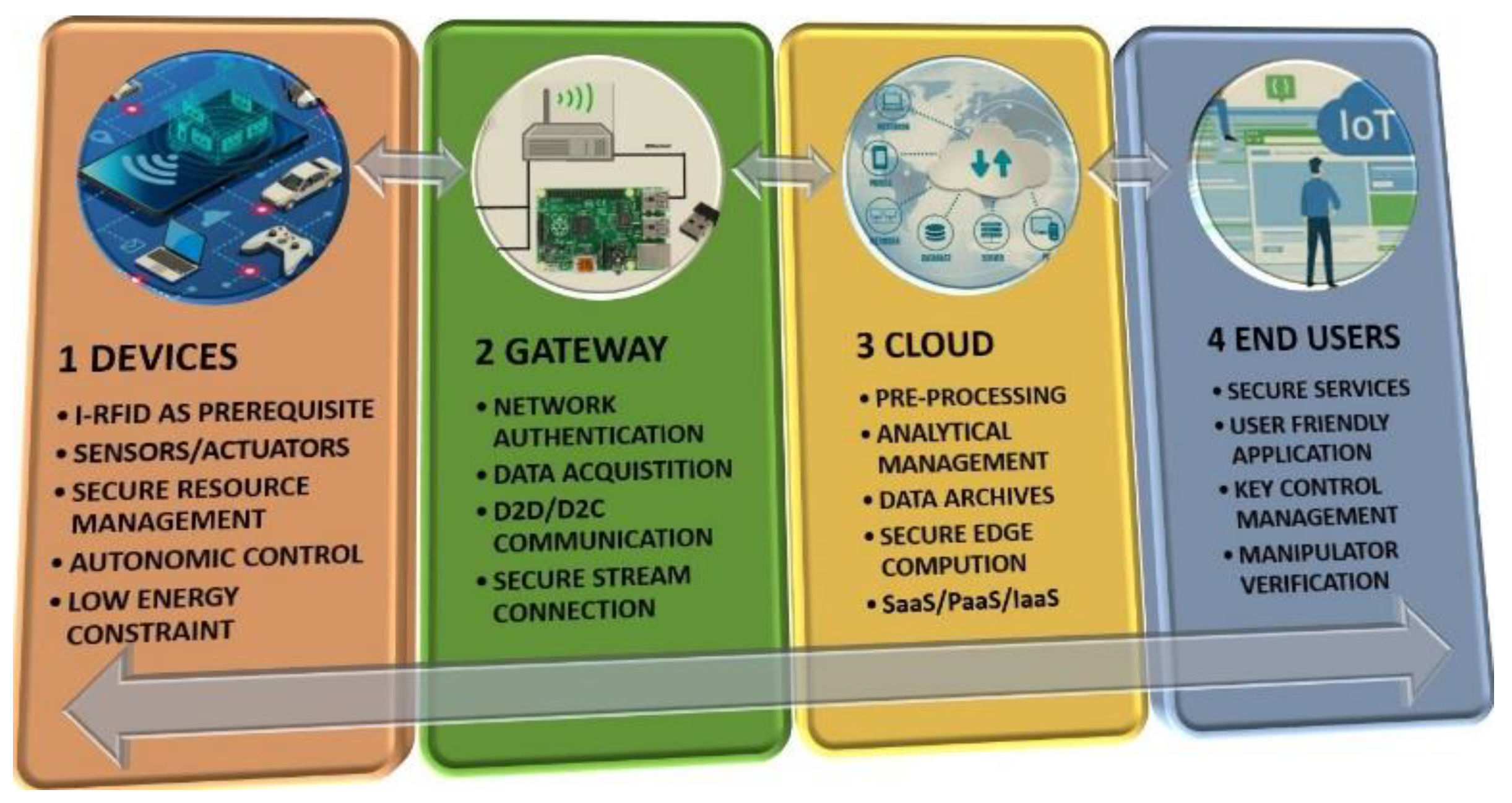
1. Introduction
Related Research Work
- Meandering angle formulation [27] for the MAT process, in order to minimize the antenna size and enhance the realized gain of the UHF RFID tag;
- The antenna’s inductive behavior is guaranteed through the introduction of capacitive end tip-loading [16];
- A dielectric effect is achieved w.r.t. the atmospheric humidity level;
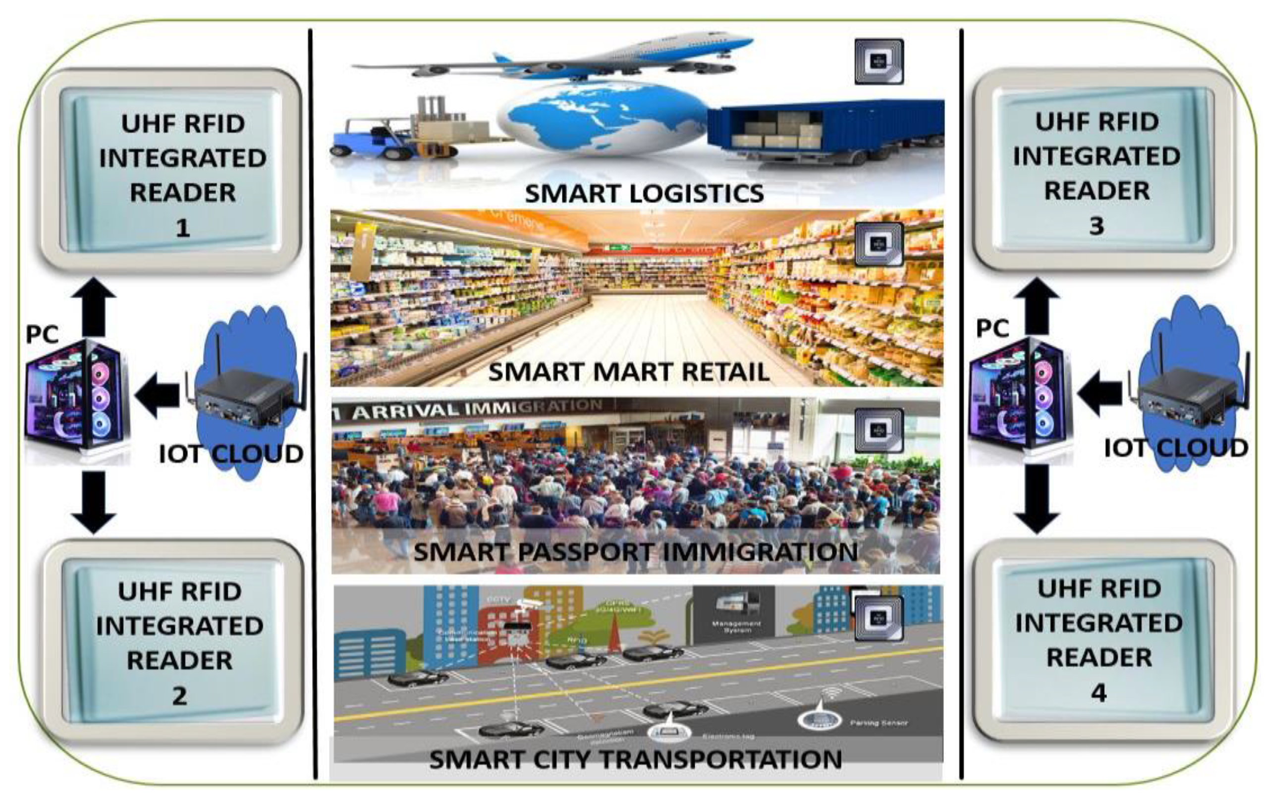
- We detail the indoor and outdoor I-RFID working mechanisms with the UHF RFID integrated reader (SL130) [30] for IoT smart X environments; and
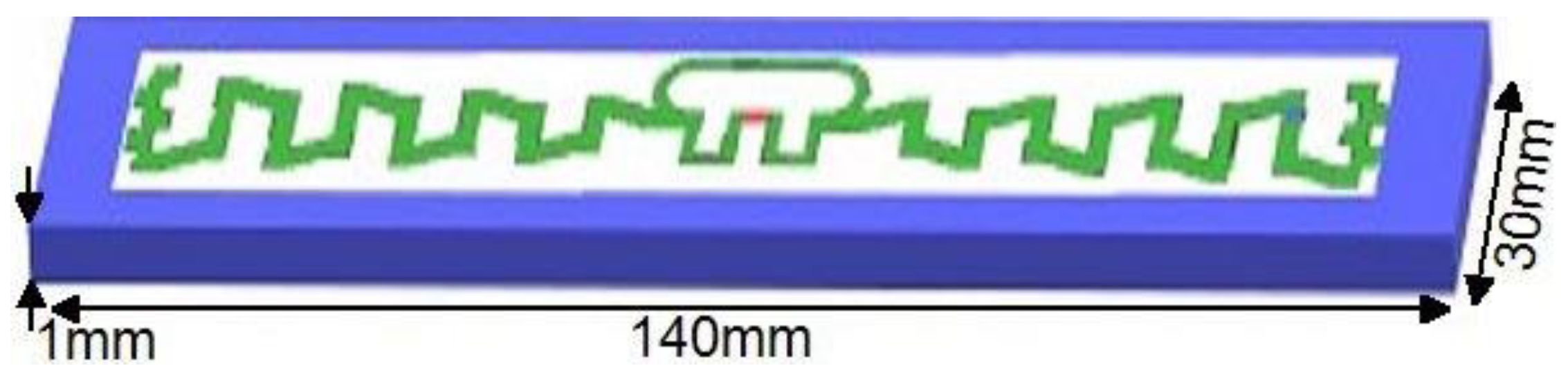
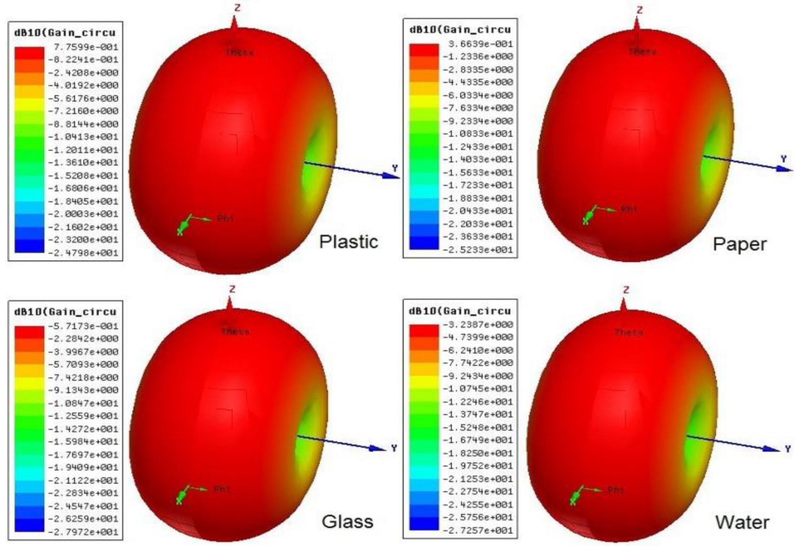
- We demonstrate the tags integrability with mounting platforms (plastic, paper, and glass) [31] to enable massive IoT devices in 5G systems.
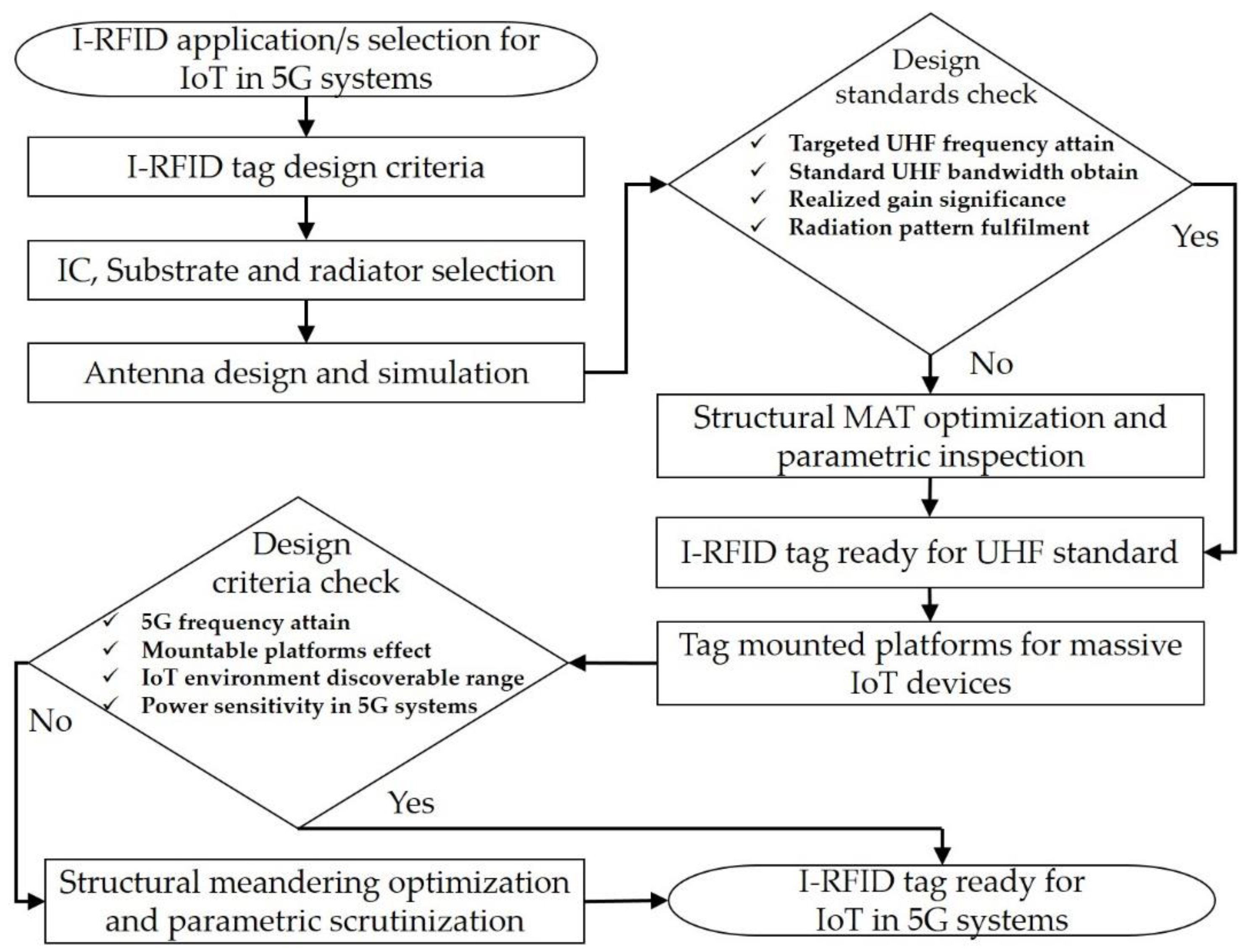
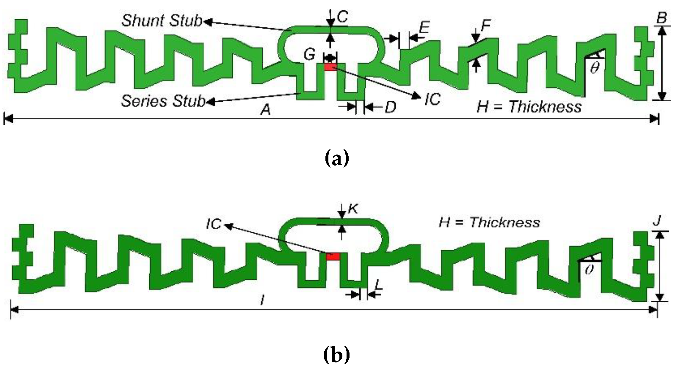
2. I-RFID Tag Antenna Design and Simulation
2.1. Meandering of Dipole
2.2. Meandering Angle Creation for Meandering Angle Technique (MAT)
2.3. Impedance Matching Network
2.4. Capacitive Antenna-End Tip-Loading
3. Results and Discussions
- Dipole meandering with MAT (Section 2.1 and Section 2.2);
- Perfect impedance matching (PIM) with the series and shunt stub technique (Section 2.3); and
- Antenna inductive behavior with capacitive end tip-loading (Section 2.4).
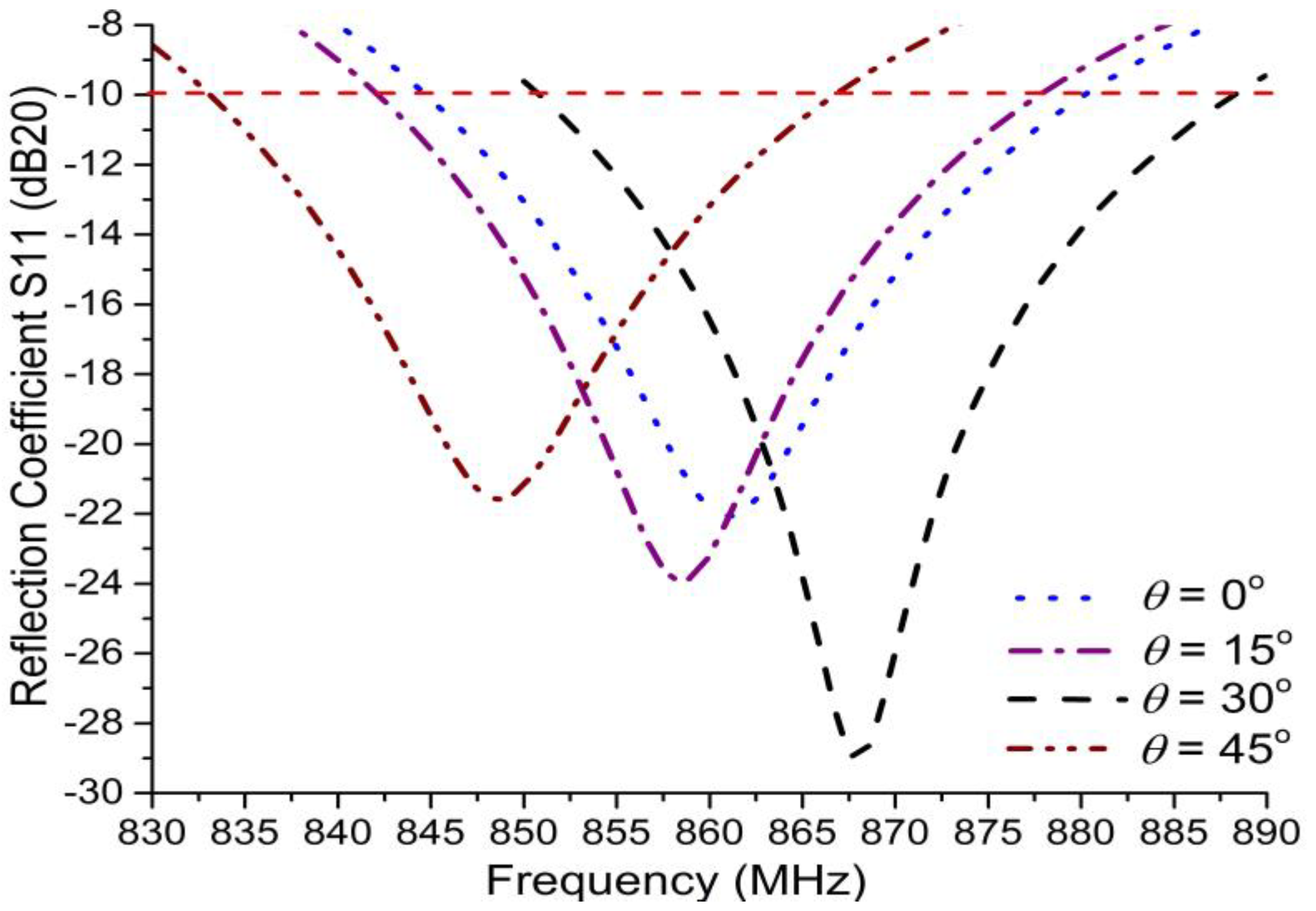
3.1. Meandering Angle Characteristics
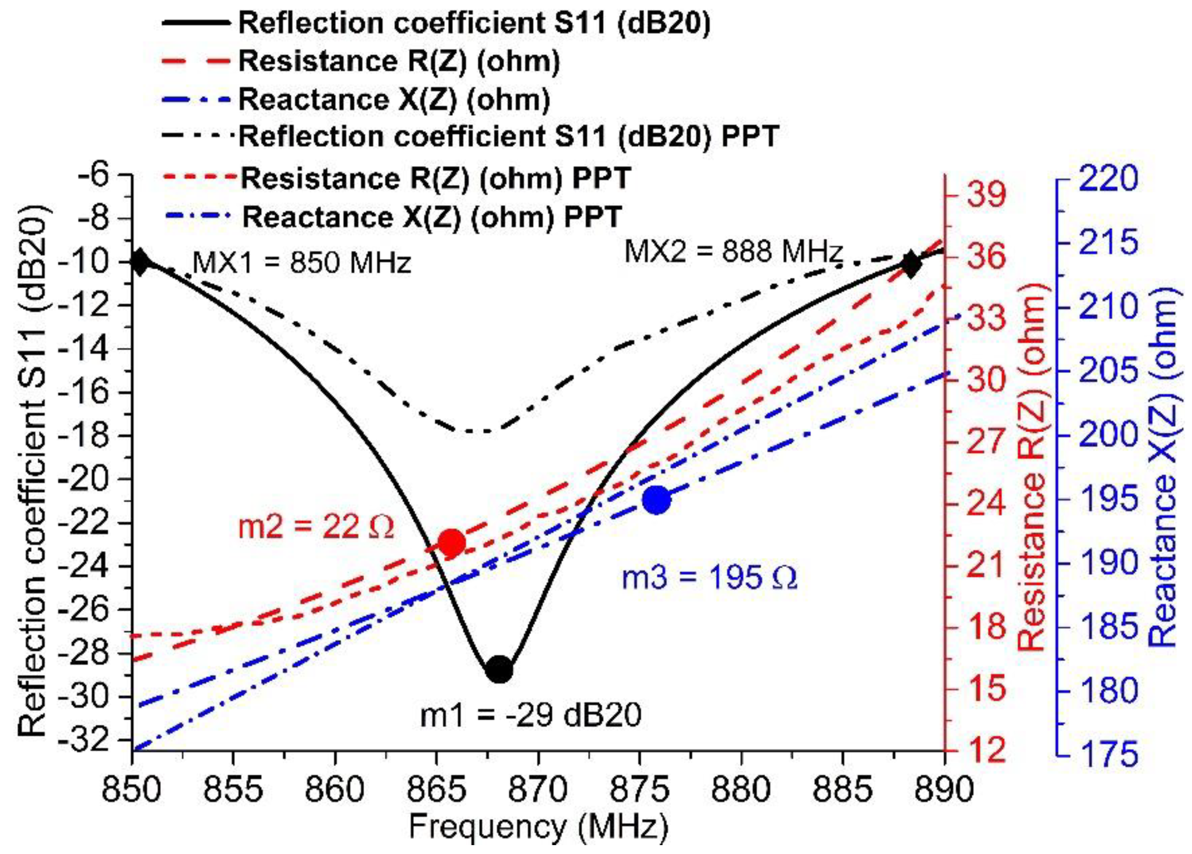
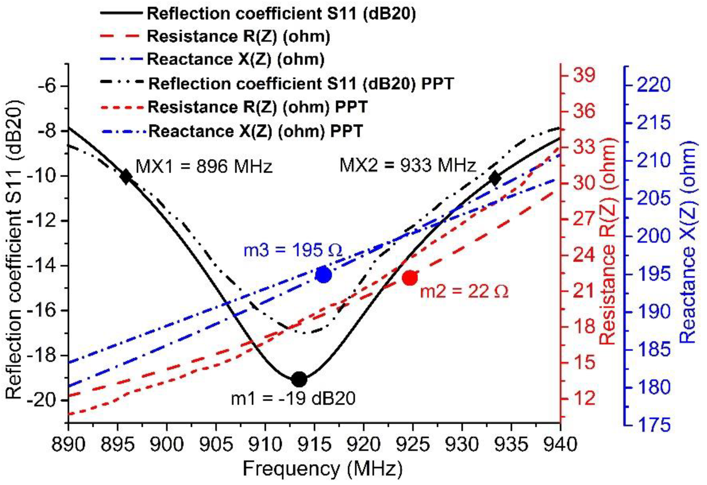
3.2. Series and Shunt Stubs Impedance Matching
3.3. Capacitive End Tip-Loading Bandwidth Effect
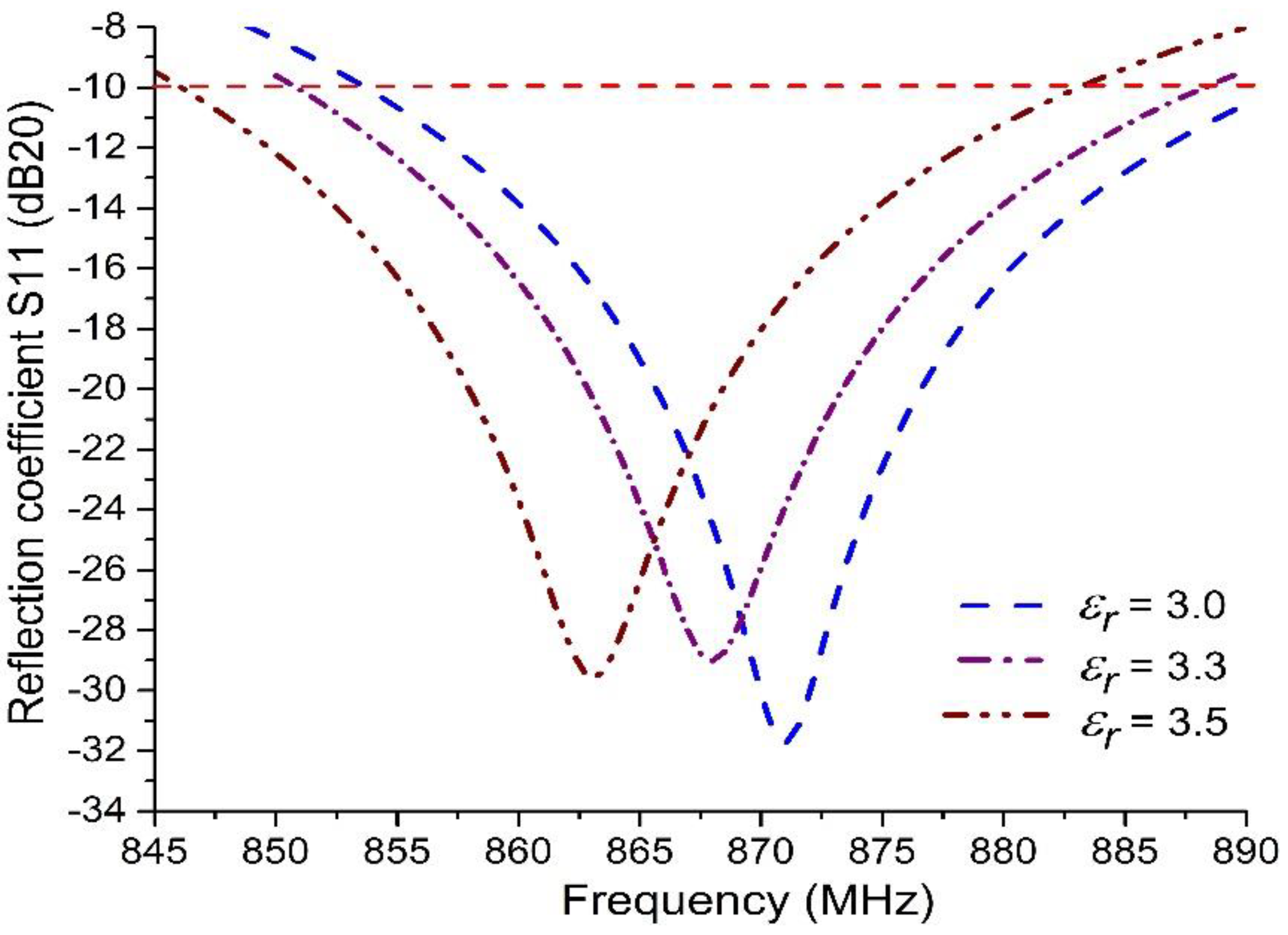
3.4. Dielectric Effect w.r.t. Atmospheric Humidity Level
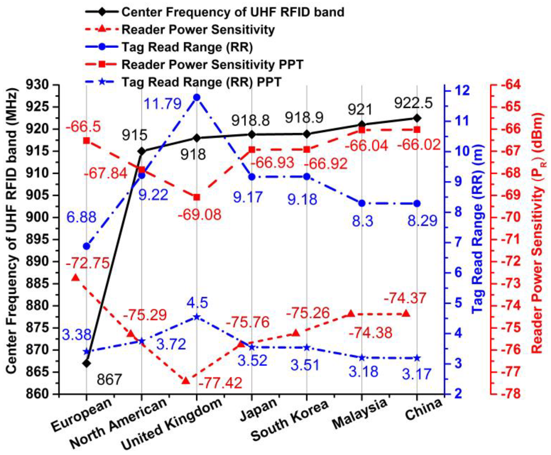
3.5. Tag Read Range (RR) w.r.t. Reader’s EIRP
3.6. Reader Power Sensitivity (PR)
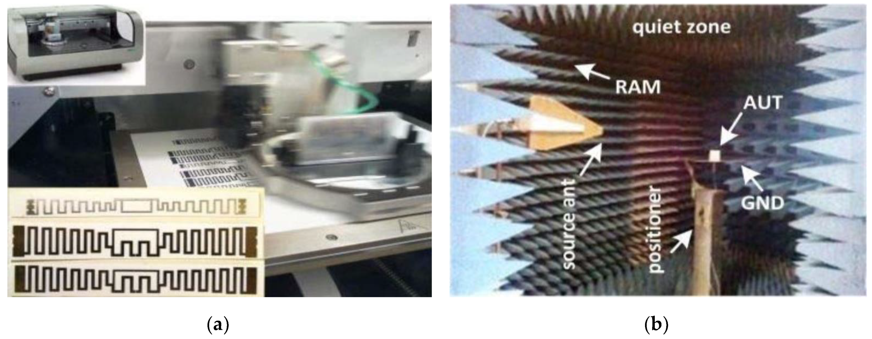
3.7. Experiment and Printing Setup
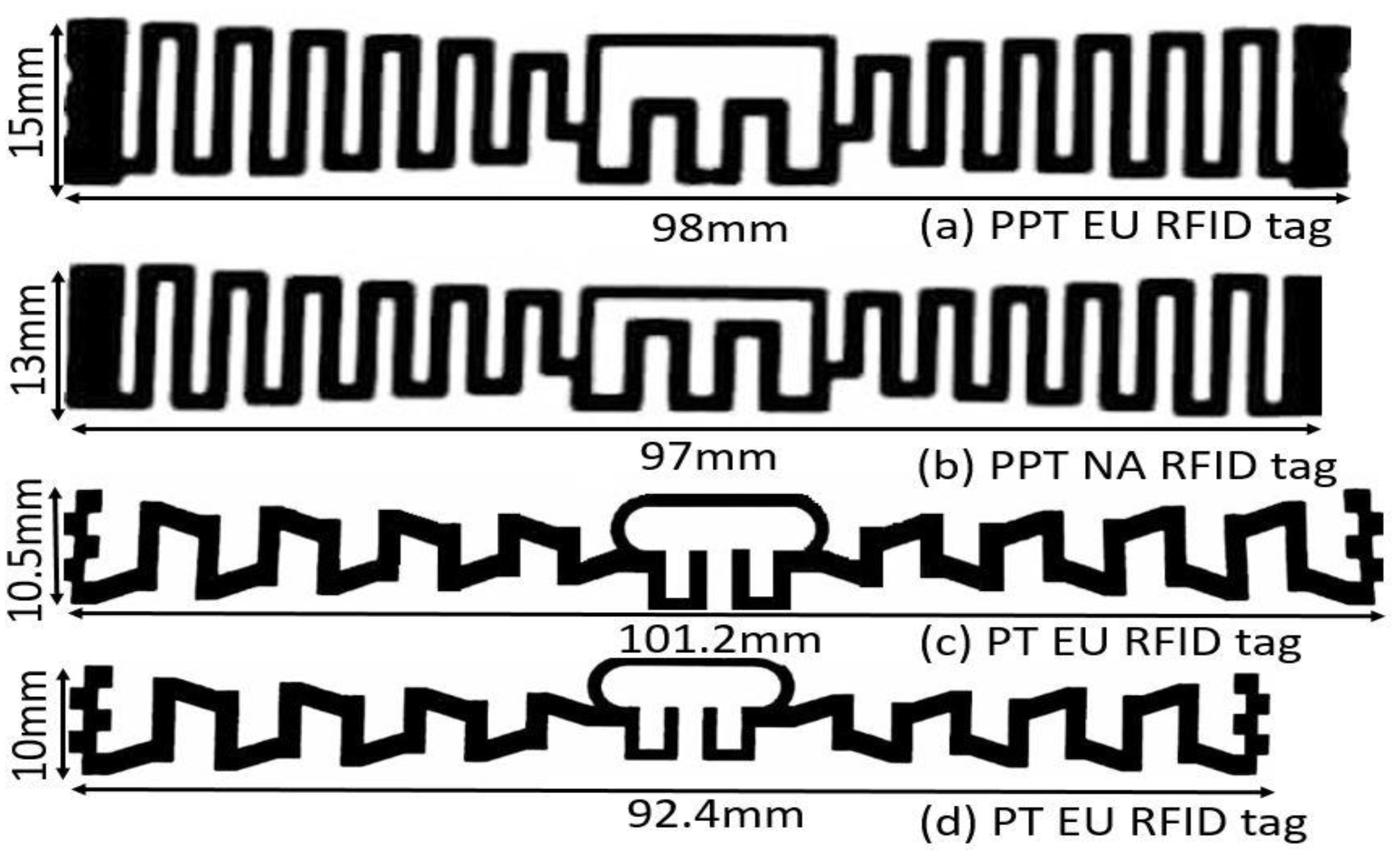
3.8. Comparison between Proposed Tags (PT) and Previous Published Tags (PPT)
3.9. I-RFID Indoor and Outdoor Work Mechanism for IoT in Smart X Environments
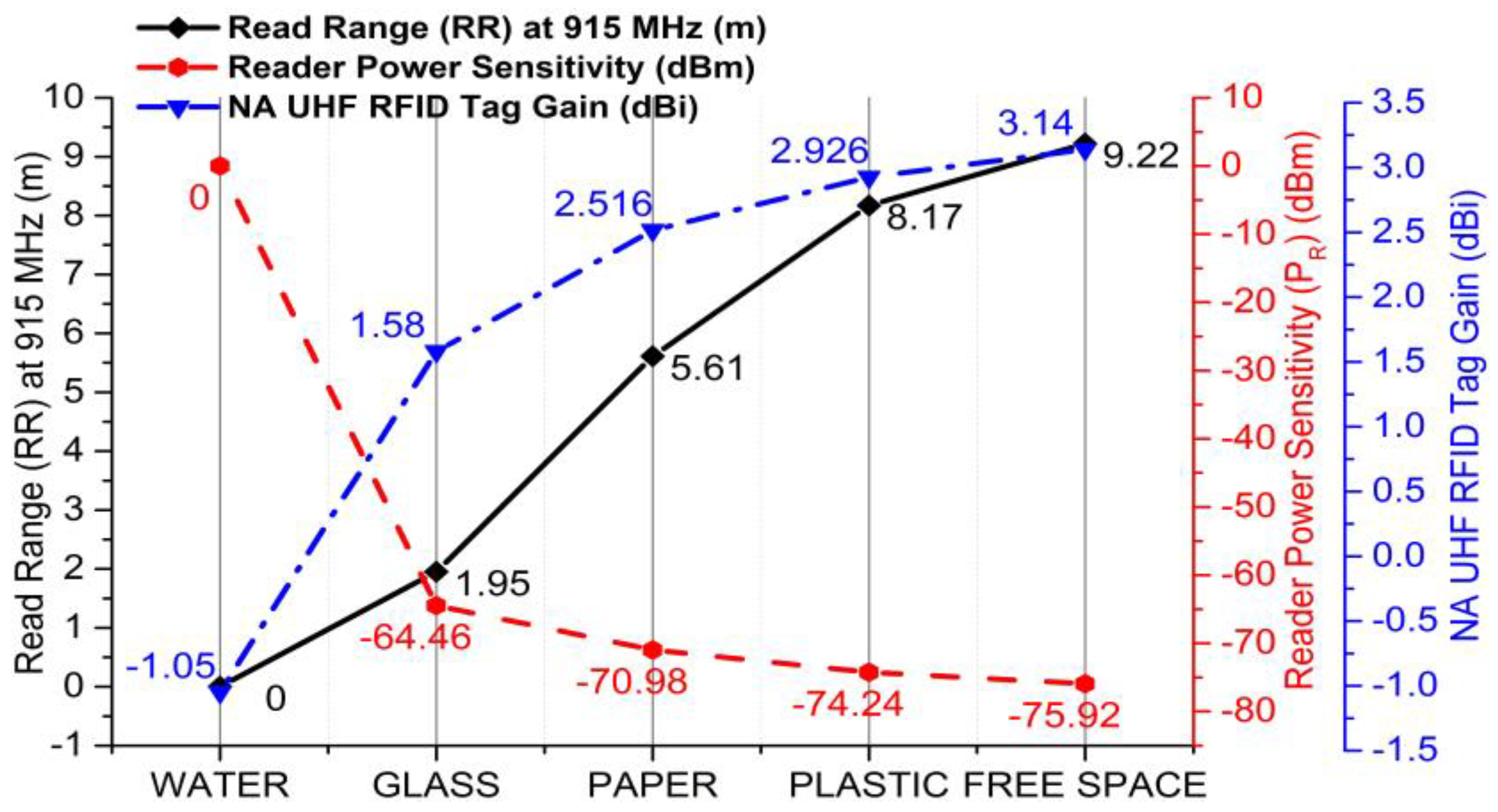
3.10. Tag Performance on Mounting Platforms
4. Conclusions
Author Contributions
Funding
Conflicts of Interest
References
- Tarricone, L.; Grosinger, J. Augmented RFID Technologies for the Internet of Things and Beyond; Multidisciplinary Digital Publishing Institute: Basel, Switzerland, 2020. [Google Scholar]
- Zhang, H.; Zhang, Z.; Zhang, L.; Yang, Y.; Kang, Q.; Sun, D. Object tracking for a smart city using IoT and edge computing. Sensors 2019, 19, 1987. [Google Scholar] [CrossRef] [PubMed]
- Lu, Y.; Da Xu, L. Internet of Things (IoT) cybersecurity research: A review of current research topics. IEEE Internet Things J. 2018, 6, 2103–2115. [Google Scholar] [CrossRef]
- Da Xu, L.; He, W.; Li, S. Internet of things in industries: A survey. IEEE Trans. Ind. Inform. 2014, 10, 2233–2243. [Google Scholar]
- Cmiljanic, N.; Landaluce, H.; Perallos, A. A comparison of RFID anti-collision protocols for tag identification. Appl. Sci. 2018, 8, 1282. [Google Scholar] [CrossRef]
- Hussain, T.; Muhammad, K.; Del Ser, J.; Baik, S.W.; de Albuquerque, V.H.C. Intelligent Embedded Vision for Summarization of Multi-View Videos in IIoT. IEEE Trans. Ind. Inform. 2019, 16, 2592–2602. [Google Scholar] [CrossRef]
- Hussain, T.; Muhammad, K.; Khan, S.; Ullah, A.; Lee, M.Y.; Baik, S.W. Intelligent Baby Behavior Monitoring using Embedded Vision in IoT for Smart Healthcare Centers. J. Artif. Intell. Syst. 2019, 1, 2019. [Google Scholar] [CrossRef]
- Tan, P.; Wu, H.; Li, P.; Xu, H. Teaching management system with applications of RFID and IoT technology. Educ. Sci. 2018, 8, 26. [Google Scholar] [CrossRef]
- Trinh, L.H.; Le, T.N.; Staraj, R.; Ferrero, F.; Lizzi, L. A pattern-reconfigurable slot antenna for IoT network concentrators. Electronics 2017, 6, 105. [Google Scholar] [CrossRef]
- Finkenzeller, K. RFID Handbook: Fundamentals and Applications in Contactless Smart Cards, Radio Frequency Identification and Near-Field Communication; John Wiley & Sons: Hoboken, NJ, USA, 2010. [Google Scholar]
- Loss, C.; Gonçalves, R.; Lopes, C.; Pinho, P.; Salvado, R. Smart coat with a fully-embedded textile antenna for IoT applications. Sensors 2016, 16, 938. [Google Scholar] [CrossRef]
- Gómez, M.E.D.C.; Álvarez, H.F.; Valcarce, B.P.; González, C.G.; Olenick, J.; Las-Heras, F. Zirconia-Based Ultra-Thin Compact Flexible CPW-Fed Slot Antenna for IoT. Sensors 2019, 19, 3134. [Google Scholar] [CrossRef]
- Dobkin, D.M. The Rf in RFID: Uhf RFID in Practice; Newnes: Waltham, MA, USA, 2012. [Google Scholar]
- Luo, X.; Chen, D.; Wang, Y.; Xie, P. A type-aware approach to message clustering for protocol reverse engineering. Sensors 2019, 19, 716. [Google Scholar] [CrossRef] [PubMed]
- Tariq, N.; Asim, M.; Al-Obeidat, F.; Farooqi, M.Z.; Baker, T.; Hammoudeh, M.; Ghafir, I. The security of big data in fog-enabled IoT applications including blockchain: A survey. Sensors 2019, 19, 1788. [Google Scholar] [CrossRef] [PubMed]
- Amin, Y.; Chen, Q.; Tenhunen, H.; Zheng, L.R. Evolutionary versatile printable RFID antennas for “Green” electronics. J. Electromagn. Waves Appl. 2012, 26, 264–273. [Google Scholar] [CrossRef]
- Riaz, M.; Rymar, G.; Ghavami, M.; Dudley, S. A novel design of UHF RFID passive tag antenna targeting smart cards limited area. In Proceedings of the 2018 IEEE International Conference on Consumer Electronics (ICCE), Las Vegas, NV, USA, 12–14 January 2018; pp. 1–4. [Google Scholar]
- Byondi, F.K.; Sul, C.; Chung, Y. Super Long Range Small Empty Cavity UHF RFID Tag Antenna Design for a Metal Cart. In Proceedings of the 2018 IEEE Region Ten Symposium (Tensymp), Sydney, NSW, Australia, 4–6 July 2018; pp. 145–148. [Google Scholar]
- Jebbawi, K.; Egels, M.; Pannier, P.J.M.; Letters, O.T. A novel compact circularly polarized tag antenna with differential-RFIC for EU UHF RFID applications. Microw. Opt. Technol. Lett. 2020, 62, 1621–1627. [Google Scholar] [CrossRef]
- Nadzir, N.M.; Rahim, M.K.A.; Zubir, F.; Samsuri, N.A.; Ayop, O.; Majid, H. Passive UHF RFID tag Antenna using Polycarbonate and PDMS Material. In Proceedings of the 2018 International Symposium on Antennas and Propagation (ISAP), Busan, Korea, 23–26 October 2018; pp. 1–2. [Google Scholar]
- Bakkali, M.E.; Mrabet, O.E.; Khamlichi, M.E.; Khalladi, M.; Ennasar, M.A. Single-Layer UHF RFID Tag Antenna with Multifunctional Characteristics. In Proceedings of the 2018 6th International Conference on Multimedia Computing and Systems (ICMCS), Rabat, Morocco, 10–12 May 2018; pp. 1–3. [Google Scholar]
- Bouazza, H.; Lazaro, A.; Bouya, M.; Hadjoudja, A. Parameters Affecting UHF RFID Tag Performances. In Proceedings of the 2019 IEEE International Conference on RFID Technology and Applications (RFID-TA), Pisa, Italy, 25–27 September 2019; pp. 55–57. [Google Scholar]
- Franchina, V.; Ria, A.; Michel, A.; Bruschi, P.; Nepa, P.; Salvatore, A. A Compact UHF RFID Ceramic Tag for High-Temperature Applications. In Proceedings of the 2019 IEEE International Conference on RFID Technology and Applications (RFID-TA), Pisa, Italy, 25–27 September 2019; pp. 480–483. [Google Scholar]
- Ramos, A.; Varum, T.; Matos, J.N. Compact multilayer Yagi-Uda based antenna for IoT/5G sensors. Sensors 2018, 18, 2914. [Google Scholar] [CrossRef]
- El Bakkali, M.; Gaba, G.S.; Tubbal, F.; Kansal, L.; El Idrissi, N.E.A. Analysis and Optimization of a Very Compact MPA with Parasitic Elements for Inter-swarm of CubeSats Communications. In Proceedings of the International Conference on Advanced Informatics for Computing Research, Shimla, India, 15–16 June 2019; Springer: Berlin/Heidelberg, Germany, 2019; pp. 128–143. [Google Scholar]
- Byondi, F.K.; Chung, Y. Longest-Range UHF RFID Sensor Tag Antenna for IoT Applied for Metal and Non-Metal Objects. Sensors 2019, 19, 5460. [Google Scholar] [CrossRef]
- Strang, G. Calculus, 2nd ed.; Wellesley Cambridge Press: Cambridge, UK, 1991. [Google Scholar]
- NXP Semiconductors. Product Data Sheet of SL3ICS1002/1202, UCODE G2XM and G2XL. Available online: https://www.nxp.com/docs/en/data-sheet/SL3ICS1002_1202.pdf (accessed on 7 July 2020).
- Balanis, C.A. Antenna Theory: Analysis and Design; John Wiley & Sons: Hoboken, NJ, USA, 2016. [Google Scholar]
- Stronglink-rfid. Product Data Sheet of UHF Integrated Reader SL130. Available online: http://www.stronglink-rfid.com/download/SL130_Product_information_guidance.pdf (accessed on 7 July 2020).
- Aslam, B.; Kashif, M.; Azam, M.A.; Amin, Y.; Loo, J.; Tenhunen, H.J.E. A low profile miniature RFID tag antenna dedicated to IoT applications. Electromagnetics 2019, 39, 393–406. [Google Scholar] [CrossRef]
- International Telecommunication Union (ITU). Technical Characteristics, Standards, and Frequency Bands of Operation for Radio-Frequency Identification (RFID) and Potential Harmonization Opportunities; ‘ITU-R SM.2255-0’; Geneva, Switzerland, 2015; Available online: https://www.itu.int/dms_pub/itu-r/opb/rep/R-REP-SM.2255-2012-PDF-E.pdf (accessed on 8 July 2020).
- Hu, T.; Liu, C.; Wang, Z. Design and analysis of UHF tag antenna structure. In Proceedings of the 2011 China-Japan Joint Microwave Conference, Hangzhou, China, 20–22 April 2011; Institute of Electrical and Electronics Engineers (IEEE): New York, NY, USA, 2011; pp. 1–4. [Google Scholar]
- Abdulhadi, A.E.; Abhari, R. Dual printed meander monopole antennas for passive UHF RFID tags. In Proceedings of the 2011 IEEE International Symposium on Antennas and Propagation (APSURSI), Washington, DC, USA, 3–8 July 2011; Institute of Electrical and Electronics Engineers (IEEE): New York, NY, USA, 2011; pp. 988–991. [Google Scholar]
- Mirza, H.; Elahi, M.F. A UHF-RFID tag antenna for commercial applications. In Proceedings of the 2008 International Conference on Electrical and Computer Engineering, Phuket, Thailand, 20–22 December 2008; Institute of Electrical and Electronics Engineers (IEEE): New York, NY, USA, 2008; pp. 764–767. [Google Scholar]
- Son, H.-W.; Jeong, S.-H. Wideband RFID Tag Antenna for Metallic Surfaces Using Proximity-Coupled Feed. IEEE Antennas Wirel. Propag. Lett. 2011, 10, 377–380. [Google Scholar] [CrossRef]
- Faudzi, N.M.; Ali, M.T.; Ismail, I.; Jumaat, H.; Sukaimi, N.H.M. A compact dipole UHF-RFID tag antenna. In Proceedings of the 2013 IEEE International RF and Microwave Conference (RFM), Penang, Malaysia, 9–11 December 2013; pp. 314–317. [Google Scholar]
- Lin, Y.-S.; Liu, H.-W.; Wu, K.-H.; Yang, C.-F. Communications. A Miniature Chip Antenna Design for a Passive UHF RFID Tag to Be Built in a Portable Device. In Proceedings of the Electromagnetics Research Symposium, Beijing, China, 23–27 March 2009; p. 572. [Google Scholar]
- Rao, K.S.; Nikitin, P.V.; Lam, S.F. Antenna design for UHF RFID tags: A review and a practical application. IEEE Trans. Antennas Propag. 2005, 53, 3870–3876. [Google Scholar] [CrossRef]
- Virtanen, J.; Virkki, J.; Ukkonen, L.; Sydänheimo, L. Inkjet-Printed UHF RFID Tags on Renewable Materials. Adv. Internet Things 2012, 2, 79–85. [Google Scholar] [CrossRef]
- Lee, Y.-H.; Lim, E.-H.; Bong, F.-L.; Chung, B.-K. Compact Folded C-Shaped Antenna for Metal-Mountable UHF RFID Applications. IEEE Trans. Antennas Propag. 2018, 67, 765–773. [Google Scholar] [CrossRef]
- Ennajih, A.; Nasiri, B.; Zbitou, J.; Errkik, A.; Latrach, M. A Novel Design of Miniaturized Tag Antenna Loaded Metamaterial Spiral Split Ring Resonator. Int. J. Intell. Eng. Syst. 2019, 12, 12–21. [Google Scholar] [CrossRef]
- Zhang, J.; Long, Y. A Novel Metal-Mountable Electrically Small Antenna for RFID Tag Applications With Practical Guidelines for the Antenna Design. IEEE Trans. Antennas Propag. 2014, 62, 5820–5829. [Google Scholar] [CrossRef]
- Jiang, Y.; Leng, T.; Fang, Y.; Hu, Z.; Xu, L. Machine Embroidered Wearable e-textile Wideband UHF RFID Tag Antenna. In Proceedings of the 2019 IEEE International Symposium on Antennas and Propagation and USNC-URSI Radio Science Meeting, Atlanta, GA, USA, 7–12 July 2019; pp. 643–644. [Google Scholar]


| Values | A | B | C | D | E | F | G |
| (mm) | 101.2 | 10.5 | 1 | 1.2 | 1.6 | 3 | 2 |
| Values | H | I | J | K | L | θ | |
| (mm) | 0.015 | 92.4 | 10 | 1 | 1 | 30° |
| Angle (Degree) | EU/NA UHF Band | S11 (dB) | Bandwidth (BW) (MHz) at −10 dB | Compact Size (cm2) | Gain (dBi) |
|---|---|---|---|---|---|
| θ = 0° | EU | −22 | 36 | 10.12 cm × 1.22 cm | 2.38 |
| θ = 15° | EU | −23.9 | 35 | 10.12 cm × 1.10 cm | 2.28 |
| θ = 30° | EU | −29 | 37 | 10.12 cm × 1.05 cm | 2.75 |
| θ = 45° | EU | −21 | 33 | 10.12 cm × 1.06 cm | 1.75 |
| θ = 30° | NA | −18.5 | 37 | 9.24 cm × 1.0 cm | 3.14 |
| Name | Shape | Area | Bandwidth at (S11 = −10 dB) | Bandwidth at (S11 = −15 dB) |
|---|---|---|---|---|
| Rectangular |  | 30 mm2 | 27 MHz | n/a |
| Small-Square |  | 20 mm2 | 37 MHz | 20 MHz |
| Ref. | EU/ NA | Tag Dimension (mm3) | Gain (dBi) | Bandwidth (BW) (MHz) at −10 dB | Read Range (RR) (m) |
|---|---|---|---|---|---|
| [16] | EU | 98 × 15 × 0.39 | 2.1 | 51 | 3.38 |
| NA | 97 × 13 × 0.39 | 3.72 | |||
| [17] | EU | 49.14 × 17.9 × 0.5 | 1.7 | 8 | 5.95 |
| [18] | NA | 140 × 60 × 10 | n/a | 0 | 7.5 |
| [20] | NA | 93 × 23 × 8 | 1.5 | 60 | 5 |
| [21] | EU | 92 × 33.54 × 1.38 | 1 | 22 | 4 |
| NA | 87.8 × 31 × 1.31 | 1.5 | 28 | 5 | |
| [22] | EU | 85 × 40 × 3.2 | n/a | 8 | ~7.5 (−15 dBm) |
| [23] | EU | 23 × 23 × 1 | n/a | n/a | 1 |
| Ours | EU | 101.2 × 10.5 × 0.39 | 2.75 | 37 | 6.88 |
| NA | 92.4 × 10 × 0.39 | 3.1 | 37 | 9.22 |
| Platforms | Permittivity (εr) | Tangent Loss (δ) |
|---|---|---|
| Plastic | 3 | 3 |
| Paper | 3.2 | 0.07 |
| Glass | 4.82 | 0.0054 |
| Water | 77.3 | 0.147 |
| Platforms | fc Variation | Bandwidth Variation | Circuit Gain (dBi) | Read Range (m) | Sensitivity (dBm) |
|---|---|---|---|---|---|
| Free Space | 0 | 0 | 3.14 | 9.22 | −75.92 |
| Plastic | −45 | 0 | 2.926 | 8.17 | −74.24 |
| Paper | −47 | 0 | 2.516 | 5.61 | −70.98 |
| Glass | −78 | −3 | 1.58 | 1.95 | −64.46 |
| Water | +80 | −7 | −1.05 | 0 | 0 |
© 2020 by the authors. Licensee MDPI, Basel, Switzerland. This article is an open access article distributed under the terms and conditions of the Creative Commons Attribution (CC BY) license (http://creativecommons.org/licenses/by/4.0/).
Share and Cite
Hussain, M.; Amin, Y.; Lee, K.-G. A Compact and Flexible UHF RFID Tag Antenna for Massive IoT Devices in 5G System. Sensors 2020, 20, 5713. https://doi.org/10.3390/s20195713
Hussain M, Amin Y, Lee K-G. A Compact and Flexible UHF RFID Tag Antenna for Massive IoT Devices in 5G System. Sensors. 2020; 20(19):5713. https://doi.org/10.3390/s20195713
Chicago/Turabian StyleHussain, Muhammad, Yasar Amin, and Kyung-Geun Lee. 2020. "A Compact and Flexible UHF RFID Tag Antenna for Massive IoT Devices in 5G System" Sensors 20, no. 19: 5713. https://doi.org/10.3390/s20195713
APA StyleHussain, M., Amin, Y., & Lee, K.-G. (2020). A Compact and Flexible UHF RFID Tag Antenna for Massive IoT Devices in 5G System. Sensors, 20(19), 5713. https://doi.org/10.3390/s20195713