Architecting and Deploying IoT Smart Applications: A Performance–Oriented Approach

 , , and
Abstract
1. Introduction
2. Background and Related Work
2.1. IoT Architectures and Platforms
2.2. LPWAN Technologies for IoT
2.3. Fog and Mist Computing for IoT
2.4. IoT Smart Applications
2.5. Performance and Scalability of IoT Systems
3. Architecting and Deploying IoT Smart Applications
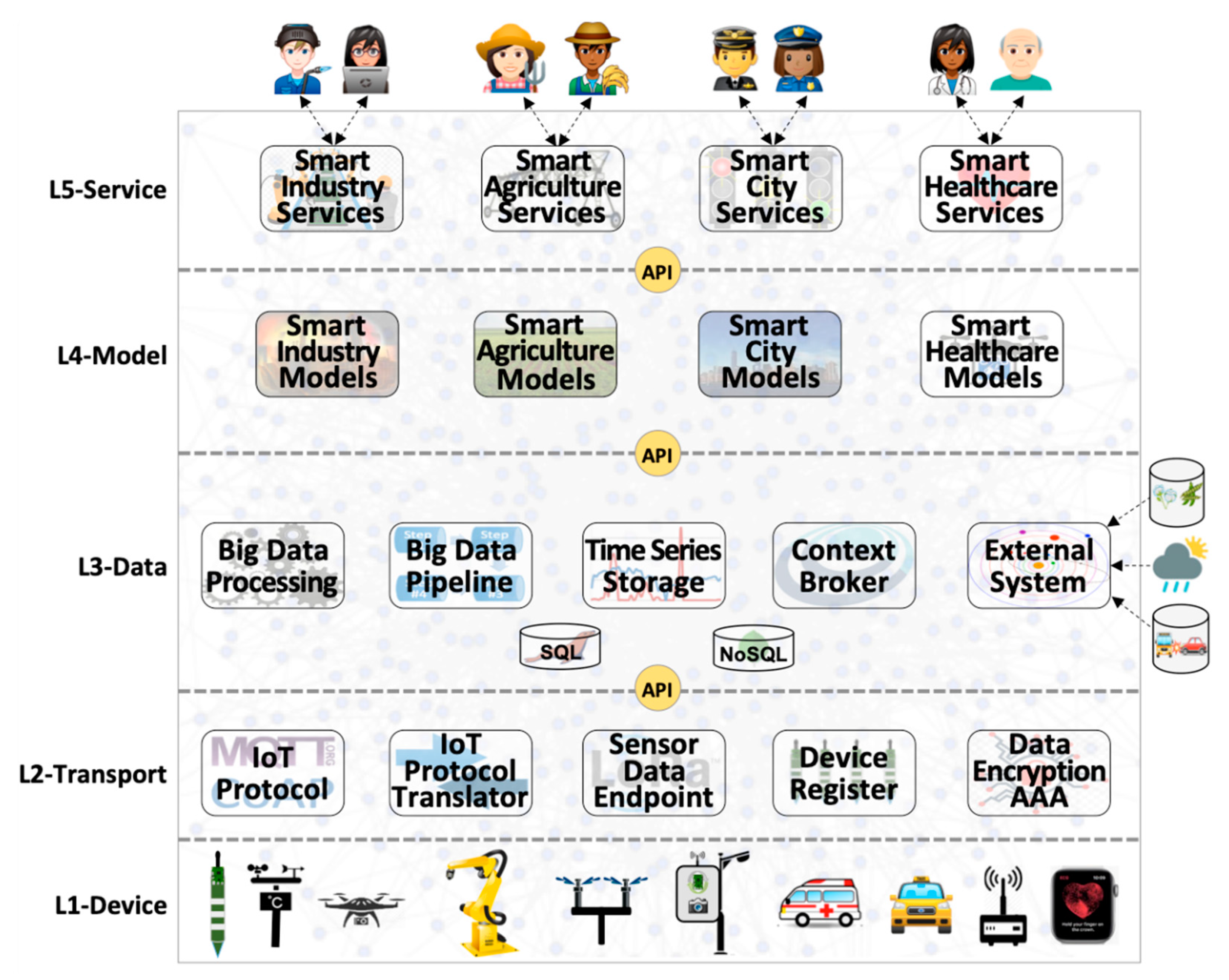
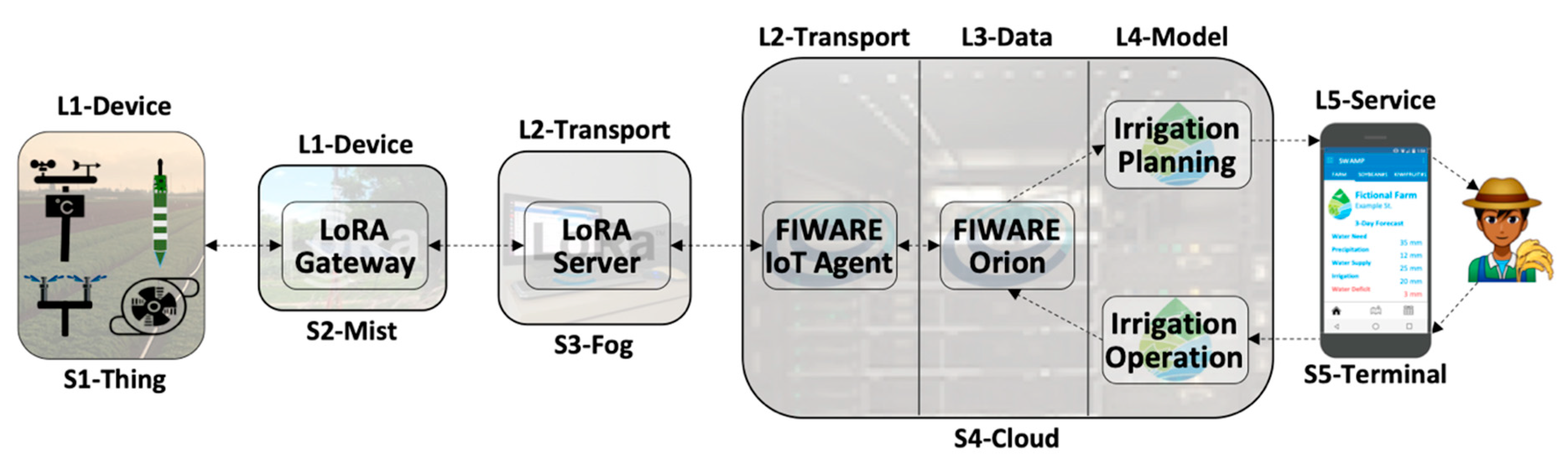
- Layer 1 (L1-Device): Sensors, actuators, and communication technologies—both wired and wireless—make up the lowest layer of the IoT architecture. Devices are sensors and actuators that represent IoT things. Figure 1 depicts some examples of Layer 1 components, such as industrial robots, that have many sensors to track their actions, and actuators to control engines that make them move according to different degrees of freedom, both exchanging messages with a smart industry application via wired and wireless communication technologies.
- Layer 2 (L2-Transport): Collecting data from sensors, making it available to data management functions, receiving commands from application models, and sending them to actuators require a good deal of intermediate components to make it happen. Figure 1 depicts some examples of generic data transport functions for sensing and actuation purposes, such as: (a) IoT protocol (e.g., MQTT [50]) that sends data from IP speaking devices to place where they are transformed or filtered either by other components of this layer or by data management components; (b) IoT protocol translator (e.g., FIWARE IoT Agent) converts data from IoT protocol format (e.g., byte stream for MQTT) into its internal format within data management components (e.g., NGSI/JSON [29] for FIWARE) and vice-versa; (c) Sensor data endpoint (e.g., ChirpStack [34]) transports, unpacks and decodes data for specific IoT wireless communication technologies such as LPWAN [16]; (d) Device register deals with the myriad of connected devices; (e) Data encryption and Authentication, Authorization, and Accounting (AAA) is pervasively necessary for IoT communications and included in Layer 2. A general function of data security and network/service management are transversal functions, as all layers pervasively needed them (not represented in Figure 1, though).
- Layer 3 (L3-Data): Every stage of any end-to-end IoT data flow needs to deal with data in different ways, such as storing, retrieving, distributing, transforming, and filtering. Figure 1 depicts some examples of generic data management functions, such as: (a) Context broker (e.g., FIWARE Orion [51]) for context data distribution and related storage system; (b) Big data pipeline (e.g., Apache Kafka [52]) for raw data distribution and replication; (c) Big data processing (e.g., Apache Spark [53]) for processing large amounts of data; (d) Time series storage (e.g., CrateDB [54]) for historical data, and; (e) Interfacing with external systems, such as weather forecast services, online city traffic management services and databases.
- Layer 4 (L4-Model): Represent application-specific models for any type of processing over data collected from sensors and external systems, encompassing an assortment of algorithms, equations, methods and techniques that change the data into knowledge that is used by end-users to change the environment in a way that fits their best interests. For example, a smart irrigation application may use soil and weather data, as well as weather forecast information (external system), to feed physical and machine learning models to precisely compute when and how much crops should be irrigated [4].
- Layer 5 (L5-Service): Contains services that support the interfaces and the interaction with end-users of smart applications. This layer encompasses all services, applications, and graphical interfaces that provide visualization of sensor data, sensing and actuation infrastructures, analyses, choices, and decisions, as well as commands to change the state of the system. Figure 1 depicts four IoT verticals as examples of smart applications, namely smart agriculture, smart city, smart healthcare, and smart industry.
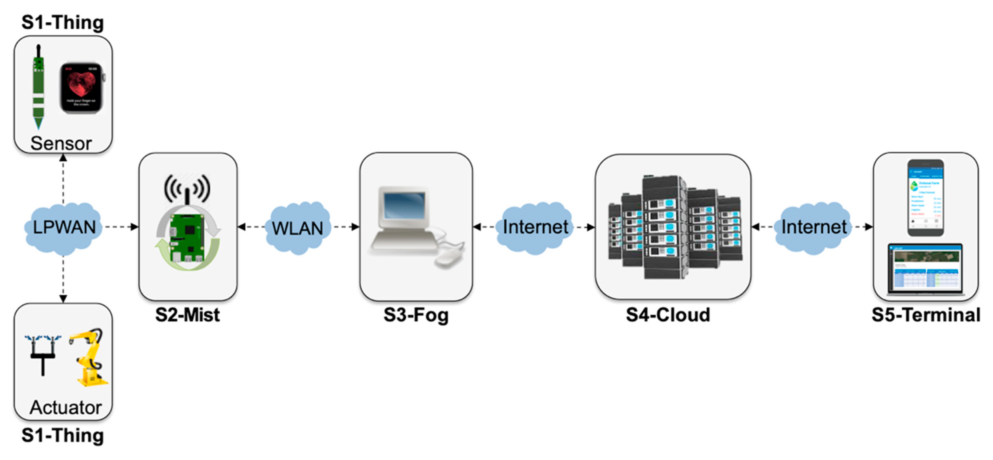
- S1-Thing: represents the stage implemented by hardware devices, i.e., sensors and actuators, which convert analog to digital signals and perform simple device-specific transformations, such as calibration.
- S2-Mist: mist nodes are installed in the field and play the role of radio gateways [55] in the context of LPWAN—or similar technologies—that support device data communication but also processing, such as data aggregation. Mist nodes are close to the devices they assist and typically have modest computing resources, similar to a Raspberry Pi.
- S3-Fog: fog nodes are installed in sheltered places with stable power supply and include equipment such as laptops, desktops, or small servers, which provide system reliability, robustness, resilience, and low latency for time-sensitive applications.
- S4-Cloud: public or private clouds host physical servers and virtual machines in a datacenter with plenty of resources. There is a noticeable increase in the processing power from S1-Thing to S4-Cloud
- S5-Terminal: the place where the end-user interacts with a smart application, connected to S4-Cloud, but also S3-Fog in some configurations.
4. Performance Analysis: Design and Methods
4.1. Design Decisions and Deployment Configurations
- Application independence: Layers L4-Model and L5-Application of IoTecture represent specific applications. This study addresses architectural components that comprise a common IoT platform, oblivious of smart application particularities. Thus, application-specific components are not included in our experiments. As applications must consume data managed by L3-Data, a simple Consumer component was added to represent L4-Model as a generic data sink. As a direct consequence of this choice, data flows only in one way, from sensors to the consumer located at the cloud. In other words, users are not involved, and therefore, L5-Service and T5-Terminal are outside of the scope of this work.
- Communication independence: in order to understand scalability limits, our study was performed in a lab testbed, wherein we can increase the workload by abstracting a large number of sensors using the SenSE sensor simulator [56] that generates data at different rates. Therefore, real IoT communication technologies-e.g., LPWAN-were not included in our experiments. Nevertheless, since LoRaWAN is currently a key LPWAN technology that needs a middleware component to work properly, a LoRaWAN server was included, as it belongs to L2-Transport playing the role of a sensor data endpoint. SenSE generates data emulating a LoRaWAN device, in a way that the server is unaware of not receiving data from real sensors. The configurations with ChirpStack are compared to configurations with a generic LPWAN technology where the sensor simulator generates data in a simple string-based protocol–e.g., Ultralight 2.0-and does not need to go through to the particularities of a specific LPWAN technology.
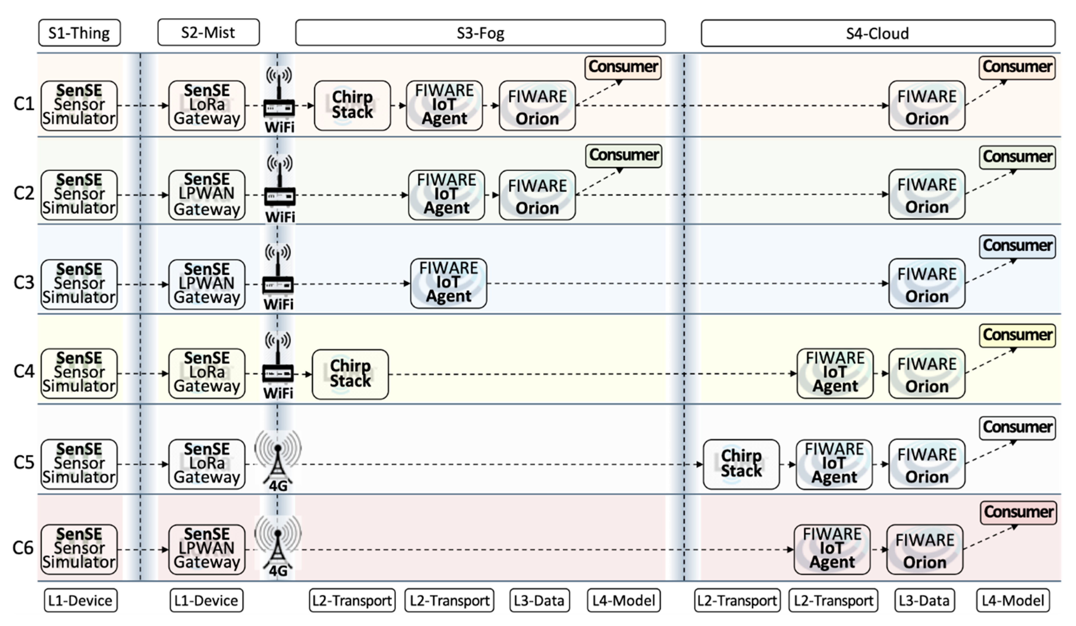
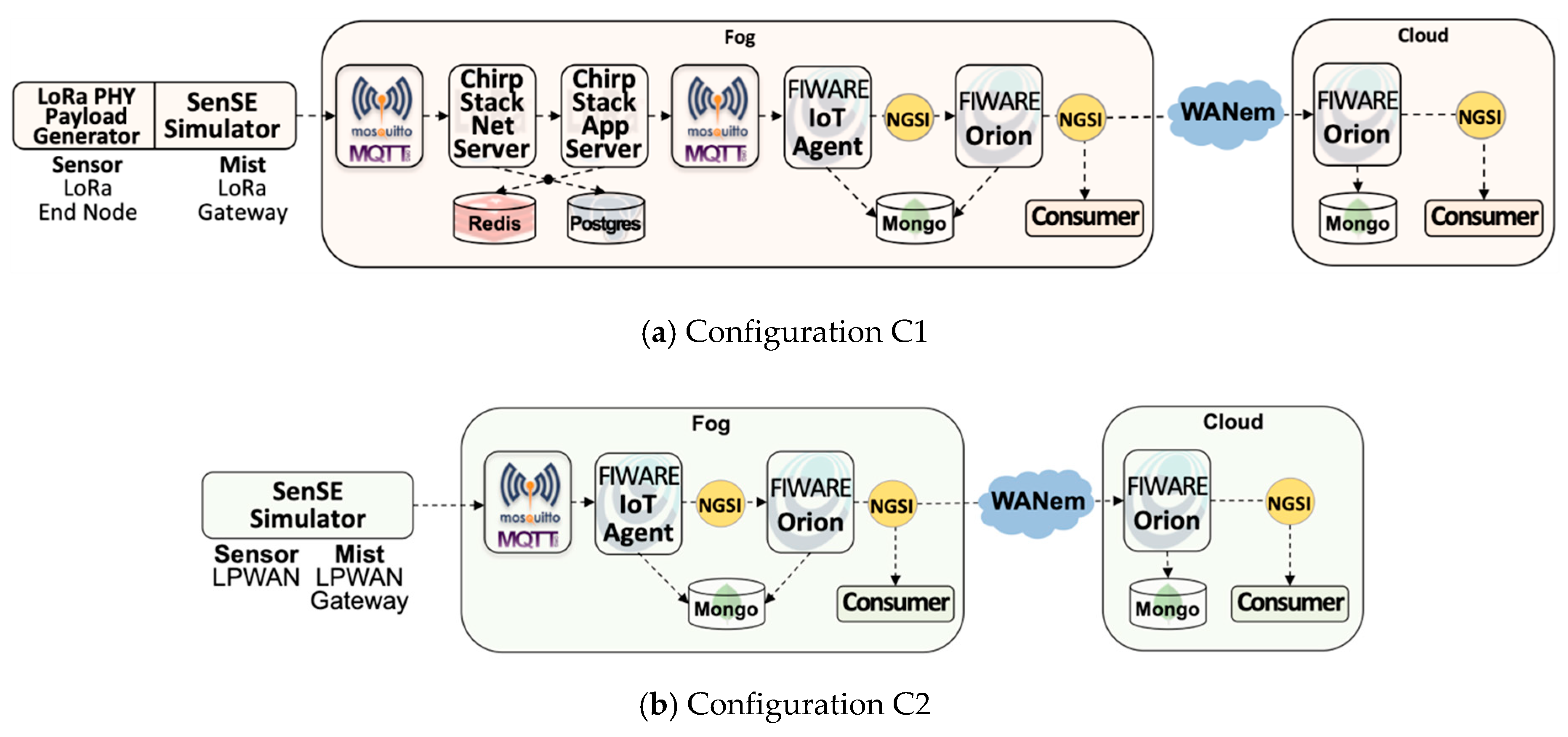
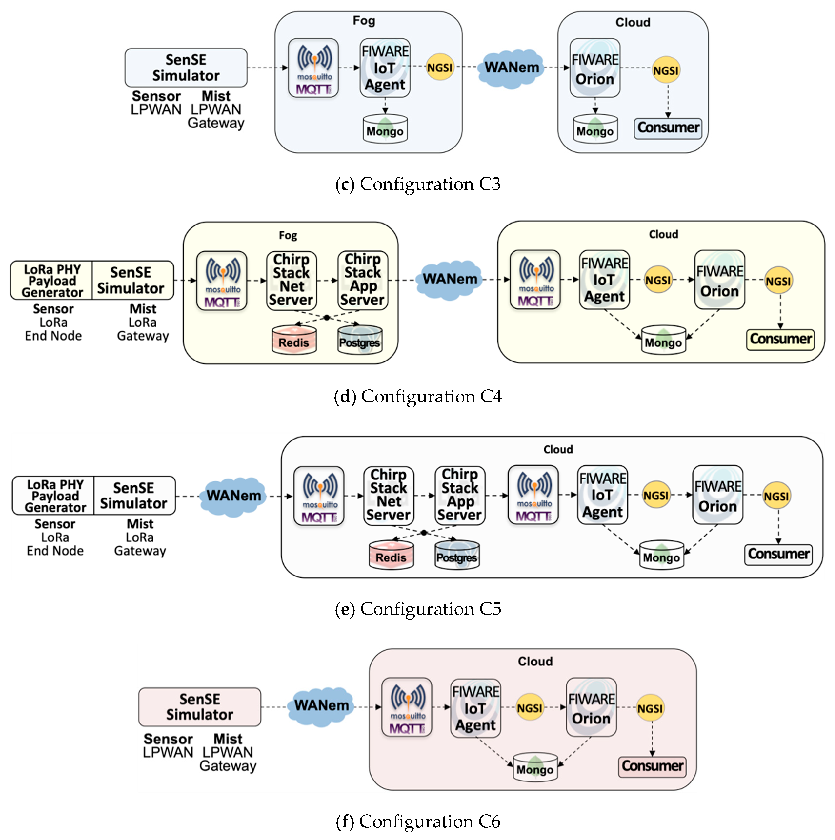
- Scenario simplicity: to clearly understand the effect of different deployment configurations-i.e., the mapping of IoTecture components into IoTinuum stages-a minimum set of components was used to guarantee a data flow that starts at sensors-actually, at SenSE-and ends at the consumer. The set of software components included in the evaluated IoT platform is composed of (Table 2): SenSE sensor simulator, ChirpStack, FIWARE IoT Agent, FIWARE Orion, and consumer. They include other auxiliary components as MQTT broker and databases (MongoDB, Redis), represented in Figure 6.
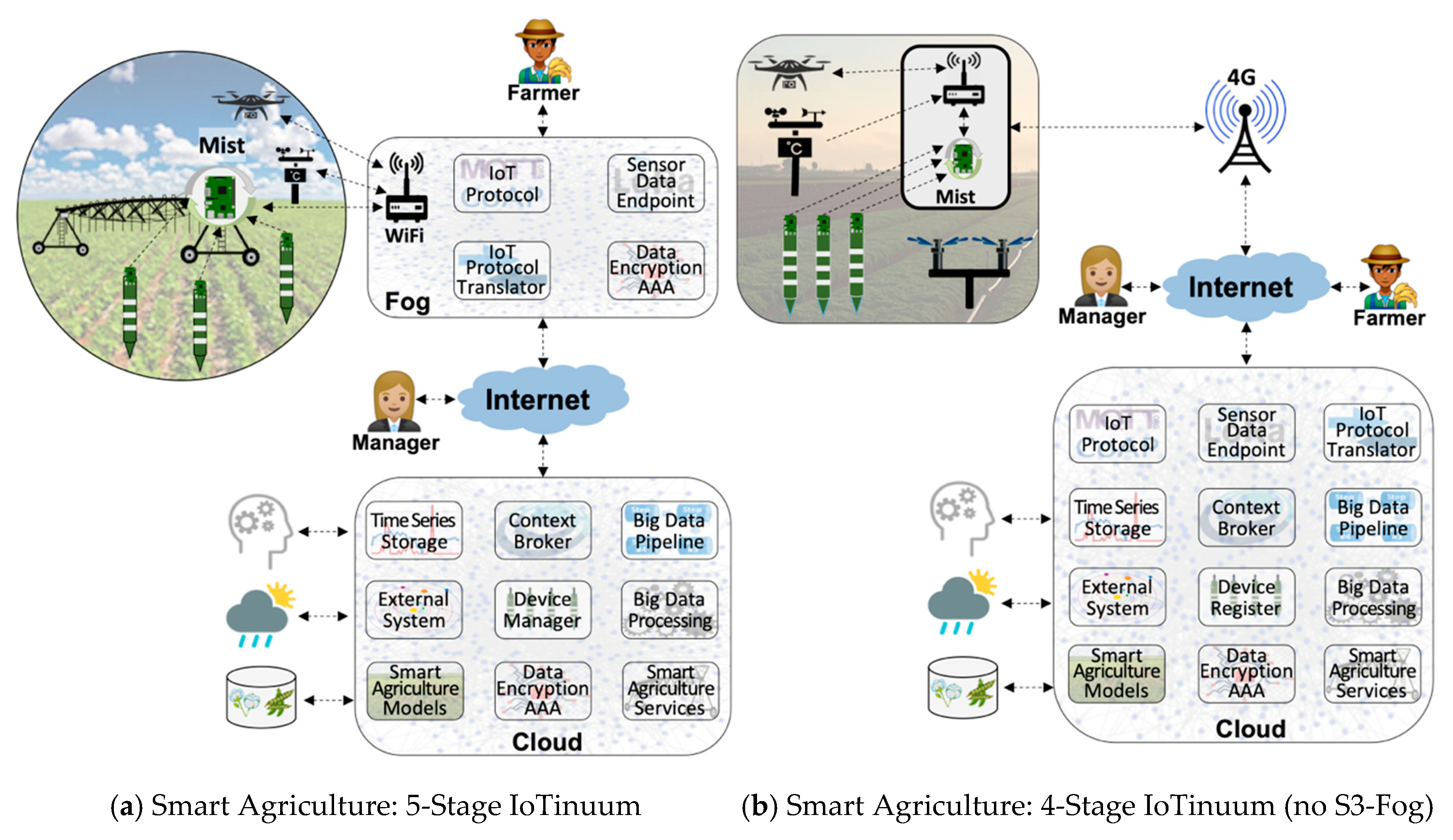
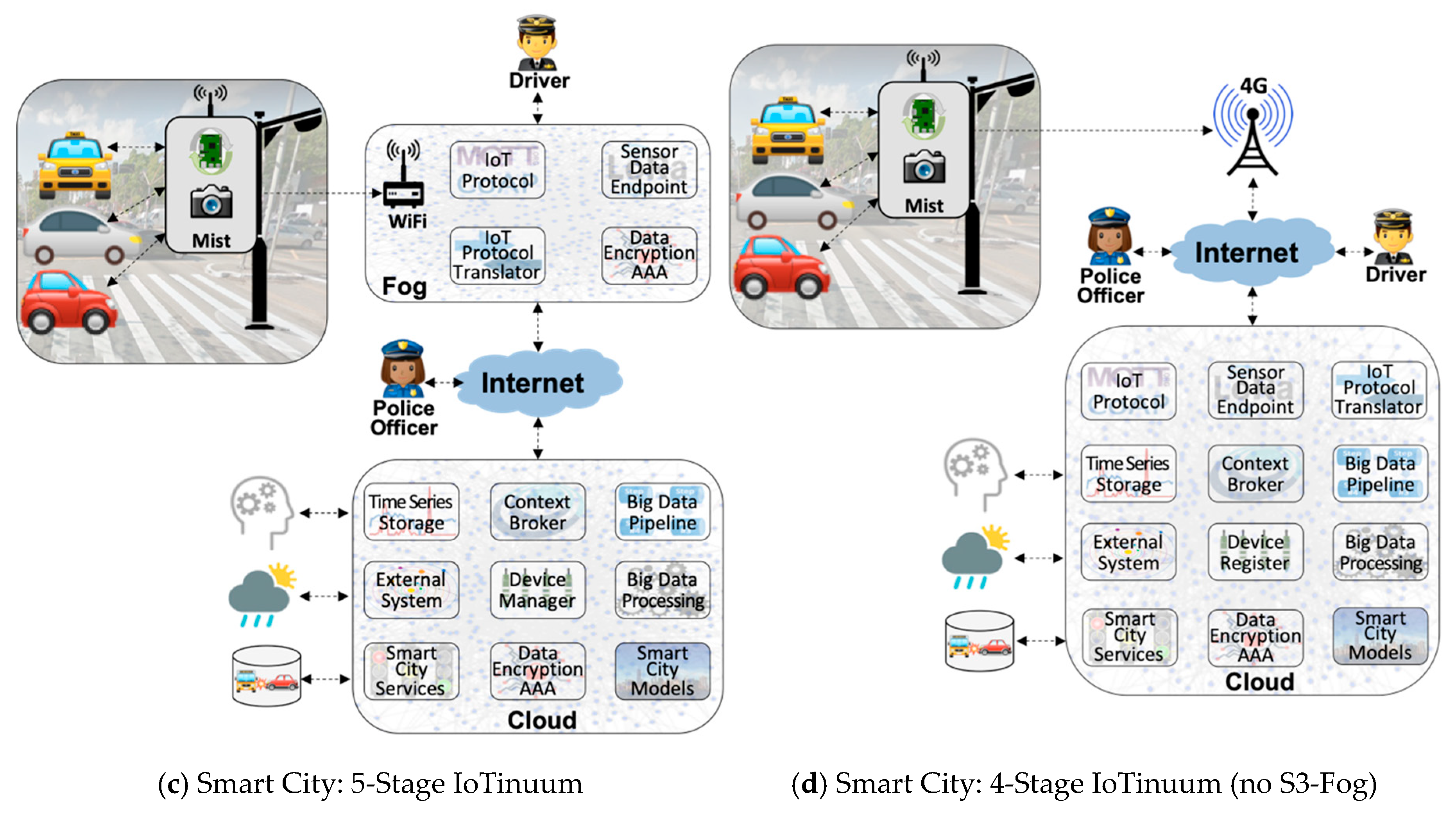
- Fog Dilemma: S3-Fog may frequently leave behind in specific configurations for different reasons, such as the choice of the farmer in not hosting IoT infrastructure within the farm in locations with stable and high-speed 4G connections. S2-Mist is required in most cases, especially for LoRaWAN. Also, we assume that S4-Cloud is always present. Therefore, we tested different configurations, with and without S3-Fog, and with heavyweight fog-local processing components-and lightweight fog-only communication components.
- Configurations C1, C2, C3, and C4 contain S3-Fog, whereas configurations C5 and C6 preclude it. It also implies that the former configurations assume Wi-Fi WLAN connectivity between S2-Mist and S3-Fog, while the latter assumes a 4G connection. The difference between Wi-Fi and 4G here is related to the link characteristics emulated by the WANem WAN emulator [57].
- Configurations C1, C4, and C5 use LoRaWAN, while configurations C2, C3, and C6 assume a generic LPWAN technology–e.g., the physical LoRa modulation.
- Configurations C1 and C2 have a heavyweight fog, which means that data are processed and consumed there with low latency. It also means that since we are using FIWARE Orion as the primary data distributor, one Orion in S3-Fog must connect to another Orion in S4-Cloud. Since Orion is a publish/subscribe context broker, the S4-Cloud Orion subscribes to the S3-Fog Orion, and whenever a message is published, the latter notifies the former. On the other hand, configurations C3 and C4 are based lightweight S3-Fog versions running only L2-Transport components, where C3 only has ChirpStack, and C4 only has the IoT Agent.
4.2. Experimental Design
- Smart applications: two scenarios of smart agriculture and smart city are considered in our experiments. The critical difference between them is the approach for sensor data generation. In the smart agriculture scenario, we consider many soil moisture sensor probes, continually generating and transmitting one data packet every 10 min. In the smart city scenario, we consider vehicles playing the role of sensors that communicate with a traffic light according to a Poisson arrival rate. In both scenarios, the SenSE sensor simulator synthetically generates sensor data.
- LPWAN Technology: data is generated by SenSE using the Ultralight 2.0 protocol format in both scenarios. Also, for LoRaWAN, sensor data packets are coded according to the LoRa PHY format and encrypted according to the AES algorithm determined by the LoRaWAN standard. For Generic LPWAN, plain sensor data is transmitted directly to the receiving end, which is always an MQTT broker. There is a sizeable difference in the payload generated by SenSE in the configurations with LoRaWAN and generic LPWAN. With LoRaWAN, SenSE sends ChirpStack a JSON over MQTT message with information about the emulated LoRa modulation in addition to the actual encrypted payload, composing a message of 314 bytes. In the configurations without LoRaWAN, SenSE sends an Ultralight 2.0-structured MQTT 65-byte message to the IoT Agent, significantly smaller than the LoRa message
- S1-Thing and S2-Mist: the SenSE simulator abstracts L1-Device in both S1-Thing and S2-Mist for all configurations. In other words, since our experiments are controlled and performed in a testbed, L1-Device is not present, except for the LoRa PHY format that is generated by SenSE, in order to understand the real effect of ChirpStack.
- ChirpStack: an open source LoRa server composed of two main components, the ChirpStack Network Server and the ChirpStack application server. Both communicate via MQTT with each other and with sensors and actuators, as well as platform components, e.g., FIWARE IoT Agent. Also, they use Redis and PostgreSQL as databases.
- WAN Emulation: to emulate the network link between the fog and the cloud, we used a WAN emulator (WANem) with 45 ms of latency and 5 ms of jitter. We defined the parameters to input in the WANem through a simple experiment performed the ping command to a VM located in the Amazon cloud in São Paulo, sent through 4G.
- Infrastructure: experiments were performed in an OpenStack-powered private cloud. As experiments were in a testbed, they are not influenced by other virtual machines running in the same physical servers. VMs for cloud and fog are based on standard Amazon AWS configurations: cloud runs on a t2.medium instance (2vCPU-4GB of RAM) and fog on a t2.small instance (1vCPU–2 GB RAM). Our testbed was composed of two physical servers with the following configuration: Intel(R) Xeon(R) CPU E3-1240 V2 @ 3.40GHz-8 cores and 16 GB of RAM.
4.3. Metrics
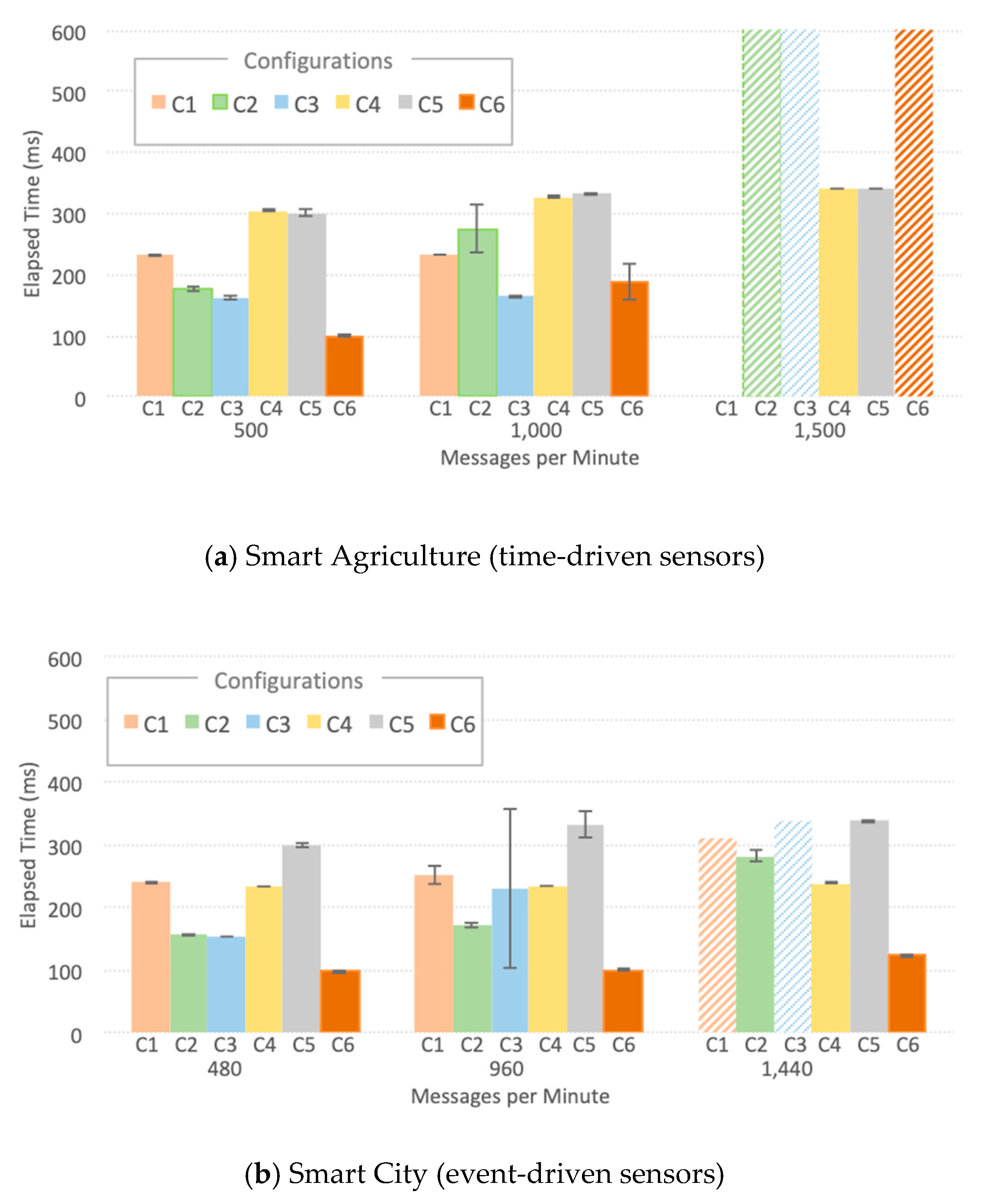
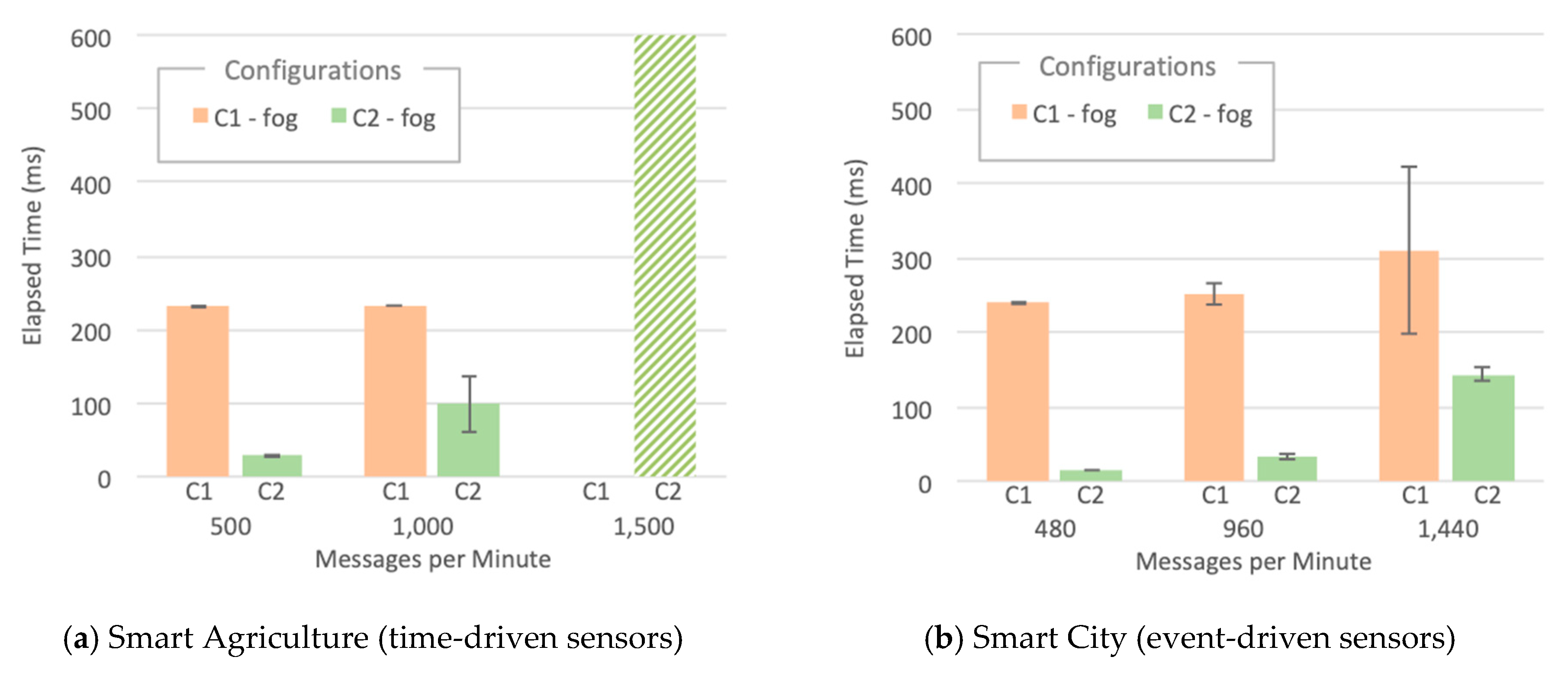
- Elapsed Time: The average time taken since a sensor data point is generated by SenSE until the consumer receives it. This metric represents how long it takes for sensor data to be available to any subscribed application. We present the Thing-to-Cloud Elapsed Time that encompasses the end-to-end path taken by data from its inception by SenSE in S1-Thing up to its consumption in S4-Cloud, and Thing-to-Fog Elapsed Time specifically for configurations C1 and C2 that contains an L4-Model Consumer application in S4-Cloud.
- System metrics: CPU and RAM usage per Docker container, which allows observing each component, located in S3-Fog or in S4-Cloud, collected every 5 s.
5. Performance Analysis: Results
- The LoRaWAN IoT Agent located at S3-Fog crashes in configuration C1 with the high workload for the smart city scenario due to spikes in CPU usage as depicted in Figure 9. A few seconds after a certain threshold of messages per second is reached, the CPU usage goes up to 100%, and this component presents a type of instability similar to a phase transition, leading it to crash soon after 341 s of the experiment.
- The Ultralight 2.0 IoT Agent located at both S3-Fog and S4-Cloud crashes in configurations C2, C3, and C5 with the high workload for the smart agriculture scenario due to a linear and constant increase in memory usage. Figure 10a shows it keeps allocation memory up to 239 s and crashes, which corresponds to the CPU usage of MongoDB, and also Orion, at S4-Cloud. Figure 10b shows that after the IoT Agent crashes, the CPU usage of MongoDB drops from more than 70% to almost zero after 40 s. In other words, the crash of the IoT Agent in S3-Fog is instead a consequence of another performance bottleneck located at S4-Cloud. The service time of the IoT Agent is shorter than the joint service time of Orion and MongoDB so that the former queues messages waiting for HTTP REST requests to be answered by the latter. In other words, the IoT Agent waits for a TCP ACK packet to free the memory allocated for the messages. As the message flow is constant in the smart agriculture scenario, the memory allocated by the IoT Agent increases boundlessly up to a point the operating system fails to provide more space, and it crashes. The high usage of CPU by MongoDB does not affect the performance of the platform since the IoT Agent crashes before the database starts to present significant problems.
- ChirpStack is a well-developed and stable software component that adequately uses system resources. The combined CPU Usage of all individual components that make up ChirpStack was around 40% for high workloads and 6% for low workloads, whereas the sum of memory usage was approximately 30 MB for high workloads and 22 MB for low workloads. Except for C1, all the configurations that crashed during the experiments were not based on LoRaWAN and consequently did not use ChirpStack. We conclude that, in addition to performing his LoRaWAN functions, the ChirpStack also works as a cushion for sensor data that softens message spikes that prevent IoT Agent to queue too many messages.
- The smart agriculture and smart city scenarios presented a similar performance for low and medium workloads. In those cases, the difference in the probability distribution for message generation did not impact the system performance, unlike for high workloads, where all experiments with Generic LPWAN (no ChirpStack) crashed for smart agriculture. On the other hand, in the smart city scenario, configurations C2 and C5 ran to the end of the experiment, and C3 was the only one with LoRaWAN that faced problems. This behavior indicates that the system can better handle traffic in bursts than in a constant flow of messages, because the time between bursts is enough for Orion to dequeue some messages and send ACKs back to the IoT Agent, freeing some memory in the process.
6. Discussion
6.1. Performance and Scalability Concerns
6.2. IoT Architectural Layers vs. Deployment Stages
6.3. Limitations and Future Work
7. Conclusions
Author Contributions
Funding
Conflicts of Interest
References
- Ericsson. Cellular Networks for Massive IoT, White Paper, UEN 284 23-3278, January 2016. Available online: https://www.ericsson.com/res/docs/whitepapers/wp_iot.pdf (accessed on 20 December 2019).
- Sharma, N.; Shamkuwar, M.; Singh, I. The History, Present and Future with IoT. In Internet of Things and Big Data Analytics for Smart Generation; Springer: Basel, Switzerland, 2019; pp. 27–51. [Google Scholar]
- Ahmed, E.; Yaqoob, I.; Gani, A.; Imran, M.; Guizani, M. Internet-of-Things-based Smart Environments: State of the Art, Taxonomy, and Open Research Challenges. IEEE Wirel. Commun. 2016, 23, 10–16. [Google Scholar] [CrossRef]
- Kamienski, C.; Soininen, J.-P.; Taumberger, M.; Dantas, R.; Toscano, A.; Salmon Cinotti, T.; Filev Maia, R.; Torre Neto, A. Smart Water Management Platform: IoT-Based Precision Irrigation for Agriculture. Sensors 2019, 19, 276. [Google Scholar] [CrossRef] [PubMed]
- Tzounis, A.; Katsoulas, N.; Bartzanas, T.; Kittas, C. Internet of Things in Agriculture, Recent Advances and Future Challenges. Biosyst. Eng. 2017, 164, 31–48. [Google Scholar] [CrossRef]
- Del Esposte, A.; Kon, F.; Costa, F.; Lago, N. InterSCity: A Scalable Microservice-Based Open Source Platform for Smart Cities. In Proceedings of the 6th International Conference on Smart Cities and Green ICT Systems, Porto, Portugal, 22–24 April 2017. [Google Scholar]
- Zanella, A.; Bui, N.; Castellani, A.; Vangelista, L.; Zorzi, M. Internet of Things for Smart Cities. IEEE Internet Things J. 2014, 1, 22–32. [Google Scholar] [CrossRef]
- Islam, S.; Kwak, D.; Kabir, M.; Hossain, M.; Kwak, K. The Internet of Things for Health Care: A Comprehensive Survey. IEEE Access 2015, 3, 678–708. [Google Scholar] [CrossRef]
- Wollschlaeger, M.; Sauter, T.; Jasperneite, J. The Future of Industrial Communication: Automation Networks in the Era of the Internet of Things and Industry 4.0. IEEE Ind. Electron. Mag. 2017, 11, 17–27. [Google Scholar] [CrossRef]
- Yun, M.; Yuxin, B. Research on the Architecture and Key Technology of Internet of Things (IoT) Applied on Smart Grid. In Proceedings of the IEEE 2010 International Conference on Advances in Energy Engineering, Beijing, China, 19–20 June 2010. [Google Scholar]
- Guth, J.; Breitenbücher, U.; Falkenthal, M.; Leymann, F.; Reinfurt, L. Comparison of IoT Platform Architectures: A Field Study Based on a Reference Architecture. In Proceedings of the 2016 IEEE Cloudification of the Internet of Things (CIoT), Paris, France, 23–25 November 2016. [Google Scholar]
- Omoniwa, B.; Hussain, R.; Javed, M.A.; Bouk, S.H.; Malik, S.A. Fog/Edge Computing-based IoT (FECIoT): Architecture, Applications, and Research Issues. IEEE Internet Things J. 2019, 6, 4118–4149. [Google Scholar] [CrossRef]
- Khan, R.; Khan, S.U.; Zaheer, R.; Khan, S. Future Internet: The Internet of Things Architecture, Possible Applications and Key Challenges. In Proceedings of the IEEE 10th International Conference on Frontiers of Information Technology, Islamabad, Pakistan, 17–19 December 2012. [Google Scholar]
- Mashal, I.; Alsaryrah, O.; Chung, T.Y.; Yang, C.Z.; Kuo, W.H.; Agrawal, D.P. Choices for interaction with things on Internet and underlying issues. Ad Hoc Netw. 2015, 28, 68–90. [Google Scholar] [CrossRef]
- Bellavista, P.; Corradi, A.; Foschini, L.; Scotece, D. Differentiated Service/Data Migration for Edge Services Leveraging Container Characteristics. IEEE Access 2019, 7, 139746–139758. [Google Scholar] [CrossRef]
- Mekki, K.; Bajic, E.; Chaxel, F.; Meyer, F. A comparative study of LPWAN technologies for large-scale IoT deployment. ICT Express 2019, 5, 1–7. [Google Scholar] [CrossRef]
- LoRa Alliance Technical Committee, 2017, LoRaWAN 1.1 Specification, October 2017. Available online: https://lora-alliance.org/resource-hub/lorawantm-specification-v11 (accessed on 13 September 2019).
- Clements, P. Documenting Software Architectures: Views and Beyond, 2nd ed.; Addison-Wesley: Boston, MA, USA, 2010. [Google Scholar]
- da Cruz, M.A.; Rodrigues, J.J.; Sangaiah, A.K.; Al-Muhtadi, J.; Korotaev, V. Performance Evaluation of IoT Middleware. J. Netw. Comput. Appl. 2018, 109, 53–65. [Google Scholar] [CrossRef]
- Yaqoob, I.; Ahmed, E.; Hashem, I.; Ahmed, A.; Gani, A.; Imran, M.; Guizani, M. Internet of Things Architecture: Recent Advances, Taxonomy, Requirements, and Open Challenges. IEEE Wirel. Commun. 2017, 24, 10–16. [Google Scholar] [CrossRef]
- Asif-Ur-Rahman, M.; Afsana, F.; Mahmud, M.; Kaiser, M.S.; Ahmed, M.R.; Kaiwartya, O.; James-Taylor, A. Toward a Heterogeneous Mist, Fog, and Cloud based Framework for the Internet of Healthcare Things. IEEE Internet Things J. 2019, 6, 4049–4062. [Google Scholar] [CrossRef]
- Singh, K.; Kapoor, D. Create Your Own Internet of Things: A Survey of IoT Platforms. IEEE Consum. Electron. Mag. 2017, 6, 57–68. [Google Scholar] [CrossRef]
- Razzaque, M.; Milojevic-Jevric, M.; Palade, A.; Clarke, S. Middleware for Internet of Things: A Survey. IEEE Internet Things J. 2016, 3, 70–95. [Google Scholar] [CrossRef]
- Hejazi, H.; Rajab, H.; Cinkler, T.; Lengyel, L. Survey of Platforms for Massive IoT. In Proceedings of the 2018 IEEE International Conference on Future IoT Technologies (Future IoT), Eger, Hungary, 18–19 January 2018. [Google Scholar]
- Broring, A.; Schmid, S.; Schindhelm, C.-K.; Khelil, A.; Kabisch, S.; Kramer, D.; Le Phuoc, D.; Mitic, J.; Anicic, D.; Teniente, E. Enabling IoT Ecosystems through Platform Interoperability. IEEE Softw. 2017, 34, 54–61. [Google Scholar] [CrossRef]
- Frustaci, M.; Pace, P.; Aloi, G.; Fortino, G. Evaluating Critical Security Issues of the IoT World: Present and Future Challenges. IEEE Internet Things J. 2018, 5, 2483–2495. [Google Scholar] [CrossRef]
- Kouicem, D.E.; Bouabdallah, A.; Lakhlef, H. Internet of things security: A top-down survey. Comput. Netw. 2018, 141, 199–221. [Google Scholar] [CrossRef]
- FIWARE. FIWARE Open Source Platform. Available online: www.fiware.org (accessed on 5 December 2019).
- Open Mobile Alliance. NGSI Requirements, OMA-RD-NGSI-V1_0. Available online: http://www.openmobilealliance.org (accessed on 20 December 2019).
- FIWARE Ultralight 2.0 Protocol. Available online: http://fiware-iotagent-ul.rtfd.io (accessed on 20 December 2019).
- Gozalvez, J. New 3GPP standard for IoT. IEEE Veh. Technol. Mag. 2016, 11, 14–20. [Google Scholar] [CrossRef]
- Sigfox. Available online: http://sigfox.com (accessed on 20 December 2019).
- LoRa Alliance. Available online: http://lora-alliance.org, (accessed on 20 December 2019).
- ChirpStack. Available online: https://www.chirpstack.io (accessed on 16 December 2019).
- The Things Network. Available online: http://thethingsnetwork.org (accessed on 20 December 2019).
- Loriot. Available online: http://loriot.io (accessed on 20 December 2019).
- Bonomi, F.; Milito, R.; Natarajan, P.; Zhu, J. Fog computing: A platform for Internet of Things and analytics. In Big Data and Internet of Things: A Roadmap for Smart Environments; Springer: Cham, Switzerland, 2014. [Google Scholar]
- Mukherjee, M.; Shu, L.; Wang, D. Survey of Fog Computing: Fundamental, Network Applications, and Research Challenges. IEEE Commun. Surv. Tutor. 2018, 20, 1826–1857. [Google Scholar] [CrossRef]
- Aazam, M.; Huh, E.-N. Fog Computing: The Cloud-IoT/IoE Middleware Paradigm. IEEE Potentials 2016, 35, 40–44. [Google Scholar] [CrossRef]
- Shi, W.; Cao, J.; Zhang, Q.; Li, Y.; Xu, L. Edge computing: Vision and challenges. IEEE Internet Things J. 2016, 3, 637–646. [Google Scholar] [CrossRef]
- Yogi, M.K.; Chandrasekhar, K.; Kumar, G.V. Mist computing: Principles, trends and future direction. SSRG Int. J. Comput. Sci. Eng. 2017, 4. [Google Scholar] [CrossRef]
- Bormann, C.; Ersue, M.; Keranen, A.; Gomez, C. Terminology for Constrained-Node Networks. In Internet-Draft, Draft-Bormann-Lwig-7228bis-05; IETF: Fremont, CA, USA, 2019. [Google Scholar]
- Kleinschmidt, J.H.; Kamienski, C.; Prati, R.C.; Kolehmainen, K.; Aguzzi, C. End-to-End Security in the IoT Computing Continuum: Perspectives in the SWAMP Project. In Proceedings of the 1st Workshop on Validation and Verification in Future Cyber-Physical Systems (WAFERS), Natal, Brazil, 19 November 2019. [Google Scholar]
- Babovic, Z.; Protic, J.; Milutinovic, V. Web Performance Evaluation for Internet of Things Applications. IEEE Access 2016, 4, 6974–6992. [Google Scholar] [CrossRef]
- Miao, Y.; Li, W.; Tian, D.; Hossain, M.; Alhamid, M. Narrowband Internet of Things: Simulation and Modeling. IEEE Internet Things J. 2018, 5, 2304–2314. [Google Scholar] [CrossRef]
- Martínez, R.; Pastor, J.Á.; Álvarez, B.; Iborra, A. A Testbed to Evaluate the FIWARE-based IoT Platform in the Domain of Precision Agriculture. Sensors 2016, 16, 1979. [Google Scholar] [CrossRef] [PubMed]
- Bittencourt, L.; Immich, R.; Sakellariou, R.; Fonseca, N.; Madeira, E.; Curado, M.; Villas, L.; DaSilva, L.; Lee, C.; Rana, O. The Internet of Things, Fog and Cloud continuum: Integration and challenges. Internet Things 2018, 3–4, 134–155. [Google Scholar] [CrossRef]
- Zyrianoff, I.; Heideker, A.; Silva, D.; Kamienski, C. Scalability of an Internet of Things Platform for Smart Water Management for Agriculture. In Proceedings of the Workshop on Advances in IoT Based Methods for Smart Water Distribution and Management in Agriculture (IMSA 2018), Bologna, Italy, 13–16 November 2018. [Google Scholar]
- Kamienski, C.; Jentsch, M.; Eisenhauer, M.; Kiljander, J.; Ferrera, E.; Rosengren, P.; Thestrup, J.; Souto, E.; Andrade, W.; Sadok, D. Application Development for the Internet of Things: A Context-Aware Mixed Criticality Systems Development Platform. Comput. Commun. 2017, 104, 1–16. [Google Scholar] [CrossRef]
- OASIS. MQTT Version 5.0. OASIS Committee Specification 02. May 2018. Available online: http://docs.oasis-open.org/mqtt/mqtt/v5.0/cs02/mqtt-v5.0-cs02.pdf (accessed on 17 September 2019).
- FIWARE, Orion Context Broker. Available online: http://fiware-orion.rtfd.io (accessed on 20 December 2019).
- Apache Kafka. Available online: http://kafka.apache.org (accessed on 20 December 2019).
- Apache Spark. Available online: http://spark.apache.org (accessed on 20 December 2019).
- CrateDB. Available online: http://crate.io (accessed on 20 December 2019).
- Farrell, S. Low-Power Wide Area Network (LPWAN) Overview. In Internet RFC 8376; Internet Engineering Task Force: Fremont, CA, USA, 2018. [Google Scholar]
- Zyrianoff, I. SenSE—Sensor Simulation Environment. 2017, GitHub Repository. Available online: https://github.com/ivanzy/SenSE-Sensor-Simulation-Environment (accessed on 16 September 2019).
- Kalitay, H.K.; Nambiarz, M.K. Designing WANem: A Wide Area Network Emulator Tool. In Proceedings of the 3rd IEEE International Conference on Communication Systems and Networks (COMSNETS 2011), Honolulu, HI, USA, 18 January 2011. [Google Scholar]
- Zyrianoff, I.; Borelli, F.; Biondi, G.; Heideker, A.; Kamienski, C. Scalability of Real-Time IoT-Based Applications for Smart Cities. In Proceedings of the IEEE Symposium on Computers and Communications (ISCC 2018), Natal, Brazil, 25–28 June 2018. [Google Scholar]
- Light, R.A. Mosquitto: Server and client implementation of the MQTT protocol. J. Open Source Softw. 2017, 2. [Google Scholar] [CrossRef]
- InterSCity. Available online: http://interscity.org (accessed on 20 December 2019).
- Konker. Available online: http://konkerlabs.com (accessed on 20 December 2019).
- ThingsBoard. Available online: http://thingsboard.io (accessed on 20 December 2019).


| Configuration | Fog Dilemma | Communication Technology | ||
|---|---|---|---|---|
| Heavy-Weight | Light-Weight | No fog | ||
| C1 | ✓ | LoRaWAN | ||
| C2 | ✓ | Generic LPWAN | ||
| C3 | ✓ | Generic LPWAN | ||
| C4 | ✓ | LoRaWAN | ||
| C5 | ✓ | LoRaWAN | ||
| C6 | ✓ | Generic LPWAN | ||
| Component | Layer | Implementation | Description |
|---|---|---|---|
| SenSE Sensor Simulator | L1-Device | SenSE Tool [56] | The Sensor Simulating Environment (SenSE) is an open-source large-scale IoT sensor data generator able to abstract real devices and to model different complex scenarios, such as smart cities [58] and smart agriculture [48]. SenSE is a traffic workload generator that emulates heterogeneous sensors representing tens of thousands of IoT devices, sending data simultaneously via MQTT. Although the sensors are synthetic, the traffic is real. |
| ChirpStack | L2-Transport | ChirpStack [34] | Implementation of LoRaWAN that can be installed in a private deployment. Composed by ChirpStack Network Server and ChirpStack Application Server, Redis and PostgreSQL databases, and Mosquitto MQTT Broker [59]. |
| IoT Agent | L2-Transport | FIWARE | Translates specific data formats carried by IoT Protocols (such as Ultralight 2.0 over MQTT in this case) into standard FIWARE JSON NGSI model. IoT Agent stores its data in MongoDB. We considered two implementations of the IoT Agent: the FIWARE Ultralight 2.0 IoT Agent and a custom-made LoRaWAN IoT Agent. We developed the latter one since the existing one in the FIWARE repository is still unstable. |
| Orion | L3-Data | FIWARE | Orion is a publish/subscribe context broker with a central role in data distribution for the FIWARE platform. Orion works with entities defined in JSON NGSI and stores them directly in MongoDB. |
| Consumer | L4-Model | Specific purpose | A simple consumer of IoT data playing the role of a generic smart application model. |
| Factor | Level |
|---|---|
| Scenario | Smart Agriculture–Smart City |
| Workload | |
| 5000–10,000–15,000 (500–1000–1500 messages per minute) |
| 8–16–24 (480–960–1440 messages per minute) |
| Deployment configurations | C1–C2–C3–C4-C5-C6 |
© 2019 by the authors. Licensee MDPI, Basel, Switzerland. This article is an open access article distributed under the terms and conditions of the Creative Commons Attribution (CC BY) license (http://creativecommons.org/licenses/by/4.0/).
Share and Cite
Zyrianoff, I.; Heideker, A.; Silva, D.; Kleinschmidt, J.; Soininen, J.-P.; Salmon Cinotti, T.; Kamienski, C. Architecting and Deploying IoT Smart Applications: A Performance–Oriented Approach. Sensors 2020, 20, 84. https://doi.org/10.3390/s20010084
Zyrianoff I, Heideker A, Silva D, Kleinschmidt J, Soininen J-P, Salmon Cinotti T, Kamienski C. Architecting and Deploying IoT Smart Applications: A Performance–Oriented Approach. Sensors. 2020; 20(1):84. https://doi.org/10.3390/s20010084
Chicago/Turabian StyleZyrianoff, Ivan, Alexandre Heideker, Dener Silva, João Kleinschmidt, Juha-Pekka Soininen, Tullio Salmon Cinotti, and Carlos Kamienski. 2020. "Architecting and Deploying IoT Smart Applications: A Performance–Oriented Approach" Sensors 20, no. 1: 84. https://doi.org/10.3390/s20010084
APA StyleZyrianoff, I., Heideker, A., Silva, D., Kleinschmidt, J., Soininen, J.-P., Salmon Cinotti, T., & Kamienski, C. (2020). Architecting and Deploying IoT Smart Applications: A Performance–Oriented Approach. Sensors, 20(1), 84. https://doi.org/10.3390/s20010084