Refocusing Moving Ship Targets in SAR Images Based on Fast Minimum Entropy Phase Compensation


Abstract
:1. Introduction
2. Basic Procedures of Moving Ship Refocusing in SAR Images
- (a)
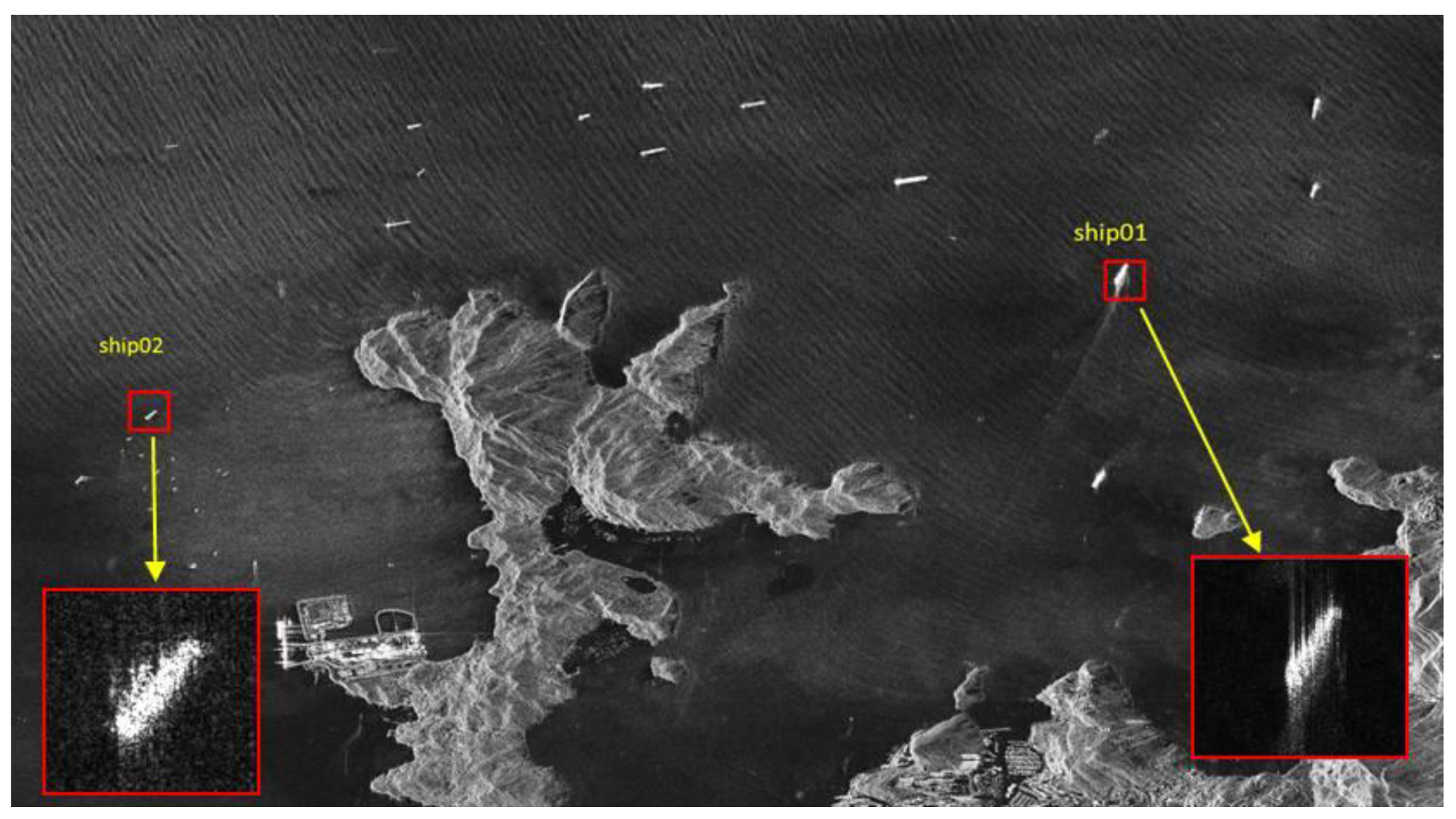
- Input a single look complex (SLC) image;
- (b)
- Implement ship detection with software;
- (c)
- Select sub-images, where each sub-image includes only a single defocused ship and has the same spatial resolution as the original image;
- (d)
- (e)
- Exploit ISAR processing to generate a focused image of the ship.
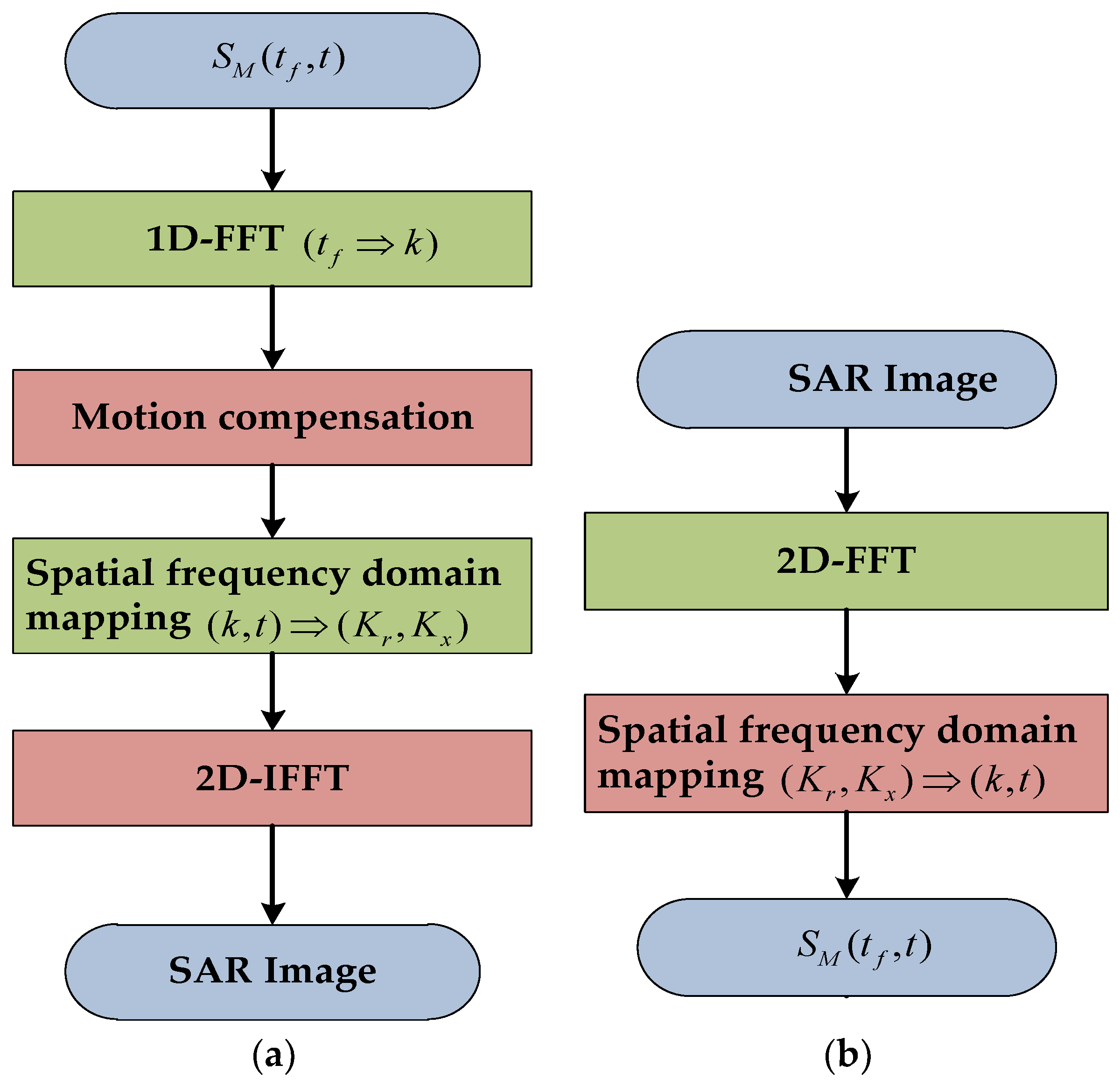
3. ISAR Processing Based on Fast Minimum Entropy Phase Compensation
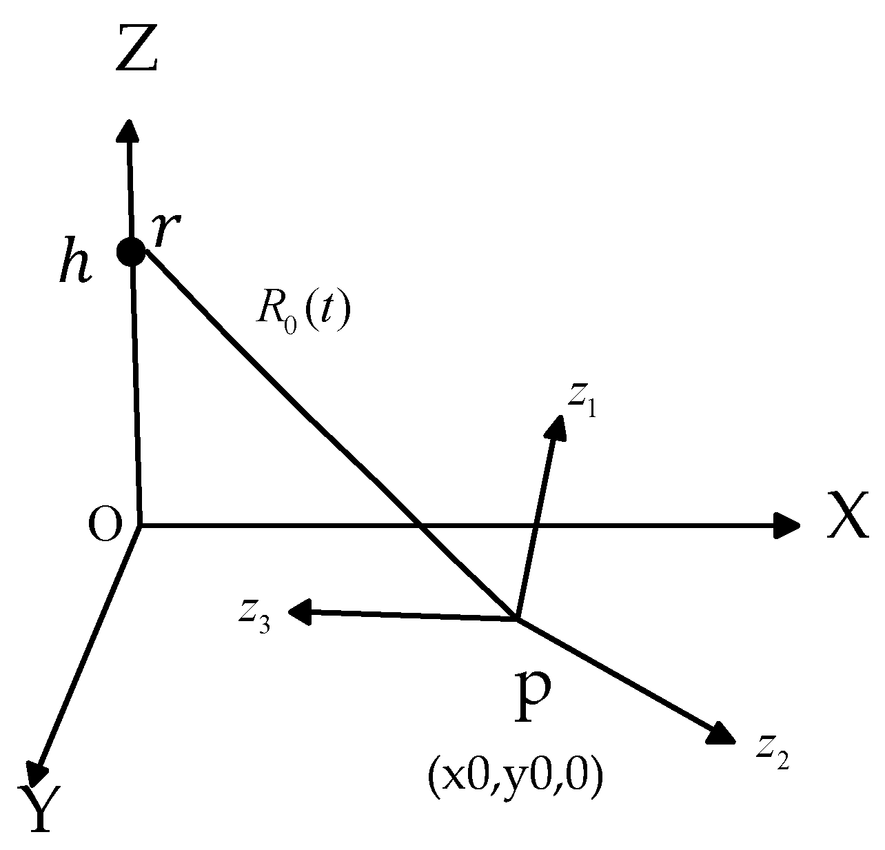
3.1. Signal Model
3.2. Phase Compensation Based on Fast Minimum Entropy Method
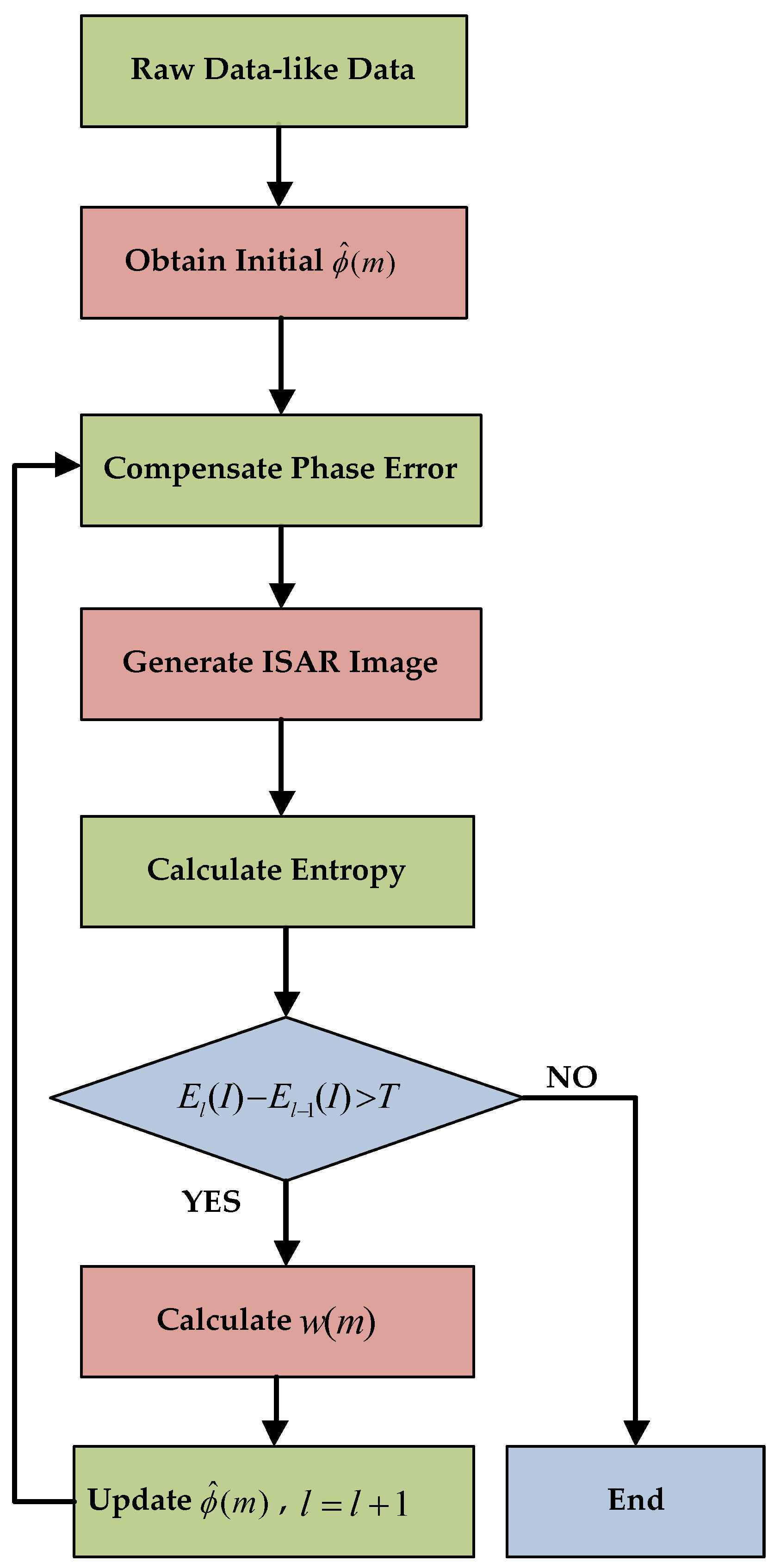
3.3. The Procedures of Phase Compensation Method
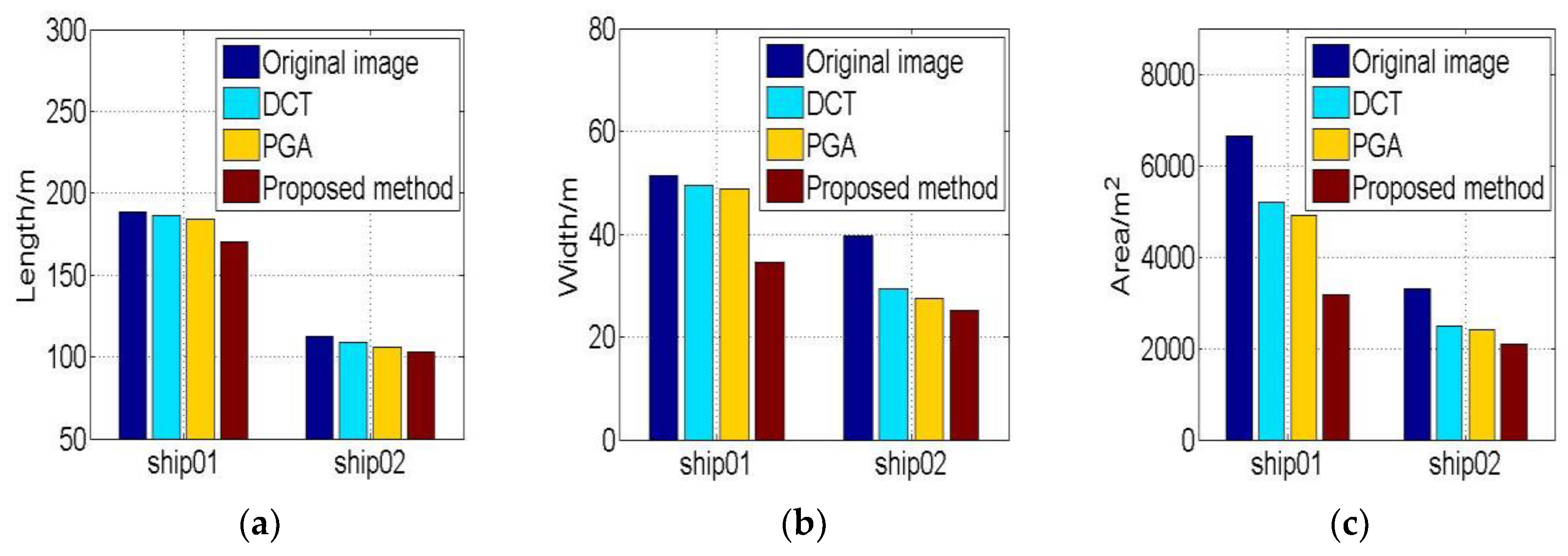
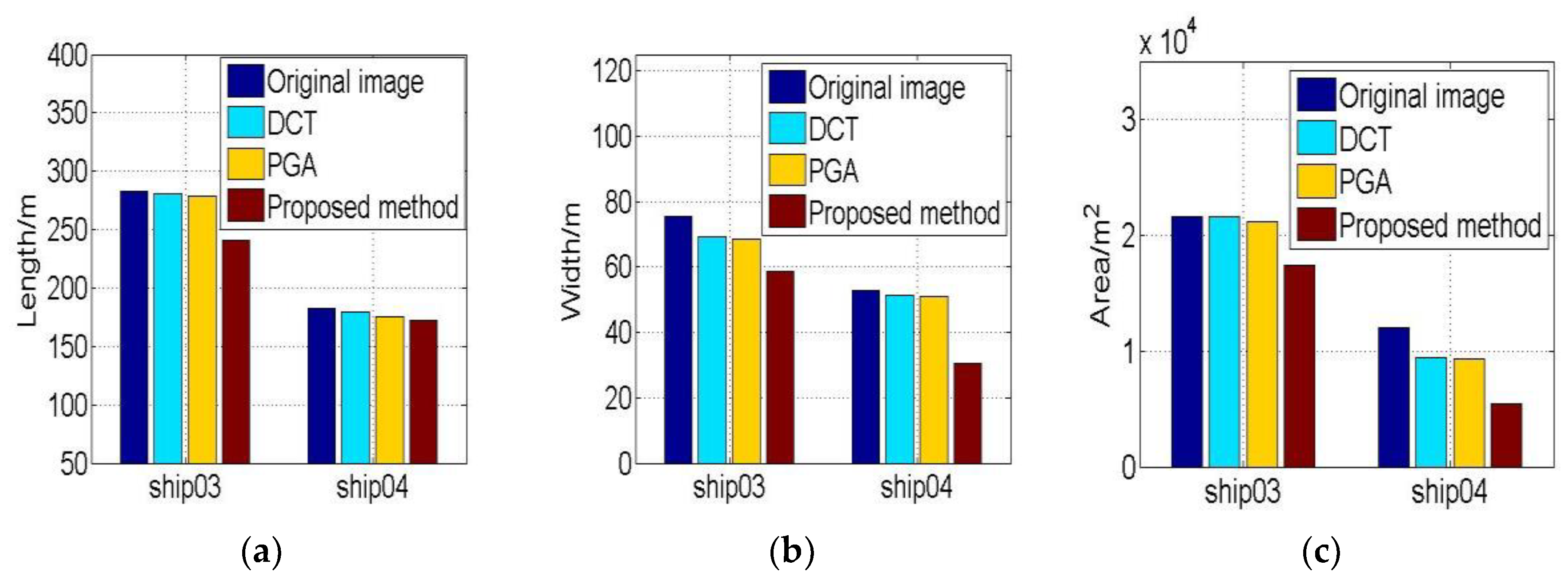
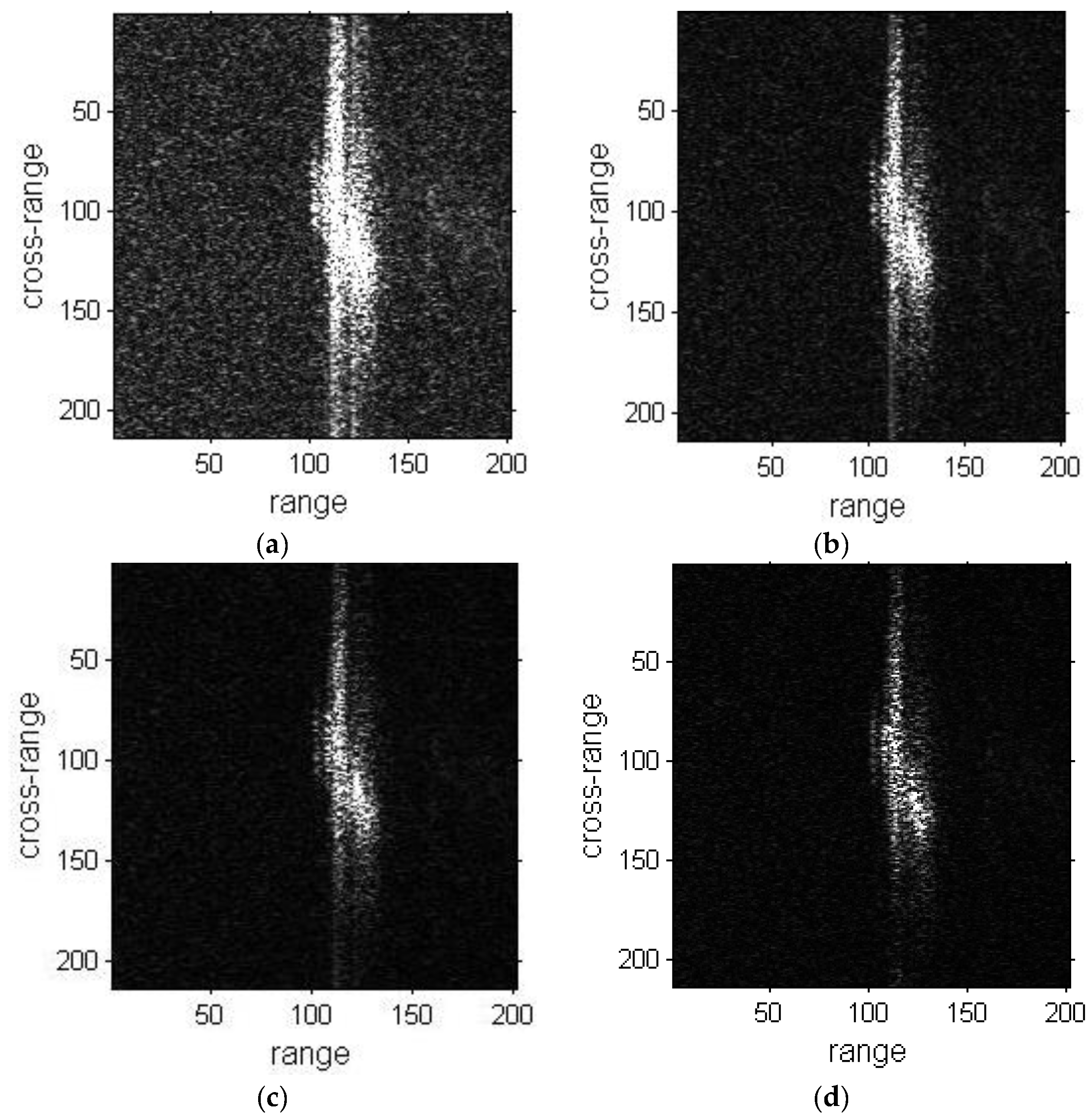
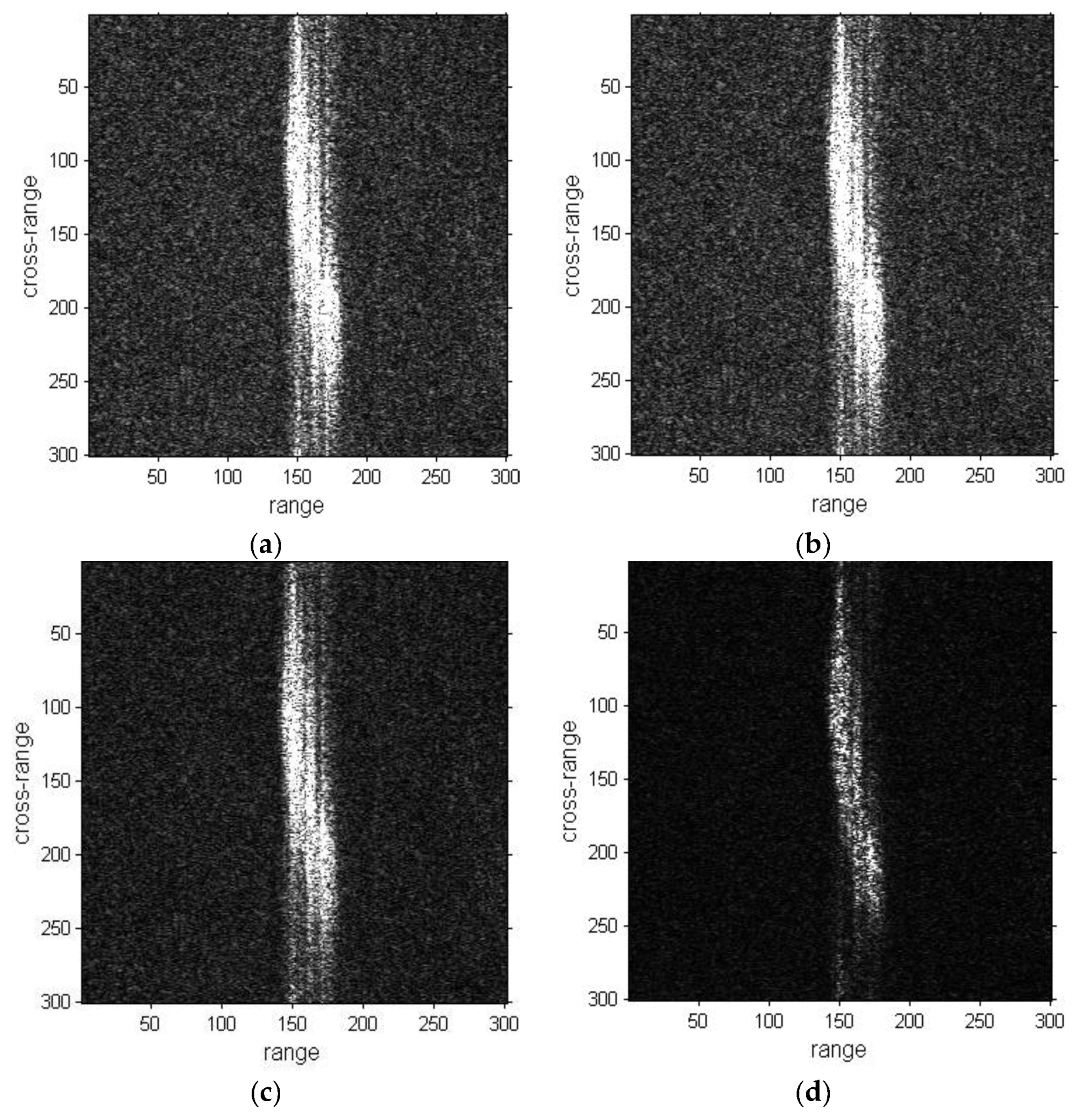
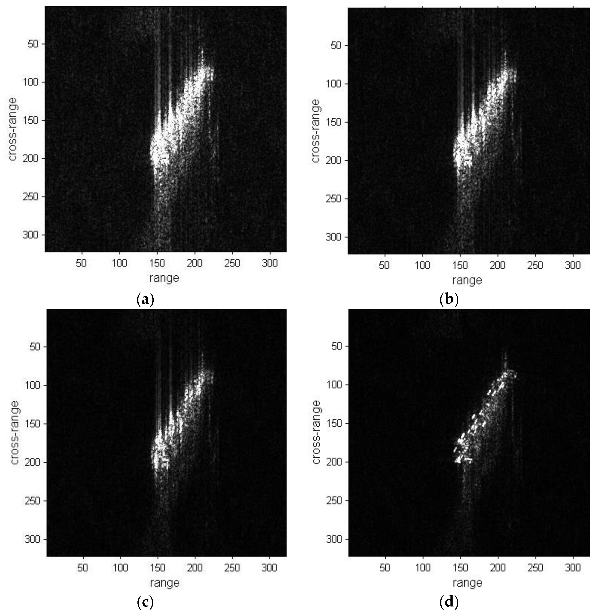
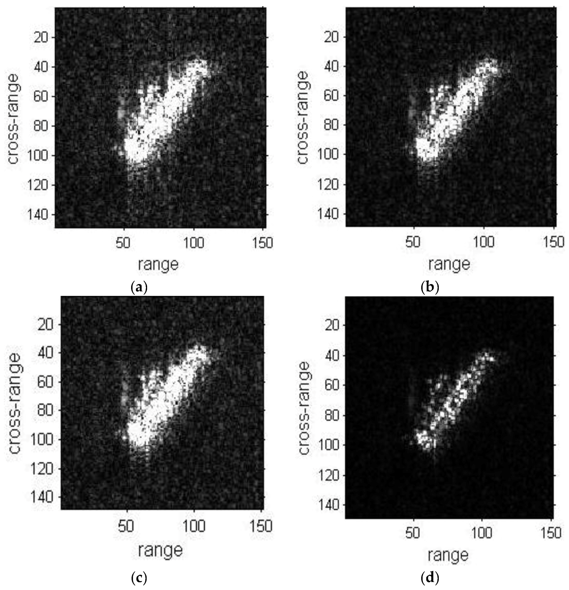
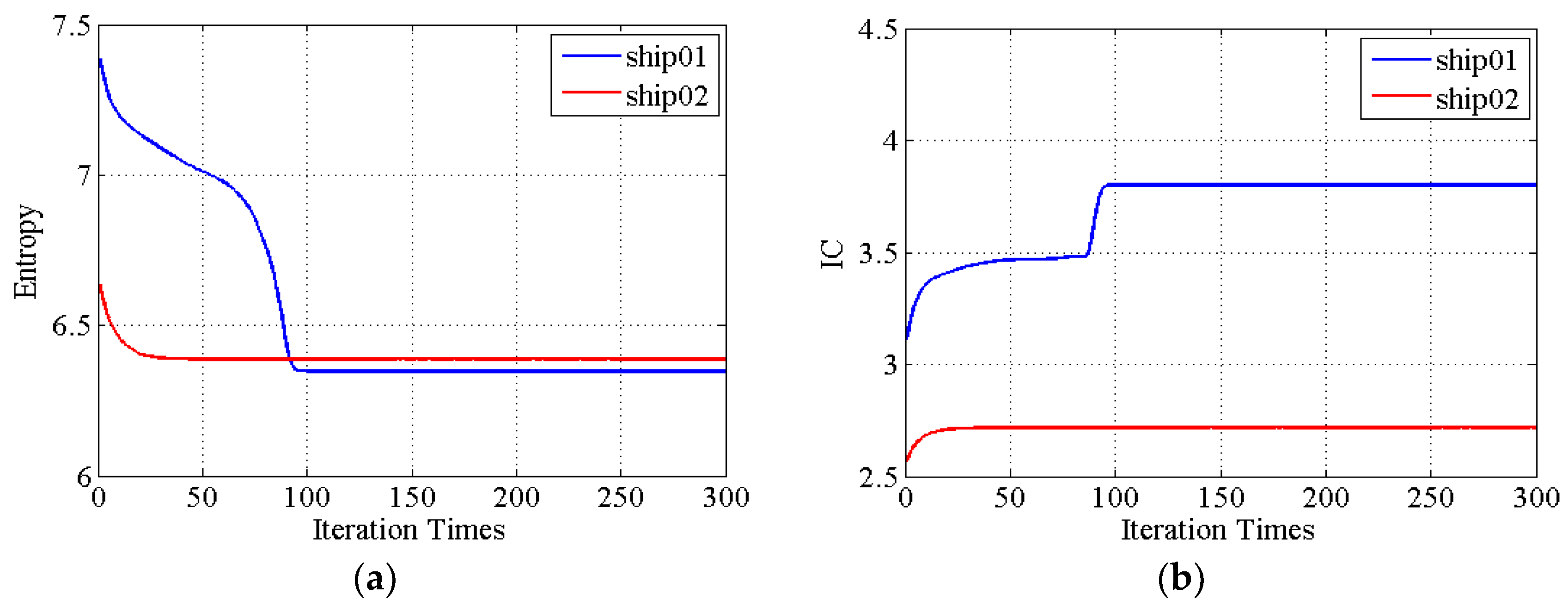
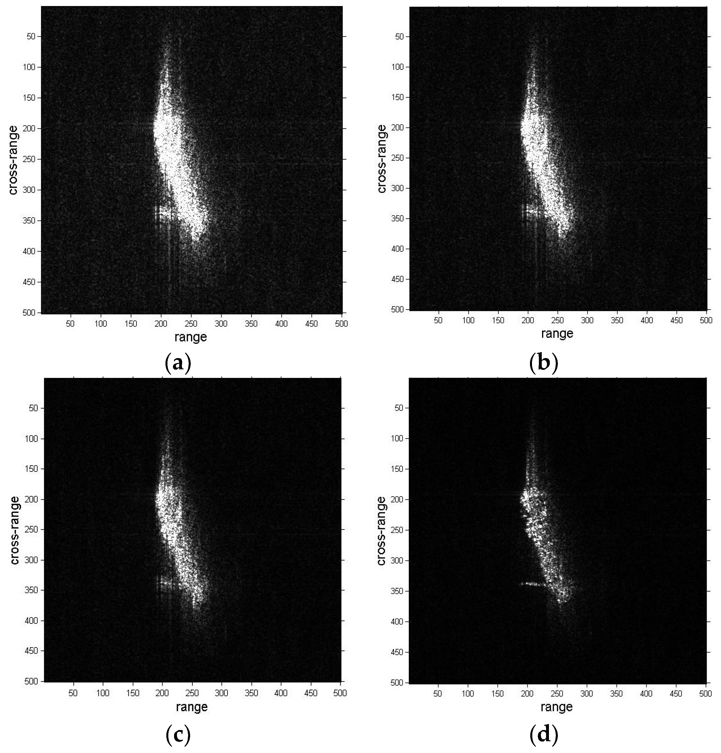
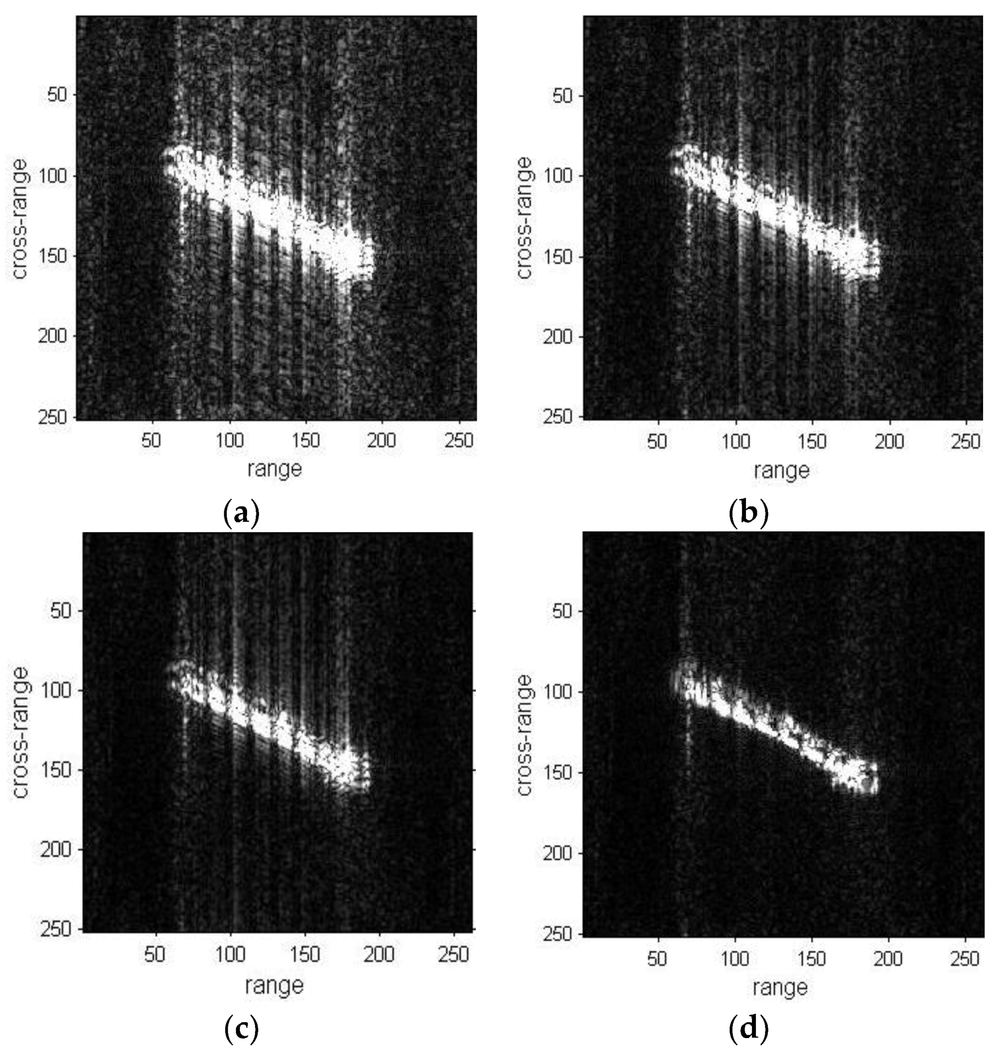
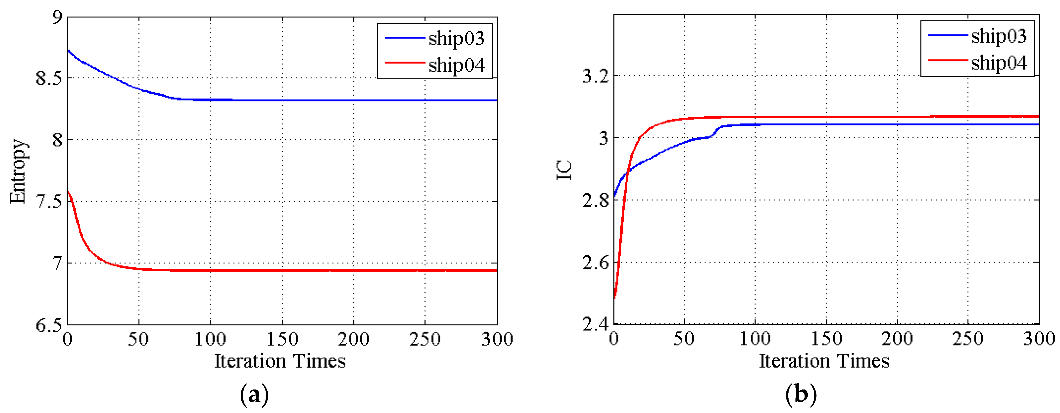
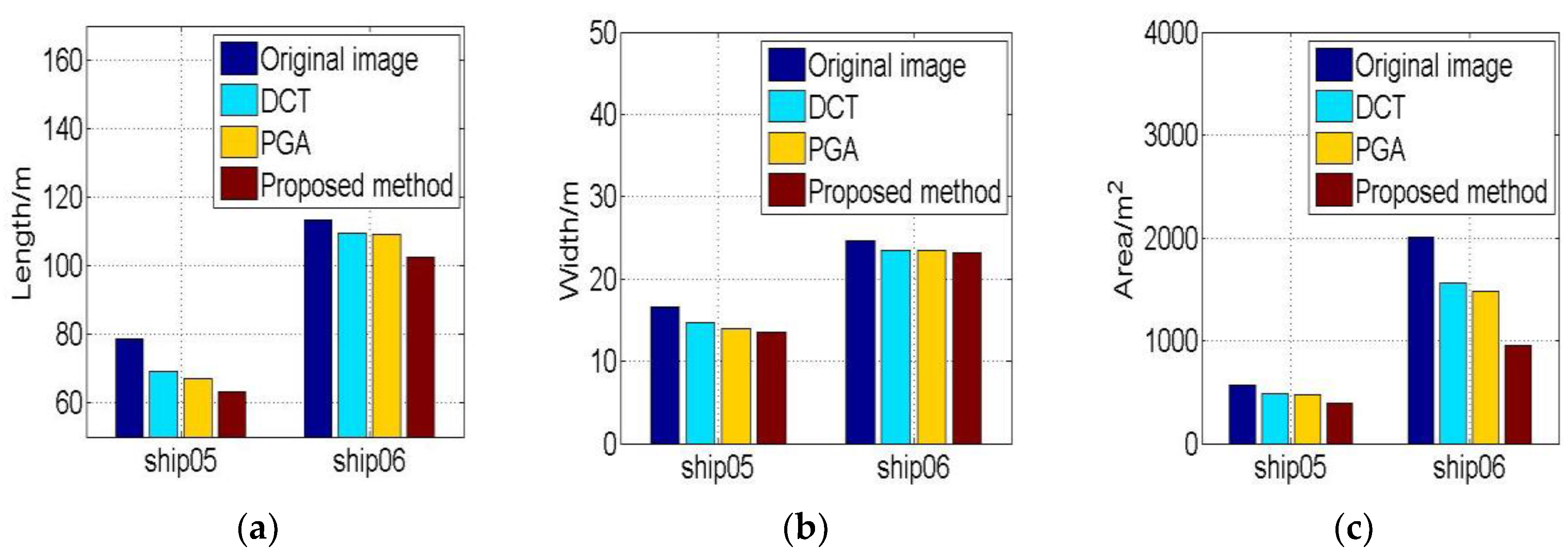
4. Experimental Results and Discussions
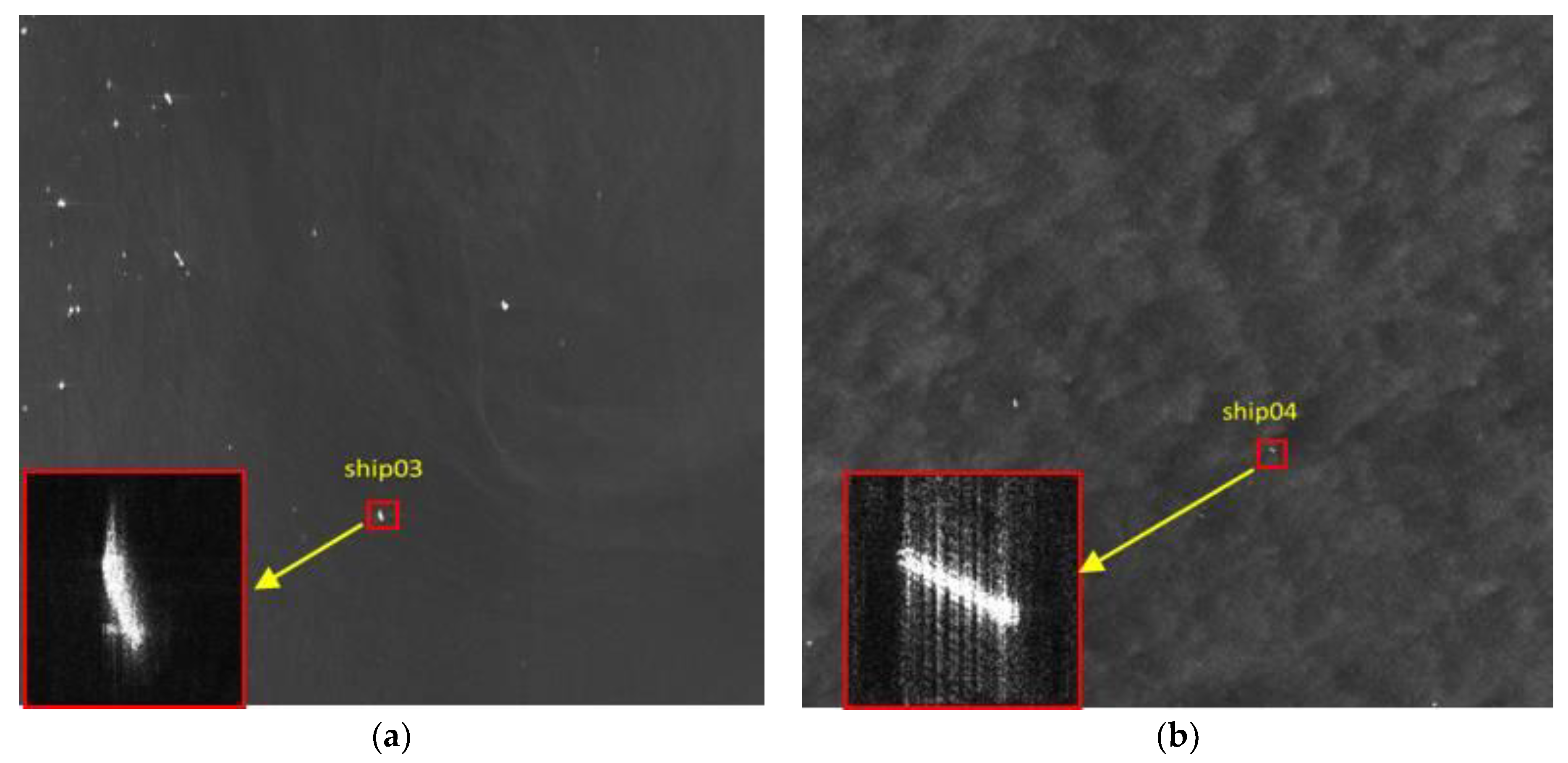
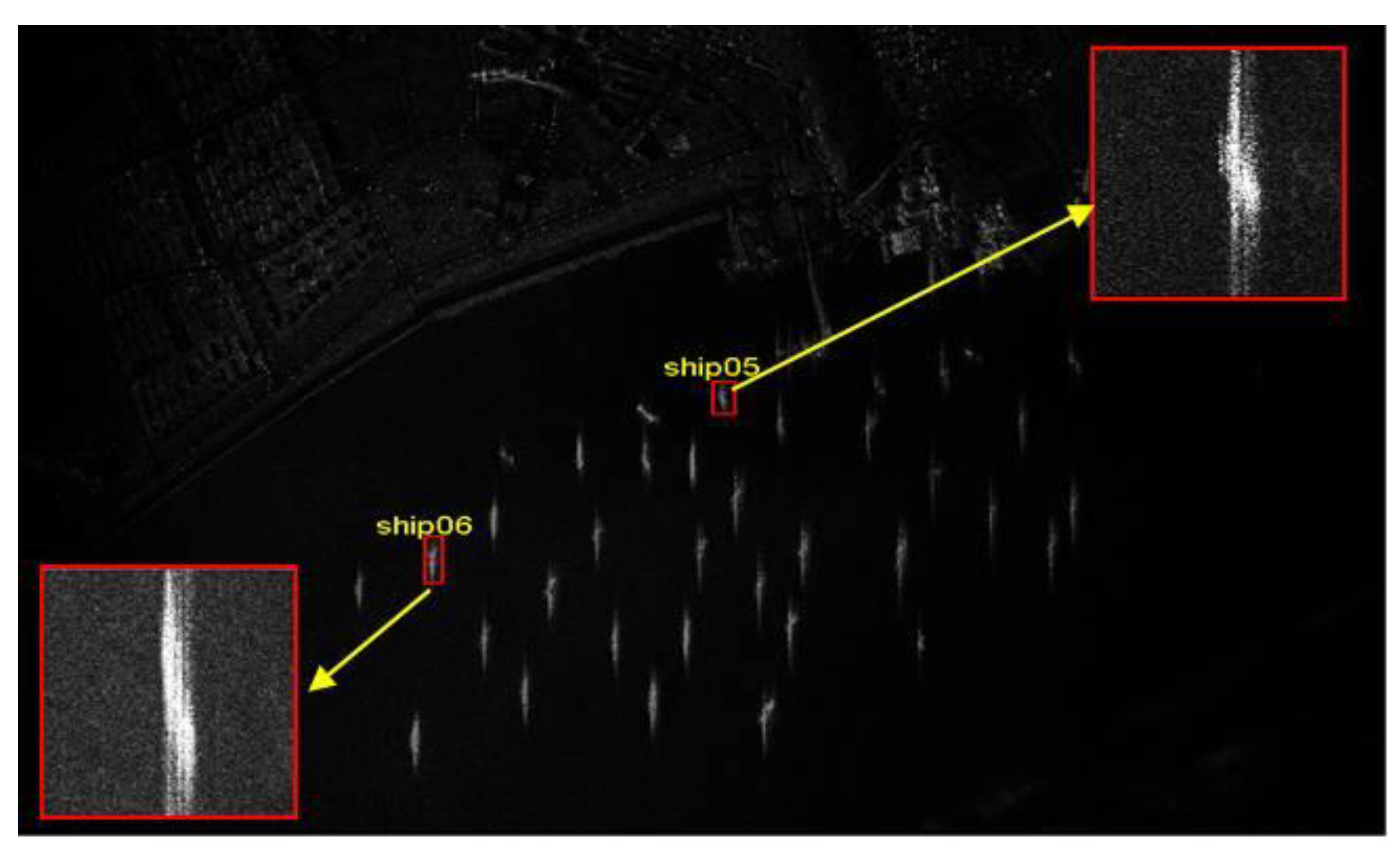
4.1. Spaceborne SAR Data
4.2. Airborne SAR Data
5. Conclusions
Author Contributions
Funding
Acknowledgments
Conflicts of Interest
References
- Martorella, M.; Pastina, D.; Berizzi, F.; Lombardo, P. Spaceborne radar imaging of maritime moving targets with the Cosmo-Skymed SAR system. IEEE J. Sel. Top. Appl. Earth Observ. Remote Sens. 2014, 7, 2797–2810. [Google Scholar] [CrossRef]
- Crisp, D.J. The State-of-the-Art in Ship Detection in Synthetic Aperture Radar Imagery; DSTO Information Sciences Laboratory: Edinburgh, Australia, 2004. [Google Scholar]
- Dong, G.; Kuang, G.; Wang, N.; Wang, W. Classification via sparse representation of steerable wavelet frames on Grossmann manifold: Application to target recognition in SAR image. IEEE Tran. Image Process. 2017, 26, 2892–2904. [Google Scholar] [CrossRef] [PubMed]
- Kang, M.; Ji, K.; Leng, X.; Xing, X.; Zou, H. Synthetic aperture radar target recognition with feature fusion based on a stacked autoencoder. Sensors 2017, 17, 192. [Google Scholar] [CrossRef] [PubMed]
- Noviello, C.; Fornaro, G.; Mertorella, M. Focused SAR image formation of moving targets based on Doppler parameter estimation. IEEE Trans. Geosci. Remote Sens. 2015, 53, 3460–3470. [Google Scholar] [CrossRef]
- Zhang, Y.; Sun, J.; Lei, P.; Li, G.; Hong, W. High-resolution SAR-based ground moving target imaging with defocused ROI data. IEEE Trans. Geosci. Remote Sens. 2016, 54, 1062–1073. [Google Scholar] [CrossRef]
- Wang, B.; Xu, S.; Wu, W.; Hu, P.; Chem, Z. Adaptive ISAR imaging of maneuvering targets based on a modified Fourier transform. Sensors 2018, 18, 1370. [Google Scholar] [CrossRef] [PubMed]
- Lv, X.; Xing, M.; Wang, C.; Zhang, S. ISAR imaging of maneuvering targets based on the range centroid Doppler technique. IEEE Tran. Image Process. 2010, 19, 141–153. [Google Scholar]
- Zheng, J.; Liu, H.; Liu, Z.; Liu, Q. ISAR imaging of ship targets based on an integrated cubic phase bilinear autocorrelation function. Sensors 2017, 17, 498. [Google Scholar] [CrossRef] [PubMed]
- Wang, J.; Liu, X. Improved global range alignment for ISAR. IEEE Trans. Aerosp. Electron. Syst. 2007, 43, 1070–1075. [Google Scholar] [CrossRef]
- Wang, J.; Kasilingam, D. Global range alignment for ISAR. IEEE Trans. Aerosp. Electron. Syst. 2003, 39, 351–357. [Google Scholar] [CrossRef]
- Steinberg, B. Radar imaging from a distorted array: The radio camera algorithm and experiment. IEEE Trans. Antennas Propag. 1981, 29, 740–748. [Google Scholar] [CrossRef]
- Zheng, B.; Wei, Y. Improvements of autofocusing techniques for ISAR motion compensation. Acta Electron. Sin. 1996, 24, 74–79. [Google Scholar]
- Wahl, D.E. Phase gradient autofocus—A robust tool for high resolution SAR phase correction. IEEE Trans. Aerosp. Electron. Syst. 1994, 30, 827–835. [Google Scholar] [CrossRef]
- Qing, J.; Xu, H.; Liang, X.; Li, Y. An improved phase gradient autofocus algorithm used in real-time processing. J. Radars 2015, 4, 600–607. [Google Scholar]
- Zhu, D.; Jiang, R.; Mao, X.; Zhu, Z. Multi-Subaperture PGA for SAR autofocusing. IEEE Trans. Aerosp. Electron. Syst. 2013, 49, 468–488. [Google Scholar] [CrossRef]
- Itoh, T.; Sueda, H.; Watanabe, Y. Motion compensation for ISAR via centroid tracking. IEEE Trans. Aerosp. Electron. Syst. 1996, 32, 1191–1197. [Google Scholar] [CrossRef]
- Zhu, Z.; Qiu, X.; She, Z. ISAR motion compensation using modified Doppler centroid tracking method. Trans. Nanjing Univ. Aeronaut. Astronaut. 1995, 12, 195–201. [Google Scholar]
- Martorella, M.; Berizzi, F.; Haywood, B. Contrast maximization based technique for 2-D ISAR autofocusing. IEE Proc. Radar Sonar Navig. 2005, 152, 253–262. [Google Scholar] [CrossRef]
- Berizzi, F.; Corsini, G. Autofocusing of inverse synthetic radar images using contrast optimization. IEEE Trans. Aerosp. Electron. Syst. 1996, 32, 1185–1191. [Google Scholar] [CrossRef]
- Simmons, S.; Evans, R. Maximum likelihood autofocusing of radar images. In Proceedings of the IEEE 1995 International Radar Conference, Alexandria, VA, USA, 8–11 May 1995; pp. 410–415. [Google Scholar]
- Berizzi, F.; Pinelli, G. Maximum-likelihood ISAR image autofocusing technique based on instantaneous frequency estimation. IEE Proc. Radar Sonar Navig. 1997, 144, 284–292. [Google Scholar] [CrossRef]
- Li, X.; Liu, G.; Ni, J. Autofocusing of ISAR images based on entropy minimization. IEEE Trans. Aerosp. Electron. Syst. 1999, 35, 1240–1251. [Google Scholar] [CrossRef]
- Yang, L.; Xing, M.; Zhang, L.; Sheng, J.; Bao, Z. Entropy-based motion error correction for high-resolution spotlight SAR imagery. IET Radar Sonar Navig. 2012, 6, 627–637. [Google Scholar] [CrossRef]
- Du, X.; Duan, C.; Hu, W. Sparse representation based autofocusing technique for ISAR images. IEEE Geosci. Remote Sens. Lett. 2013, 51, 1826–1835. [Google Scholar] [CrossRef]
- Martorella, M.; Giusti, E.; Berizzi, F.; Bacci, A.; Mese, E.D. ISAR based technique for refocusing non-cooperative targets in SAR images. IET Radar Sonar Navig. 2012, 6, 332–340. [Google Scholar] [CrossRef]
- Khwaja, A.; Ferro-Famil, L.; Pottier, E. Efficient SAR raw data generation for anisotropic urban scenes based on inverse processing. IEEE Geosci. Remote Sens. Lett. 2009, 6, 757–761. [Google Scholar] [CrossRef]
- Khwaja, A.; Ferro-Famil, L.; Pottier, E. SAR raw data generation using inverse SAR image formation algorithms. In Proceedings of the 2006 IEEE International Symposium on Geoscience and Remote Sensing (IGARSS), Denver, CO, USA, 31 July–4 August 2006. [Google Scholar] [CrossRef]
- Martorella, M.; Berizzi, F.; Giusti, E.; Bacci, A. Refocusing of moving targets in SAR images based on inversion mapping and ISAR processing. In Proceedings of the 2011 IEEE Radar Conference, Kansas, MO, USA, 23–27 May 2011; pp. 68–72. [Google Scholar]
- Martorella, M.; Acito, N.; Berizzi, F. Statistical CLEAN technique for ISAR imaging. IEEE Trans. Geosci. Remote. Sens. 2007, 45, 3552–3560. [Google Scholar] [CrossRef]
- Kang, M.; Bae, J.; Lee, S.; Kim, K. Efficient ISAR autofocus via minimization of Tsallis entropy. IEEE Trans. Aerosp. Electron. Syst. 2016, 52, 2952–2960. [Google Scholar] [CrossRef]
- Yang, J.; Zhang, Y. An airborne SAR moving target imaging and motion parameters estimation algorithm with azimuth-dechirping and the second-order keystone transform applied. IEEE J. Sel. Top. Appl. Earth Observ. Remote Sens. 2015, 8, 3967–3976. [Google Scholar] [CrossRef]
- Wang, J.; Liu, X. SAR minimum-entropy autofocus using an adaptive-order polynomial model. IEEE Geosci. Remote Sens. Lett. 2006, 3, 512–516. [Google Scholar] [CrossRef]
- Wu, W.; Hu, P.; Xu, S.; Chen, Z. Image registration for InSAR based on joint translational motion compensation. IET Radar Sonar Navig. 2017, 11, 1597–1603. [Google Scholar] [CrossRef]
- Zeng, T.; Wang, R.; Li, F. SAR image autofocus utilizing minimum-entropy criterion. IEEE Geosci. Remote Sens. Lett. 2013, 10, 1552–1556. [Google Scholar] [CrossRef]
- Leng, X.; Ji, K.; Zhou, S.; Xing, X.; Zou, H. An adaptive ship detection scheme for Spaceborne SAR imagery. Sensors 2016, 16, 1345. [Google Scholar] [CrossRef] [PubMed]


| Image | Image01 | Image02 | Image03 | Image04 |
|---|---|---|---|---|
| Product | TerraSAR-X | Gaofeng-3 | Gaofeng-3 | Airborne |
| Mode | Strip | UFS | UFS | Strip |
| Resolution (M) | 3 | 3 | 3 | 0.5 |
| PRF (Hz) | 3472.134984 | 2014.078491 | 1977.984863 | 500.0000 |
| Band (MHz) | 120.00 | 80.00 | 80.00 | 150.00 |
| Polarization | VV | HH | HH | HH |
| Wave Length (m) | 0.031040 | 0.055517 | 0.055517 | 0.056564 |
| Slant-Range (km) | 629.17 | 7127.22 | 7137.52 | 4.62 |
| Velocity (m/s) | 7088.636524 | 7563.162316 | 7568.372931 | 55.599743 |
| Sub-Image | ship01 | ship02 | ship03 | ship04 | ship05 | ship06 |
|---|---|---|---|---|---|---|
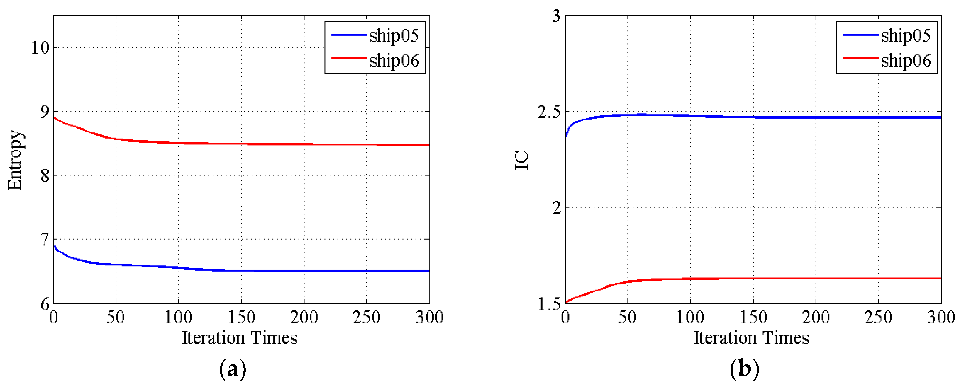
| Original Image | 7.39 | 6.59 | 8.72 | 7.61 | 6.92 | 8.92 |
| DCT | 7.26 | 6.54 | 8.69 | 7.58 | 6.89 | 8.89 |
| PGA | 7.05 | 6.51 | 8.64 | 7.50 | 6.81 | 8.76 |
| Proposed Method | 6.35 | 6.30 | 8.32 | 6.94 | 6.50 | 8.45 |
| Sub-Image | ship01 | ship02 | ship03 | ship04 | ship05 | ship06 |
|---|---|---|---|---|---|---|
| Original Image | 2.97 | 2.42 | 2.81 | 2.44 | 2.33 | 1.49 |
| DCT | 3.11 | 2.50 | 2.85 | 2.48 | 2.37 | 1.50 |
| PGA | 3.25 | 2.54 | 2.88 | 2.56 | 2.38 | 1.53 |
| Proposed Method | 3.80 | 2.67 | 3.04 | 3.07 | 2.47 | 1.63 |
© 2019 by the authors. Licensee MDPI, Basel, Switzerland. This article is an open access article distributed under the terms and conditions of the Creative Commons Attribution (CC BY) license (http://creativecommons.org/licenses/by/4.0/).
Share and Cite
Huang, X.; Ji, K.; Leng, X.; Dong, G.; Xing, X. Refocusing Moving Ship Targets in SAR Images Based on Fast Minimum Entropy Phase Compensation. Sensors 2019, 19, 1154. https://doi.org/10.3390/s19051154
Huang X, Ji K, Leng X, Dong G, Xing X. Refocusing Moving Ship Targets in SAR Images Based on Fast Minimum Entropy Phase Compensation. Sensors. 2019; 19(5):1154. https://doi.org/10.3390/s19051154
Chicago/Turabian StyleHuang, Xiangli, Kefeng Ji, Xiangguang Leng, Ganggang Dong, and Xiangwei Xing. 2019. "Refocusing Moving Ship Targets in SAR Images Based on Fast Minimum Entropy Phase Compensation" Sensors 19, no. 5: 1154. https://doi.org/10.3390/s19051154
APA StyleHuang, X., Ji, K., Leng, X., Dong, G., & Xing, X. (2019). Refocusing Moving Ship Targets in SAR Images Based on Fast Minimum Entropy Phase Compensation. Sensors, 19(5), 1154. https://doi.org/10.3390/s19051154