A Sigfox Energy Consumption Model


Abstract
:
1. Introduction
2. Related Work
3. Sigfox Overview
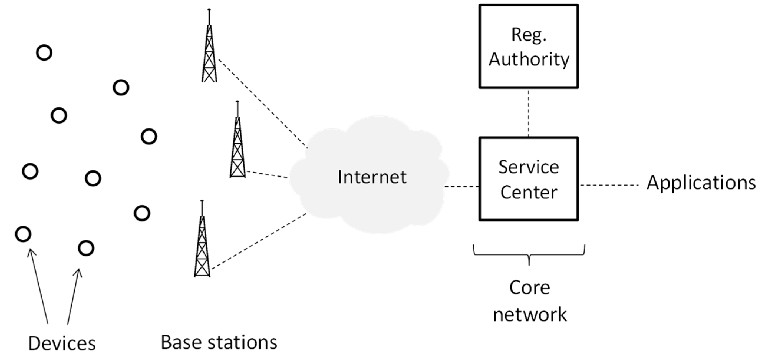
3.1. Network Architecture
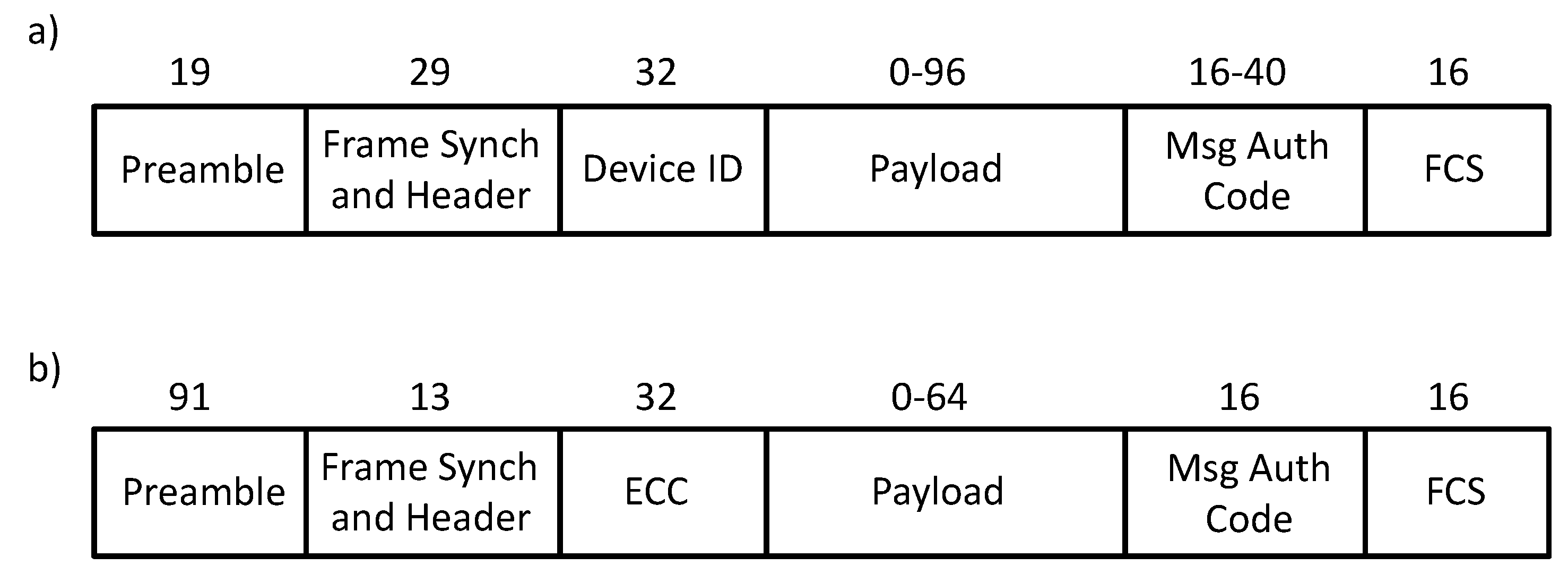
3.2. Sigfox Radio Interface
4. Modeling Sigfox Device Current Consumption
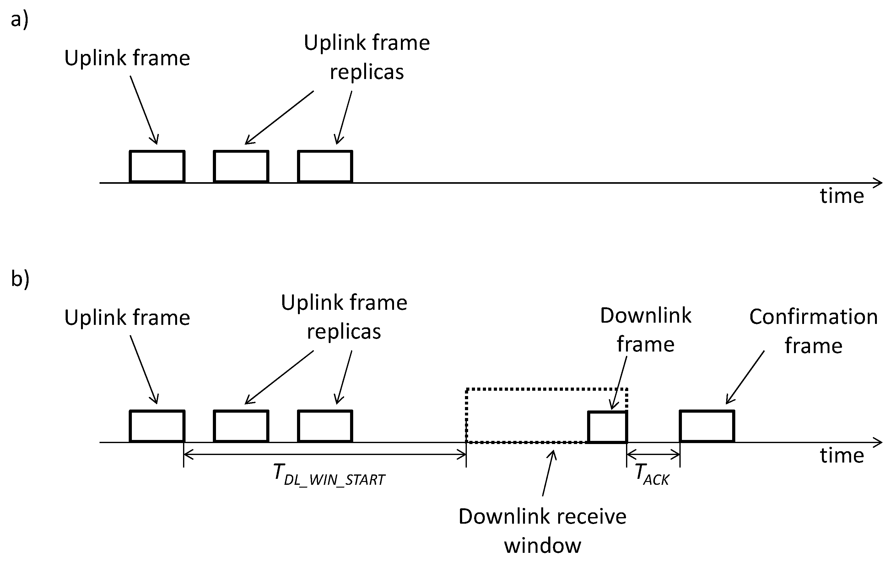
4.1. Unidirectional Transactions
4.2. Bidirectional Transactions
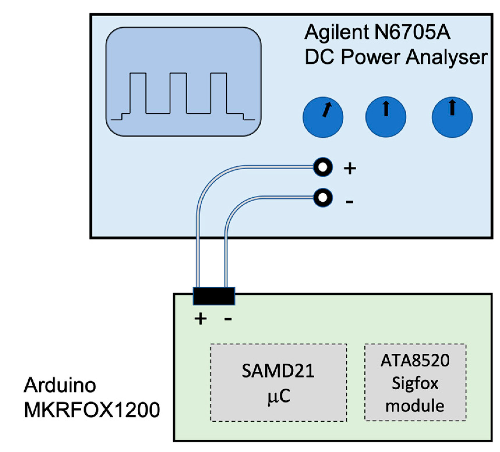
5. Evaluation
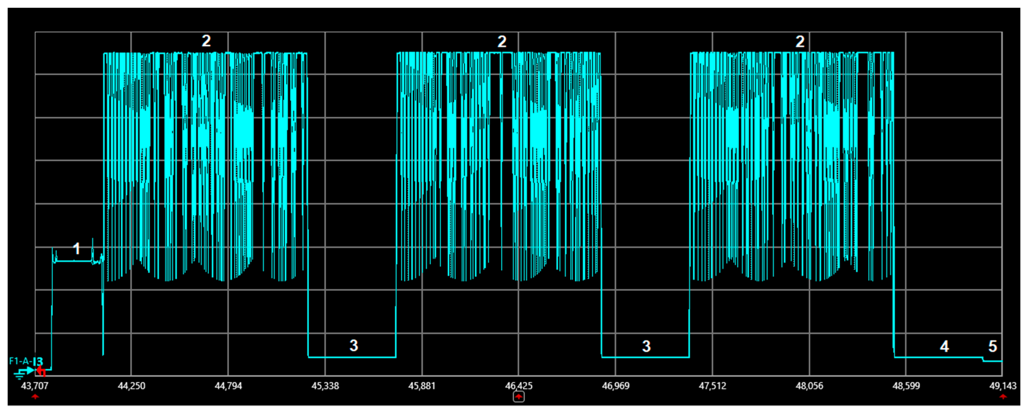
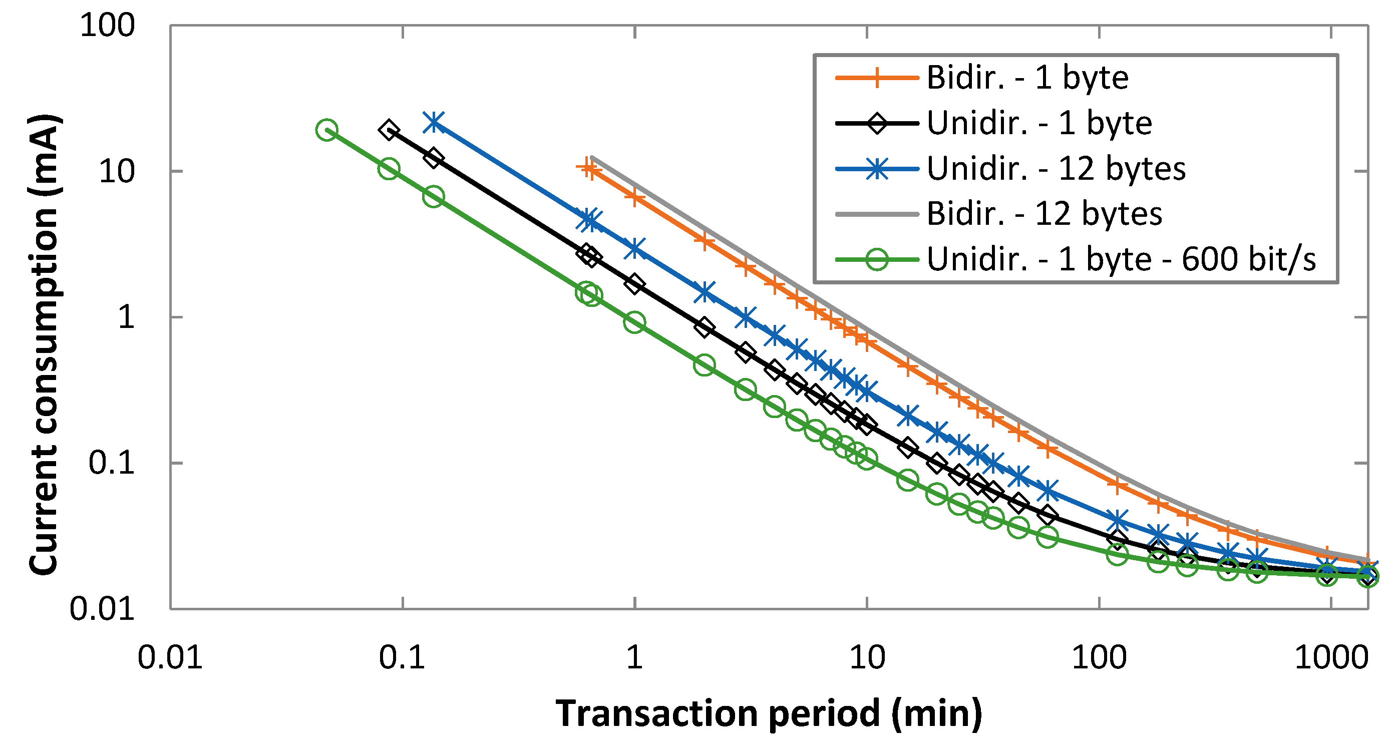
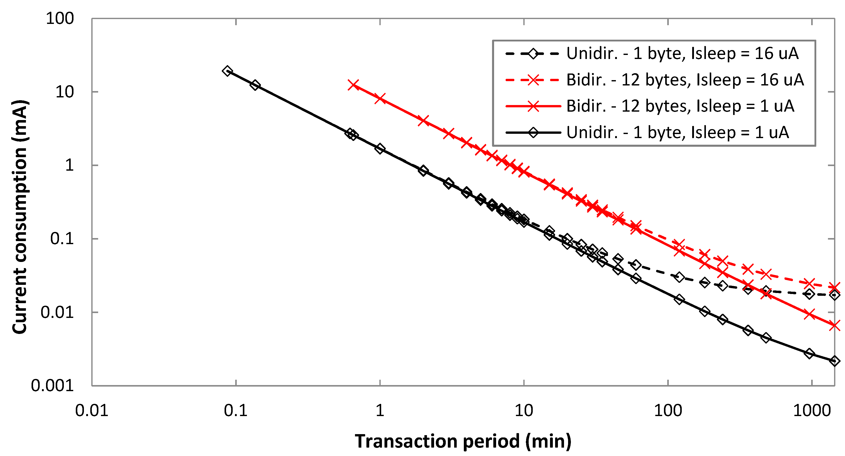
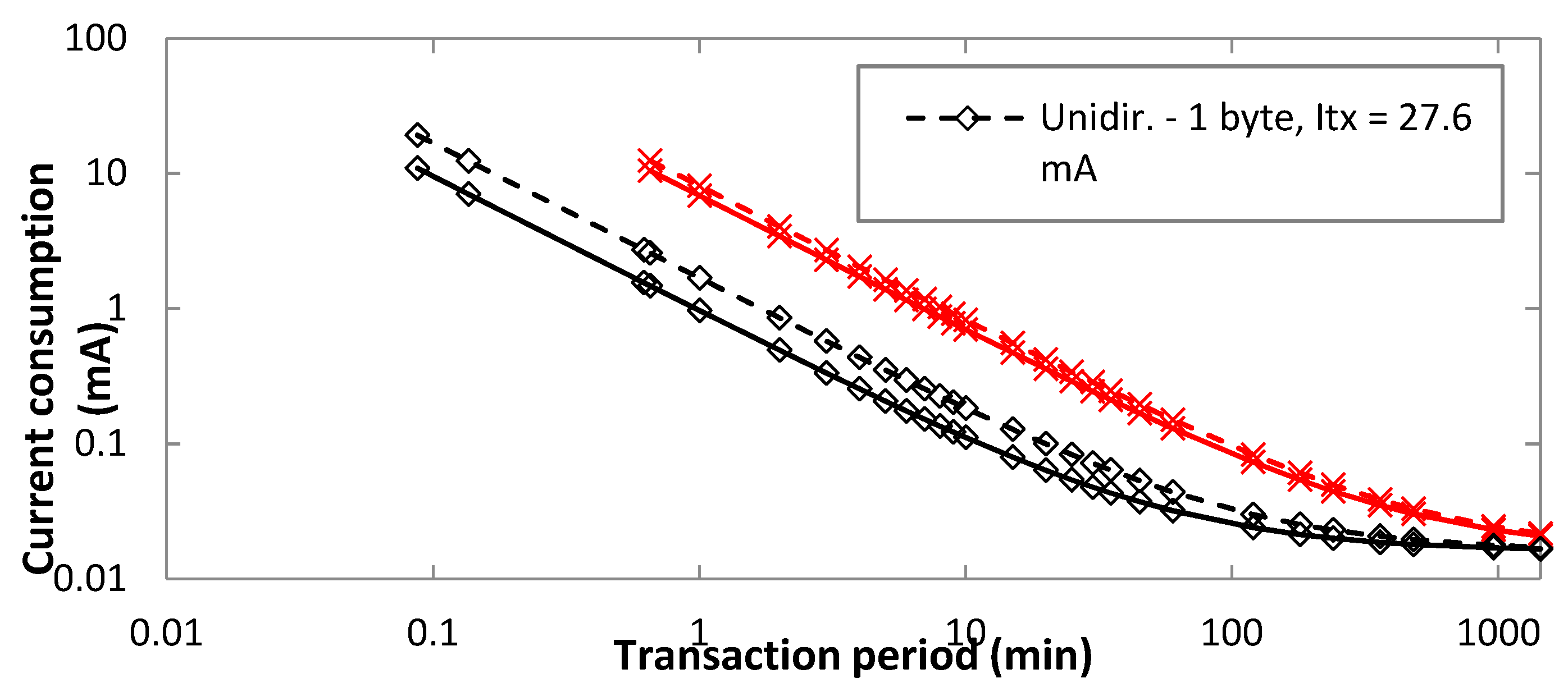
5.1. Device Current Consumption
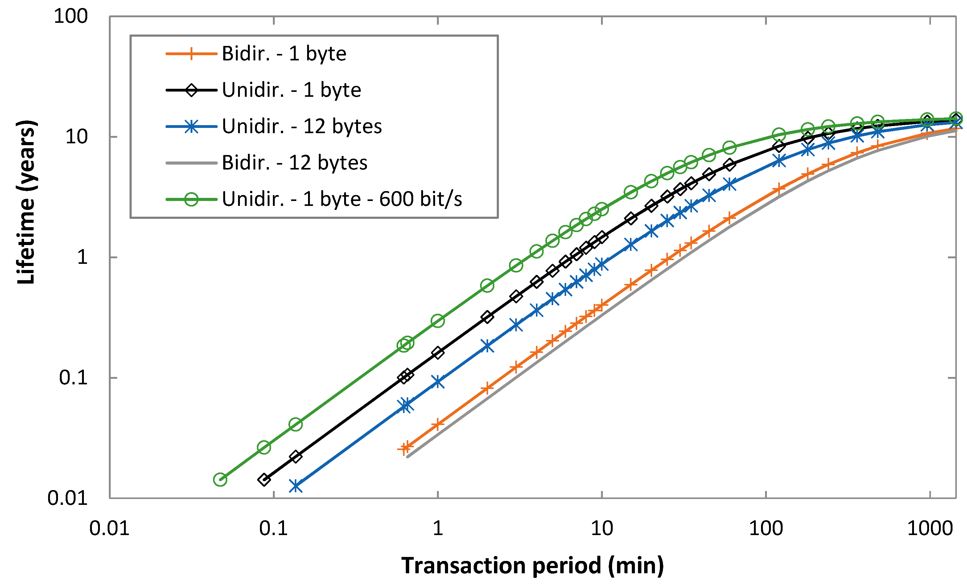
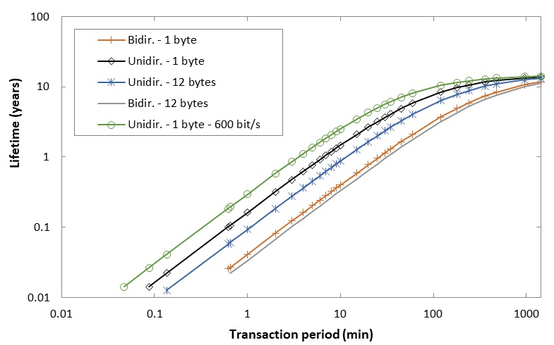
5.2. Device Lifetime
5.3. Energy Cost of Data Delivery
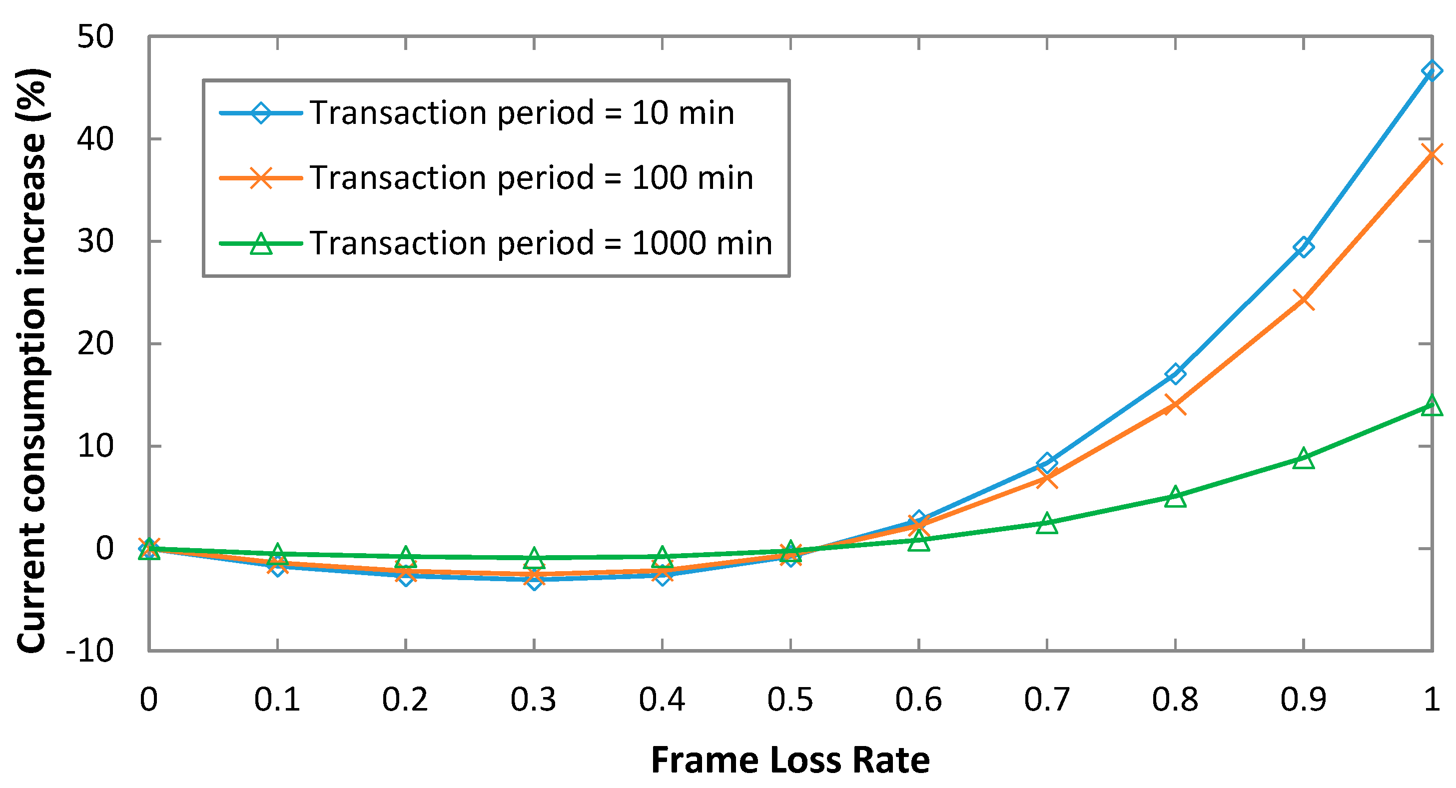
5.4. Impact of Critical Parameters on the Model
5.5. Use of Energy Harvesting
6. Conclusions
Author Contributions
Funding
Acknowledgments
Conflicts of Interest
References
- Raza, U.; Kulkarni, P.; Sooriyabandara, M. Low Power Wide Area Networks: An Overview. IEEE Commun. Surv. Tutor. 2017, 19, 855–873. [Google Scholar] [CrossRef]
- Gomez, C.; Paradells, J.; Bormann, C.; Crowcroft, J. From 6LoWPAN to 6Lo: Expanding the Universe of IPv6-Supported Technologies for the Internet of Things. IEEE Comm. Mag. 2017, 12, 148–155. [Google Scholar] [CrossRef]
- Farrell, S. Low-Power Wide Area Network (LPWAN): Overview. Available online: https://tools.ietf.org/html/rfc8376 (accessed on 7 February 2019).
- Minaburo, A.; Toutain, L.; Gomez, C.; Barthel, D.; Zúñiga, J.C. LPWAN Static Context Header Compression (SCHC) and fragmentation for IPv6 and UDP. IETF Internet Draft 2018. submitted for publication. [Google Scholar]
- Zúñiga, J.C.; Gomez, C.; Toutain, L. SCHC over Sigfox LPWAN. IETF Internet Draft 2018. submitted for publication. [Google Scholar]
- Lauridsen, M.; Vejlgaard, B.; Kovács, I.Z.; Nguyen, H.; Mogensen, P. Interference Measurements in the European 868 MHz ISM Band with Focus on LoRa and SigFox. In Proceedings of the 2017 IEEE Wireless Communications and Networking Conference (WCNC), San Francisco, CA, USA, 19–22 March 2017. [Google Scholar]
- Vejlgaard, B.; Lauridsen, M.; Nguyen, H.C.; Kovács, I.; Mogensen, P.E.; Sørensen, M. Coverage and Capacity Analysis of Sigfox, LoRa, GPRS, and NB-IoT. In Proceedings of the IEEE 85th Vehicular Technology Conference (VTC Spring), Sydney, Australia, 4–7 June 2017. [Google Scholar]
- Lauridsen, M.; Nguyen, H.; Vejlgaard, B.; Kovács, I.; Mogensen, P.E.; Sørensen, M. Coverage comparison of GPRS, NB-IoT, LoRa, and SigFox in a 7800 km2 area. In Proceedings of the IEEE 85th Vehicular Technology Conference (VTC Spring), Sydney, Australia, 4–7 June 2017. [Google Scholar]
- Morin, E.; Maman, M.; Guizzetti, R.; Duda, A. Comparison of the device lifetime in wireless networks for the internet of things. IEEE Access 2017, 5, 7097–7114. [Google Scholar] [CrossRef]
- Finnegan, J.; Brown, S. An Analysis of the Energy Consumption of LPWA-based IoT Devices. In Proceedings of the 2018 IEEE International Symposium on Networks, Computers and Communications (ISNCC), Rome, Italy, Italy 19–21 June 2018. [Google Scholar]
- Hernández, D.M.; Peralta, G.; Manero, L.; Gomez, R.; Bilbao, J.; Zubia, C. Energy and coverage study of LPWAN schemes for Industry 4.0. In Proceedings of the 2017 IEEE International Workshop of Electronics, Control, Measurement, Signals and their Application to Mechatronics (ECMSM), San Sebastian, Spain, 24–26 May 2017. [Google Scholar]
- Ogawa, T.; Yoshimura, T.; Miyaho, N. Cloud Control DTN Utilizing General User’ Smartphones for Narrowband Edge Computing. In Proceedings of the 2018 IEEE 4th World Forum on Internet of Things (WF-IoT), Singapore, 5–8 February 2018. [Google Scholar]
- Ruckebusch, P.; Giannoulis, S.; Moerman, I.; Hoebeke, J.; De Poorter, E. Modelling the energy consumption for over-the-air software updates in LPWAN networks: SigFox, LoRa and IEEE 802.15.4g. Internet Things J. 2018, 3, 104–119. [Google Scholar] [CrossRef]
- Zhou, X.; Flora, E. Comparison of Performance and Power Consumption Between GPS and Sigfox Positioning Using Pycom Modules. Bachelor’s Thesis, Kristianstad University, Kristianstad, Sweden, 30 May 2018. [Google Scholar]
- Martínez, B.; Monton, M.; Vilajosana, I.; Prades, J.D. The power of models: Modeling power consumption for IoT devices. IEEE Sens. J. 2015, 10, 5777–5789. [Google Scholar] [CrossRef]
- ONSEMI AX-Sigfox. Available online: https://www.onsemi.com/pub/Collateral/AX-SIGFOX-D.PDF (accessed on 13 January 2019).
- TD1207R/08R. Available online: https://s3-eu-west-1.amazonaws.com/assetstdnext/download/TD120xR+Datasheet+rev1.2.pdf (accessed on 13 January 2019).
- ONSEMI AXSF. Available online: https://www.onsemi.com/pub/Collateral/AX-SFEU-D.PDF (accessed on 13 January 2019).
- Sigfox Technical Overview. July 2017. Available online: https://www.element14.com/community/servlet/JiveServlet/downloadBody/87914-102-2-369330/Sigfox%20technical%20overview%20July%202017.pdf (accessed on 13 January 2019).
- Arduino MKRFOX1200. Available online: https://www.arduino.cc/en/Main.ArduinoBoardMKRFox1200 (accessed on 13 January 2019).
- Casals, L.; Mir, B.; Vidal, R.; Gomez, C. Modeling the energy performance of LoRaWAN. Sensors 2017, 17, 2364. [Google Scholar] [CrossRef] [PubMed]
- Lesur, L. Battery compatibility with Sigfox technology. Application note. October 2017. Available online: https://support.sigfox.com/docs/battery-application (accessed on 31 January 2019).
- Panasonic AM-1815CA outdoor film solar panel datasheet. Available online: https://www.mouser.es/datasheet/2/315/panasonic_AT-7665A-1196961.pdf (accessed on 31 January 2019).
- Panasonic AM-1815CA indoor glass solar panel datasheet. Available online: https://www.mouser.es/datasheet/2/315/panasonic_AM-1815CA-1197046.pdf (accessed on 31 January 2019).


| Reference | Device Name | Current Consumption: Uplink (left) and Downlink (right) | Source of Values | |||
|---|---|---|---|---|---|---|
| State Name | Value (mA) | State Name | Value (mA) | |||
| [9] | Not specified | Transmission | 49 | Reception | 13 | Not specified |
| Sleep | 1.44 × 10⁻³ | |||||
| [10] | ONSEMI AX-Sigfox | Tx (0 dBm) | 19 | - | - | Datasheet [16] |
| Tx (14 dBm) | 49 | |||||
| Standby | 0.5 | |||||
| Sleep | 1.3 × 10⁻³ | |||||
| [11] | Telit LE51-868/DIP | Cmd | 8.4 | Cmd | 8.4 | Empirical |
| Tx | 54 | Tx | 54 | |||
| Delay Tx | 12 | Delay Tx | 12 | |||
| Standby | <0.1 (a) | Standby | <0.1 | |||
| RxW | 34 | |||||
| Delay Rx | 8.4 | |||||
| Rx | 34 | |||||
| [12] | TD1207R/08R | Transmission | 50 | Reception | 13 | Datasheet [17] |
| [13] | ONSEMI AXSFEU | Transmission | 49 | Reception | 10 | Datasheet [18] |
| [14] | FiPy | Wake up 1 | 80 | - | - | Empirical |
| Wake up 2 | 160 | |||||
| Idle | 280 | |||||
| Tx | 0.32/0.42 | |||||
| Deep sleep | 25 × 10−3 | |||||
| State Number | Description | Duration | Current Consumption | ||
|---|---|---|---|---|---|
| Variable | Value (ms) | Variable | Value (mA) | ||
| 1 | Wake up | Twu | 287 | Iwu | 10.4 |
| 2 | Transmission | Ttx | [1200,2080] (4) | Itx | 27.2 |
| 3 | Wait next transmission | Twntx | 486 | Iwntx | 1.2 |
| 4 | Cool down | Tcd | 510 | Icd | 1.2 |
| 5 | Sleep | Tsleep_uni | [0,TPeriod) (2) | Isleep | 16 × 10−3 |
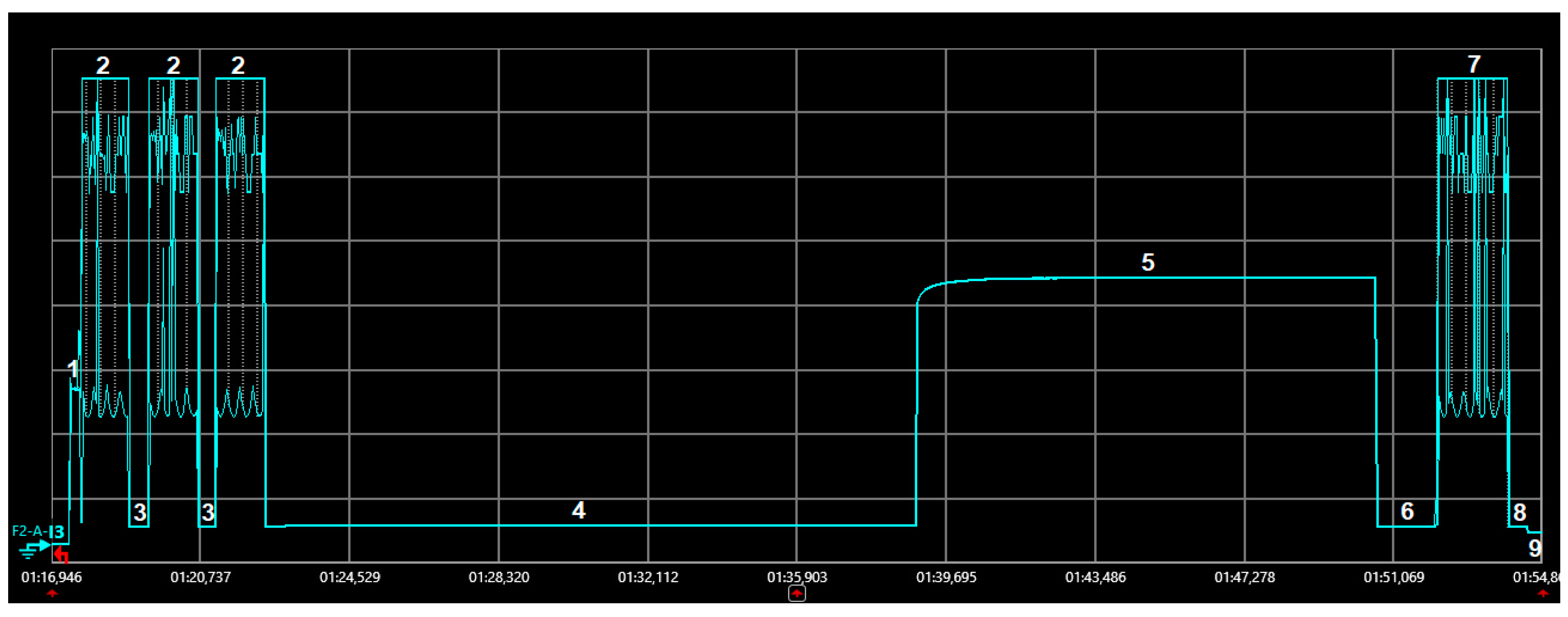
| State Number | Description | Duration | Current Consumption | ||
|---|---|---|---|---|---|
| Variable | Value (ms) | Variable | Value (mA) | ||
| 1 | Wake up | Twu | 305 | Iwu | 10.7 |
| 2 | Transmission | Ttx | [1200,2080] (4) | Itx | 27.6 |
| 3 | Wait next transmission | Twntx | 493 | Iwntx | 1.2 |
| 4 | Wait next reception | Twnrx | 16493 | Iwnrx | 1.3 |
| 5 | Reception | Trx | 12690 (11) | Irx | 18.5 |
| 6 | Wait confirm. transmission | Twctrl | 1430 | Iwctrl | 1.2 |
| 7 | Confirmation transmission | Tctrl_tx | 1850 | Ictrl_tx | 27.0 |
| 8 | Cool down | Tcd | 495 | Icd | 1.2 |
| 9 | Sleep | Tsleep_bi | [0,TPeriod) (9) | Isleep | 16 × 10−3 |
| Transaction | Energy Required (mJ) | Outdoor Panel: Minimum TPeriod (min) | Indoor Panel: Minimum TPeriod (min) |
|---|---|---|---|
| 1-byte, unidirectional | 2.61 | 0.09 | 54.1 |
| 12-byte, unidirectional | 4.56 | 0.14 | 94.7 |
| 1-byte, bidirectional | 10.3 | 0.62 | 214.6 |
| 12-byte, bidirectional | 12.6 | 0.65 | 261.2 |
© 2019 by the authors. Licensee MDPI, Basel, Switzerland. This article is an open access article distributed under the terms and conditions of the Creative Commons Attribution (CC BY) license (http://creativecommons.org/licenses/by/4.0/).
Share and Cite
Gomez, C.; Veras, J.C.; Vidal, R.; Casals, L.; Paradells, J. A Sigfox Energy Consumption Model. Sensors 2019, 19, 681. https://doi.org/10.3390/s19030681
Gomez C, Veras JC, Vidal R, Casals L, Paradells J. A Sigfox Energy Consumption Model. Sensors. 2019; 19(3):681. https://doi.org/10.3390/s19030681
Chicago/Turabian StyleGomez, Carles, Juan Carlos Veras, Rafael Vidal, Lluís Casals, and Josep Paradells. 2019. "A Sigfox Energy Consumption Model" Sensors 19, no. 3: 681. https://doi.org/10.3390/s19030681
APA StyleGomez, C., Veras, J. C., Vidal, R., Casals, L., & Paradells, J. (2019). A Sigfox Energy Consumption Model. Sensors, 19(3), 681. https://doi.org/10.3390/s19030681